

Page 1
USER INSTRUCTIONS
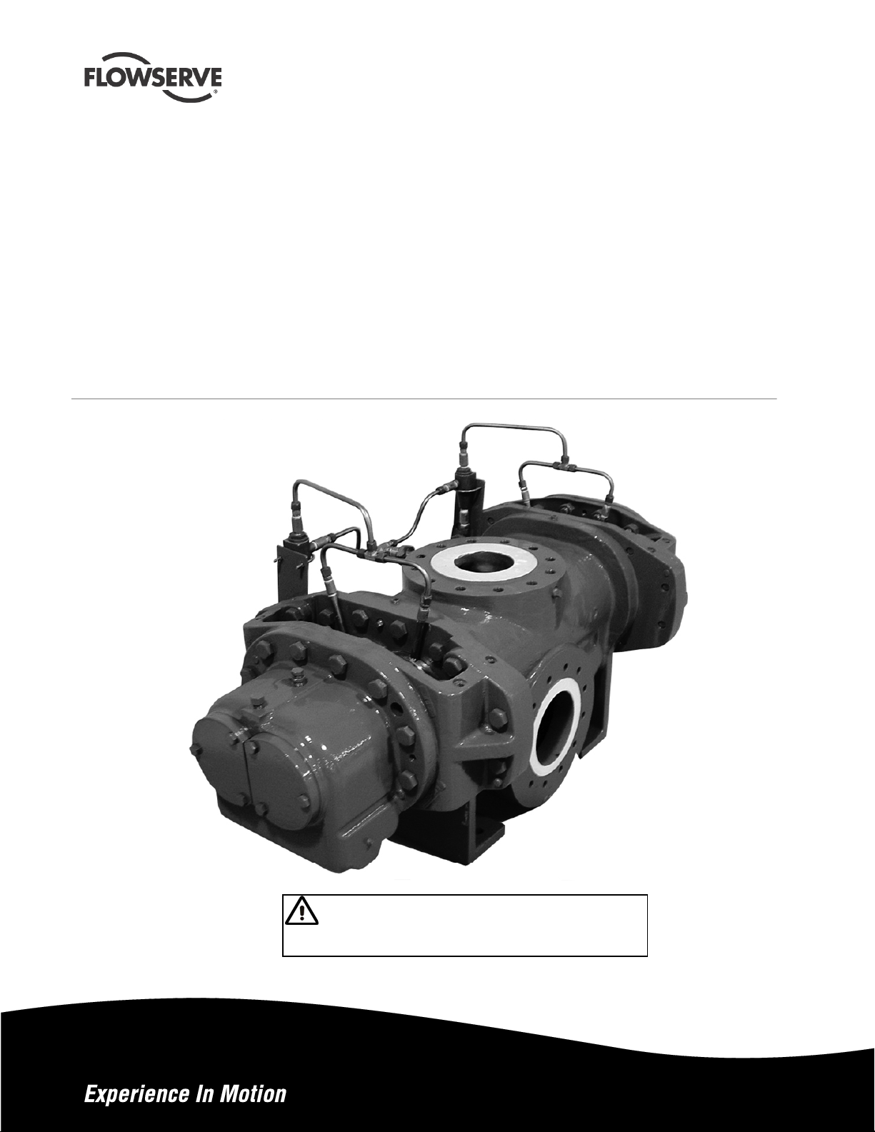
Twin Screw Rotary Pumps
External and Internal Bearing Design
PCN=71569243/71569244 – 07/10 (E)
Original Instructions
Installation
Operation
Maintenance
These instructions must be read prior to installing,
operating, using, and maintaining this equipment.
Page 2

TWIN SCREW PUMPS. ORIGINAL USER INSTRUCTIONS. ENGLISH. 71569243 – 07/10
®
CONTENTS
PAGE
1 INTRODUCTION AND SAFETY ...........................1
1.1 General ...........................................................1
1.2 CE marking and approvals..............................1
1.3 Disclaimer .......................................................1
1.4 Copyright.........................................................1
1.5 Duty conditions................................................1
1.6 Safety ..............................................................2
1.7 Nameplate and warning labels........................6
1.8 Specific machine performance........................7
1.9 Noise level.......................................................7
2 TRANSPORT AND STORAGE.............................8
2.1 Consignment receipt and unpacking...............8
2.2 Handling.......................................................... 8
2.3 Lifting...............................................................8
2.4 Storage............................................................8
2.5 Recycling and end of product life.................... 9
3 PUMP DESCRIPTION........................................... 9
3.1 Configurations.................................................9
3.2 Name structure................................................9
NJHP...................9
3.3 Design of major parts......................................9
3.4 Performance and operating limits.................10
3.5 Table of Engineering Data.............................11
6.4 Tools required ............................................... 36
6.5 Torques for fasteners.................................... 36
6.6 Renewal clearances ..................................... 37
6.7 Disassembly.................................................. 37
6.8 Examination of parts..................................... 38
6.9 Assembly ...................................................... 38
6.10 New Rotating Elements.............................. 40
6.11 Free Movement........................................... 41
6.12 Timing Gear Replacement.......................... 41
7 FAULTS; CAUSES AND REMEDIES.................. 44
8 PARTS LIST AND DRA WI NGS........................... 46
8.1 Sectional Drawings-Typical............................46
8.2 General Arrangement Drawing..................... 51
9 CERTIFICATION................................................. 52
10 OTHER RELEVANT DOCUMENTATION AND
MANUALS ....................................................... 52
10.1 Supplementary User Instruction manuals... 52
10.2 Change notes ............................................. 52
10.3 Additional sources of information................ 52
11.0 OPTIONAL EQUIPMENT AND
ARRANGEMENTS .......................................... 52
11.1 Jacketed components................................. 52
11.2 Vertical mountings...................................... 52
4 INSTALLATION....................................................20
4.1 Location.........................................................20
4.2 Part assemblies.............................................20
4.3 Foundation....................................................20
4.4 Baseplate installation....................................20
4.5 Initial alignment.............................................21
4.6 Grouting ........................................................23
4.7 Piping............................................................23
4.8 Pressure gauges...........................................25
4.9 Final shaft alignment check ..........................25
4.10 Electrical connections ................................. 25
4.11 Protection systems......................................25
5 COMMISSIONING, START-UP, OPERA TION AND
SHUTDOWN....................................................26
5.1 Pre-commissioning procedure......................26
5.2 Lubricants.....................................................26
5.3 Direction of rotation.......................................28
5.4 Guarding .......................................................28
5.5 Priming and auxiliary supplies ......................28
5.6 Starting the pump..........................................28
5.7 High Temperature Startup..............................29
5.8 Post start-up..................................................29
5.9 Running the pump.........................................29
5.10 Stopping and shutdown...............................30
5.11 Hydraulic, mechanical and electrical duty...31
6 MAINTENANCE...................................................33
6.1 General .........................................................33
6.2 Maintenance schedule..................................33
6.3 Spare parts....................................................34
ii
Page 3

TWIN SCREW PUMPS. ORIGINAL USER INSTRUCTIONS. ENGLISH. 71569243 – 07/10
®
INDEX
PAGE
Alignment of shafting (see 4.5 and 4.9) .............21,25
CE marking and approvals (1.2)................................1
Clearances (see 6.6, Renewal clearances).............38
Commissioning and operation (see 5).....................27
Configurations (3.1)...................................................9
Direction of rotation (5.3).........................................29
Dismantling (see 6.7, Disassembly)........................38
Duty conditions (1.5)..................................................1
Electrical connections (4.10) ...................................25
Examination of parts (6.8)........................................39
Grouting (4.6)...........................................................23
Guarding (5.4)..........................................................29
Handling (2.2)............................................................8
Hydraulic, mechanical and electrical duty (5.11).....32
Lifting (2.3).................................................................8
Location (4.1)...........................................................20
Lubrication schedule (see 5.2, Pump lubricants) ....27
Maintenance schedule (6.2)....................................34
Piping (4.7) ..............................................................24
Priming and auxiliary supplies (5.5).........................29
Reassembly (see 6.9, Assembly)............................39
Replacement parts (see 6.3 and 6.4).................35,37
Safety, protection systems (see 1.6 and 4.11) ....2,26
Sound level (see 1.9, Noise level)............................. 7
Specific machine performance (1.8)..........................7
Starting the pump (5.6)............................................29
Stopping and shutdown (5.10).................................31
Storage (2.4)..............................................................8
Tools required (6.4) .................................................37
Torques for fasteners (6.5)......................................37
iii
Page 4

TWIN SCREW PUMPS. ORIGINAL USER INSTRUCTIONS. ENGLISH. 71569243 – 07/10
®
1 INTRODUCTION AND SAFETY
1.1 General
These instructions must always be kept
close to the product's operating location or
directly with the product.
Flowserve's products are designed, developed and
manufactured with state-of-the-art technologies in
modern facilities. The unit is produced with great care
and commitment to continuous quality control, utilising
sophisticated quality techniques, and safety
requirements.
We are committed to continuous quality improvement
and being at your service for any further information
about the product in its installation and operation or
about its support products, repair and diagnostic
services.
These instructions are intended to facilitate
familiarization with the product and its permitted use.
Operating the product in compliance with these
instructions is important to help ensure reliability in
service and avoid risks. The instructions may not take
into account local regulations; ensure such regulations
are observed by all, including those installing the
product. Always coordinate repair activity with
operations personnel, and follow all plant safety
requirements and applicable safety and health laws
and regulations.
These instructions should be read prior to
installing, operating, using and maintaining the
equipment in any region worldwide. The
equipment must not be put into service until all
the conditions relating to safety noted in the
instructions, have been met.
1.2 CE marking and approvals
It is a legal requirement that machinery and
equipment put into service within certain regions of
the world shall conform with the applicable CE
Marking Directives covering Machinery and, where
applicable, Low Voltage Equipment, Electromagnetic
Compatibility (EMC), Pressure Equipment Directive
(PED) and Equipment for Potentially Explosive
Atmospheres (ATEX).
Where applicable, the Directives and any additional
Approvals, cover important safety aspects relating to
machinery and equipment and the satisfactory
provision of technical documents and safety
instructions. Where applicable this document
incorporates information relevant to these Directives.
To establish approvals and if the product itself is CE
marked, check the serial number plate and the
Certification (See section 9 Certification).
1.3 Disclaimer
Information in these User Instructions is believed
to be reliable. In spite of all the efforts of
Flowserve Corporation to provide sound and all
necessary information the content of this manual
may appear insufficient and is not guaranteed by
Flowserve as to its completeness or accuracy.
Flowserve manufactures products to exacting
International Quality Management System Standards
as certified and audited by external Quality Assurance
organisations. Genuine parts and accessories have
been designed, tested and incorporated into the
products to help ensure their continued product quality
and performance in use. As Flowserve cannot test
parts and accessories sourced from other vendors the
incorrect incorporation of such parts and accessories
may adversely affect the performance and safety
features of the products. The failure to properly
select, install or use authorised Flowserve parts and
accessories is considered to be misuse. Damage or
failure caused by misuse is not covered by
Flowserve's warranty. In addition, any modification of
Flowserve products or removal of original components
may impair the safety of these products in their use.
1.4 Copyright
All rights reserved. No part of these instructions may
be reproduced, stored in a retrieval system or
transmitted in any form or by any means without prior
permission of Flowserve Pump Division.
1.5 Duty conditions
This product has been selected to meet the
specifications of your purchaser order. The
acknowledgement of these conditions has been sent
separately to the Purchaser. A copy should be kept
with these instructions.
The product must not be operated beyond
the parameters specified for the application. If
there is any doubt as to the suitability of the
product for the application intended, contact
Flowserve for advice, quoting the serial number.
If the conditions of service on your purchase order are
going to be changed (for example liquid pumped,
temperature or duty) it is requested that you/the user
seek our written agreement before start up.
Page 1 of 53
Page 5
TWIN SCREW PUMPS. ORIGINAL USER INSTRUCTIONS. ENGLISH. 71569243 – 07/10
®
1.6 Safety
1.6.1 Summary of safety markings
These user instructions contain specific safety
markings where non-observance of an instruction
would cause hazards. The specific safety markings
are:
This symbol indicates electrical safety
instructions where non-compliance would affect
personal safety.
This symbol indicates safety instructions where
non-compliance would affect personal safety.
This symbol indicates safety instructions where
non-compliance would affect protection of a safe life
environment.
This symbol indicates safety instructions
where non-compliance would affect the safe operation
or protection of the pump or pump unit.
This symbol indicates explosive atmosphere
zone marking according to ATEX. It is used in safety
instructions where non-compliance in the hazardous
area would cause the risk of an explosion.
This sign is not a safety symbol but
indicates an important instruction in the assembly
process.
1.6.2 Personnel qualification and training
All personnel involved in the operation, installation,
inspection and maintenance of the unit must be
qualified to carry out the work involved. If the
personnel in question do not already possess the
necessary knowledge and skill, appropriate training
and instruction must be provided. If required the
operator may commission the manufacturer/supplier
to provide applicable training.
Always coordinate repair activity with operations and
health and safety personnel, and follow all plant safety
requirements and applicable safety and health laws
and regulations.
1.6.3 Safety action
This is a summary of conditions and actions to
prevent injury to personnel and damage to the
environment and to equipment. (For products
used in potentially explosive atmospheres section
1.6.4 also applies.)
PREVENT EXCESSIVE EXTERNAL
PIPE LOAD
Do not use pump as a support for piping. Do not
mount expansion joints, unless allowed by Flowserve
in writing, so that their force, due to internal pressure,
acts on the pump flange.
ENSURE CORRECT LUBRICATION
(See section 5 COMMISSIONING, START-UP,
OPERA TION AND SHUTDOWN.)
START THE PUMP WITH OUTLET
VALVE PART OPENED
(Unless otherwise instructed at a specific point in the
user instructions.)
This is recommended to minimize the risk of
overloading and damaging the pump motor at full or
zero flow. Pumps may be started with the valve
further open only on installations where this situation
cannot occur. The pump outlet control valve may
need to be adjusted to comply with the duty following
the run-up process. (See section 5 COMMISSIONING,
START-UP, OPERATION AND SHUTDOWN.)
NEVER RUN THE PUMP DRY
INLET VALVES TO BE FULLY OPEN
WHEN PUMP IS RUNNING
Running the pump at zero flow or below the
recommended minimum flow continuously will cause
damage to the seal.
DO NOT RUN THE PUMP AT
ABNORMALLY HIGH OR LOW FLOW RATES
Operating at a flow rate higher than normal or at a
flow rate with no back pressure on the pump may
overload the motor and cause cavitation. Low flow
rates may cause a reduction in pump/bearing life,
overheating of the pump, instability and cavitation/
vibration.
NEVER DO MAINTENANCE WORK
WHEN THE UNIT IS CONNECTED TO POWER
HAZARDOUS LIQUIDS
When the pump is handling hazardous liquids care
must be taken to avoid exposure to the liquid by
appropriate siting of the pump, limiting personnel
access and by operator training. If the liquid is
flammable and/or explosive, strict safety procedures
must be applied.
Gland packing must not be used when pumping
hazardous liquids.
Page 2 of 53
Page 6
TWIN SCREW PUMPS. ORIGINAL USER INSTRUCTIONS. ENGLISH. 71569243 – 07/10
®
RELIEF VALVE PIPED BACK TO THE
SUCTION LINE REQUIRED
The Twin Screw Pumps are positive displacement
pumps and will build up considerable pressure if
discharge line is blocked.
DRAIN THE PUMP AND ISOLATE PIPEWORK
BEFORE DISMANTLING THE PUMP
The appropriate safety precautions should be taken
where the pumped liquids are hazardous.
FLUORO-ELASTOMERS (When fitted.)
When a pump has experienced temperatures over
250 ºC (482 ºF), partial decomposition of fluoroelastomers (eg Viton) will occur. In this condition
these are extremely dangerous and skin contact must
be avoided.
HANDLING COMPONENTS
Many precision parts have sharp corners and the
wearing of appropriate safety gloves and equipment is
required when handling these components. To lift
heavy pieces above 25 kg (55 lb) use a crane
appropriate for the mass and in accordance with
current local regulations.
GUARDS MUST NOT BE REMOVED WHILE
THE PUMP IS OPERATIONAL
THERMAL SHOCK
Rapid changes in the temperature of the liquid within
the pump can cause thermal shock, which can result
in damage or breakage of components and should be
avoided.
NEVER APPLY HEAT TO REMOVE ROTOR
Trapped lubricant or vapour could cause an explosion.
HOT (and cold) PARTS
If hot or freezing components or auxiliary heating
supplies can present a danger to operators and
persons entering the immediate area action must be
taken to avoid accidental contact. If complete
protection is not possible, the machine access must
be limited to maintenance staff only, with clear visual
warnings and indicators to those entering the
immediate area. Note: bearing housings must not be
insulated and drive motors and bearings may be hot.
If the temperature is greater than 68 °C (175 °F) or
below 5 °C (20 °F) in a restricted zone, or exceeds
local regulations, action as above shall be taken.
1.6.4 Products used in potentially explosive
atmospheres
Measures are required to:
• Avoid excess temperature
• Prevent build up of explosive mixtures
• Prevent the generation of sparks
• Prevent leakages
• Maintain the pump to avoid hazard
The following instructions for pumps and pump units
when installed in potentially explosive atmospheres
must be followed to help ensure explosion protection.
Both electrical and non-electrical equipment must
meet the requirements of European Directive 94/9/EC.
1.6.4.1 Scope of compliance
Use equipment only in the zone for which it is
appropriate. Always check that the driver, drive
coupling assembly, seal and pump equipment are
suitably rated and/or certified for the classification of the
specific atmosphere in which they are to be installed.
Where Flowserve has supplied only the bare shaft
pump, the Ex rating applies only to the pump. The
party responsible for assembling the pump set shall
select the coupling, driver and any additional
equipment, with the necessary CE Certificate/
Declaration of Conformity establishing it is suitable for
the area in which it is to be installed.
The output from a variable frequency drive (VFD) can
cause additional heating effects in the motor and so,
for pumps sets with a VFD, the ATEX Certification for
the motor must state that it is covers the situation
where electrical supply is from the VFD. This
particular requirement still applies even if the VFD is
in a safe area.
Page 3 of 53
Page 7
TWIN SCREW PUMPS. ORIGINAL USER INSTRUCTIONS. ENGLISH. 71569243 – 07/10
®
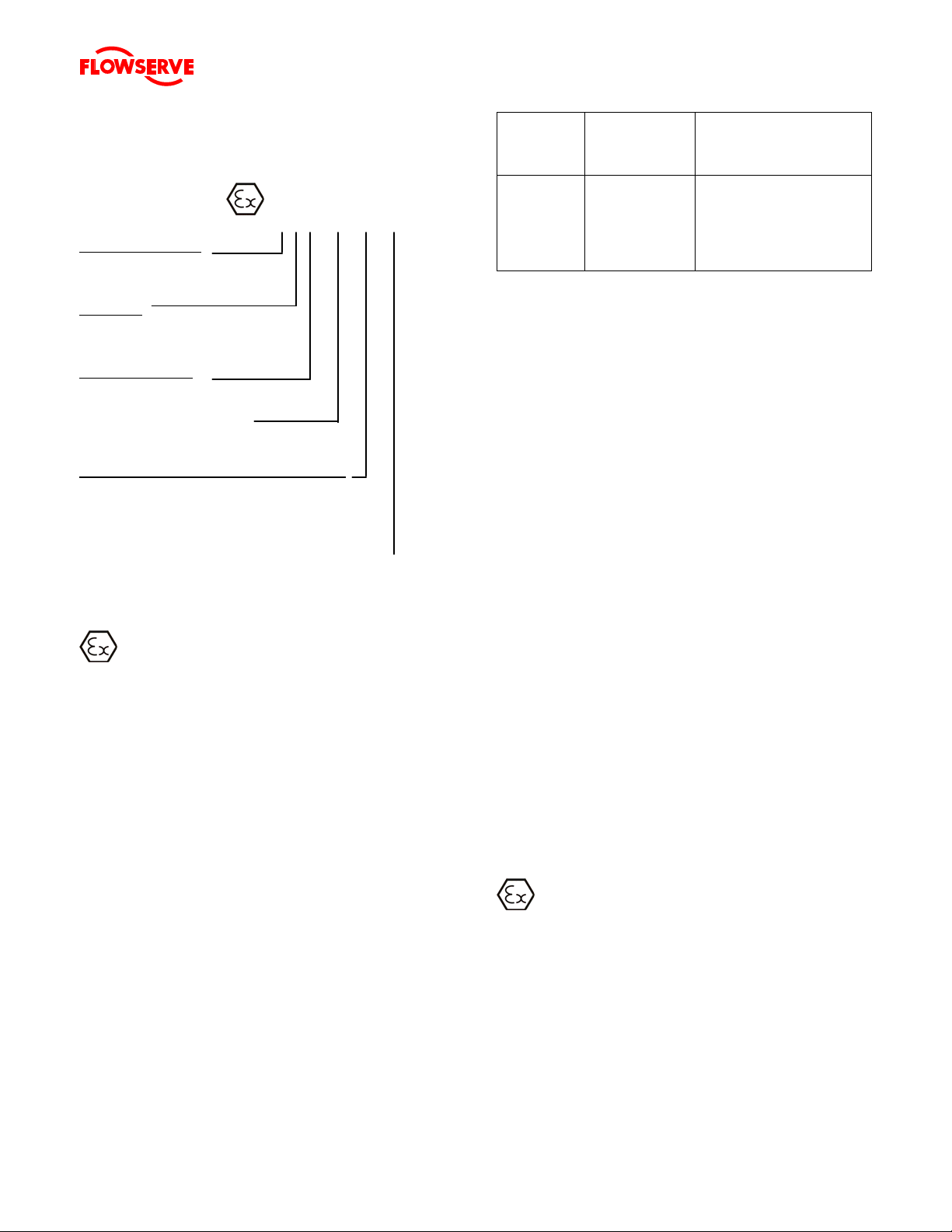
1.6.4.2 Marking
An example of ATEX equipment marking is shown
below. The actual classification of the pump will be
engraved on the nameplate.
II 2 GD c IIC 135 ºC (T4)
Equipment Group
I = Mining
II = Non-mining
Category
2 or M2 = High level protection
3 = normal level of protection
Gas and/or Dust
G = Gas; D= Dust
c = Constructional safety
(in accordance with EN13463-5)
Gas Group (Equipment Category 2 only)
IIA – Propane (typical)
IIB – Ethylene (typical)
IIC – Hydrogen (typical)
Maximum surface temperature (Temperature Class)
(See section 1.6.4.3.)
1.6.4.3 Avoiding excessive surface temperatures
ENSURE THE EQUIPMENT TEMPERATURE
CLASS IS SUITABLE FOR THE HAZARD ZONE
Pumps have a temperature class as stated in the
ATEX Ex rating on the nameplate. These are based
on a maximum ambient of 40 °C (104 °F); refer to
Flowserve for higher ambient temperatures.
The surface temperature on the pump is influenced by
the temperature of the liquid handled. The maximum
permissible liquid temperature depends on the
temperature class and must not exceed the values in
the table that follows.
The temperature rise at the seals and bearings and
due to the minimum permitted flow rate is taken into
account in the temperatures stated.
Temperature
class to
EN 13463-1
T6
T5
T4
T3
T2
T1
Maximum
surface
temperature
permitted
85 °C (185 °F)
100 °C (212 °F)
135 °C (275 °F)
200 °C (392 °F)
300 °C (572 °F)
450 °C (842 °F)
Temperature limit of liquid
handled (* depending on
material and construction
variant - check which is lower)
Consult Flowserve
Consult Flowserve
115 °C (239 °F) *
180 °C (356 °F) *
275 °C (527 °F) *
400 °C (752 °F) *
The responsibility for compliance with the specified
maximum liquid temperature is with the plant
operator.
Temperature classification “Tx” is used when the liquid
temperature varies and when the pump is required to be
used in differently classified potentially explosive
atmospheres. In this case the user is responsible for
ensuring that the pump surface temperature does not
exceed that permitted in its a ctual inst alled l ocatio n.
If an explosive atmosphere exists during the
installation, do not attempt to check the direction of
rotation by starting the pump unfilled. Even a short
run time may give a high temperature resulting from
contact between rotating and stationary components.
Where there is any risk of the pump being run against a
closed valve generating high liquid and casing external
surface temperatures it is recommended that users fit
an external surface temperature protection device.
Avoid mechanical, hydraulic or electrical overload by
using motor overload trips, temperature monitor or a
power monitor and make routine vibration monitoring
checks.
In dirty or dusty environments, regular checks must be
made and dirt removed from areas around close
clearances, bearing housings and motors.
1.6.4.4 Preventing the build up of explosive
mixtures
ENSURE THE PUMP IS PROPERLY FILLED
AND VENTED AND DOES NOT RUN DRY
Ensure the pump and relevant suction and discharge
pipeline system is totally filled with liquid at all times
during the pump operation, so that an explosive
atmosphere is prevented. In addition it is essential to
make sure that seal chambers, auxiliary shaft seal
systems and any heating and cooling systems are
properly filled.
Page 4 of 53
Page 8

TWIN SCREW PUMPS. ORIGINAL USER INSTRUCTIONS. ENGLISH. 71569243 – 07/10
®
If the operation of the system cannot avoid this
condition the fitting of an appropriate dry run
protection device is recommended (eg liquid detection
or a power monitor).
To avoid potential hazards from fugitive emissions of
vapour or gas to atmosphere the surrounding area
must be well ventilated.
1.6.4.5 Preventing sparks
To prevent a potential hazard from mechanical
contact, the coupling guard must be non-sparking and
anti-static for Category 2.
To avoid the potential hazard from random induced
current generating a spark, the earth contact on the
baseplate must be used.
Avoid electrostatic charge: do not rub non-metallic
surfaces with a dry cloth; ensure cloth is damp.
The coupling must be selected to comply with 94/9/EC
and correct alignment must be maintained.
1.6.4.6 Preventing leakage
The pump must only be used to handle liquids
for which it has been approved to have the correct
corrosion resistance.
Avoid entrapment of liquid in the pump and associated
piping due to closing of suction and discharge valves,
which could cause dangerous excessive pressures to
occur if there is heat input to the liquid. This can occur
if the pump is stationary or running.
Bursting of liquid containing parts due to freezing must
be avoided by draining or protecting the pump and
ancillary systems.
Where there is the potential hazard of a loss of a seal
barrier fluid or external flush, the fluid must be
monitored.
If leakage of liquid to atmosphere can result in a
hazard, the installation of a liquid detection device is
recommended.
1.6.4.7 Maintenance to avoid the hazard
CORRECT MAINTENANCE IS REQUIRED TO
AVOID POTENTIAL HAZARDS WHICH GIVE A RISK
OF EXPLOSION
The responsibility for compliance with
maintenance instructions is with the plant
operator.
To avoid potential explosion hazards during
maintenance, the tools, cleaning and painting
materials used must not give rise to sparking or
adversely affect the ambient conditions. Where there
is a risk from such tools or materials, maintenance
must be conducted in a safe area.
It is recommended that a maintenance plan and
schedule is adopted.(See section 6 MAINTENANCE.)
Page 5 of 53
Page 9
TWIN SCREW PUMPS. ORIGINAL USER INSTRUCTIONS. ENGLISH. 71569243 – 07/10
®
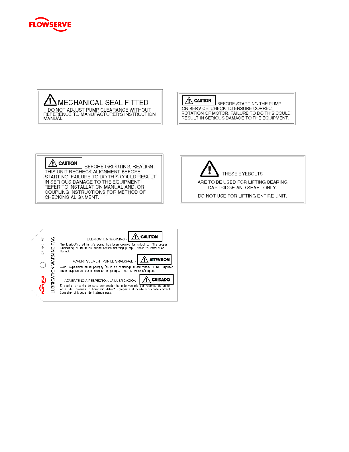
1.7 Nameplate and warning labels
1.7.1 Nameplate
For details of nameplate, see the Declaration of Conformity.
1.7.2 Safety labels
P/N 2113931-001 P/N 2113932-001
MECHANICAL SEAL WARNING ROTATION WARNING
GROUT WARNING LIFTING WARNING
P/N 2113934-001 P/N 9901701-001
LUBRICATION WARNING – QF-440-R01 (2124841)
Oil lubricated units only
Page 6 of 53
Page 10

TWIN SCREW PUMPS. ORIGINAL USER INSTRUCTIONS. ENGLISH. 71569243 – 07/10
®
1.8 Specific machine performance
For performance parameters see section 1.5 Duty
conditions. When the contract requirement specifies
these to be incorporated into User Instructions these
are included here. Where performance data has been
supplied separately to the purchaser these should be
obtained and retained with these User Instructions if
required.
1.9 Noise level
Attention must be given to the exposure of personnel to
the noise, and local legislation will define when
guidance to personnel on noise limitation is required,
and when noise exposure reduction is mandatory. This
is typically 80 to 85 dBA.
The usual approach is to control the exposure time to
the noise or to enclose the machine to reduce emitted
sound. You may have already specified a limiting noise
level when the equipment was ordered, however if no
noise requirements were defined, then attention is
drawn to the following table to give an indication of
equipment noise level so that you can take the
appropriate action in your plant.
Pump noise level is dependent on a number of
operational factors, flow rate, pipework design and
acoustic characteristics of the building, and so the
values given are subject to a 3 dBA tolerance and
cannot be guaranteed.
Similarly the motor noise a ssumed in t he “pump and
motor” noise is that typically expected from standard and
high efficiency motors when on load directly driving t he
pump. Note that a motor driven by an inverter may show
an increased noise at some speeds.
If a pump unit only has been purchased for fitting with
your own driver then the “pump only” noise levels in the
table should be combined with the level for the driver
obtained from the supplier. Consult Flowserv e or a noise
specialist if assistance is required in combining the values.
It is recommended that where exposure approaches
the prescribed limit, then site noise measurements
should be made.
The values are in sound pressure level L
ft) from the machine, for “free field conditions over a
reflecting plane”.
For units driven by equipment other than
electric motors or units contained within enclosures,
see the accompanying information sheets and
manuals.
TWIN SCREW pump size Sound Pressure Level
dbA @ 1 m (3.3 ft)
NA
77
NC 70 1750 84
ND 82 1750 96
NE 84 1750 98
NF 86 1750 100
NFX 86 1750 100
NG 86 1750 100
NH 87 1750 101
NI 87 1750 101
NII 87 1750 101
NIM 87 1750 101
NIJ 87 1750 101
NJ 88 1750 102
NL 88 1750 102
NLX 85 1150 99
NM 86 1150 100
NP18 87 1150 101
NP24 87 1150 101
Pump Speed
Sound Power Level
r/min
1750 91
at 1 m (3.3
pA
dBA re 1 pW
Page 7 of 53
Page 11
TWIN SCREW PUMPS. ORIGINAL USER INSTRUCTIONS. ENGLISH. 71569243 – 07/10
®
2 TRANSPORT AND STORAGE
2.1 Consignment receipt and unpacking
Immediately after receipt of the equipment it must be
checked against the delivery/shipping documents for its
completeness and that there has been no damage in
transportation. Any shortage and/or damage must be
reported immediately to Flowserve Pump Division and
must be received in writing within one month of receipt
of the equipment. Later claims cannot be accepted.
Check any crate, boxes or wrappings for any
accessories or spare parts that may be packed
separately with the equipment or attached to side walls
of the box or equipment.
Each product has a unique serial number. Check that
this number corresponds with that advised and always
quote this number in correspondence as well as when
ordering spare parts or further accessories.
2.2 Handling
Boxes, crates, pallets or cartons may be unloaded
using fork-lift vehicles or slings dependent on their size
and construction.
The pump should be lifted with suitably sized and
located slings. Do not use the shaft for lifting and take
special care to prevent the pump from rotating in the
slings due to unbalanced weight distribution.
2.3 Lifting
A crane must be used for all pump sets in excess
of 25 kg (55 lb). Fully trained personnel must carry out
lifting, in accordance with local regulations. The driver
and pump weights are recorded on their respective
nameplates or massplates.
2.4 Storage
2.4.1 Short-Term Storage
When it is necessary to store a pump for a short time
before it can be installed, place it in a dry, cool location.
Protect it thoroughly from moisture and condensation.
Protective flange covers should not be removed until
the pump is being installed.
Wrap the exposed portions of the shaft and coupling to
protect against sand, grit or other foreign matter. Oil
lubricated units should be lubricated (refer to section
5.1.3 Lubrication) to protect the bearings. Grease
lubricated units are lubricated at the factory during
assembly. Turn the rotor over by hand at least once a
week to maintain a protective film on the bearing
components.
2.4.2 Long-term storage
More thorough precautions are required if long-term
storage in excess of 90 days from factory shipment is
unavoidable.
The internal surfaces of the pump should be sprayed
with a rust preventative such as a water soluble oil or
other suitable alternative. Particular attention should
be given to the integral shafts, rotors and stuffing box.
Install gasketed metal flange covers on the suction and
discharge flanges (pipe plugs in the case of tapped
connections).
An optional method of protection is to suspend bags of
desiccant material inside casing and completely seal all
openings from the surrounding atmosphere. The
stuffing box should be packed with clean. dry rags.
Use of this method requires that the casing be initially
free of liquid. The desiccant material should be
checked at regular intervals to ensure that it has not
absorbed excessive water vapour. A warning
instruction, advising that the desiccant must be
removed prior to installation should be wired to the
pump.
A rust inhibitor should be added to the lubricating oil of
oil lubricated units to give additional protection without
destroying the lubricating properties of the oil. For
specific recommendations, consult your lubrication
dealer. Grease lubricated units, which can be identified
by the grease fitting at each bearing location, should be
well lubricated prior to placing in storage. Small
amounts of additional grease should be added at
regular intervals during storage. Refer to Section 5.1.3
Lubrication for additional information related to grease
lubrication.
Storage of pumps in areas of high ambient vibration
should be avoided to prevent bearing damage due to
brinelling. The risk of such damage can be reduced by
frequent rotation of the shaft.
The pump half coupling and key should be removed
from the shaft, coated with rust preventative and
wrapped to prevent metal-to-metal contact. Exposed
surfaces of the pump shaft should be protected with a
rust preventative. All dismantled parts should be
wrapped and tagged according to pump serial number
and a record kept of their location.
not be stored in a cool environment because
resulting condensation can cause rusting.
Pumps covered with plastic should
Page 8 of 53
Page 12

TWIN SCREW PUMPS. ORIGINAL USER INSTRUCTIONS. ENGLISH. 71569243 – 07/10
®
2.5 Recycling and end of product life
At the end of the service life of the product or its parts,
the relevant materials and parts should be recycled or
disposed of using an environmentally acceptable
method and in accordance with local regulations. If the
product contains substances that are harmful to the
environment, these should be removed and disposed of
in accordance with current local regulations. This also
includes the liquids and/or gases that may be used in
the "seal system" or other utilities.
Make sure that hazardous substances are
disposed of safely and that the correct personal
protective equipment is used. The safety specifications
must be in accordance with the current local
regulations at all times.
3 PUMP DESCRIPTION
3.1 Configurations
Flowserve Twin Screw Pumps are single stage,
positive displacement pumps especially designed for
the petroleum industries in the transfer of oils and other
liquids of varying viscosities. The flow of liquid through
the pump is accomplished by the progressive
movement of sealed cavities formed by the
intermeshing of matched pumping screws (one right
hand, one left hand) rotating in the precision ground
bores of the pump body. To balance the hydraulic
thrust created by the pumping action, two sets of
meshed screws are used, moving the liquid from both
ends of the body to the discharge port located at the
center of the body.
The key assembly of the screw pump is the rotating
element. Each rotating element consists of a drive
shaft and a driven shaft running on parallel axes at a
fixed center distance. Each shaft holds bearings, one
timing gear and two opposing pumping screws plus the
assorted hardware (locknuts, spacers) required for
mounting. On the pinned designs, the pumping screws
are mounted on the shafts and held in place by peened
taper pins. On the integral designs, the pumping
screws and the shaft are an integral piece machined
from a single steel bar. Precise clearances are
maintained between meshing screws to limit the
internal leakage (slip) in the pump. The timing gears
maintain these clearances, prevent contact between
the pumping screws and turn the driven shaft. Heavy
duty roller bearings eliminate radial contact between
the pumping screws and the body bores and support
the loading on the shafts produced by the pumping
action. Double row ball bearings position the shafts
axially and prevent contact between the flanks (sides)
of the meshing screws. Lubrication of the bearings is
provided by the liquid being pumped on Internal Pumps
and by oil contained in housings (sumps) on External
Pumps.
The bearing configurations of both Internal and
External Pumps provide a rear pull-out feature which
permits the quick removal of the entire rotating element
without disturbing the pump body or the drive. (Refer
to Section VIII). The use of a spacer type coupling
between the pump and driver is necessary to apply this
feature.
Standard shaft sealing is provided by packing which is
factory installed with the gland requiring only minor
adjustment prior to pump start-up. Mechanical seals
are optional equipment and when provided require no
adjustment prior to or during pump operation.
All pumps are shop performance tested to ensure
mechanical reliability and compliance with the specified
conditions of service. They are carefully inspected and
prepared for shipment. All exterior machined surfaces
are coated with rust preventative and all openings are
provided with covers or plugs.
3.2 Name structure
The pump size will be engraved on the nameplate. The
following example explains how the pump name
identifies the construction features and options.
NJHP
The first two letters indicate the “nominal pump size”
while the last two are an indication of the pump
configuration, in this case an external bearing pump
with integral shafts.
3.3 Design of major parts
3.3.1 Pump casing
The pump casing is a casting with side suction and top
discharge connections, although other configurations
are available. Refer to the General Arrangement
drawing for further details It is a one piece pressure
retaining casting with gasket connections to the seal
housings and the suction and discharge flanges.
Page 9 of 53
Page 13

TWIN SCREW PUMPS. ORIGINAL USER INSTRUCTIONS. ENGLISH. 71569243 – 07/10
®
3.3.2 Pumping Rotors
The pumping rotors (screws) are single start and
mounted two to a shaft in opposing configuration i.e.
one left and one right hand rotor to each shaft. The
intermeshing rotors mounted on drive and driven shaft
create a positive displacement pumping action inside
the pump body.
3.3.3 Shaft
The drive shaft is mounted on bearings with the
pumping rotor and timing gear mounted to the shaft. It
has a keyed drive end. The driven shaft is also
mounted on bearings with the pumping rotor and timing
gear mounted to the shaft.
3.3.4 Timing Gears
The spur timing gears are mounted to the drive and
driven shafts with accurately located keys to maintain
the pumping rotors in mesh with no contact with each
other.
3.3.5 Pump bearings and lubrication
Antifriction radial and thrust bearings are mounted on
each shaft to support the induced loads. An oil bath is
provided at each end of the pump to lubricate the
bearings and timing gears.An oil site gage is supplied
in the bearing housings.
3.3.6 Stuffing box/seal housing
The stuffing box housing is doweled to both the pump
casing and the bearing housing to ensure proper
alignment. It can be supplied to fit standard packing or
different mechanical seals.
3.3.7 Shaft seal
The mechanical seals, attached to the pump shaft, seal
the pumped liquid from the environment. Gland packing
may be fitted as an option.
3.3.8 Driver
The driver is normally an electric motor. Different drive
configurations may be fitted such as internal
combustion engines, turbines, hydraulic motors etc
driving via couplings, belts, gearboxes, drive shafts etc.
3.3.9 Accessories
Accessories may be fitted when specified by the
customer.
3.4 Performance and operating limits
This product has been selected to meet the
specifications of your purchase order (See section 1.5
Duty conditions). The following data is included as
additional information to help with your installation. It is
typical, and factors such as temperature, materials, and
seal type may influence this data. If required, a
definitive statement for your particular application can
be obtained from Flowserve.
3.4.1 Operating limits
Pumped liquid temperature limits up to+177 ºC (300 ºF)
Maximum ambient temperature up to +50 ºC (122 ºF)
Maximum soft solids in suspension up to 1 % by volume
Maximum pump speed Refer to the nameplate
3.4.2 Speed torque curves
To bring a rotary pump up to rated speed, the driver
must be capable of providing more torque at each
speed than required by the pump. Normally, this is not
a problem with standard induction or synchronous
motors provided the proper voltage is supplied at the
motor.
The margin between the available and required torque
affects the time it takes the unit to reach full speed. If
the torque required by the pump exceeds the torque
capability of the drive at any run-up speed, the unit will
not accelerate to full speed.
For pumps started at set system resistance conditions,
100 percent full speed torque can be calculated by
using the formula:
Torque (Nm) = 9545 Power (kW)
r/min
Torque (lbfx ft) = 5250 Power (hp)
r/min
Torque required by the pump at any other speed during
start-up can be determined from the curve above. Note
that the driver manufacturer usually bases 100 percent
torque on the design power of the driver and
consequently the speed-torque curves should be
plotted in torque units (e.g. Nm or lbf× ft) instead of
percentage torque to avoid confusion.
Page 10 of 53
Page 14

TWIN SCREW PUMPS. ORIGINAL USER INSTRUCTIONS. ENGLISH. 71569243 – 07/10
®
3.5 Table of Engineering Data
PUMP SIZE NA
MODEL INTERNAL BEARING EXTERNAL BEARING
SHAFT/SCREW DESIGN PINNED INTEGRAL PINNED INTEGRAL
SUCTION SIZE (STD) 2” NPT
DISCHARGE SIZE (STD) 1 ¼” NPT
CLEARANCES (STD) .08/.18 mm (.003/.007”)
WEIGHTS
KG(LBS)
PUMP 68 (150) 68 (150) 72.6 (160) 72.6 (160)
ROT ELEMENT 11.3 (25) 11.3 (25) 15.9 (35) 15.9 (35)
MOMENT OF INERTIA (LBS/IN2) 6 6 6 6
SHAFT DIA @ COUPLING
19.84 mm
(.7813”)
19.84 mm (.7813”) 18.7 mm (.7350) 23.8 mm (.9375)
SHAFT DIA @ ST BOX 20.6 mm (.812”) 20.6 mm (.812”) 23.8 mm (.937”) 28.6 mm (1.1 25”)
STUFFING
BOX
BORE 33.3 mm (1.312”) 33.3 mm (1.312”) 36.5 mm (1.437”) 41.3 mm (1.625”)
DEPTH 38.1 mm (1.500”) 38.1 mm (1.500”) 38.1 mm (1.500”) 38.1 mm (1.500”)
NO OF STUFF BOXES 1 1 4 4
PACKING
SIZE 6.4 MM (1/4”) sq 6.4 MM (1/4”) sq 6.4 MM (1/4”) sq 6.4 MM (1/4”) sq
NO OF RINGS 6 6 24 24
APPROX.
OIL FILL
TIMING GEAR HSG N/A N/A 0.5 L 0.5 L
BEARING HSG SEE
NOTE 1
N/A N/A 0.12 L 0.12 L
PUMP SIZE NC
MODEL INTERNAL BEARING EXTERNAL BEARING
SHAFT/SCREW DESIGN PINNED INTEGRAL PINNED
INTEGRAL
(RTG)
SUCTION SIZE (STD) 3” 150# FLANGED
DISCHARGE SIZE (STD) 2” 150# FLANGED
CLEARANCES (STD) .13/.28 mm (.005/.011”)
WEIGHTS
KG(LBS)
PUMP 113.4 (250) 113.4 (250) 163 (360) 163 (360)
ROT ELEMENT 20.4 (45) 20.4 (45) 27.2 (60) 27.2 (60)
MOMENT OF INERTIA (LBS/IN2) 35 35 41 41
SHAFT DIA @ COUPLING 22.2 mm (.875”) 22.2 mm (.875”) 25.4 mm (1.000”) 28.6 mm (1.125”)
SHAFT DIA @ ST BOX 22.2 mm (.875”) 22.2 mm (.875”) 31.8 mm (1.250”) 38.1 mm (1.500”)
STUFFING
BOX
BORE 34.9 mm (1.375”) 34.9 mm (1.375”) 44.5 mm (1.750”) 54 mm (2.125”)
DEPTH 50.8 mm (2.000”) 50.8 mm (2.000”) 57.2 mm (2.250”) 57.2 mm (2.250”)
NO OF STUFF BOXES 1 1 4 4
SIZE 6.4 MM (1/4”) sq 6.4 MM (1/4”) sq 6.4 MM (1/4”) sq 7.9 mm (5/16”) sq
PACKING
NO OF RINGS 8 8 28 28
APPROX.
OIL FILL
TIMING GEAR HSG N/A N/A 1.0 L 1.0 L
BEARING HSG SEE
NOTE 1
N/A N/A 0.12 L 0.12 L
Page 11 of 53
Page 15

TWIN SCREW PUMPS. ORIGINAL USER INSTRUCTIONS. ENGLISH. 71569243 – 07/10
®
PUMP SIZE ND
MODEL INTERNAL BEARING EXTERNAL BEARING
SHAFT/SCREW DESIGN PINNED INTEGRAL PINNED INTEGRAL
SUCTION SIZE (STD) 3” 150# FLANGED
DISCHARGE SIZE (STD) 2 ½” 150# FLANGED
CLEARANCES (STD) 13/.28 mm (.005/.011”)
WEIGHTS
KG(LBS)
PUMP 125 (275) 125 (275) 204 (450) 204 (450)
ROT ELEMENT 24.9 (55) 24.9 (55) 34 (75) 34 (75)
MOMENT OF INERTIA (LBS/IN2) 51 51 60 60
SHAFT DIA @ COUPLING 27 mm (1.0625”) 27 mm (1.0625”) 27 mm (1.0625”) 30.2 mm (1.1875”)
SHAFT DIA @ ST BOX 28.6 mm (1.125”) 28.6 mm (1.125”) 31.8 mm (1.250”) 44.5 mm (1.750”)
STUFFING
BOX
BORE 41.3 mm (1.625”) 41.3 mm (1.625”) 44.5 mm (1.750”) 57.2 mm (2.250”)
DEPTH 57.2 mm (2.250”) 57.2 mm (2.250”) 63.5 mm (2.500”) 63.5 mm (2.500”)
NO OF STUFF BOXES 1 1 4 4
SIZE 6.4 MM (1/4”) sq 6.4 MM (1/4”) sq 6.4 MM (1/4”) sq 6.4 MM (1/4”) sq
PACKING
NO OF RINGS 9 9 36 36
APPROX.
OIL FILL
TIMING GEAR HSG N/A N/A 1.25 L 1.25 L
BEARING HSG SEE
NOTE 1
N/A N/A 0.12 L 0.12 L
PUMP SIZE NE
MODEL INTERNAL BEARING EXTERNAL BEARING
SHAFT/SCREW DESIGN PINNED INTEGRAL PINNED INTEGRAL
SUCTION SIZE (STD) 4” 150# FLANGED
DISCHARGE SIZE (STD) 3” 300# FLANGED
CLEARANCES (STD) .15/.30 mm (.006/.012”)
WEIGHTS
KG(LBS)
PUMP 227 (500) 227 (500) 272 (600) 272 (600)
ROT ELEMENT 38.5 (85) 38.5 (85) 45.4 (100) 45.4 (100)
MOMENT OF INERTIA (LBS/IN2) 100 100 110 110
SHAFT DIA @ COUPLING 30.2 mm (1.1875) 41.3 mm (1.625) 30.2 mm (1.1875) 36.5 mm (1.4375)
SHAFT DIA @ ST BOX 31.2 mm (1.250) 41.3 mm (1.625) 37.3 mm (1.469) 50.8 mm (2.000)
STUFFING
BOX
BORE 44.5 mm (1.750) 54 mm (2.125) 50 mm (1.969) 54 mm (2.125)
DEPTH 57.2 mm (2.250) 57.2 mm (2.250) 57.2 mm (2.250) 57.2 mm (2.250)
NO OF STUFF BOXES 1 1 4 4
SIZE 6.4 MM (1/4”) sq 6.4 MM (1/4”) sq 6.4 MM (1/4”) sq 6.4 MM (1/4”) sq
PACKING
NO OF RINGS 9 7 24 24
APPROX.
OIL FILL
TIMING GEAR HSG N/A N/A 1.5 L 1.5 L
BEARING HSG SEE
NOTE 1
N/A N/A 0.25 L 0.25 L
Page 12 of 53
Page 16

TWIN SCREW PUMPS. ORIGINAL USER INSTRUCTIONS. ENGLISH. 71569243 – 07/10
®
PUMP SIZE NF
MODEL INTERNAL BEARING EXTERNAL BEARING
SHAFT/SCREW DESIGN PINNED INTEGRAL PINNED INTEGRAL (RTG)
SUCTION SIZE (STD) 5” 150# FLANGED
DISCHARGE SIZE (STD) 4” 300# FLANGED
CLEARANCES (STD) .15/.30 mm (.006/.012”)
WEIGHTS
KG(LBS)
PUMP 318 (700) 318 (700) 408 (900) 408 (900)
ROT ELEMENT 64 (140) 64 (140) 75 (165) 75 (165)
MOMENT OF INERTIA (LBS/IN2) 225 225 245 245
SHAFT DIA @ COUPLING 41.3 mm (1.625”) 44.5 mm (1.750”) 41.3 mm (1.625”) 41.3 mm (1.625”)
SHAFT DIA @ ST BOX 44.5 mm (1.750”) 44.5 mm (1.750”) 47.6 mm (1.875”) 60.3 mm (2.375”)
STUFFING
BOX
BORE 66.7 mm (2.625”) 66.7 mm (2.625”) 66.7 mm (2.625”) 79.4 mm (3.125”)
DEPTH 66.7 mm (2.625”) 66.7 mm (2.625”) 60.3 mm (2.375”) 60.3 mm (2.375”)
NO OF STUFF BOXES 1 1 4 4
PACKING
SIZE
11.1 mm (7/16)
sq
11.1 mm (7/16) sq 9.5 mm (3/8”) sq 9.5 mm (3/8”) sq
NO OF RINGS 6 6 24 24
APPROX.
OIL FILL
TIMING GEAR HSG N/A N/A 2.5 L 2.5 L
BEARING HSG SEE
NOTE 1
N/A N/A 0.5 L 0.5 L
PUMP SIZE NFX
MODEL INTERNAL BEARING EXTERNAL BEARING
SHAFT/SCREW DESIGN PINNED INTEGRAL PINNED INTEGRAL
SUCTION SIZE (STD) 5” 150# FLANGED
DISCHARGE SIZE (STD) 4” 300# FLANGED
CLEARANCES (STD) .15/.30 mm (.006/.012”)
WEIGHTS
KG(LBS)
PUMP 324 (714) 324 (714) 416 (917) 416 (917)
ROT ELEMENT 69.9 (154) 69.9 (154) 82.6 (182) 82.6 (182)
MOMENT OF INERTIA (LBS/IN2) 247 247 270 270
SHAFT DIA @ COUPLING 41.3 mm (1.625”) 44.5 mm (1.750”) 41.3 mm (1.625”) 41.3 mm (1.625”)
SHAFT DIA @ ST BOX 44.5 mm (1.750”) 44.5 mm (1.750”) 47.6 mm (1.875”) 60.3 mm (2.375”)
STUFFING
BOX
BORE 66.7 mm (2.625”) 66.7 mm (2.625”) 66.7 mm (2.625”) 79.4 mm (3.125”)
DEPTH 66.7 mm (2.625”) 66.7 mm (2.625”) 60.3 mm (2.375”) 60.3 mm (2.375”)
NO OF STUFF BOXES 1 1 4 4
PACKING
SIZE
11.1 mm (7/16)
sq
11.1 mm (7/16) sq 9.5 mm (3/8”) sq 9.5 mm (3/8”) sq
NO OF RINGS 6 6 24 24
APPROX.
OIL FILL
TIMING GEAR HSG N/A N/A 2.5 L 2.5 L
BEARING HSG SEE
NOTE 1
N/A N/A 0.5 L 0.5 L
Page 13 of 53
Page 17

TWIN SCREW PUMPS. ORIGINAL USER INSTRUCTIONS. ENGLISH. 71569243 – 07/10
®
PUMP SIZE NG
MODEL INTERNAL BEARING EXTERNAL BEARING
SHAFT/SCREW DESIGN PINNED INTEGRAL PINNED INTEGRAL
SUCTION SIZE (STD) 5” 150# FLANGED
DISCHARGE SIZE (STD) 4” 300# FLANGED
CLEARANCES (STD) .15/.30 mm (.006/.012”)
WEIGHTS
KG(LBS)
PUMP 324 (714) 324 (714)
ROT ELEMENT 69.9 (154) 69.9 (154)
MOMENT OF INERTIA (LBS/IN2) 247 247
SHAFT DIA @ COUPLING 42.8 mm (1.687) 42.8 mm (1.687)
SHAFT DIA @ ST BOX 44.5 mm (1.750) 44.5 mm (1.750)
STUFFING
BOX
BORE 63.5 mm (2.500) 63.5 mm (2.500)
DEPTH 69.9 mm (2.750) 69.9 mm (2.750)
NO OF STUFF BOXES 1 1
SIZE 9.5 mm (3/8”) sq 9.5 mm (3/8”) sq
PACKING
NO OF RINGS 7 7
APPROX.
OIL FILL
TIMING GEAR HSG N/A N/A 2.5L 2.5 L
BEARING HSG SEE
NOTE 1
N/A N/A 0.5 L 0.5 L
PUMP SIZE NH
MODEL INTERNAL BEARING EXTERNAL BEARING
SHAFT/SCREW DESIGN PINNED INTEGRAL PINNED INTEGRAL (RTG)
SUCTION SIZE (STD) 6” 150# FLANGED
DISCHARGE SIZE (STD) 4” 300# FLANGED
CLEARANCES (STD) .25/.41 mm (.010/.016”)
WEIGHTS
KG(LBS)
PUMP 454 (1000) 454 (1000) 544 (1200) 544 (1200)
ROT ELEMENT 107 (235) 107 (235) 136 (300) 136 (300)
MOMENT OF INERTIA (LBS/IN2) 565 565 635 635
SHAFT DIA @ COUPLING 44.5 mm (1.750”) 44.5 mm (1.750”) 44.5 mm (1.750”) 44.5 mm (1.750”)
SHAFT DIA @ ST BOX 44.5 mm (1.750”) 44.5 mm (1.750”) 63.5 mm (2.500”) 73 mm (2.875”)
STUFFING
BOX
BORE 63.5 mm (2.500”) 63.5 mm (2.500”) 82.6 mm (3.250”) 92.1 mm (3.625”)
DEPTH 92.1 mm (3.625”) 92.1 mm (3.625”) 88.9 mm (3.500”) 88.9 mm (3.500”)
NO OF STUFF BOXES 1 1 4 4
SIZE 9.5 mm (3/8”) sq 9.5 mm (3/8”) sq 9.5 mm (3/8”) sq 9.5 mm (3/8”) sq
PACKING
NO OF RINGS 9 9 32 32
APPROX.
OIL FILL
TIMING GEAR HSG N/A N/A 3.8 L 3.8 L
BEARING HSG SEE
NOTE 1
N/A N/A 0.25 L 0.25 L
Page 14 of 53
Page 18

TWIN SCREW PUMPS. ORIGINAL USER INSTRUCTIONS. ENGLISH. 71569243 – 07/10
®
PUMP SIZE NI
MODEL INTERNAL BEARING EXTERNAL BEARING
SHAFT/SCREW DESIGN PINNED INTEGRAL PINNED INTEGRAL
SUCTION SIZE (STD) 8” 150# FLANGED
DISCHARGE SIZE (STD) 6” 300# FLANGED
CLEARANCES (STD) .30/.45 mm (.012/.018”)
WEIGHTS
KG(LBS)
PUMP 590 (1300) 590 (1300) 658 (1450) 658 (1450)
ROT ELEMENT 11.8 (260) 11.8 (260) 136 (300) 136 (300)
MOMENT OF INERTIA (LBS/IN2) 765 765 855 855
SHAFT DIA @ COUPLING 49.2 mm (1.937”) 49.2 mm (1.937”) 52.4 mm (2.062”) 54 mm (2.125”)
SHAFT DIA @ ST BOX 50.8 mm (2.000”) 50.8 mm (2.000”) 57.2 mm (2.250”) 76.2 mm (3.000”)
STUFFING
BOX
BORE 69.9 mm (2.750”) 69.9 mm (2.750”) 69.9 mm (2.750”) 95.3 mm (3.750”)
DEPTH 76.2 mm (3.000”) 76.2 mm (3.000”) 60.3 mm (2.375”) 60.3 mm (2.375”)
NO OF STUFF BOXES 1 1 4 4
SIZE 9.5 mm (3/8”) sq 9.5 mm (3/8”) sq 9.5 mm (3/8”) sq 9.5 mm (3/8”) sq
PACKING
NO OF RINGS 8 8 24 24
APPROX.
OIL FILL
TIMING GEAR HSG N/A N/A 3.0 L 3.0 L
BEARING HSG SEE
NOTE 1
N/A N/A 0.25 L 0.25 L
PUMP SIZE NII
MODEL INTERNAL BEARING EXTERNAL BEARING
SHAFT/SCREW DESIGN PINNED INTEGRAL PINNED INTEGRAL
SUCTION SIZE (STD) 8” 150# FLANGED
DISCHARGE SIZE (STD) 6” 300# FLANGED
CLEARANCES (STD) .30/.45 mm (.012/.018”)
WEIGHTS
KG(LBS)
PUMP 692 (1525) 692 (1525) 782 (1725) 782 (1725)
ROT ELEMENT 141 (310) 141 (310) 159 (350) 159 (350)
MOMENT OF INERTIA (LBS/IN2) 953 953 1043 1043
SHAFT DIA @ COUPLING 49.2 mm (1.937”) 49.2 mm (1.937”) 52.4 mm (2.062”) 54 mm (2.125”)
SHAFT DIA @ ST BOX 50.8 mm (2.000”) 50.8 mm (2.000”) 57.2 mm (2.250”) 76.2 mm (3.000”)
STUFFING
BOX
BORE 69.9 mm (2.750”) 69.9 mm (2.750”) 69.9 mm (2.750”) 95.3 mm (3.750”)
DEPTH 76.2 mm (3.000”) 76.2 mm (3.000”) 60.3 mm (2.375”) 60.3 mm (2.375”)
NO OF STUFF BOXES 1 1 4 4
SIZE 9.5 mm (3/8”) sq 9.5 mm (3/8”) sq 9.5 mm (3/8”) sq 9.5 mm (3/8”) sq
PACKING
NO OF RINGS 8 8 24 24
APPROX.
OIL FILL
TIMING GEAR HSG N/A N/A 3.0 L 3.0 L
BEARING HSG SEE
NOTE 1
N/A N/A 0.25 L 0.25 L
Page 15 of 53
Page 19

TWIN SCREW PUMPS. ORIGINAL USER INSTRUCTIONS. ENGLISH. 71569243 – 07/10
®
PUMP SIZE NIM
MODEL INTERNAL BEARING EXTERNAL BEARING
SHAFT/SCREW DESIGN PINNED INTEGRAL PINNED INTEGRAL (RTG)
SUCTION SIZE (STD) 10” 150# FLA NGED
DISCHARGE SIZE (STD) 8” 300# FLANGED
CLEARANCES (STD) .30/.45 mm (.012/.018”)
WEIGHTS
KG(LBS)
PUMP 794 (1750) 794 (1750) 907 (2000) 907 (2000)
ROT ELEMENT 163 (360) 163 (360) 181 (400) 181 (400)
MOMENT OF INERTIA (LBS/IN2) 1140 1140 1230 1230
SHAFT DIA @ COUPLING 49.2 mm (1.937”) 49.2 mm (1.937”) 52.4 mm (2.062”) 54 mm (2.125”)
SHAFT DIA @ ST BOX 50.8 mm (2.000”) 50.8 mm (2.000”) 57.2 mm (2.250”) 76.2 mm (3.000”)
STUFFING
BOX
BORE 69.9 mm (2.750”) 69.9 mm (2.750”) 69.9 mm (2.750”) 95.3 mm (3.750”)
DEPTH 76.2 mm (3.000”) 76.2 mm (3.000”) 60.3 mm (2.375”) 60.3 mm (2.375”)
NO OF STUFF BOXES 1 1 4 4
SIZE 9.5 mm (3/8”) sq 9.5 mm (3/8”) sq 9.5 mm (3/8”) sq 9.5 mm (3/8”) sq
PACKING
NO OF RINGS 8 8 24 24
APPROX.
OIL FILL
TIMING GEAR HSG N/A N/A 3.0 L 3.0 L
BEARING HSG SEE
NOTE 1
N/A N/A 0.25 L 0.25 L
PUMP SIZE NIJ
MODEL INTERNAL BEARING EXTERNAL BEARING
SHAFT/SCREW DESIGN PINNED INTEGRAL PINNED INTEGRAL (RTG)
SUCTION SIZE (STD) 10” 150# FLA NGED
DISCHARGE SIZE (STD) 8” 300# FLANGED
CLEARANCES (STD) .30/.45 mm (.012/.018”)
WEIGHTS
KG(LBS)
PUMP 1224 (2700) 1633 (3600)
ROT ELEMENT 263 (580) 318 (700)
MOMENT OF INERTIA (LBS/IN2) 2850 3000
SHAFT DIA @ COUPLING 76.2 mm (3.000”) 76.2 mm (3.000”)
SHAFT DIA @ ST BOX 76.2 mm (3.000”) 98.4 mm (3.875”)
STUFFING
BOX
BORE 101.6 mm (4.000”) 127 mm (5.000”)
DEPTH 101.6 mm (4.000”) 139.7 mm (5.500”)
NO OF STUFF BOXES 1 4
SIZE 12.7 mm (1/2)sq 12.7 mm (1/2)sq
PACKING
NO OF RINGS 7 24
APPROX.
OIL FILL
TIMING GEAR HSG N/A N/A 5.75 L 5.75 L
BEARING HSG SEE
NOTE 1
N/A N/A 1.0 L 1.0 L
Page 16 of 53
Page 20

TWIN SCREW PUMPS. ORIGINAL USER INSTRUCTIONS. ENGLISH. 71569243 – 07/10
®
PUMP SIZE NJ
MODEL INTERNAL BEARING EXTERNAL BEARING
SHAFT/SCREW DESIGN PINNED INTEGRAL PINNED INTEGRAL (RTG)
SUCTION SIZE (STD) 12” 150# FLA NGED
DISCHARGE SIZE (STD) 10” 300# FLA NGED
CLEARANCES (STD) .30/.45 mm (.012/.018”)
WEIGHTS
KG(LBS)
PUMP 1451 (3200) 1451 (3200) 1905 (4200) 1905 (4200)
ROT ELEMENT 390 (860) 390 (860) 442 (975) 442 (975)
MOMENT OF INERTIA (LBS/IN2) 4870 4870 5150 5150
SHAFT DIA @ COUPLING 79.4 mm (3.125”) 79.4 mm (3.125”) 79.4 mm (3.125”) 79.4 mm (3.125”)
SHAFT DIA @ ST BOX 79.4 mm (3.125”) 79.4 mm (3.125”) 85.7 mm (3.375”) 108 mm (4.250”)
STUFFING
BOX
BORE
104.8mm
(4.125”)
104.8 mm (4.125”)
DEPTH 108 mm (4.250”) 108 mm (4.250”) 82.6 mm (3.250”) 82.6 mm (3.250”)
111.1 mm
(4.375”)
133.4 mm (5.250”)
NO OF STUFF BOXES 1 1 4 4
SIZE 12.7 mm (1/2)sq 12.7 mm (1/2)sq 12.7 mm (1/2)sq 12.7 mm (1/2)sq
PACKING
NO OF RINGS 7 7 24 24
APPROX.
OIL FILL
TIMING GEAR HSG N/A N/A 6.75 L 6.75 L
BEARING HSG SEE
NOTE 1
N/A N/A 0.25 L 0.25 L
PUMP SIZE NL
MODEL INTERNAL BEARING EXTERNAL BEARING
SHAFT/SCREW DESIGN PINNED INTEGRAL PINNED INTEGRAL
SUCTION SIZE (STD) 12” 150# FLA NGED
DISCHARGE SIZE (STD) 10” 300# FLA NGED
CLEARANCES (STD) .36/.56 mm (.014/.022”)
WEIGHTS
KG(LBS)
PUMP 1678 (3700) 1678 (3700) 2132 (4700) 2132 (4700)
ROT ELEMENT 472 (1040) 472 (1040) 533 (1175) 533 (1175)
MOMENT OF INERTIA (LBS/IN2) 6270 6270 6500 6500
SHAFT DIA @ COUPLING 79.4 mm (3.125”) 79.4 mm (3.125”) 79.4 mm (3.125”) 79.4 mm (3.125”)
SHAFT DIA @ ST BOX 79.4 mm (3.125”) 79.4 mm (3.125”) 85.7 mm (3.375”) 108 mm (4.250”)
STUFFING
BOX
BORE
104.8mm
(4.125”)
104.8 mm (4.125”)
DEPTH 108 mm (4.250”) 108 mm (4.250”) 82.6 mm (3.250”) 82.6 mm (3.250”)
111.1 mm
(4.375”)
133.4 mm (5.250”)
NO OF STUFF BOXES 1 1 4 4
SIZE 12.7 mm (1/2)sq 12.7 mm (1/2)sq 12.7 mm (1/2)sq 12.7 mm (1/2)sq
PACKING
NO OF RINGS 7 7 24 24
APPROX.
OIL FILL
TIMING GEAR HSG N/A N/A 6.75 L 6.75 L
BEARING HSG SEE
NOTE 1
N/A N/A 0.5 L 0.5 L
Page 17 of 53
Page 21

TWIN SCREW PUMPS. ORIGINAL USER INSTRUCTIONS. ENGLISH. 71569243 – 07/10
®
PUMP SIZE NLX
MODEL INTERNAL BEARING EXTERNAL BEARING
SHAFT/SCREW DESIGN PINNED INTEGRAL PINNED INTEGRAL
SUCTION SIZE (STD) 12” 300# FLA NGED
DISCHARGE SIZE (STD) 10” 300# FLA NGED
CLEARANCES (STD) .36/.56 mm (.014/.022”)
WEIGHTS
KG(LBS)
PUMP 2200 (4850)
ROT ELEMENT 550 (1212)
MOMENT OF INERTIA (LBS/IN2) 6800
SHAFT DIA @ COUPLING 79.4 mm (3.125”)
SHAFT DIA @ ST BOX 130.2 mm (5.125”)
STUFFING
BOX
BORE 190.5 mm (7.500”)
DEPTH 108 mm (4.25”)
NO OF STUFF BOXES 4
SIZE 12.7 mm (1/2)sq
PACKING
NO OF RINGS 24
APPROX.
OIL FILL
TIMING GEAR HSG N/A N/A 6.75 L 6.75 L
BEARING HSG SEE
NOTE 1
N/A N/A 0.5 L 0.5 L
PUMP SIZE NM
MODEL INTERNAL BEARING EXTERNAL BEARING
SHAFT/SCREW DESIGN PINNED INTEGRAL PINNED INTEGRAL
SUCTION SIZE (STD) 12” 150# FLA NGED
DISCHARGE SIZE (STD) 10” 300# FLA NGED
CLEARANCES (STD) .41/.61 mm (.016/.024”)
WEIGHTS
KG(LBS)
PUMP 2268 (5000) 3402 (7500)
ROT ELEMENT 522 (1150) 601 (1325)
MOMENT OF INERTIA (LBS/IN2) 8600 8900
SHAFT DIA @ COUPLING 79.4 mm (3.125”) 79.4 mm (3.125”)
SHAFT DIA @ ST BOX 79.4 mm (3.125”) 108 mm (4.250”)
STUFFING
BOX
BORE 104.8 mm (4.125”) 133.4 mm (5.250”)
DEPTH 92.1 mm (3.625”) 92.1 mm (3.625”)
NO OF STUFF BOXES 1 4
SIZE 12.7 mm (1/2)sq 12.7 mm (1/2)sq
PACKING
NO OF RINGS 7 24
APPROX.
OIL FILL
TIMING GEAR HSG N/A N/A 7.5 L 7.5 L
BEARING HSG SEE
NOTE 1
N/A N/A 0.5 L 0.5 L
Page 18 of 53
Page 22

TWIN SCREW PUMPS. ORIGINAL USER INSTRUCTIONS. ENGLISH. 71569243 – 07/10
®
PUMP SIZE NP24
MODEL INTERNAL BEARING EXTERNAL BEARING
SHAFT/SCREW DESIGN PINNED INTEGRAL PINNED INTEGRAL
SUCTION SIZE (STD) 14” 150# FLA NGED
DISCHARGE SIZE (STD) 12” 300# FLA NGED
CLEARANCES (STD) .51/.76 mm (.020/.030”)
WEIGHTS
KG(LBS)
PUMP 3855 (8500) 4536(10000)
ROT ELEMENT 1179 (2600) 1247 (2750)
MOMENT OF INERTIA (LBS/IN2) 23800 24900
SHAFT DIA @ COUPLING 92.1 mm (3.625”) 92.1 mm (3.625”)
SHAFT DIA @ ST BOX 95.3 mm (3.750”) 146.1 mm (5.750”)
STUFFING
BOX
BORE 120.7 mm (4.750”) 171.5 mm (6.750”)
DEPTH 120.7 mm (4.750”) 114.3 mm (4.500”)
NO OF STUFF BOXES 1 4
SIZE 12.7 mm (1/2)sq 12.7 mm (1/2)sq
PACKING
NO OF RINGS 8 28
APPROX.
OIL FILL
TIMING GEAR HSG N/A N/A 21 L 21 L
BEARING HSG SEE
NOTE 1
N/A N/A 8.5 L 8.5 L
PUMP SIZE NP18
MODEL INTERNAL BEARING EXTERNAL BEARING
SHAFT/SCREW DESIGN PINNED INTEGRAL PINNED INTEGRAL
SUCTION SIZE (STD) 14” 150# FLA NGED
DISCHARGE SIZE (STD) 12” 300# FLA NGED
CLEARANCES (STD) .51/.76 mm (.020/.030”)
WEIGHTS
KG(LBS))
PUMP 3629 (8000) 4309 (9500)
ROT ELEMENT 1111 (2450) 1168 (2575)
MOMENT OF INERTIA (LBS/IN2) 23150 24250
SHAFT DIA @ COUPLING 92.1 mm (3.625”) 92.1 mm (3.625”)
SHAFT DIA @ ST BOX 95.3 mm (3.750”) 146.1 mm (5.750”)
STUFFING
BOX
BORE 120.7 mm (4.750”) 171.5 mm (6.750”)
DEPTH 120.7 mm (4.750”) 114.3 mm (4.500”)
NO OF STUFF BOXES 1 4
SIZE 12.7 mm (1/2)sq 12.7 mm (1/2)sq
PACKING
NO OF RINGS 8 28
APPROX.
OIL FILL
TIMING GEAR HSG N/A N/A 21 L 21 L
BEARING HSG SEE
NOTE 1
N/A N/A 8.5 L 8.5 L
Note 1. Depending on whether the pump is a front or rear timing gear style, the bearing housing may be on the
onboard or outboard side of the pump.
Page 19 of 53
Page 23

TWIN SCREW PUMPS. ORIGINAL USER INSTRUCTIONS. ENGLISH. 71569243 – 07/10
®
4 INSTALLATION
Equipment operated in hazardous locations
must comply with the relevant explosion protection
regulations. See section 1.6.4 Products used in
potentially explosive atmospheres.
4.1 Location
The pump should be located to allow room for access,
ventilation, maintenance and inspection and should be
as close as practicable to the supply of liquid to be
pumped. There should be ample room to allow the
use of an overhead crane or lifting device with
sufficient capacity to lift the heaviest part of the unit.
Simple suction and discharge piping layouts are
desired. Allow sufficient room to facilitate the back
pull-out feature.
Refer to the general arrangement drawing for the
pump set.
4.2 Part assemblies
Motors may be supplied loose on Twin Screw pumps,
typically on frame sizes 400 and above. It is the
responsibility of the installer to ensure that the motor
is assembled to the pump and lined up as detailed in
section 4.5.2 Alignment methods.
4.3 Foundation
The foundation may consist of any
material that will afford permanent, rigid support to the
full area of the pump or driver supporting member. It
should be of sufficient size and mass to absorb expected
strains and shocks that may be encountered in service.
Concrete foundations built on solid ground are desirable.
The purpose of foundation bolts is to anchor the pump
unit securely to the foundation such that the foundation
and pump assembly become a single structural unit.
High strength steel foundation bolts (SAE Gr. 5 or equal)
of the specified diameter should be located according to
the elevation drawing provided. Each bolt should be
surrounded by a pipe sleeve two or three times the
diameter of the bolt (see Fig. l). The sleeves should be
securely anchored and designed to allow the bolts to be
moved to conform with the holes in the baseplate. The
bolts should be sufficiently long to allow for wedges or
shims or levelling nuts under the baseplate, and a
washer, heavy hex nut and hex jam nut for retention.
Since baseplate levelling is performed after the
foundation has cured, it is best to use extra long bolts
which can be shortened after the installation is complete.
Figure 1
4.4 Baseplate installation
Position the baseplate and pump next to the foundation
and clean the foundation surface thoroughly. Remove
the rag packing from the pipe sleeves and place wedges
or shims as close to the foundation bolts as possible.
These may be omitted if a jacking nut on the foundation
anchor bolts is preferred for levelling. Initial levelling
should be within 0.75 mm (0.030 inches).
Remove the flange covers and check inside the pump
nozzles for cleanliness. Kerosene is recommended as
the best solvent for removing factory applied rust
preventative. Ensure that all traces of rust preventative
are removed from the discharge and suction flange
faces, the exposed shafting and all coupling surfaces.
Flush the pump internals of any rust preventative applied
for long term storage.
Lift the baseplate assembly, remove the shipping skids
and clean the underside of the baseplate. Position the
baseplate over the foundation and lower the unit over the
foundation bolts and onto the wedges, shims or jacking
nuts.
With the aid of a machinist's level, adjust the wedges,
shims or jacking nuts to level the pump and driver
mounting pads in each direction within .001”/ft of
separation between the equipment mounting pads.
Check to ensure that the suction and discharge flanges
are plumb, level, and at the correct elevation. It is
normal practice to set the mounting pads slightly low in
order to permit lowering of units which may be required
to suit future piping or minor changes. Place washers
over the foundation bolts and install nuts. Tighten finger
tight only.
Check the impeller axial clearance (refer to Section
MAINTENANCE
Note: Grout is not poured until an initial alignment
of the pump and driver has been performed.
) and that the rotor turns freely by hand.
6
Page 20 of 53
Page 24

TWIN SCREW PUMPS. ORIGINAL USER INSTRUCTIONS. ENGLISH. 71569243 – 07/10
®
4.5 Initial alignment
4.5.1 Thermal expansion
The pump and motor will normally
have to be aligned at ambient temperature and should
be corrected to allow for thermal expansion at
operating temperature. In pump installations involving
high liquid temperatures, the unit should be run at the
actual operating temperature, shut down and the
alignment checked immediately.
4.5.2 Alignment methods
Ensure pump and driver are isolated
electrically and the half couplings are disconnected.
The alignment MUST be checked.
Although the pump will have been aligned at the
factory it is most likely that this alignment will have
been disturbed during transportation or handling. If
necessary, align the motor to the pump, not the pump
to the motor.
Direct Driven Units:
The importance of accurate alignment of pump and
driver shafts cannot be overemphasized.
IMPROPER ALIGNMENT IS THE PRIMARY CAUSE
OF VIBRATION PROBLEMS AND REDUCED
BEARING LIFE.
A flexible coupling is used to compensate for slight
changes in alignment which occur during normal
operation and is not used to correct for installation errors.
Install the pump and driver half couplings in accordance
with the coupling manufacturer's instructions. Note that
the coupling hub faces are not always mounted flush with
the ends of the shafts. Place the driver on the baseplate
such that the correct spacing is obtained between the
two half couplings. In the case of electric motors, such
as those with sleeve bearings, it may be necessary to
run the motor to establish the rotor magnetic center.
Consult the manufacturer's instruction manual for details.
The purpose of the alignment procedure is to ensure that
the pump and driver shafts are in parallel and angular
alignment under the normal operating conditions of load
and temperature. (See Fig. 2)
When the pump coupling and driver are assembled at
the factory, the units are aligned prior to shipment.
However, baseplates can be sprung or distorted during
shipment or installation and the alignment must be
checked before the unit is put in service. The coupling
spacer must be removed to make this check.
Figure 2
For pumps and drivers which operate at different
temperatures compensation must be made at the initial
alignment stage (when the units are at the same
temperature) to allow for thermal expansion during
operation. Consult the instruction manual supplied with
the driver for the manufacturer's recommendations.
Shaft alignment is greatly simplified by the use of a dial
indicator, or with extension rods and a magnetic base.
Before taking readings, ensure that the pump and driver
mounting bolts are secure, and that the thrust bearing
housing is properly aligned in the bearing frame or
cartridge. (See Section
6 MAINTENANCE).
Page 21 of 53
Page 25

TWIN SCREW PUMPS. ORIGINAL USER INSTRUCTIONS. ENGLISH. 71569243 – 07/10
®
Parallel Alignment:
Mount the magnetic base on the pump half coupling hub
(either the face or the O/D as shown in the sketch) and
place the dial indicator button on the outside diameter of
the driver half coupling hub. (See Fig. 3). Note that the
length of extension rods should be kept at a minimum to
reduce deflection. Rotate the pump shaft and record the
dial reading at the top, bottom and each side. Correct
the parallel alignment by adding or removing shims
under the driver and/or moving the driver horizontally.
Repeat this procedure until the maximum total indicator
reading (T.I.R.) is within 0.076 mm (0.003 inch).
Repeat the checks on parallel and angular alignment,
ensuring the mounting bolts are secure, until the unit is
properly aligned. Note that correction in one direction
may affect the alignment in another direction. Re-check
the gap between the coupling hubs.
If any difficulty is encountered in achieving the
recommended alignment tolerances, the runout of the
pump and driver shafts and each coupling hub diameter
and face should be checked. Occasionally, due to
practical and unavoidable manufacturing tolerance buildup associate with the pump, coupling and driver, it may
be necessary to match up the two coupling hubs in the
most advantageous relative angular position in order to
achieve an acceptable alignment.
Do not install the coupling spacer or sleeve until grouting
is complete and cured and the alignment is re-checked.
When the electric motor has sleeve bearings it is
necessary to ensure that the motor is aligned to run
on its magnetic centreline. A button (screwed into one
of the shaft ends) is normally fitted between the motor
and pump shaft ends to fix the axial position.
If the motor does not run in its
magnetic centre the resultant additional axial force
may overload the pump thrust bearing.
Figure 3
Angular Alignment:
With the magnetic base mounted on the pump half
coupling hub , move the dial indicator button to indicate
on the face of the driver half coupling hub as close to the
outside diameter as possible. (See Fig. 4). Turn both
shafts 360° and record the dial readings at 90° intervals.
Adjust the shims under the motor as required and repeat
the procedure until the angular alignment is within 0.0005
mm (T.I.R.) per mm (0.0005 inch per inch) of maximum
hub diameter.
Complete piping as below and see sections 4.9
Final shaft alignment check up to and including
section 5 COMMISSIONING, START-UP,
OPERATION AND SHUTDOWN before connecting
driver and checking actual rotation.
Figure 4
Page 22 of 53
Page 26

TWIN SCREW PUMPS. ORIGINAL USER INSTRUCTIONS. ENGLISH. 71569243 – 07/10
®
4.6 Grouting
The purpose of grouting is to provide rigid support to the
pump and driver by increasing the structural rigidity of
the baseplate and making it an integral mass with the
foundation.
Clean the roughed foundation surface and build a
wooden form around the baseplate (see Fig. 1). For
initial grouting forms should be placed to isolate shims
and levelling nuts. The foundation surface should be
thoroughly saturated with water before grouting. A
typical mixture for grouting-in a pump base is composed
of one part pure Portland cement and two parts of clean
building sand with sufficient water to provide the proper
consistency. The grout should flow freely but not be so
wet as to cause the sand and cement to separate.
Thoroughly puddle the grout while pouring to eliminate
air pockets and low spots. Pour sufficient grouting to
ensure that the bottom surface of the baseplate is
completely submerged. Do not fill isolated areas around
the shims or levelling nuts. Once the grout has set
sufficiently, remove the wooden forms and finish off the
sides and top as desired. At the same time, roughen the
grout surface inside the baseplate. Cover with wet
burlap and allow the grout to cure for at least 40 hours.
After grouting has cured, shims and levelling nuts should
be removed or backed off. Tighten down baseplate to
the new grout to put bolts in tension and ensure rigidity of
structure. Install jam nuts and cut the bolts to the desired
length. Finish grouting isolated areas. Fill the baseplate
including pump and driver support pedestals with
concrete. Trowel and slope the surface to give suitable
drainage.
After the concrete has cured, and while the pump and
driver are uncoupled, the driver rotation should be
checked. Be sure that the driver is locked out after this
check. Note that the required pump shaft rotation is
marked on the front head of the pump (see section
Direction of rotation
)
5.3
4.7 Piping
Protective covers are fitted to the pipe
connections to prevent foreign bodies entering during
transportation and installation. Ensure that these
covers are removed from the pump before connecting
any pipes.
4.7.1 Suction and discharge pipework
In order to minimize friction losses and hydraulic noise
in the pipework it is good practice to choose pipework
that is one or two sizes larger than the pump suction
and discharge. Typically main pipework velocities
should not exceed 2 m/s (6 ft/sec) suction and 3 m/s
(9 ft/sec) on the discharge.
Take into account the available NPSH which must be
higher than the required NPSH of the pump.
Never use the pump as a support for
piping.
Excessive pipe loads and/or soft feet
will cause serious damage to the pump. Verify both
before pump is started.
Maximum forces and moments allowed on the pump
flanges vary with the pump size and type. To
minimize these forces and moments that may, if
excessive, cause misalignment, hot bearings, worn
couplings, vibration and the possible failure of the
pump casing, the following points should be strictly
followed:
• Prevent excessive external pipe load
• Never draw piping into place by applying force to
pump flange connections
• Do not mount expansion joints so that their force,
due to internal pressure, acts on the pump flange
Information regarding maximum allowable forces and
moments on the suction and discharge flanges is
provided on the General Arrangement drawing.
Suction and discharge piping and associated
equipment should be supported and anchored near to
but independent of the pump. If an expansion joint or
non-rigid coupling must be used, a pipe anchor must
be installed between it and the pump to ensure that
any flange loads do not exceed the specified limits.
If operational difficulties are encountered, suction and
discharge pressure readings must be determined to
establish the cause of the problem. In anticipation of
such problems, pressure taps, located in a straight
section of pipe between the pump and first fitting
should be provided on the suction and discharge
lines.
Ensure piping and fittings are flushed
before use.
Ensure piping for hazardous liquids is arranged
to allow pump flushing before removal of the pump.
4.7.2 Suction piping
a) The suction piping should be as short and as
direct as possible.
b) The inlet pipe should be one or two sizes larger
than the pump inlet bore and pipe bends should
be as large a radius as possible.
c) Pipework reducers should have a maximum total
angle of divergence of 15 degrees.
Page 23 of 53
Page 27

TWIN SCREW PUMPS. ORIGINAL USER INSTRUCTIONS. ENGLISH. 71569243 – 07/10
®
d) On suction lift the piping should be inclined up
towards the pump inlet with eccentric reducers
incorporated to prevent air locks.
e) On positive suction, the inlet piping must have a
constant fall towards the pump.
f) Flow should enter the pump suction with uniform
flow, to minimize noise and wear. This is
particularly important on large or high-speed
pumps which should have a minimum of two
diameters of straight pipe on the pump suction
between the elbow and inlet flange. See section
10.3 Additional sources of information for more
detail.
g) Inlet strainers, when used, should have a net `free
area' of at least three times the inlet pipe area.
h) Fitting an isolation valve will allow easier
maintenance.
i) Never throttle pump on suction side.
4.7.3 Discharge piping
A non-return valve should be located in the discharge
pipework to protect the pump from excessive back
pressure and hence reverse rotation when the unit is
stopped.
Pipework reducers should have a maximum total
angle of divergence of 15 degrees. Fitting an isolation
valve will allow easier maintenance.
4.7.4 Relief Valves
Twin Screw Pumps are of the positive
displacement type and will build up considerable
pressure if discharge line is blocked through closing of
valve, etc. It is therefore necessary for the protection
of the pump and discharge line to provide a relief
valve. This should be piped back to the suction tank
and not to the suction line.
4.7.5 Auxiliary piping
4.7.5.1 Drains
Pipe pump casing drains and gland leakage to a
convenient disposal point.
4.7.5.2 Pumps fitted with gland packing
When suction pressure is below amb ient pr essure it is
necessary to feed the gland packing with liquid to
provide lubrication and prevent the ingress of air. This
is normally achieved with a supply from the pump
discharge volute to the stuffing box. A control valve is
fitted in the line to enable the pressure to the gland to
be controlled.
If the pumped liquid is dirty and cannot be used for
sealing, a separate clean compatible liquid supply to
the gland at 1 bar (15 psi) above suction pressure is
recommended.
4.7.5.3 Pumps fitted with mechanical seals
Single seals requiring re-circulation will normally be
provided with the auxiliary piping from pump casing
already fitted.
If the seal requires an auxiliary quench then a
connection must be made to a suitable source of
liquid flow, low pressure steam or static pressure from
a header tank. Recommended pressure is 0.35 bar (5
psi) or less. Check General arrangement drawing.
Special seals may require different auxiliary piping to
that described above. Consult separate User
Instructions and/or Flowserve if unsure of correct
method or arrangement.
For pumping hot liquids, to avoid seal damage, it is
recommended that any external flush/cooling supply
be continued after stopping the pump.
4.7.6 Final checks
Check the tightness of all bolts in the suction and
discharge pipework. Check also the tightness of all
foundation bolts.
4.7.7 Protection Against Improper Operation
The user should review the need for special operating
procedures and protective devices peculiar to the
particular installation involved. These may include
special start-up and shut-down procedures, overspeed protection, temperature, flow and pressure
interlocks, protection against automatic start-up in the
event of power failure, surge protection, protection
from freezing, lack of prime protection, temporary
strainers in the suction line, vacuum breakers, etc.
Great care should be exercised during the erection of
piping to keep lines clean and free of dirt, scale,
threading or welding chips, etc. Such foreign matter
entering pump may cause scoring of body bores and
unnecessary breakdown and costly repairs.
For pumps having jacketed bodies, the jacket inlet
piping should always be made at the lowest inlet point
with outlet at top or highest point. Provide a valve on
the inlet piping so that flow may be regulated to
control temperature.
Page 24 of 53
Page 28

TWIN SCREW PUMPS. ORIGINAL USER INSTRUCTIONS. ENGLISH. 71569243 – 07/10
®
4.8 Pressure gauges
It is recommended that suitable suction and discharge
pressure gauges be provided. Pressure readings are
essential to resolving operational problems and are
useful for monitoring pump performance.
4.9 Final shaft alignment check
After connecting piping to the pump, rotate the shaft
several times by hand to ensure there is no binding
and all parts are free.
Recheck the coupling alignment, as previously
described, to ensure no pipe strain. If pipe strain
exists, correct piping.
4.10 Electrical connections
4.10.1 Electrical connections must be
made by a qualified Electrician in accordance with
relevant local national and international regulations.
4.10.2
EUROPEAN DIRECTIVE on potentially explosive
areas where compliance with IEC60079-14 is an
additional requirement for making electrical
connections.
4.10.3
EUROPEAN DIRECTIVE on electromagnetic
compatibility when wiring up and installing equipment
on site. Attention must be paid to ensure that the
techniques used during wiring/installation do not
increase electromagnetic emissions or decrease the
electromagnetic immunity of the equipment, wiring or
any connected devices. If in any doubt contact
Flowserve for advice.
4.10.4
accordance with the motor manufacturer's instructions
(normally supplied within the terminal box) including
any temperature, earth leakage, current and other
protective devices as appropriate. The identification
nameplate should be checked to ensure the power
supply is appropriate.
4.10.5
must be fitted.
4.10.6 If not supplied pre-wired to the pump unit, the
controller/starter electrical details will also be supplied
within the controller/starter.
4.10.7 For electrical details on pump sets with
controllers see the separate wiring diagram.
It is important to be aware of the
It is important to be aware of the
The motor must be wired up in
A device to provide emergency stopping
4.10.8
rotation before connecting the motor to the electrical
supply.
See section 5.3 Direction of
4.11 Protection systems
The following protection systems are
recommended particularly if the pump is installed in a
potentially explosive area or is handling a hazardous
liquid. If in doubt consult Flowserve.
If there is any possibility of the system allowing the
pump to run against a closed valve or below minimum
continuous safe flow a protection device should be
installed to ensure the temperature of the liquid does
not rise to an unsafe level.
If there are any circumstances in which the system
can allow the pump to run dry, or start up empty, a
power monitor should be fitted to stop the pump or
prevent it from being started. This is particularly
relevant if the pump is handling a flammable liquid.
If leakage of product from the pump or its associated
sealing system can cause a hazard it is recommended
that an appropriate leakage detection system is
installed.
To prevent excessive surface temperatures at
bearings it is recommended that temperature or
vibration monitoring are carried out. See sections
5.9.4 Bearings and 5.9.5 Normal vibration levels,
alarm and trip.
The user should review the need for special operating
procedures and protective devices peculiar to the
particular installation involved. These may include
special start-up and shut-down procedures, overspeed protection, temperature, flow and pressure
interlocks, protection against automatic start-up in the
event of power failure, surge protection, protection
from freezing, lack of prime protection, temporary
strainers in the suction line, vacuum breakers, etc.
Great care should be exercised during the erection of
piping to keep lines clean and free of dirt, scale,
threading or welding chips, etc. Such foreign matter
entering the pump may cause scoring of the body
bores and unnecessary breakdown and costly repairs.
For pumps having jacketed bodies, the jacket inlet
piping should always be made at the lowest inlet point
with the outlet at the top or highest point and the
opposite configuration when using a gaseous heat
transfer media. Provide a valve on the inlet piping so
that flow may be regulated to control temperature.
Page 25 of 53
Page 29

TWIN SCREW PUMPS. ORIGINAL USER INSTRUCTIONS. ENGLISH. 71569243 – 07/10
®
5 COMMISSIONING, START-UP,
OPERA TION AND SHUTDOWN
5.1.3 Lubrication
5.1.3.1 External bearing pump
These operations must be carried
out by fully qualified personnel.
Bearing lubrication is provided by lubricating oil
contained in housings located at both ends of the
pump.
5.1 Pre-commissioning procedure
5.1.1 Check-list
To avoid operational difficulties and to ensure a
trouble free initial start-up, the following additional
checks should be made.
1. Check that all piping has been properly bolted,
anchored and braced. If the system is
hydrostatically tested, ensure that the pump and
other equipment is properly vented and
adequately protected against excessive pressure.
(See Sections 4.11 Protection systems and 5.9.1
Venting the pump).
2. Flush the piping system, particularly the suction
line, to ensure that all foreign material has been
removed.
3. Check that all valves and automatic equipment
are operating properly.
4. Ensure that drivers are provided with properly set
over-load and/or overspeed protection devices as
required.
5. Check all auxiliary piping circuits.
6. Check that the gland nuts of a packed pump are
only finger tight and that the shaft can be turned
by hand.
5.1.2 Freezing
Precautions should be taken to prevent the liquid in
the pump or associated piping from freezing.
correct grade of oil to the correct level, i.e. sight glass
or
constant level oiler bottle.
When fitted with a constant level oiler, the bearing
housing should be filled by unscrewing or hinging
back the transparent bottle and filling the bottle with
oil. Where an adjustable body Trico oiler is fitted this
should be set to the proper height.
The oil filled bottle should then be refitted so as to
return it to the upright position. Filling should be
repeated until oil remains visible within the bottle.
Other drivers and gearboxes, if appropriate, should be
lubricated in accordance with their manuals.
bearings the source of product supply should be
checked against the order. There may be
requirements for an external clean supply, particular
supply pressure or the commencement of lubrication
supply before pump start-up.
5.1.3.2 Internal bearing pump
Bearing lubrication is provided by the liquid being
pumped.
Fill the bearing housings with the
In the case of product lubricated
5.2 Lubricants
5.2.1 Typical oils
Company Column “A” Column “B” Column “C”
Mobil
Shell
Sunoco
Amoco
Texaco
Arco
Chevron
Exxon
*Esso
Petro Canada
RYKON Oil No. 220
AW Machine Oil 220 EP Industrial Oil 46x NL Gear Compound 460
*Imperial Oil Limited (Canada)
Mobil DTE Oil BB
OMALA Oil 220 OMALA Oil 68 OMALA Oil 460
SUNVIS 790 (220)
REGAL R&O 220 MEROPA 150 REGAL R&O 460
PENNANT NL 220
TERESSTIC N220
TERESSO N220 SPARTAN EP 68 CYLESSO TK 460
GIREX 220
MOBILGEAR 626 Mobil DTE Oil HH
SUNVIS 747 (46) SUNVIS 7150
AMOGEAR No. 68 American Industrial Oil No. 460
PENNANT NL 68 RUBILENE 460
SPARTAN EP 68 TERESSTIC 460
GIREX 68 GIREX 320
Page 26 of 53
Page 30

TWIN SCREW PUMPS. ORIGINAL USER INSTRUCTIONS. ENGLISH. 71569243 – 07/10
®
5.2.2 Oil Levels
The following table provides reference oil levels
(below shaft centreline) for the housings on external
bearing pumps. Note that once the initial oil level is
set in the gear housing it should be adjusted after
startup following the directions in section 5.2.3.
Pump Size
Gear Housing
Oil Level
mm (in)
Opposite End
Oil Level
mm (in)
NA 21.3 (.84”) 16 (.63”)
NC (RTG) 30 (1.18”) 21.1 (.83”)
ND 32.5 (1.28”) 23.1 (.91”)
NE 36.6 (1.44”) 26.7 (1.05”)
NF (RTG) 42.9 (1.69”) 32.5 (1.28”)
NFX (RTG) 47.8 (1.88”) 32.5 (1.28”)
NG (RTG) 47.8 (1.88”) 32.5 (1.28”)
NH (RTG) 52.3 (2.06”) 38.6 (1.52”)
NI (RTG) 57.2 (2.25”) 42.4 (1.67”)
NII (RTG) 57.2 (2.25”) 42.4 (1.67”)
NIM (RTG) 57.2 (2.25”) 42.4 (1.67”)
NIJ (RTG) 71.4 (2.81”) 54.9 (2.16”)
NJ (RTG) 79.2 (3.12”) 58.7 (2.31”)
NL (RTG) 79.2 (3.12”) 58.7 (2.31”)
NLX (RTG) 88.9 (3.50”) 58.7 (2.31”)
NM (RTG) 84.1 (3.31”) 66.5 (2.62”)
NP24 (RTG) 104.6 (4.12”) 69.9 (2.75”)
NP18 (RTG) 104.6 (4.12”) 69.9 (2.75”)
*RTG signifies rear timing gear configuration.
5.2.3 Checking running oil level in gear housing
If the oil reservoir is filled to the level indicated on the
column gauge (when pump is at running speed),
ample lubrication will be provided for the timing gears
and bearings contained in the housing.
However, if field operating conditions (temperature,
etc.) vary considerably from standard, the level must
be checked internally to insure proper lubrication.
Follow the procedure as outlined below.
a) Remove the filler vent plug.
b) With the pump running at rated speed and
operating temperature, the timing gears should
pick up enough oil to create a fine mist
throughout the gear case. Too much oil will
cause overheating. Too little oil will cause gear
and bearing failure. Adjust oil level until fine mist
is present.
c) Replace vent filler and pipe plugs.
d) Repeat procedure periodically to ensure proper
lubrication and extended pump life.
5.2.4
Lubrication schedule for
external bearing pump
5.2.4.1 Requirements for oil lubricated bearings
Normal oil change intervals are 4 000 operating hours
or at least every 6 months. For pumps on hot service
or in severely damp or corrosive atmosphere, the oil
will require changing more frequently. Lubricant and
bearing temperature analysis can be useful in
optimizing lubricant change intervals.
The lubricating oil should be a high quality mineral oil
having foam inhibitors. Synthetic oils may also be
used if checks show that the rubber oil seals will not
be adversely affected.
The bearing temperature may be allowed to rise to
50 ºC (122 ºF).above ambient, but should not exceed
82 ºC (180 ºF). A continuously rising temperature, or
an abrupt rise, indicate a fault.
Oils used in the bearing housing should meet the
following requirements.
1. Oxidation Stability Specification per AGMA
Standard 250.04 table 1, page 9.
2. Foam Suppression Specification per AGMA
Standard 250.04 table 1, page 9.
At initial start-up, oil must be drained completely and
replaced after one week or 100 hours running time
(except for temperatures above 121 °C (250 °F)).
For normal running temperatures between 10 °
and 65 °C (50 ° and 150 °F):
Indoor installations or outdoor summer conditions
with ambient temperature of –5 ° to 35 °C (20 ° to 95
°F).
Oil should meet AGMA Standard 250.04 AGMA
Lubricant No. 5, viscosity range 198 to 242 cST at
40 °C.
Typical oils per Column "A" in Section 5.2.1. Change
oil every six months or seasonally.
For winter running temperatures between –18 °
and 38 °C (0 ° and 100 °F):
Cold Starting conditions with ambient temperatures
of –5 ° to 10 °C (20 ° to 50 °F).
Oil should meet AGMA Standard 250.04 AGMA
Lubricant No. 2EP, viscosity range 60 to 75 cST at
40 °C.
Page 27 of 53
Page 31

TWIN SCREW PUMPS. ORIGINAL USER INSTRUCTIONS. ENGLISH. 71569243 – 07/10
®
Typical oils per Column "B" in Section 5.2.1. Change
oil every 6 months or seasonally.
For high temperature service between 60 ° and
120 °C (140 ° and 250 °F):
Oil should meet AGMA Standard 250.04 AGMA
Lubricant No. 7 (not compounded), viscosity range
414 to 506 cST at 40 °C.
Typical oils per Column "C" in Section 5.2.1.
60 ° to 82 °C (140 °to 180 °F) - change oil every
four months
82 ° to 104 °C (180 ° to 220 °F) - change oil every
two months
104 ° to 120 °C (220 ° to 250 °F) - change oil
every month
For temperatures above 120 °C (250 ° F):
Same requirements as for high temperature service
between 60 ° and 120 °C (140 ° and 250 ° F).
Initial start-up oil must be drained and replaced after
24 hours running time.
Change oil weekly.
5.3 Direction of rotation
Ensure the pump is given the same
rotation as the pump direction arrow cast on, or
affixed to, the pump casing.
To avoid dry running the pump must either be filled
with liquid or have the flexible coupling disconnected
before driver is switched on.
If maintenance work has been carried
out to the site's electricity supply, the direction of
rotation should be re-checked as above in case the
supply phasing has been altered.
5.4 Guarding
Guarding is supplied fitted to the pump set. If
this has been removed or disturbed ensure that all the
protective guards around the pump coupling and
exposed parts of the shaft are securely fixed.
5.5 Priming and auxiliary supplies
Before starting any rotary pump it is absolutely
necessary that both the pump and suction line be
primed with liquid. This can be accomplished by one
of the following methods:
1. Remove pipe plug from discharge side of body
and install a temporary filling line. Pour
approximately 264 cubic metres (one gallon) of
the liquid being pumped into the pump through
this line while rotating the pump by hand in the
opposite direction from that shown on the
rotation arrow. This will cause the oil to work into
the pumping rotors to help seal while priming.
Turn temporary filling line down and direct into
the baseplate drip pan or some other suitable
container. Start the pump, running it in the
rotation shown on the rotation arrow. When a
solid stream of oil is achieved from the filling line,
stop the pump, remove the piping and replace
the pipe plug.
2. When the liquid supply level is above the pump
discharge valve, it is primed by opening the
suction and discharge valves. The in-flowing
liquid will displace the air and fill the suction line,
pump casing and discharge line up to the level of
supply.
3. When the above two methods are unsuitable, it is
necessary to vacuum prime the pump. This can
be accomplished with a vacuum pump or air
ejector. The priming line is attached to the upper
most portions of the discharge suction piping. To
prime, close the discharge valve and do not start
the driver until the pump and piping are full of
liquid. Provision must be made to seal the
stuffing box with sealing fluid to prevent in
leakage of air.
It should be noted that if a valve is not provided on
the discharge side of the pump it may be necessary
to prime the entire system to avoid excessive power
consumption on initial start-up.
5.6 Starting the pump
a) Ensure flushing and/or cooling/
heating liquid supplies are turned ON before
starting the pump.
b) OPEN the outlet valve.
c) OPEN all inlet valves.
d) Prime the pump.
e)
f) Start motor and check outlet pressure.
g)
Ensure all vent connections are closed
before starting.
Do not run the pump with the
outlet valve closed.
Page 28 of 53
Page 32

TWIN SCREW PUMPS. ORIGINAL USER INSTRUCTIONS. ENGLISH. 71569243 – 07/10
®
h) If NO pressure, or LOW pressure, STOP the
pump. Refer to section 7 FAULTS; CAUSES
AND REMEDIES, for fault diagnosis.
5.7 High Temperature Startup
Internal bearing screw or gear pumps, whether fitted
with standard ball and roller bearings or carbide
sleeve bearings and thrust collars, are very sensitive
to proper startup techniques. It is absolutely essential
that the entire pump, including any product
recirculation piping, has had time to achieve stability
at the required operating temperature prior to startup.
If the entire
operating temperature there may be slugs of partially
solidified product in the bearings or housings which
will prevent proper circulation of product through the
bearings or damage the bearings. The same
precaution is also true of the recirculation piping. As
well, if the pump has not achieved a uniform
temperature, distortions in the housings or body may
cause mechanical problems during startup or
operation. It is also imperative that the pump and
recirculation piping be completely covered with
securely fastened insulation.
In addition to the standard startup procedures
outlined the following steps should be followed in
high temperature applications.
1) An empty pump should first be filled with product
at ambient temperature to avoid thermal shock.
This is particularly applicable to pumps with
carbide bearings. The pump should never be
started empty or cold.
2) Steam or a heat transfer liquid should be
circulated through the housing and body jackets
as well as the recirculation piping jackets. The
heating medium should be at the operating
temperature and circulated at a rate which will
produce a maximum temperature rise of
approximately 150 degF per hour. A four hour
heat soak period prior to startup is
recommended.
3) An appropriate flow of the heat transfer medium
is required during operation to ensure the pump
is maintained at the operating temperature.
pump is not stable at the required
5.8 Post start-up
Once the unit has operated satisfactorily for several
days record as much information about these normal
operating conditions as possible. This data may be
helpful in identifying and correcting changes in future
performance before serious problems occur.
Typical data to be recorded is: serial number of pump
and driver, suction pressure, discharge pressure,
specific gravity, capacity, pump speed, amperage
and voltage (each phase), seal liquid pressure,
ambient temperature and pumping temperature.
After the unit has been running continuously about
one week, the coupling halves of direct driven units
should be given a final check for misalignment
caused by pipe strains or temperature strains. If the
alignment is correct, both the pump and driver should
be dowelled to the baseplate. The pump should be
dowelled with one dowel in each support foot. Refer
to the manufacturer’s manual for driver dowelling
instructions.
5.9 Running the pump
5.9.1 Venting the pump
Vent the pump to enable all trappe d air to
escape taking due care with hot or hazardous liquids.
The pump can be vented by opening the plugs in the
suction chamber.
Under normal operating conditions, after the pump
has been fully primed and vented, it should be
unnecessary to re-vent the pump.
5.9.2 Pumps fitted with packed gland
If the pump has a packed gland there must be some
leakage from the gland. Gland nuts should initially
be finger-tight only. Leakage should take place soon
after the stuffing box is pressurised.
The gland must be adjusted evenly to give
visible leakage and concentric alignment of the gland
ring to avoid excess temperature. If no leakage
takes place the packing will begin to overheat. If
overheating takes place the pump should be stopped
and allowed to cool before being re-started. When
the pump is re-started, check to ensure leakage is
taking place at the packed gland.
If hot liquids are being pumped it may be necessary
to slacken the gland nuts to achieve leakage.
The pump should be run for 30 minutes with steady
leakage and the gland nuts tightened by 10 degrees
at a time until leakage is reduced to an acceptable
level, normally a minimum of 120 drops per minute is
required. Bedding in of the packing may take
another 30 minutes.
Page 29 of 53
Page 33

TWIN SCREW PUMPS. ORIGINAL USER INSTRUCTIONS. ENGLISH. 71569243 – 07/10
®
Care must be taken when adjusting the gland
on an operating pump. Safety gloves are essential.
Loose clothing must not be worn to avoid being
caught up by the pump shaft. Shaft guards must be
replaced after the gland adjustment is complete.
Never run gland packing dry, even for
a short time.
5.9.3 Pumps fitted with mechanical seal
Mechanical seals require no adjustment. Any slight
initial leakage will stop when the seal is run in.
Before pumping dirty liquids it is advisable, if
possible, to run in the pump mechanical seal using
clean liquid to safeguard the seal face.
External flush or quench should be
started before the pump is run and allowed to flow for
a period after the pump has stopped.
Never run a mechanical seal dry,
even for a short time.
5.9.4 Bearings
Vibration velocity – unfiltered
mm/s (in./s) r.m.s.
Normal N
Alarm N x 1.25
Shutdown trip N x 2.0
Twin Screw
≤ 7.6 (0.30)
≤ 8.9 (0.35)
≤ 11.2 (0.44)
5.9.6 Stop/start frequency
Pump sets are normally suitable for the number of
equally spaced stop/starts per hour shown in the
table below. Check actual capability of the driver and
control/starting system before commissioning.
Motor rating kW (hp)
Up to 15 (20) 15
Between 15 (20) and 90 (120) 10
Above 90 (120) 6
Maximum stop/starts
per hour
Where duty and standby pumps are installed it is
recommended that they are run alternately every
week.
5.10 Stopping and shutdown
5.10.1 Short term
If the pumps are working in a potentially
explosive atmosphere temperature or vibration
monitoring at the bearings is recommended
If bearing temperatures are to be monitored it is
essential that a benchmark temperature is recorded
at the commissioning stage and after the bearing
temperature has stabilized. Record the bearing
temperature (t) and the ambient temperature (ta).
Estimate the likely maximum ambient temperature
(tb). Set the alarm at (t+tb-ta+5)°C [(t+tb-ta+10)°F]
and the trip at 100 °C (212 °F) for oil lubrication.
5.9.5 Normal vibration levels, alarm and trip
For guidance, pumps generally fall under a
classification for rigid support machines within the
International rotating machinery standards and the
recommended maximum levels below are based on
those standards.
Alarm and trip values for installed
pumps should be based on the actual measurements
(N) taken on the pump in the fully commissioned as
new condition. Measuring vibration at regular
intervals will then show any deterioration in pump or
system operating conditions.
a)
Never close the outlet valve prior
to stopping the pump. Stop the driver.
b) Leave open the valve supplying auxiliary sealing
fluid to maintain prime while the pump is idle.
c) On pumps with steam jacketed bodies and/or
stuffing boxes, maintain steam flow to prevent
pumping liquid from setting up in the internals of
the pump.
5.10.2 Long term
a)
Never close the outlet valve prior
to stopping the pump. Stop the driver.
b) Switch off flushing and/or cooling/heating liquid
supplies at a time appropriate to the process.
c) On pump with steam jackets, shut off steam flow
and allow pump to cool.
d)
For prolonged shut-downs and
especially when ambient temperatures are likely
to drop below freezing point, the pump and any
cooling and flushing arrangements must be
drained or otherwise protected. Refer to section
2.4.2 Long-term storage.
Page 30 of 53
Page 34

TWIN SCREW PUMPS. ORIGINAL USER INSTRUCTIONS. ENGLISH. 71569243 – 07/10
®
5.11 Hydraulic, mechanical and electrical
duty
This product has been supplied to meet the
performance specifications of your purchase order,
however it is understood that during the life of the
product these may change. The following notes may
help the user decide how to evaluate the implications
of any change. If in doubt contact your nearest
Flowserve office.
5.11.1 Differential pressure
Each operator should study the performance curve
supplied with the particular unit in question. This
curve should indicate the design pressure, capacity,
speed and viscosity (condition of service, COS,
pumping conditions) for which the unit was sold.
Figure 5
Any positive displacement pump is suitable for a wide
range of operating conditions, but to meet a specific
condition of service the pumping rotors must be the
correct pitch and rotate at the correct speed. When
the rotor pitch, speed and viscosity are known, a
single curve can be drawn which shows the
relationship between differential pressure and
capacity. (Refer to Fig. 5). Barring suction, system
or mechanical troubles, the pump will operate at
some point on this curve.
To operate at some point not on the capacitydifferential pressure curve would require a different
speed or a different viscosity liquid being pumped.
A positive displacement pump has a general
characteristic that the flow decreases as the
differential pressure across the pump increases. The
pump operates against the resistance of the system
and does not generate head as a centrifugal pump
does. It will continue to operate if the system
resistance increases (closing of discharge valve),
building up internal pressure until failure of pressure
containing parts. A suitably sized relief valve should
be present in the discharge piping between the
discharge valve and the pump.
Again, it should be noted that a positive displacement
pump should never be started against a closed
discharge valve nor should the discharge valve be
closed prior to stopping the pump.
The capacity the pump produces at zero differential
pressure (system resistance) is called the
displacement of the pump and is not dependent on
the viscosity of the liquid. It is a function of the size
of the pump, the pitch of the pumping rotors and the
pump speed. As the differential pressure increases,
recirculation or slip is produced as liquid is forced
back to suction through the internal clearances of the
pump. The slip increases proportionally to the
differential pressure. The amount the slip increases
is a function of the viscosity of the liquid. The higher
the viscosity of the liquid, the less the slip. The
displacement less the slip is the capacity the pump
will produce.
Normal operation of the pump will eventually produce
wear on internal components resulting in increased
internal clearances. This will increase the slip and
reduced performance may be experienced. At this
point, rotating components may have to be
refurbished or replaced to maintain original
performance.
Never operate a positive displacement pump to any
pressure in excess of the maximum pressure
indicated on the nameplate. If the original conditions
must be changed for any reason, consult Flowserve.
5.11.1 Specific gravity (SG)
Pump capacity and total head in metres (feet) do not
change with SG, however pressure displayed on a
pressure gauge is directly proportional to SG. Power
absorbed is also directly proportional to SG. It is
therefore important to check that any change in SG
will not overload the pump driver or over-pressurize
the pump.
5.11.2 Pump speed
Changing pump speed effects flow, power absorbed,
NPSH
, noise and vibration. Pump displacement
R
varies in direct proportion to pump speed, The new
duty, however, will also be dependent on the system
curve. If increasing the speed, it is important
therefore to ensure the maximum pump working
pressure is not exceeded, the driver is not
overloaded, NPSH
> NPSHR, and that noise and
A
vibration are within local requirements and
regulations.
Page 31 of 53
Page 35

TWIN SCREW PUMPS. ORIGINAL USER INSTRUCTIONS. ENGLISH. 71569243 – 07/10
®
5.11.3 Net positive suction head (NPSHA)
NPSH available (NPSH
) is a measure of the head or
A
energy available in the pumped liquid, above its
vapour pressure, at the pump suction branch.
NPSH required (NPSH
) is a measure of the head
R
required in the pumped liquid, above its vapour
pressure, to prevent vaporization of the liquid. This
phenomenon, called cavitation, can cause serious
damage to the pump and adversely affect
performance. It is important that NPSH
A > NPSH
to
R
avoid vaporization of the liquid. The margin between
NPSH
> NPSHR should be as large as possible.
A
NPSH
is affected by changes in the liquid
A
temperature and vapour pressure, the altitude of the
installation, entrained gasses in the liquid, and the
viscosity of the liquid.
If any change in NPSH
is proposed, ensure these
A
margins are not significantly eroded. Refer to the
pump performance curve to determine exact
requirements particularly if flow has changed. If in
doubt please consult your nearest Flowserve office
for advice and details of the minimum allowable
margin for your application.
5.11.4 Pumped flow
Pump displacement varies directly with speed. The
slip, or leakage from discharge to suction through the
internal clearances varies with differential pressure
and viscosity. The pumped flow is the displacement
less the slip.
5.11.5 Pressure surges
The pump must not be subjected to pressure surges
such as may be caused by waterhammer or sudden
check valve closure.
Page 32 of 53
Page 36

TWIN SCREW PUMPS. ORIGINAL USER INSTRUCTIONS. ENGLISH. 71569243 – 07/10
®
6 MAINTENANCE
6.1 General
It is the plant operator's responsibility to ensure
that all maintenance, inspection and assembly work
is carried out by authorized and qualified personnel
who have adequately familiarized themselves with
the subject matter by studying this manual in detail.
(See also section 1.6.2 Personnel qualification and
training.)
Any work on the machine must be performed when it
is at a standstill. It is imperative that the procedure
for shutting down the machine is followed, as
described in section 5.10 Stopping a nd shutdown.
On completion of work all guards and safety devices
must be re-installed and made operative again.
Before restarting the machine, the relevant
instructions listed in section 5 COMMISSIONING,
START-UP, OPERATION AND SHUTDOWN must be
observed.
Oil and grease leaks may make the ground
slippery. Machine maintenance must always
begin and finish by cleaning the ground and the
exterior of the machine.
If platforms, stairs and guard rails are required for
maintenance, they must be placed for easy access to
areas where maintenance and inspection are to be
carried out. The positioning of these accessories
must not limit access or hinder the lifting of the part to
be serviced.
When air or compressed inert gas is used in the
maintenance process, the operator and anyone in the
vicinity must be careful and have the appropriate
protection.
Do not spray air or compressed inert gas on skin.
Do not direct an air or gas jet towards other people.
Never use air or compressed inert gas to clean
clothes.
Before working on the pump, take measures to
prevent an uncontrolled start. Put a warning board
on the starting device with the words:
"Machine under repair: do not start".
With electric drive equipment, lock the main switch
open and withdraw any fuses. Put a warning board
on the fuse box or main switch with the words:
"Machine under repair: do not connect".
Never clean equipment with inflammable solvents or
carbon tetrachloride. Protect yourself against toxic
fumes when using cleaning agents.
6.2 Maintenance schedule
It is recommended that a maintenance plan
and schedule is adopted, in line with these User
Instructions, to include the following:
a) Any auxiliary systems installed must be
monitored, if necessary, to ensure they function
correctly.
b) Gland packings must be adjusted correctly to
give visible leakage and concentric alignment of
the gland follower to prevent excessive
temperature of the packing or follower.
c) Check for any leaks from gaskets and seals.
The correct functioning of the shaft seal must be
checked regularly.
d) Check bearing lubricant level, and if the hours
run show a lubricant change is required.
e) Check that the duty condition is in the safe
operating range for the pump.
f) Chec k vibration, noise level and surface
temperature at the bearings to confirm
satisfactory operation.
g) Check dirt and dust is removed from areas
around close clearances, bearing housings and
motors.
h) Check coupling alignment and re-align if
necessary.
i) Rotate idle pump shafts by hand to check for free
turning.
Our specialist service personnel can help with
preventative maintenance records and provide
condition monitoring for temperature and vibration to
identify the onset of potential problems.
If any problems are found the following sequence of
actions should take place:
a) Refer to section 7 FAULTS; CAUSES AND
REMEDIES, for fault diagnosis.
b) Ensure equipment complies with the
recommendations in this manual.
c) Contact Flowserve if the problem persists.
6.2.1 Routine inspection (daily/weekly)
The following checks should be made
and the appropriate action taken to remedy any
deviations:
Page 33 of 53
Page 37

TWIN SCREW PUMPS. ORIGINAL USER INSTRUCTIONS. ENGLISH. 71569243 – 07/10
®
a) Check operating behaviour. Ensure noise,
vibration and bearing temperatures are normal.
b) Check that there are no abnormal fluid or
lubricant leaks (static and dynamic seals) and
that any sealant systems (if fitted) are full and
operating normally.
c) Check that shaft seal leaks are within acceptable
limits.
d) Check the level and condition of oil lubricant. On
grease lubricated pumps, check running hours
since last recharge of grease or complete grease
change.
e) Check any auxiliary supplies eg heating/cooling
(if fitted) are functioning correctly.
Refer to the manuals of any associated
equipment for routine checks needed.
6.2.2 Periodic inspection (six monthly)
a)
security of attachment and corrosion.
b) Check pump running records for hourly usage to
determine if bearing lubricant requires changing.
c) The coupling should be checked for correct
alignment and worn driving elements.
Check foundation bolts for
Refer to the manuals of any associated
equipment for periodic checks needed.
6.2.3 Re-lubrication
Lubricant and bearing temperature analysis can be
useful in optimizing lubricant change intervals. In
general however , the following is recommended.
6.2.3.1 Oil lubrication
Maintaining the correct oil level is very
important.
If the pump is supplied with a constant level oiler the
oil level will be automatically maintained and as long
as oil is visible in the glass bottle there is no need to
refill. If however a sight glass has been fitted then
regular checks should be made to ensure the level is
maintained at the centre of the glass window.
Refer to section 5.2.2 for methods of oil fill and 5.2.5
Lubrication schedule for external bearing pump for
the schedule and temperature limits.
6.2.4 Mechanical seals
No adjustment is possible. When leakage reaches
an unacceptable level the seal will need replacement.
6.2.5 Gland packing
The stuffing box split gland can be completely
removed for re-packing or to enable the addition of
extra rings of packing.
The stuffing box is normally supplied with a lantern
ring to enable a clean or pressurised flush to the
centre of the packing. If not required, this can be
replaced by an extra two rings of packing.
To re-pack the stuffing box, remove the gland, the old
packing and the lantern ring (if applicable). Ensure
that all packing has been removed and that the
stuffing box bore and shaft are clean and free of
foreign material. If the shaft is worn or scored it
should be repaired or replaced. On new units ensure
that the lantern ring is not installed in the bottom of
the stuffing box.
The use of precut die-moulded or mandrel-cut
packing is recommended. Make sure that the
packing to be installed is the correct grade and size.
If in doubt, contact Flowserve or a reputable packing
manufacturer.
When inserting packing always insert one ring at a
time. Note that preformed packing rings should not
be pulled straight apart. Instead the rings should be
twisted sideways enough to get them around the
shaft. Use the gland to push packing squarely into
the box. Stagger the rings so that the joints are
approximately 90 degrees apart.
Ensure that the lantern ring is aligned with the
appropriate inlet/outlet ports and that the shaft can
rotate by hand.
When installing the gland, tighten the gland nuts only
finger tight. There must always be a small leakage,
normally a minimum of 120 drops per minute to
atmosphere to lubricate and cool the packing is
required.
6.3 Spare parts
6.3.1 Ordering of spares
Flowserve keep records of all pumps that have been
supplied. When ordering spares the following
information should be quoted:
1) Pump serial number
2) Pump size
3) Part name – taken from section 8
4) Part number – taken from section 8
5) Number of parts required
Page 34 of 53
Page 38

TWIN SCREW PUMPS. ORIGINAL USER INSTRUCTIONS. ENGLISH. 71569243 – 07/10
®
The pump size and serial number are shown on the
pump nameplate.
To ensure continued satisfactory operation,
replacement parts to the original design specification
should be obtained from Flowserve.
Any change to the original design specification
(modification or use of a non-standard part) will
invalidate the pump’s safety certification.
6.3.2 Storage of spares
Spares should be stored in a clean dry area away
from vibration. Inspection and re-treatment of
metallic surfaces (if necessary) with preservative is
recommended at 6 monthly intervals.
For large quantities of Gearex pumps, it is advisable
to refer to Marketing Department, Brantford, Ontario,
Canada, giving full detail of quantities, sizes and
metallurgy.
The severity of the conditions of service, the extent to
which repairs can be carried out in the field and the
number of units installed will determine to a great
extent the minimum number of spare parts which
should be carried in stock at the site of the
installation.
6.3.3 Returning parts
All materials for return to the factory must have a
Return Material Authorization. Consult the nearest
District Office or Factory Customer Service Dept.
(CS) for shipping instructions and a 'Return Material
Tag’.
RECOMMENDED SPARE PARTS
NAME OF PART
Bearings
Oil Seals (External bearing pumps)
Gaskets
Mechanical Seal/Packing
O Rings
Unnecessary delays are avoided when parts or
equipment are returned to the factory using the
correct procedure.
a) On receipt of the Return Material Number, mark
or tag the material to be returned with this
number. In cases where more than one part or
box is returned, print or stencil your company
name and the Return Material Number on each
part or box. This will facilitate quick identification.
Articles being returned should be carefully
packed to prevent damage from handling or from
exposure to weather.
b) Contact your nearest District Office, listing
material to be returned and the reasons for
returning it. Make sure you give the name of the
part and the part number involved and the serial
number of the equipment. Give the method and
date of shipment. This will notify the factory that
material is enroute.
c) Do not return parts without authorization.
QTY.
1 set
1 set
1 set
1/1 set
1 set
Note: Refer to the Recommended Spare Parts list furnished with the contract documentation
for specific part numbers.
Page 35 of 53
Page 39

TWIN SCREW PUMPS. ORIGINAL USER INSTRUCTIONS. ENGLISH. 71569243 – 07/10
®
6.4 Tools required
No special tools are required for assembly or
disassembly.
6.5 Torques for fasteners
Recommended torques for tightening the bolts and
screws on the pumps are given in the following tables.
6.5.1 Carbon steel bolts/nut s SAE grade 2
Thread Size (Inch)
3/8 17
½
5/8 80
¾
7/8 150
1
1-1/8 300
1-1/4
1-3/8
1-1/2 720
(1)
These values are also suitable for 300 series stainless
Recommended Torque Values (Ft-lbs)
40
135
210
420
550
steel, Monel, Inconel, Hastelloy, B & C and Alloy 20 fasteners.
(1)
6.5.2 High strength steel bolts/nuts SAE
grade 5
Thread Size
(Inch)
3/8
½
5/8
¾
7/8
1
1-1/8
1-1/4
1-3/8
1-1/2
Recommended Torque Values
(ft.lbs)
27
65
125
225
365
545
675
950
1240
1430
Page 36 of 53
Page 40

TWIN SCREW PUMPS. ORIGINAL USER INSTRUCTIONS. ENGLISH. 71569243 – 07/10
®
6.6 Renewal clearances
Twin screw pumps are used in a variety of
applications handling materials with a wide range of
viscosities. As such, it is difficult to predict at exactly
what point screw clearances are too large and the
screws should be repaired or replaced. In low
viscosity, or higher pressure applications increased
screw clearances may result in an unacceptable loss
in hydraulic performance. On the other hand, in a high
viscosity, or lower pressure, application the same
change in screw clearance may result in very little
change in pump hydraulic performance. However,
since increased clearance can result in higher shaft
deflection and misalignment with the bearings, pump
performance should be re-evaluated when the screw
to body bore clearance reaches twice the value shown
in the Engineering Data section of this manual.
6.7 Disassembly
Note that replacements materials should be available
prior to disassembly to limit downtime. Refer to
sectional drawing shown in Figure 10 of this manual.
Note that the numbers in parenthesis following part
names refer to items on the sectional drawing.
6.7.1 Disassembly of external bearing pumpRear Timing Gear Configuration
a) Ensure that the driver is locked out and
cannot be accidentally started.
b) Ensure that the pump is isolated from the
system by closing off all primary and auxiliary
piping valves associated with the pump.
c) Flush the pump body [1110] and piping
system if necessary.
d) Disconnect bearing cooling water piping.
e) Drain the pump body & lube oil cavities.
f) Remove coupling guard and uncouple the
pump from the driver.
g) Remove the pump half coupling. If a spacer
coupling is not used, it will be necessary to
remove either the pump or the driver from the
baseplate to do this.
h) Remove rear caps [3510] from gear housing
[1600]. Mark to facilitate reassembly.
i) Bend up locking tang on the bearing
lockwashers and remove the bearing locknuts
[5260] and lockwashers.
j) Remove gear housing from the rear bracket
[6160].
k) Before removing timing gears [2810] and
spacers [2164.3] from the shafts, note that
those on the drive shaft are stamped L (long)
and those on the driven shaft are stamped
S(short) and that the stamped letters on the
hubs of the timing gears are facing outboard.
This is important when reassembling the
pump. Remove the timing gears and spacers.
l) Remove the body to rear bracket nuts
[6580.2] and dowel pins [6510.3]. Note that if
the pump is fitted with split brackets the
bearing and seal housing halves can be
separated at this point to facilitate seal
maintenance. Note the markings on the
halves for reassembly.
m) Remove the rear bracket [6160].
n) Remove front cover [1510] from front bracket
[6160].
o) Remove front bracket from body. Mark the
top of the bracket to facilitate reassembly.
Note that if the pump is fitted with split
brackets the seal and bearing housing halves
can be separated at this point to facilitate seal
maintenance. Note the markings on the
halves for reassembly.
p) If mechanical seals [4200] are fitted and the
rotating heads are to be replaced, the shafts
should be marked at the rear of the heads to
facilitate reassembly, before removing from
the shafts.
q) Refer to the INSPECTION AND OVERHAUL
section of this manual.
6.7.2 Disassembly of external bearing pumpFront Timing Gear Configuration
a) Ensure that the driver is locked out and
cannot be accidentally started.
b) Ensure that the pump is isolated from the
system by closing off all primary and auxiliary
piping valves associated with the pump.
c) Flush the pump body and piping system if
necessary.
d) Disconnect bearing cooling water piping.
e) Drain the pump body [1110] & lube oil
cavities.
f) Remove coupling guard and uncouple the
pump from the driver.
g) Remove the pump half coupling. If a spacer
coupling is not used, it will be necessary to
remove either the pump or the driver from the
baseplate to do this.
h) Remove the gear housing [1600] exposing the
timing gears.
i) Remove the inner race [3014.2] of the gear
housing bearing from the shaft by applying
heat or splitting. Note: In either case it will be
necessary to replace the inner race.
j) Before removing the timing gears [2810] (and
spacers [2164.1, 2164.2, 2164.3] if equipped),
note that those on the drive shaft are stamped
Page 37 of 53
Page 41

TWIN SCREW PUMPS. ORIGINAL USER INSTRUCTIONS. ENGLISH. 71569243 – 07/10
®
L (long) and those on the driven shaft are
stamped S (short) and that the stamped
letters face out. This is important when
reassembling the pump. Remove the timing
gears [2810].
k) Loosen gland nuts [6580.1] and backoff all
packing glands [4130]. If the pump is fitted
with mechanical seals [4200.1] refer to the
sectional drawing or mechanical seal drawing
for specific disassembly requirements.
l) Remove the front bracket [6160.1] from the
body and mark the top to facilitate
reassembly. Note that if the pump is fitted with
split brackets the seal and bearing housing
halves can be separated at this point to
facilitate seal maintenance. Note the markings
on the halves for reassembly.
m) Remove the rear caps [3510] from the rear
bearing bracket [6160.2].
n) Bend up the locking tab on the rear bearing
lockwasher [6540.1] and remove the nut
[5260.1] and washer.
o) Remove the rear bracket [6160.2]. Note that if
the pump is fitted with split brackets the seal
and bearing housing halves can be separated
at this point to facilitate seal maintenance.
Note the markings on the halves for
reassembly.
p) Remove the rear bracket bearings [3011], and
spacers if so equipped, again noting the
markings on the spacers.
q) Refer to the INSPECTION AND OVERHAUL
section of this manual.
6.7.3 Disassembly of internal bearing pump
a) Ensure that the driver is locked out and cannot be
accidentally started.
b) Ensure that the pump is isolated from the system
by closing off all primary and auxiliary piping
valves associates with the pump.
c) Flush the pump body [1110] and piping system if
necessary.
d) Disconnect stuffing box and other auxiliary piping.
e) Drain the pump.
f) Remove coupling guard and uncouple the pump
from the driver.
g) Remove the pump half coupling. If a spacer
coupling is not used, it will be necessary to
remove either the pump or the driver from the
baseplate to do this.
h) If the pump is fitted with a mechanical seal, scribe
the location of the seal on the shaft, loosen set
screws holding the rotating head or drive collar to
the shaft and remove seal. Remove front head
[3717.1].
i) Remove capscrews holding rear end cover
[3510.1] and rear head [3717.2] to body. Remove
rear cover. (Mark top to facilitate reassembly).
j) Bend up the locking tab on the thrust bearing
lockwashers [6540.1] and remove nuts [5260.2]
and washers.
k) Remove rear head [3717.2] from the pump body
[1110] and remove bearings [3011] from the head.
l) Remove rear bearing spacers [2164] (not used on
all sizes) and note spacer markings for
reassembly on correct shaft.
m) Remove shafts [2120, 2140] from pump body. It is
recommended that even if timing gears [2810] are
not to be replaced they should be removed form
the shafts. If replacement is required it will be
necessary to remove the front bearing inner races
from the shafts by heating or splitting. Refer to the
timing gear replacement section of this manual.
n) Refer to section 6.8 Examination of parts.
6.8 Examination of parts
a) Inspect the pumping rotors and body bores for
excessive wear or damage.
If the difference between the body bore diameter
and the pumping rotor diameter is twice the
quoted operating clearance or greater, an
evaluation of the pump's performance may be
required.
b) Inspect bearings for wear and the presence of
foreign matter. Replace if damaged or worn.
c) Inspect all gaskets and 'O’ rings for damage. It is
recommended that these items be replaced to
avoid problems with reassembly.
d) Inspect and clean internal bore of stuffing box.
e) Clean and inspect all gasketed surfaces.
f) Clean the shafts and inspect for corrosion,
evidence of cracking, fatigue, or mechanical
damage. Remove all nicks and burrs. Check that
shafts are straight within 0.050 mm (0.002 inch).
6.9 Assembly
Care must be taken during the
assembly operation to avoid contamination of the
parts with dirt, dust or other foreign matter.
Refer to the typical sectional drawing furnished in
Section 12.4 of this manual. If a sectional is not
available, it can be requested from the factory.
Page 38 of 53
Page 42

TWIN SCREW PUMPS. ORIGINAL USER INSTRUCTIONS. ENGLISH. 71569243 – 07/10
®
6.9.1 Reassembly of external bearing pump-Rear
Timing Gear configuration.
a) Inspect all new parts. Remove all nicks and
burrs which may have occurred in handling.
b) Intermesh the drive [2120] and driven [2140]
shafts, taking care to line up the ends of the
pumping screws. Slide the shaft assembly
[2120,2140] into the pump body [1110].
c) Use an induction heater or hot oil bath to heat
the bearing race to 200 deg F (recommended)
and install the bracket bearing races on the
shafts and against the locating shoulders.
d) Mount mechanical seal heads (if fitted with
shaft mounted seals) on the shafts using the
marks made during disassembly to position.
Note: If a new rotating element is being
assembled into the pump, do not mount the
mechanical seal heads at this time. Refer to
section titled NEW ROTATING ELEMENTS.
e) Mount a new end flange gasket [4590.2] on
the rear end of the body [1110].
f) Mount the rear bracket [6160] with bearing
outer races [3012], lip seals [4310.2] and
mechanical seal stationary seats (if fitted) in
place. Note the top mark so that the bracket
will be replaced in the original position as
assembled in the factory.
g) Note: Front and rear brackets are
identical. Care must be taken to avoid
interchanging them to avoid dowelling
problems.
h) Replace the rear bracket [6580.2] to body
nuts and tighten finger tight only.
i) Mount timing gears [2810] and spacers
[2164.3] onto the shafts in the exact location
from which they were removed. Note that,
when timing gears are installed correctly,
original punch marks on teeth will line up per
Figure 8.
j) Mount a new flange gasket [4590.2] on the
rear bracket.
k) Mount gear housing [1600] to rear bracket.
Insert dowel pins [6810.1] and tighten all
capscrews.
l) Mount the rear (ball) bearings [3051] into the
gear housing and onto the shafts.
m) Slide the rear bearing lockwashers onto the
shafts and fit the bearing locknuts [5260].
Tighten the locknuts snugly but avoid
overtightening as the lockwasher anti-rotation
tab could be damaged. Bend one lockwasher
tang on each lockwasher to lock the nuts.
n) Replace the rear caps [3510] into the same
bore from which they were removed. If new
bearings are being installed, check that the
insertion length of the cap is greater than the
recess in the gear housing bore by
approximately .001 to .002. Any larger and
tightening of the rear cap capscrews will
distort the cap. Any shorter and contact will
not be made with the bearing by the cap.
o) Note: If a new rotating element is being
installed into the pump refer to the section
titled NEW ROTATING ELEMENTS before
proceeding further.
p) Mount a new end flange gasket [4590.2] on
the front end of the body [1110].
q) Mount the front bracket [6160] with bearing
outer races [3012], oil seals [4310.2] and
mechanical seal stationary seats (if fitted) in
place.
r) Replace the front bracket to body nuts
[6580.2] and tighten finger tight only.
s) Line up dowel pin holes in front and rear
brackets and insert dowel pins [6810.3].
Tighten all capscrews and nuts. The pump
should now turn freely. If pump does not turn
freely, refer to Section 6.11 further on in the
manual covering this.
t) Mount a new flange gasket [4590.2] on the
front bracket.
u) Mount front cover [1510] with oil seal [4310.3]
in place, on the front bracket. Insert dowel
pins [6810.2] and tighten all capscrews.
6.9.2 Reassembly of external bearing pump-Front
Timing Gear configuration.
a) Inspect all new parts. Remove all nicks and
burrs which may have occurred in handling.
Care must be taken to ensure parts are not
contaminated with dirt, dust or other foreign
material.
b) Intermesh the drive [2120] and driven [2140]
shafts, taking care to line up the ends of the
pumping screws. Slide the shaft assembly
into the pump body.
c) Install the rear bearing spacer(s) (if equipped)
on the same shaft from which they were
removed.
d) Mount a new end flange gasket [4590] on the
rear end of the pump body [1110].
e) Mount the rear bracket [6160.2], with lip seals
[4310.1] in place, on the body noting the
orientation of the “top” mark. If solid packing
glands [4130] are used they must be mounted
in the bracket prior to this operation. If the
pump is fitted with shaft mounted (non
Page 39 of 53
Page 43

TWIN SCREW PUMPS. ORIGINAL USER INSTRUCTIONS. ENGLISH. 71569243 – 07/10
®
cartridge type) mechanical seals the seal
rotating heads [4200.1] must also be mounted
on the shafts prior to this operation. If a new
rotating element is being installed do not
install the seals at this time. Refer to the NEW
ROTATING ELEMENT section of this book.
f) Replace the rear bracket to body capscrews
and finger tighten only at this point.
g) Mount the rear bearings [3011] onto the shaft
and into the rear bracket.
h) Fit the bearing lockwashers [6540.1] and
locknuts [5260.1]. Tighten the locknuts
securely but avoid overtightening as the
lockwasher tab could be damaged. Bend over
one tab on each nut to lock in place.
i) Replace the rear caps [3510] and gasket/O
rings [4610]. If the pump has individual rear
caps check that the insertion length of the cap
is greater than the recess depth by .001/.002”
to ensure the cap contacts the bearing outer
race. Mount a new end flange gasket [4590]
on the front end of the pump body.
j) Install new front bearing inner races (on the
shafts. See Step o) below for instructions.
Mount the front bracket [6160.1] onto the body
with oil seals [4310.2] and bearings [3012] in
place noting the precautions in Step e).
k) Replace the front bracket to body capscrews
and finger tighten only.
l) Line up dowel pin holes in the front and rear
brackets and insert the dowel pins [6810.3].
Tighten all capscrews and nuts.
m) Mount timing gears [2810] and spacers
[2164.1, 2164.2, 2164.3] onto shafts in the
exact location from which they were removed.
Tighten locknuts noting the precautions in
Step h). Note the pump should now turn
freely. If it doesn’t refer to Free Movement
Section 6.11 of this manual.
n) Use an induction heater or hot oil bath to heat
the bearing race to 200 deg F (recommended)
and install the bearing race on the shaft and
against the locating shoulder.
o) Mount a new gasket [4590] on the front
bracket flange.
p) Mount the gear housing [1600], with bearings
[3014] and lip seal [4310.2] in place, onto the
front bracket.
q) Line up the dowel pin holes (if equipped) in
gear housing and bracket flanges and insert
dowel pins. Check that pump still turns freely.
r) Repack the stuffing boxes with new packing.
6.9.3 Reassembly of internal bearing pump
a) Inspect all new parts. Remove all nicks and burrs
which may have occurred in handling.
b) Install the timing gears [2810] complete with keys
[6711], lockwashers [6540.2] and locknuts onto
the correct shafts.
c) Install the inner race on the shaft. Use an
induction heater or hot oil bath to first heat the
race. (90° C (200° F) recommended). Press the
inner race on the shaft with the aid of a sleeve so
that it remains square to the shaft.
d) Intermesh the drive [2120] and driven [2140]
shafts, taking care to align the timing marks on the
face of the timing gears. Slide the shaft assembly
into the body.
e) Install the thrust bearings [3011] in the rear head
[3717.2].
f) Mount a new end flange gasket [4590] on the rear
of the body [1110].
g) Slide the rear head assembly over the shafts and
mount on the end of the body. (Note that the “top”
mark is in the correct location. If a new rotating
element is being installed in the pump, refer to
section 6.10.1.2 Internal bearing pump.
h) Mount a new gasket on the rear head and fit the
rear cap [3510.1]. Replace all capscrews in the
rear end finger tight only.
i) Install the front bearing outer race assemblies
[3014] into the front head [3717.1].
j) Mount a new gasket [4590.1] on the front of the
body and slide the front head into place, noting
the position of the “top” mark.
k) If the pump is fitted with a mechanical seal (non
cartridge type), mount the rotating head on the
drive shaft using the mark scribed at disassembly
for location. Tighten all set screws securely.
l) Re-fit all alignment dowel pins [6585].
m) Tighten all capscrews at rear end of pump.
n) While tightening all capscrews at the front of the
pump, rotate the drive shaft by hand to check for
binding. If the pump binds before the capscrews
are tight refer to Section 6.11
o) Install the seal stationary seat in the seal gland
and install the gland on the front head.
p) If the pump has a packed stuffing box, install new
packing and replace gland.
q) Replace bearing lubrication lines and/or other
auxiliary piping.
6.10 New Rotating Elements
6.10.1 Mechanical seal (non cartridge type) fitted
pumps
6.10.1.1 External bearing pump
If a new rotating element is being installed, the pump
should be assembled without mechanical seals up to
Page 40 of 53
Page 44

TWIN SCREW PUMPS. ORIGINAL USER INSTRUCTIONS. ENGLISH. 71569243 – 07/10
®
and including step d) in section 6.9.1 or step o) in
6.9.2. The following procedure is then to be followed.
a) Using a straightedge, mark the point on the drive
and driven shafts in line with the flange face on
the front end of the body.
b) Remove the thrust bearing bracket to body
capscrews and nuts, and pull the rotating element
partially out from the rear of the pump with the
rear bracket assembly intact.
c) Using a straightedge, mark the point on the shafts
in line with the flange face of the rear bracket.
d) Remove the bracket assembly from the rotating
element.
e) With the datum lines now marked on the shafts,
refer to the applicable mechanical seal drawing for
the required setting dimension.
f) Assemble the seals on the shafts and proceed
with the steps outlined in section 6.9.1 or 6.9.2.
6.10.1.2 Internal bearing pump
If a new rotating element is being installed, the pump
should be assembled without mechanical seals up to
and including step e) in section 6.9.3. The following
procedure is then to be followed.
a) Using a straightedge, mark the point on the drive
shaft in line with the flange face on the front head.
b) Remove the front head.
c) With the datum lines now marked on the shafts,
refer to the applicable mechanical seal drawing for
the required setting dimension.
d) Assemble the seals on the shafts and proceed
with the steps outlined in section 6.9.3.
6.11 Free Movement
If the pump does not turn freely after reassembly, the
following procedure should be observed.
a) Remove front and rear head dowel pins.
b) Loosen all head to body capscrews except for the
four corners at each end.
c) Check location of rotors in the body bores by
reaching into the discharge flange and checking
the radial clearance between the rotors and the
body bores with a feeler gauge.
d) Using a large mallet move the front and rear
heads radially to equalize the clearance between
the outside diameter of the pumping rotors and
the body bores, checking for the pump to turn
freely.
e) Once the pump is turning freely, tighten all head
capscrews.
f) Continue with step s) in section 6.9.1, step m) in
section 6.9.2 or step n) in section 6.9.3.
If the pump does not turn freely after executing this
procedure it is due to incorrectly dimensioned parts or
a timing problem. Contact the nearest Flowserve
Service Representative for assistance. Section Error!
Reference source not found., provides guidance in
verifying the timing of the rotating element.
6.12 Timing Gear Replacement
If new timing gears are to be installed on the rotating
elements, they must be timed before key slotting. The
reason for this is that the timing gear angular position
on the shaft determines, in part, the critical clearance
between the pumping rotors. Since the normal axial
clearance of meshing rotors varies with the size of
pump and viscosity of the fluid that the pump was
designed for, very accurate key slotting is essential for
proper operation. The total rotor side (flank)
clearances should be determined with feeler gauges,
with the shaft sitting in the appropriate timing stands.
This number represents the total clearance. One half
of it is the proper axial distance between the meshing
rotor teeth.
To replace the timing gears, the following procedure
should be used.
a) For optimum results it is highly recommended
that a set of timing stands as shown in Fig. 9
be manufactured.
b) Mount the shafts with the screws intermeshed
onto the timing stands resting the shafts on
the bearing diameters. The bearings are not
mounted on the shafts at this time.
c) Install the driven shaft timing gear key.
d) Slide the driven shaft timing gear partially onto
its' respective shaft diameter, engaging the
key.
e) Slide the drive shaft timing gear partially onto
its' respective shaft diameter with the existing
keyway 180 away from the shaft keyway,
meshing with the driven shaft gear. (Fig. 6 &
7).
f) Place feeler gauges with a thickness equal to
half of the total side clearance on each side of
one screw tooth on the drive shaft. This will
eliminate contact between the drive and
driven pumping screws.
g) Rotate the drive shaft gear in the direction of
rotation of the pump until the teeth of both
gears in contact. (Fig. 8).
h) Place the driver shaft gear key into the
keyway at a right angle to the shaft and
against the time gear face. (Fig. 8).
i) Scribe a line on both sides of the key on the
time gear face. (Fig. 8)
j) Mark the position of the drive gear with
respect to the driven gear with 3 punch marks.
(Fig. 8).
Page 41 of 53
Page 45

TWIN SCREW PUMPS. ORIGINAL USER INSTRUCTIONS. ENGLISH. 71569243 – 07/10
®
k) Remove the drive gear from the shaft and cut
a keyway the width as scribed.
l) Install the drive gear and key and intermesh
with the driven gear according to the 3 punch
marks.
Figure 6
m) Slide the timing gear lockwashers onto the
shafts and fit the timing gear locknuts.
Tighten securely.
n) Proceed to Reassembly Step 1.
Section A-A
Figure 7
Section A-A
Figure 8
Timing Stand
Figure 9
Page 42 of 53
Page 46

TWIN SCREW PUMPS. ORIGINAL USER INSTRUCTIONS. ENGLISH. 71569243 – 07/10
®
Pump Size Centre distance (inch)
NA 1.688
NB 1.875
NC 2.375
ND 2.563
NE 2.875
NF 3.375
NG,NFX 3.750
NH 4.125
NI,NII,NIM 4.500
NIJ 5.625
NJ 6.250
NL 6.250
NLX 7.000
NM 6.625
NP 8.250
Figure 10: Standard centre distance between drive and driven shafts
Page 43 of 53
Page 47

TWIN SCREW PUMPS. ORIGINAL USER INSTRUCTIONS. ENGLISH. 71569243 – 07/10
®
7 FAULTS; CAUSES AND REMEDIES
FAULT SYMPTOM
Pump overheats and seizes
Bearings have short life
⇓
⇓
Pump vibrates or is noisy
⇓
⇓
Mechanical seal has short life
⇓
⇓
Mechanical seal leaks excessively
⇓
z
z z
z z
⇓
Pump requires excessive power
⇓
⇓
Pump loses prime after starting
⇓
⇓
Insufficient pressure developed
⇓
⇓
Insufficient capacity delivered
⇓
⇓
Pump does not deliver liquid
⇓
⇓
⇓
⇓
PROBABLE CAUSES POSSIBLE REMEDIES
A. System troubles
z Pump not primed.
Pump or suction pipe not completely filled with
z z
z z
z
z z Air leaks into suction line. Check suction pipe is airtight.
z z
z z Foot valve too small. Investigate replacing the foot valve.
z z Foot valve partially clogged. Clean foot valve.
z z
z Speed too high. CONSULT FLOWSERVE.
z
z Specific gravity of liquid different from design.
z
z z
z
z z
z z
z z
z z z
z z
z z
z z z
z z z
z z
liquid.
Suction lift too high or level too low.
Insufficient margin between suction pressure and
vapour pressure.
Excessive amount of air or gas in liquid. Check and purge pipes and system.
Air or vapour pocket in suction line. Check suction line design for vapour pockets.
Air leaks into pump through mechanical seal,
sleeve joints, casing joint or pipe plugs.
Inlet of suction pipe insufficiently submerged. Check out system design.
Speed too low. CONSULT FLOWSERVE.
Total head of system higher than differential head
of pump.
Total head of system lower than pump design
head.
Viscosity of liquid differs from that for which
designed.
Operation at very low capacity. Measure value and check minimum permitted.
Operation at high capacity. Measure value and check maximum permitted.
Check complete filling. Vent and/or prime.
Check NPSHa>NPSHr, proper submergence,
losses at strainers/fittings.
Check and replace faulty parts.
CONSULT FLOWSERVE.
Check system losses.
Remedy or CONSULT FLOWSERVE.
Check and CONSULT FLOWSERVE.
Remedy or CONSULT FLOWSERVE.
Remedy or CONSULT FLOWSERVE.
B. Mechanical troubles
z z z z z z
z
z z z
z Rotating part rubbing on stationary part internally. Check and CONSULT FLOWSERVE, if necessary.
Misalignment due to pipe strain. Check the flange connections and eliminate strains
using elastic couplings or a method permitted.
Improperly designed foundation. Check setting of baseplate: tighten, adjust, grout
base as required.
Page 44 of 53
Page 48

TWIN SCREW PUMPS. ORIGINAL USER INSTRUCTIONS. ENGLISH. 71569243 – 07/10
®
FAULT SYMPTOM
Pump overheats and seizes
Bearings have short life
⇓
⇓
Pump vibrates or is noisy
⇓
⇓
Mechanical seal has short life
⇓
⇓
Mechanical seal leaks excessively
⇓
z z z z z
z z z z z
z z z z z
z z z
z z z
z z z
z z z
z z z
⇓
Pump requires excessive power
⇓
⇓
Pump loses prime after starting
⇓
⇓
Insufficient pressure developed
⇓
⇓
Insufficient capacity delivered
⇓
⇓
Pump does not deliver liquid
⇓
⇓
⇓
⇓
PROBABLE CAUSES POSSIBLE REMEDIES
Bearings worn Replace bearings.
z
z
z Leakage under sleeve due to joint failure. Replace joint and check for damage.
z z
z z z
z z z
z z z
z z
z z
z z
Excessive lubricant in housings (external pump) Check oil levels.
z z
Wearing surfaces worn. Replace screw tip and body bore coatings
z z
Shaft sleeve worn or scored or running off centre. Check and renew defective parts.
Shafts out of balance resulting in vibration.
Abrasive solids in liquid pumped.
Screws damaged or eroded. Replace or CONSULT FLOWSERVE for improved
Mechanical seal improperly installed. Check alignment of faces or damaged parts and
Incorrect type of mechanical seal for operating
conditions.
Shaft(s) running off centre because of worn
bearings or misalignment.
Internal misalignment of parts preventing seal ring
and seat from mating properly.
Mechanical seal was run dry. Check mechanical seal condition and source of dry
Internal misalignment due to improper repairs Check method of assembly, possible damage or
Worn bearings or timing gears Check condition of bearings and gears. Check oil
Lack of lubrication for bearings. Check hours run since last change of lubricant, the
Improper installation of bearings (damage during
assembly, incorrect assembly, wrong type of
bearing etc).
Damaged bearings due to contamination. Check contamination source and replace damaged
material selection.
assembly method used.
CONSULT FLOWSERVE.
Check misalignment and correct if necessary. If
alignment satisfactory check bearings for excessive
wear.
Check and CONSULT FLOWSERVE.
running and repair.
state of cleanliness during assembly.
Remedy or CONSULT FLOWSERVE, if necessary.
levels and condition of lubricant
schedule and its basis.
Check method of assembly, possible damage or
state of cleanliness during assembly and type of
bearing used. Remedy or CONSULT
FLOWSERVE, if necessary.
bearings.
C. MOTOR ELECTRICAL PROBLEMS
z z
z z Motor running on 2 phases only. Check supply and fuses.
z z
z Motor running too slow. Check motor terminal box connections and voltage.
z z
Wrong direction of rotation. Reverse 2 phases at motor terminal box.
Page 45 of 53
Page 49

TWIN SCREW PUMPS. ORIGINAL USER INSTRUCTIONS. ENGLISH. 71569243 – 07/10
®
8 PARTS LIST AND DRAWINGS
8.1 Sectional Drawings-Typical
Figure 10 External Bearing- Rear Timing Gear
Page 46 of 53
Page 50

TWIN SCREW PUMPS. ORIGINAL USER INSTRUCTIONS. ENGLISH. 71569243 – 07/10
®
List of Parts per Figure 10 External Bearing- Rear Timing Gear
Page 47 of 53
Page 51

TWIN SCREW PUMPS. ORIGINAL USER INSTRUCTIONS. ENGLISH. 71569243 – 07/10
®
Figure 11 Internal Bearing
Page 48 of 53
Page 52

TWIN SCREW PUMPS. ORIGINAL USER INSTRUCTIONS. ENGLISH. 71569243 – 07/10
®
List of Parts per Figure 11 Internal Bearing
Page 49 of 53
Page 53

TWIN SCREW PUMPS. ORIGINAL USER INSTRUCTIONS. ENGLISH. 71569243 – 07/10
®
Figure 12 External Bearing-Front Timing Gear
Page 50 of 53
Page 54

TWIN SCREW PUMPS. ORIGINAL USER INSTRUCTIONS. ENGLISH. 71569243 – 07/10
®
List of Parts per Figure 12 External Bearing-Front Timing Gear
Page 51 of 53
Page 55

TWIN SCREW PUMPS. ORIGINAL USER INSTRUCTIONS. ENGLISH. 71569243 – 07/10
®
8.2 General Arrangement Drawing
The typical general arrangement drawing and any
specific drawings required by the contract will be sent
to the Purchaser separately unless the contract
specifically calls for these to be included into the User
Instructions. If required, copies of other drawings sent
separately to the Purchaser should be obtained from
the Purchaser and retained with these User
Instructions.
9 CERTIFICATION
Certificates, determined from the contract requirements
will be provided with this manual. Examples are
certificates for CE marking and ATEX marking. If
required, copies of other certificates sent separately to
the Purchaser should be obtained from Purchaser for
retention with the User Instructions. See section 1.9
Noise level, for details of typical noise certification.
10 OTHER RELEVANT DOCUMENTATION
AND MANUALS
10.1 Supplementary User Instruction
manuals
Supplementary instruction determined from the contract
requirements for inclusion into User Instructions such
as for a driver, instrumentation, controller, sub-driver,
seals, sealant system, mounting component etc are
included under this section. If further copies of these
are required they should be obtained from the
purchaser for retention with these User Instructions.
Where any pre-printed set of User Instructions are
used, and satisfactory quality can be maintained only
by avoiding copying these, they are included at the end
of these User Instructions such as within a standard
clear polymer software protection envelope.
10.2 Change notes
If any changes, agreed with Flowserve Pump Division,
are made to the product after its supply, a record of the
details should be maintained with these User
Instructions.
10.3 Additional sources of information
Reference 1:
NPSH for Rotordynamic Pumps: a reference guide,
Europump Guide No. 1, Europump & World Pumps,
Elsevier Science, United Kingdom, 1999.
Reference 2:
Pumping Manual, 9
Elsevier Advanced Tech nology, United Kingdom, 1995.
Reference 3:
Pump Handbook, 2
McGraw-Hill Inc., New York, 1993.
Reference 4:
ANSI/HI 1.1-1.5
Centrifugal Pumps - Nomenclature, Definitions,
Application and Operation.
Reference 5:
ANSI B31.3 - Process Piping.
th
edition, T.C. Dickenson,
nd
edition, Igor J. Karassik et al,
11.0 OPTIONAL EQUIPMENT AND
ARRANGEMENTS
11.1 Jacketed components
For pumps equipped with jacketed bodies and/or
stuffing boxes, the maximum allowable jacketed
pressure is 8.6 bar (125 PSIG) for steam or other
gaseous heat transfer media and 10.3 bar (150 PSIG)
for liquid heat transfer media (Dowtherm, Therminol)
unless otherwise specified on contract drawings. On
jacketed bodies, using steam, the inlet connection
should be at the highest connection on the body with
the outlet at the lowest connection on the opposite end
and side. This should be reversed when using a liquid
heat transfer medium. It is the user's responsibility to
ensure the normal steam temperature does not exceed
the defined maximum permitted value for the particular
Temperature Class.
There are two styles of jacket available, the integral
type and the bolt on type. The integral type need only
be connected as described whereas the bolt on type
must be installed per instructions using the heat
transfer cement supplied. Failure to do this will result in
uneven heat distribution within the pump and may lead
to premature failure.
11.2 Vertical mountings
All fasteners used on the pump and on the baseplate of
a vertically mounted unit should be assembled using
LOCTITE 242 (blue) or equal. This is necessary to
prevent the fasteners from vibrating loose, falling into
sump and possibly being drawn into the pump causing
internal damage.
Page 52 of 53
Page 56

TWIN SCREW PUMPS. ORIGINAL USER INSTRUCTIONS. ENGLISH. 71569243 – 07/10
®
Your Flowserve factory contacts:
Flowserve Pump Division
15 Worthington Dr.
PO Box 40
Brantford, Ontario, Canada
N3T 5M5
Telephone +1 (519) 753 7381
Fax +1 (519) 753 0845
Local Flowserve factory representatives:
In Europe:
Flowserve Pumps Limited
PO Box 17, Newark
Notts NG24 3EN
United Kingdom
Telephone (24 hours): +44 (0)1636 494 600
Sales & Admin Fax: +44 (0)1636 705 991
Repair & Service Fax : +44 (0)1636 494 833
E.mail inewark@flowserve.com
FLOWSERVE REGIONAL
SALES OFFICES:
USA and Canada
Flowserve Corporation (Pump
Division)
Millennium Center, 222 Las
Colinas Blvd.
15
75039-5421 USA
Telephone 1 972 443 6500
Toll Free 800 728 PUMP (7867)
Fax 1 972 443 6800
th
Floor, Irving, TX
Europe, Middle East,
Africa
Worthing S.P.A.
Flowserve Limited (Pump
Division)
Harley House, 94 Hare Lane
Claygate, Esher, Surrey
KT10 0RB
United Kingdom
Tel +44 (0)1372 463 700
Fax +44 (0)1372 460 190
Latin America and
Caribbean
Flowserve S.A. de C.V.
Avenida Paseo de la Reforma 30
nd
Floor, Colonia Juarez Centro
2
Mexico, D.F.Z.C. 06040
Tel +52 5705 5526
Fax +52 5705 1125
Asia Pacific
Flowserve Pte Ltd (Pump
Division)
10 Tuas Loop, Singapore
637345
Tel +65-677 10600
Fax +65-686 22329
Page 53 of 53
 Loading...