

Page 1
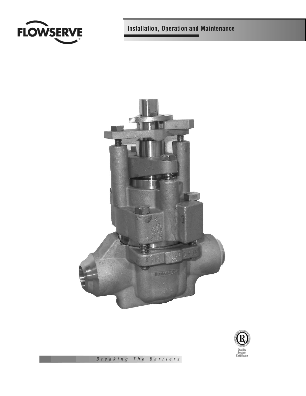
MACH 1 TSQV
SEVERE SERVICE PLUG VALVES
Page 2

FOREWORD
The Flowserve Corporation has established this
Installation, Operating and Maintenance Manual to
facilitate field installation, operation and repair of
Triple Seal Mach 1 Valves
Only Flowserve replacement repair parts and
assembly tooling made or designed by Flowserve
should be used. It is recommended that questions
or concerns involving the processes described in
the manual be directed to the local Sales
Representative of Flowerve Corporation.
TABLE OF CONTENTS
Section Title Page
I. Installation Instructions- Flanged and Welded Valves……………….3
II. Operating Instructions, Parts List & Packing Options………………..4
Ill. Materials, Fastener Torques & Figures………………………………6
IV. Valve Disassembly……………………………………………………..8
V. Valve Assembly 1 "-6"………………………………………………… 9
2
Page 3

SECTION I
INSTALLATION INSTRUCTIONS – FLANGED AND WELDED
TSQV PLUG VALVES
FLANGED:
Installation of Flowserve flanged valves is best accomplished by locating valves in
pipeline flanges, assuring all corrosion and foreign materials are removed from pipe
flange, and then centering the gaskets with the valve flanges. Fasteners or taper
pins should be used to align holes and locate gaskets. Fasteners should be
tightened to the corresponding valve and fastener value.
WELDING:
Flowserve Corporation, Flow Control Division recommends using only qualified
welding procedures and personnel for weld installation of TSQV valves.
The following precautions should be observed:
1. The valve should be inspected prior to welding to assure that no foreign materials
obstruct the flow passageway and that the weld preparation area is free of corrosion
and physical damage.
2. The valve should be in the open position while being welded. Open position is
when the flats on the plug stem are parallel with the pipeline.
3. The TSQV valve contains various sleeve and diaphragm materials that have
different maximum temperature limitations. Refer to Table 1.1 for temperature
limitations.
4. The valve body sleeve and diaphragm area must not exceed these temperatures
during welding. This includes preheats, interpasses or post weld heat treatments, as
applicable. Refer to Figure 2 for locations of the sleeve and diaphragm in the center
valve section
5. Welding of the TSQV Valve without disassembly may be accomplished with no
damage to the sleeve and diaphragm. Precautions MUST be taken to cool the valve
bowl and monitor temperature. The temperature of the center or bowl area of the
valve must not exceed the listed temperature of the material. Valves, sizes two inch
and smaller, must be wrapped with water soaked, fire-resistant material to cool the
valve bowl and inlet where the weld is to be made. Use temperature melt crayons
equal to the sleeve and diaphragm rating to mark the body welding end and monitor
the body temperature. Thermocouples may be attached to the welding end of the
body or surface pyrometers may be used to monitor the body bowl temperature.
CAUTION: DO NOT ALLOW WATER
FROM THE SOAKED WRAPPING
MATERIAL TO ENTER THE
WELDMENT.
Table 1.1 – Temperature Limitations
Material
Description
Temperature
UHMWPE 200°F (93°C)
PFA 500°F (260°C)
FEP and Tefzel 275°F (135°C)
Max.
3
Page 4
SECTION II
OPERATION INSTRUCTIONS AND PARTS LIST FOR TSQV VALVES
Part reference cited in this section can be identified
using Figures 1-3 (Section III) and the material list.
Periodic maintenance requirements for TSQV
valves may vary due to operating conditions
of the process. Factors such as operating
temperature and pressure, flowstream, solid
content, and valve cycles can greatly
influence valve performance and
maintenance requirements. Seal wear and
degradation is compensated by correctly
adjusting appropriate parts. For TSQV valves,
three possible leak paths occur; for each leak
path there exists a means of adjustment.
Leak paths are BONNET, STEM and LINE
(through). Each leak path and corresponding
adjustment shall be treated separately.
I. BONNET
Leakage due to thermal cycling (gradients) and
frequent high pressure cycling is stopped by
snugging the top cap fasteners (item 10) in a
"criss-cross" manner (1-3-2-4) per Fig. 3. This
adjustment is most effective when the valve is not
pressurized. It is important that the top cap
fasteners not be torqued above the level specified
in Tables 1a or 1b.
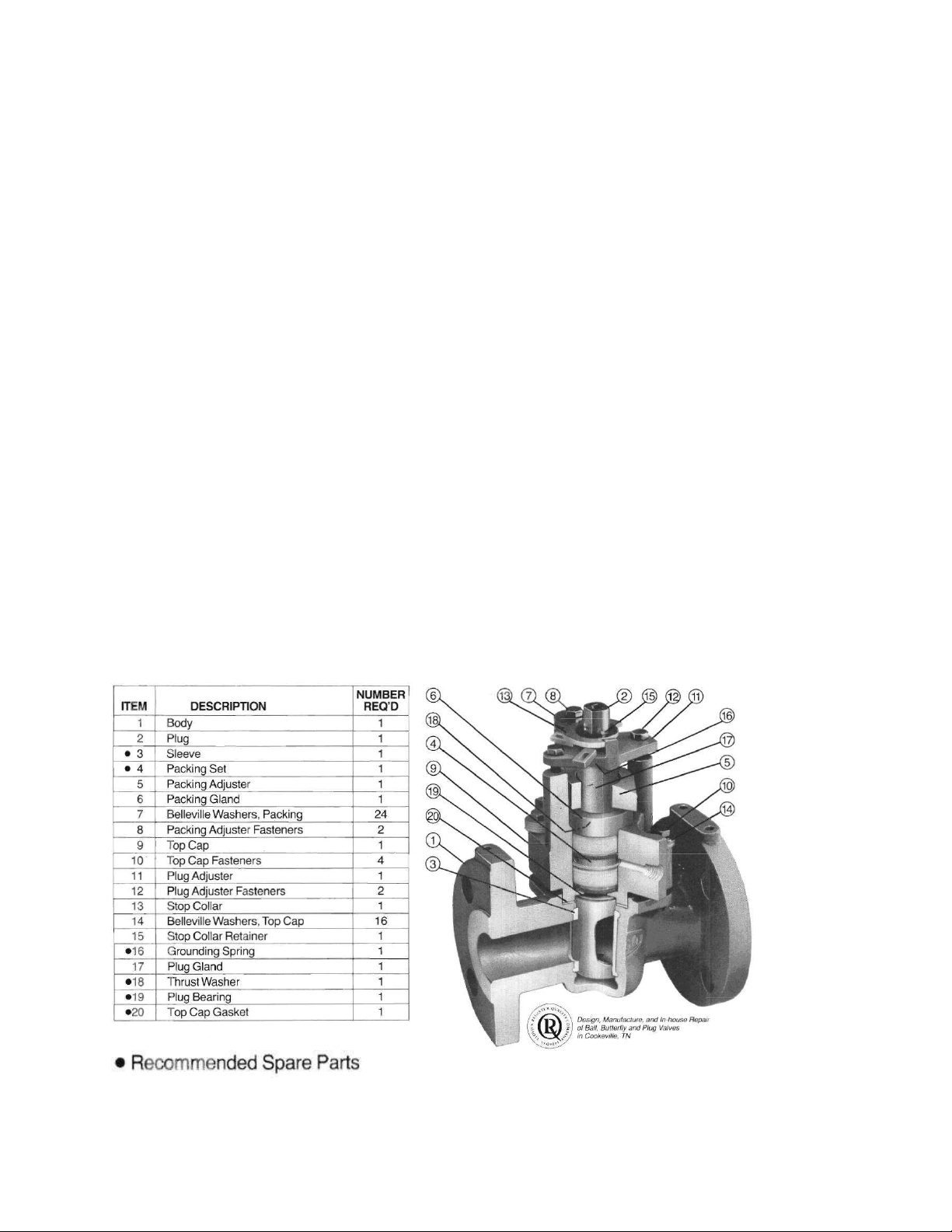
TSQV Assembly and Parts List
2. STEM
Leakage due to wear of the service packing is
stopped by tightening the packing adjuster
fasteners (item 8) in 1/2 turn increments. The
fasteners should be tightened evenly. The
packing adjuster fasteners should not be
tightened above the torque level specified in
Table 3 (pg 6). If possible, the valve should be
operated between adjustments to assure that
the plug stem will not be "frozen" due to
overloading the stem packing. If stem leakage
persists, or the packing adjuster fasteners
bottom out, the stem packing should be
replaced.
3. LINE (through)
Through leakage due to wear or damage to the
valve sleeve, or primary seal can be stopped by
tightening the plug adjuster fasteners (item 12)
in 1/4 turn increments. The fasteners should be
tightened evenly. If possible, the valve should be
operated between adjustments to assure that
the plug has not been forced into the sleeve
excessively, producing an unnecessary high
valve operating torque. Should the valve be
leaking excessively after numerous adjustments,
the sleeve will require replacement.
4
Page 5

Stuffing Box Options:
The Durco TSQV valve will accommodate standard packing of most manufacturers.
A. Standard Polymer Cup and Cone
B. Fire Sealed Options
5
Page 6

SECTION III
MATERIALS, FASTENER TORQUES & FIGURES
Durco Material Code Cross-Reference
6
Page 7

SECTION III (CONT.)
7
Page 8

SECTION IV TSQV VALVE DISASSEMBLY
Recommended Precautionary Measures
1. Valves must be relieved of process fluid and
pressure prior to disassembly. Plug should be in
the open position.
2. Personnel performing disassembly must be
suitably protected and alert for emission of
hazardous process fluid.
3. If there is a pipe plug located at the bottom
bowl of the valve, DO NOT remove the pipe plug
until the valve plug has been removed.
Disassembly Steps
NOTE: Refer to Figures 1-3 for parts
identification. If an actuator or gearbox
operates the valve, alignment marks should
be noted to assure correct orientation when
reassembled. This may best be
accomplished by making matching marks
on the plug stem and operator housing with
no burrs on the plug stem permitted.
1. Gradually loosen plug adjuster fasteners
(Part 12)-DO NOT REMOVE.
2. Turn plug (Part 2) in order to raise the
plug to vent any material trapped in the
valve (see note below). NOTE: If there is
no upward movement of the plug (Part 2),
it will be necessary to devise a method of
lifting the plug upward. This may require
removal of the valve operator (Step 3).
This operation should be undertaken
noting the above precautionary measures.
Methods of plug removal must include
protective measures on plug stem and
plug end.
3. WARNING: Do not loosen or remove top
cap fasteners (Part 10) when removing an
operator or accessory. Remove the
operator by unfastening it from the
bracket.
4. Once the plug (Part 2) has lifted, the
adjuster fasteners (Part 12) can be
completely removed.
5. Loosen and remove the packing adjuster
fasteners (Part 8).
6. Gradually loosen but DO NOT REMOVE
all of the top cap fasteners (Part 10). Turn
the plug until it is loose from the sleeve
(Part 3) and all pressure has been vented.
8
(Again, it may be necessary to use a
mechanical means to move the plug
upwards.)
7. Remove the top cap fasteners (Part 10)
and top cap (Part 9).
8. Remove the plug (Part 2) from the body
(Part 1).
9. Remove the grounding spring (Part 16)
from the plug.
10. lnspect the valve sleeve (Part 3) for
wear or damage, especially scratches
near the top, bottom, and port areas. If
wear or damage is excessive, the sleeve
should be replaced.
11. Remove sleeve (Part 3) as follows:
NOTE: Care should be taken not to
damage the internal body bore.
To remove the sleeve, use a wooden
dowel and pry the sleeve upward by
engaging the dowel in the sleeve at the
top of the port. A sharp blow may be
necessary to unseat the sleeve. Both
sides may need to be pried upward for
removal. (See Figure 4)
12. Thoroughly clean all valve parts with an
acceptable cleaner.
13. lnspect parts for damage. Look for
marred, scratched, or rough sealing
surfaces on the valve plug (Part 2).
NOTE: Reinstallation of damaged or
unclean parts will ruin any replacement
seals installed into the valve.
Figure 4
Page 9

SECTION V
VALVE ASSEMBLY 1”-6” TSQV WITH SLEEVE
NOTE: Part number reference is shown
in Figures 1-3, Sec III.
1. Mount body (Part 1) on arbor press
or table vise holding one flange.
Weld-in bodies are repaired in-line.
Place sleeve (Part 2) in position in
body. Align sleeve ports with body
ports. (Figure 5)
Figure 5
2. Apply a thin film of lubricant on the
plug (Part 2). Then place the plug in
the closed position into the sleeve
which is in the body. (Figure 6).
Figure 6
3. Check that the top seal of the sleeve
is seated into the body counterbore. It
may be necessary to tap sleeve with
soft mallet. Push the plug downward,
while still in the closed position, until
the top of the plug taper is 1/16” above
the top of the sleeve surface. Use an
arbor press or c-clamp. Allow the plug
to remain in this position for time listed
in Table 4. Remove plug.
Table 4
Sleeve Material
UHMWPE, FEP,
Tefzel
PFA
NOTE: After sizing the sleeve, the
TSQV top works are to be assembled
onto the plug prior to pushing the
plug into the sleeved valve body
4. The plug bearing is to be placed on
the plug as shown in Figure 7. The
plug stem and the stuffing box
counterbore of the top cap must be repolished, if necessary, until a surface
finish of 16 RMS is achieved.
5. The top cap is placed on the plug as
shown in Figure 7. Care must be
exercised to insure that the plug stem
is not scratched as the top cap is
lowered onto the plug.
Sizing Time
1"-3" 4"-6"
30 sec 60 sec
5 min 8 min
9
Page 10

6. Install the diaphragm over the plug stem.
The diaphragm guide must be used to
install the diaphragm. Make sure there are
no nicks on the guide. Place the diaphragm
over the guide and push downward over the
guide. See Figure 7. Push the diaphragm
down using the diaphragm pusher.
Figure 7
press is required to load the pusher.)
See Figure 8.
8. At this time, tap pusher with soft
mallet for weld-end valves. Then
apply a light coat of silicone, or
approved lubricant, to the packing
area of the plug stem and the seat
area of the top cap stuffing box.
Figure 8
7. Remove the diaphragm guide and
pusher from the stem. Place the
diaphragm gland over the plug stem.
Now locate and seat the diaphragm
gland by pushing downward with the
diaphragm gland pusher. (An arbor
9. The packing is then placed into the
stuffing box as shown in Figure 9.
Several packing orientations are
shown in an earlier section. Under no
circumstances shall sharp objects
such as screw drivers, cold chisels or
knives be used to force the packing
into the stuffing box. The packing
gland may be used to start the packing
into the stuffing box.
10
Page 11

10. Following insertion of the packing set,
the diaphragm gland pusher is placed
over the plug stem. Seat the packing by
loading the gland pusher with an arbor
press. The packing may be seated in
sections but the gland pusher will only fit a
cone ring. It must not be used to seat
against a cup. See Figure 9. The packing
gland is now placed over the plug stem
and seated with the arbor press.
Figure 9
finger tight. Care should be taken such
that the packing adjuster remains level
with respect to the top cap.
12. The thrust washer is placed over the
plug stem and should lay flat against
the plug stem bearing surface as
shown in Figure 10.
Figure 10
11. The packing adjuster is placed over the
plug stem. Each fastener may have on
optional twelve Belleville washers placed
as shown in Figure 10. The packing
adjuster fasteners should be tightened
13. The plug gland is placed over the
plug stem. Next, the grounding spring
is pushed onto the plug stem. The
adjuster with fasteners is placed over
the plug stem and secured by the
adjuster fasteners shown in Figure 11.
The adjuster fasteners should be
tightened to position the top cap
gasket surface in line with the flat
surface which the plug bearing rests
on as shown in Figure 11.
11
Page 12

Figure 11
Figure 12
14. Place the top cap gasket into the valve
body flange counterbore.
15. Apply a thin, even film of silicone, or
approved lubricant, to the entire outside
surface of the plug taper.
16. The top works are then placed onto the
valve body and oriented as shown in
Figure 12. The plug is then pressed into
the sleeve with the aid of an arbor press
or c-clamp until the top of the plug
adjuster falls ¼’’ below plug adjuster
fasteners. The press must provide
sufficient force to depress the plug,
allowing the gasket surface of the top cap
to bottom against the gasket counterbore.
The valve must remain in the arbor press
for steps 16 thru 19.
17. The top cap fasteners with four optional
Belleville washers each (Figure 12 for top
cap Belleville washer orientation) should
be installed at this time. Do not tighten the
top cap fasteners more than finger tight.
18. Tighten the packing adjuster fasteners
in a manner such that the packing
adjuster does not "tilt". The torque on the
packing adjuster fasteners should be per
Table 3. (Fig 12).
19. Tighten the top cap fasteners in a
crisscross fashion to values listed in
Table 1a or 1b.
20. At this time, remove the valve from
press or c-clamp.
21. Loosen the plug adjuster fasteners
and operate the plug several times.
22. Tighten the plug adjuster fasteners
per Table 2. Install stop collar and
retainer ring.
23. Operate the plug several times. It
will be difficult to turn at first, but will
then loosen and turn freely.
24. Pressure testing of the assembled
valve should be done at this time. Any
additional valve adjustment that might
be needed to hold the specified
pressure should be made at this time.
The valve is now ready for installation
12
 Loading...