

Page 1

USER INSTRUCTIONS
PolyChem S-series pumps
ISO and ANSI
Horizontal, end suction, single stage, centrifugal, chemical
process pumps
PCN=71569207 11-08 (E) (Based on P-30-502-E.)
Original instructions.
Installation
Operation
Maintenance
These instructions must be read prior to installing,
operating, using and maintaining this equipment.
Page 2

USER INSTRUCTIONS POLYCHEM S-SERIES ENGLISH 71569207 11-08
CONTENTS
Page
1 INTRODUCTION AND SAFETY............................4
1.1 General ...........................................................4
1.2 CE marking and approvals..............................4
1.3 Disclaimer .......................................................4
1.4 Copyright.........................................................4
1.5 Duty conditions................................................4
1.6 Safety..............................................................5
1.7 Nameplate and safety labels...........................8
1.8 Specific machine performance........................9
1.9 Noise level.......................................................9
2 TRANSPORT AND STORAGE............................10
2.1 Consignment receipt and unpacking.............10
2.2 Handling........................................................10
2.3 Lifting.............................................................10
2.4 Storage.......................................................... 11
2.5 Recycling and end of product life.................. 11
3 DESCRIPTION....................................................12
3.1 Configurations...............................................12
3.2 Nomenclature................................................ 12
3.3 Design of major parts....................................12
3.4 Performance and operation limits.................13
4 INSTALLATION....................................................14
4.1 Location.........................................................14
4.2 Part assemblies.............................................14
4.3 Foundation....................................................14
4.4 Grouting ........................................................16
4.5 Initial alignment.............................................17
4.6 Piping............................................................ 18
4.7 Electrical connections ...................................23
4.8 Final shaft alignment check ..........................23
4.9 Protection systems........................................ 23
6 MAINTENANCE.................................................. 30
6.1 General......................................................... 30
6.2 Maintenance schedule.................................. 31
6.3 Spare parts ................................................... 31
6.4 Recommended spares
and consumable items ............................... 31
6.5 Tools required............................................... 32
6.6 Fastener torques........................................... 32
6.7 Setting impeller clearance and impeller
replacement................................................32
6.8 Pump removal and disassembly................... 35
6.9 Examination of parts..................................... 37
6.10 Assembly of pump and seal........................ 41
7 FAULTS; CAUSES AND REMEDIES.................. 47
8 PARTS LISTS AND DRAWINGS ........................ 49
8.1 PolyChem S-series....................................... 49
9 CERTIFICATION................................................. 50
10 OTHER RELEVANT DOCUMENTATION
AND MANUALS............................................... 50
10.1 Supplementary User Instructions ............... 50
10.2 Change notes ............................................. 50
10.3 Additional sources of information................ 50
Page
5 COMMISSIONING, STARTUP, OPERATION
AND SHUTDOWN........................................... 24
5.1 Pre-commissioning procedure...................... 24
5.2 Pump lubricants ............................................24
5.3 Impeller clearance......................................... 26
5.4 Direction of rotation.......................................26
5.5 Guarding .......................................................27
5.6 Priming and auxiliary supplies ......................28
5.7 Starting the pump..........................................28
5.8 Running or operation ....................................28
5.9 Stopping and shutdown.................................29
5.10 Hydraulic, mechanical and electrical duty...30
Page 2 of 52 flowserve.com
Page 3

USER INSTRUCTIONS POLYCHEM S-SERIES ENGLISH 71569207 11-08
INDEX
Page
Additional sources of information (10.3).................50
Assembly of pump and seal (6.10).........................41
CE marking and approvals (1.2)...............................4
Certification (9) ....................................................... 50
Change notes (10.2)...............................................50
Configurations (3.1)................................................ 12
Consignment receipt and unpacking (2.1).............. 10
Copyright (1.4).......................................................... 4
Design of major parts (3.3)..................................... 12
Direction of rotation (5.4)........................................ 26
Disclaimer (1.3)......................................................... 4
Duty conditions (1.5)................................................. 4
Electrical connections (4.7) .................................... 23
Examination of parts (6.9) ...................................... 37
Fastener torques (6.6)............................................ 32
Final shaft alignment check (4.8)............................ 23
Foundation (4.3) .....................................................14
Grouting (4.4).......................................................... 16
Guarding (5.5)......................................................... 27
Handling (2.2)......................................................... 10
Hydraulic, mechanical and electrical duty (5.10).... 30
Impeller clearance (5.3)..........................................26
Initial alignment (4.5) ..............................................17
Lifting (2.3)..............................................................10
Location (4.1)..........................................................14
Maintenance schedule (6.2)................................... 30
Nameplate and safety labels (1.7)............................8
Noise level (1.9)........................................................9
Nomenclature (3.2).................................................12
Part assemblies (4.2).............................................. 14
Parts list (8)............................................................. 49
Performance and operation limits (3.4) ..................13
Piping (4.6) ............................................................. 18
Pre-commissioning procedure (5.1) ....................... 24
Priming and auxiliary supplies (5.6)........................ 28
Protection systems (4.9).........................................23
Pump lubricants (5.2) ............................................. 24
Pump removal and disassembly (6.8).................... 35
Recommended spares
and consumable items (6.4).............................. 31
Recycling and end of product life (2.5)...................11
Running or operation (5.8)...................................... 28
Safety (1.6)............................................................... 5
Setting impeller clearance
and impeller replacement (6.7).......................... 32
Spare parts (6.3)..................................................... 31
Specific machine performance (1.8)......................... 9
Starting the pump (5.7)...........................................28
Stopping and shutdown (5.9).................................. 29
Storage (2.4)...........................................................11
Supplementary user instructions (10.1).................. 50
Tools required (6.5) ................................................32
Page 3 of 52 flowserve.com
Page 4
USER INSTRUCTIONS POLYCHEM S-SERIES ENGLISH 71569207 11-08
1 INTRODUCTION AND SAFETY
1.1 General
These instructions must always be kept
close to the product's operating location or
directly with the product.
Flowserve products are designed, developed and
manufactured with state-of-the-art technologies in
modern facilities. The unit is produced with great
care and commitment to continuous quality control,
utilising sophisticated quality techniques and safety
requirements.
Flowserve is committed to continuous quality
improvement and being at service for any further
information about the product in its installation and
operation or about its support products, repair and
diagnostic services.
These instructions are intended to facilitate
familiarization with the product and its permitted use.
Operating the product in compliance with these
instructions is important to help ensure reliability in
service and avoid risks. The instructions may not
take into account local regulations; ensure such
regulations are observed by all, including those
installing the product. Always coordinate repair
activity with operations personnel, and follow all plant
safety requirements and applicable safety and health
laws and regulations.
These instructions must be read prior to
installing, operating, using and maintaining the
equipment in any region worldwide. The
equipment must not be put into service until all
the conditions relating to safety, noted in the
instructions, have been met. Failure to follow and
apply the present user instructions is considered
to be misuse. Personal injury, product damage,
delay or failure caused by misuse are not covered
by the Flowserve warranty.
1.2 CE marking and approvals
It is a legal requirement that machinery and equipment
put into service within certai n regions of t he world shall
conform with the applicable CE Marking Directive s
covering Machinery and, where appli cable, Low V oltage
Equipment, Electromagnetic Compatibility (EMC),
Pressure Equipment Directive (PED) and Equipment for
Potentially Explosive Atmospheres (ATEX).
Where applicable, the Directives and any additional
Approvals, cover important safety aspects relating to
machinery and equipment and the satisfactory provision
of technical documents and safety instructions. Where
applicable this document incorporates information
relevant to these Directives and App rovals.
To confirm the Approvals applying and if the product is
CE marked, check the serial number plate markings
and the Certification. (See section 9, Certificatio n.)
1.3 Disclaimer
Information in these User Instructions is believed
to be reliable. In spite of all the efforts of
Flowserve Corporation to provide sound and all
necessary information the content of this manual
may appear insufficient and is not guaranteed by
Flowserve as to its completeness or accuracy.
Flowserve manufactures products to exacting
International Quality Management System Standards as
certified and audited by external Quality Assurance
organisations. Genuine parts and accessories have
been designed, tested and incorporated into the
products to help ensure their continued product quality
and performance in use. As Flowserve cannot test
parts and accessories sourced fr om other vendo rs the
incorrect incorporation of such parts and accessories
may adversely affect the performance and safety
features of the products. The failure to properly select,
install or use authorised Flow serve parts an d
accessories is considered to be misuse. Damage or
failure caused by misuse is not covere d by the
Flowserve warranty. In addition, any modification of
Flowserve products or removal of original components
may impair the safety of these products in their use.
1.4 Copyright
All rights reserved. No part of these instruction s may be
reproduced, stored in a retrieval syst em or transmitted
in any form or by any means without prior permission of
Flowserve.
1.5 Duty conditions
This product has been selected to meet the
specifications of your purchaser order. The
acknowledgement of these conditions has been sent
separately to the Purchaser. A copy should be kept
with these instructions.
The product must not be operated beyond
the parameters specified for the application.
If there is any doubt as to the suitability of the
product for the application intended, contact
Flowserve for advice, quoting the serial number.
If the conditions of service on your purchase order are
going to be changed (for ex ample li quid pum ped,
temperature or duty) it is requested that the user seeks
the written agreement of Flowserve before start up.
Page 4 of 52 flowserve.com
Page 5
USER INSTRUCTIONS POLYCHEM S-SERIES ENGLISH 71569207 11-08
1.6 Safety
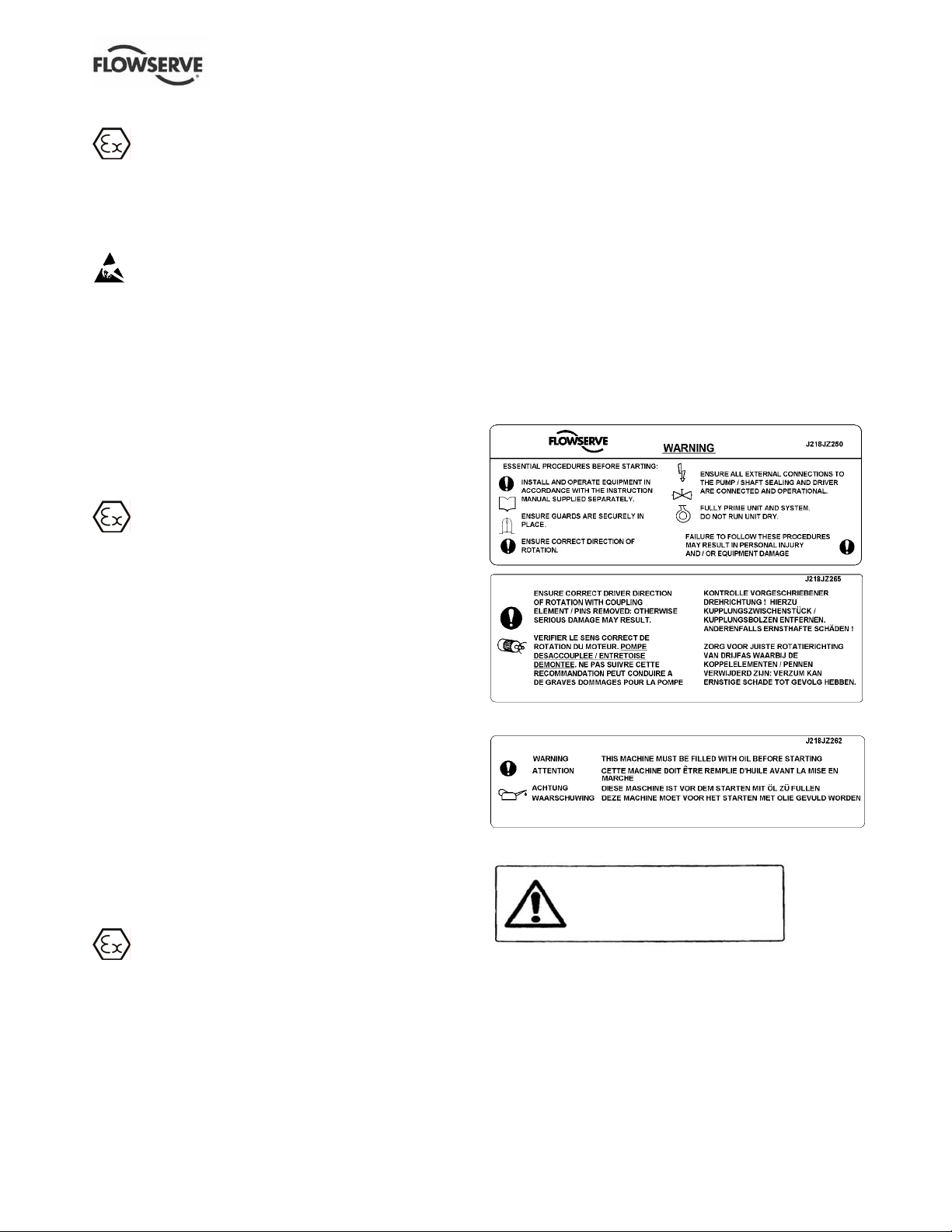
1.6.1 Summary of safety markings
These User Instructions contain specific safety
markings where non-observance of an instruction would
cause hazards. The specific safety markings are:
This symbol indicates electrical safety
instructions where non-compliance will involve a high
risk to personal safety or the loss of life.
This symbol indicates safety instructions where
non-compliance would af fect personal safety and co uld
result in loss of life.
This symbol indicates “hazardous and toxic fluid”
safety instructions where non-compliance would af fect
personal safety and could result in loss of life.
This symbol indi cates safet y inst ruct ions
where non-compliance will involve some risk to safe
operation and personal safety and would dam age the
equipment or property.
This symbol indicates explosive atmosphere zone
marking according to ATEX. It is used in safety
instructions where non-compliance in the hazardous
area would cause the risk of an expl osion.
This symbol is used in safety instructions to
remind not to rub non-metallic surfaces with a dry
cloth; ensure the cloth is damp. It is used in safety
instructions where non-compliance in the hazardous
area would cause the risk of an explosion.
1.6.3 Safety action
This is a summary of conditions and actions to help
prevent injury to personnel and damage to the
environment and to equipment. For prod ucts used
in potentially explosive atmosphere s section 1.6.4
also applies.
NEVER DO MAINTENANCE WORK
WHEN THE UNIT IS CONNECTED TO POWER
DRAIN THE PUMP AND ISOLATE PIPEWORK
BEFORE DISMANTLING THE PUMP
The appropriate safety precautions should be taken
where the pumped liquids are hazardous.
FLUORO-ELASTOMERS (When fitted.)
When a pump has experienced temperatures over
250 ºC (482 ºF), partial decomposition of fluoroelastomers (example: Viton) will occur . In this
condition these are extremely dangerous and skin
contact must be avoided.
HANDLING COMPONENTS
Many precision parts have sharp corners and the
wearing of appropriate safety gloves and equipment
is required when handling these components. To lift
heavy pieces above 25 kg (55 lb) use a crane
appropriate for the mass and in accordance with
current local regulations.
NEVER OPERATE THE PUMP WITHOUT THE
COUPLING GUARD AND ALL OTHER SAFETY
DEVICES CORRECTLY INSTALLED
This sign is not a safety symbol but indicates
an important instructio n in the assembly pro cess.
1.6.2 Personnel qualification and training
All personnel involved in the operation, installation,
inspection and maintenance of the unit must be
qualified to carry out the work involv ed. If the perso nnel
in question do not already possess the necessary
knowledge and skill, appropriate training and inst ruction
must be provided. If required the operator may
commission the manufactur er/sup plier t o provide
applicable training.
Always coordinate repair activity with operations and
health and safety personnel, and follow all plant
safety requirements and applicable safety and health
laws and regulations.
Page 5 of 52 flowserve.com
GUARDS MUST NOT BE REMOVED WHILE
THE PUMP IS OPERATIONAL
HOT (and cold) PARTS
If hot or freezing components or auxiliary heating
supplies can present a danger to operators and
persons entering the immediate area action must be
taken to avoid accidental contact. If complete
protection is not possible, the machine access must
be limited to maintenance staff only, with clear visual
warnings and indicators to those entering the
immediate area. Note: bearing housings must not be
insulated and drive motors and bearings may be hot.
If the temperature is greater than 68 ºC (175 ºF) or
below 5 ºC (20 ºF) in a restricted zone, or exceeds
local regulations, action as above shall be taken.
NEVER APPLY HEAT TO REMOVE IMPELLER
This could damage the liner plus trapped lubricant or
vapor could cause an explosion.
Page 6
USER INSTRUCTIONS POLYCHEM S-SERIES ENGLISH 71569207 11-08
1.6.4 Products used in potentially explosive
THERMAL SHOCK
atmospheres
Rapid changes in the temperature of the liquid within
the pump can cause thermal shock, which can result
in damage or breakage of components and should be
avoided.
The following instructions for pumps and pump
units when installed in potentially explosive
atmospheres must be followed to help ensure
explosion protection. The terminology and
HAZARDOUS LIQUIDS
When the pump is handling hazardous liquids care must
be taken to avoid exposur e to the l iquid by approp riate
siting of the pump, limiting personnel access and by
operator training. If the liquid is flammable and or
explosive, strict safety procedures must be applied.
procedures ensure that the installed pump is in
compliance with the European Directive 94/9/EC,
known as the ATEX Directive, which is mandatory in
Europe and may also be specified in other countries.
Where applicable, both electrical and non-electrical
equipment must meet the requirements 94/9/EC.
Even if the installation is in a region where ATEX is
PREVENT EXCESSIVE EXTERNA L
PIPE LOAD
Do not use pump as a support for piping. Do not mount
expansion joints, u nless all owed by Fl owserve i n writin g,
so that their force, due to internal p ressure, act s on t he
pump flange.
ENSURE CORRECT LUBRICATION
(See section 5, Commissioning, startup, operation
and shutdown.)
NEVER EXCEED THE MAXIMUM
DESIGN PRESSURE (MDP) AT THE TEMPERATURE
SHOWN ON THE PUMP NAMEPLATE
See section 3 for pressure versus temperature
ratings based on the material of construction.
NEVER OPERATE THE PUMP WITH
THE DISCHARGE VALVE CLOSED
(Unless otherwise instructed at a specific point in the
User Instructions.)
(See section 5, Commissioning start-up, operation
and shutdown.)
not the applicable regulation, the general measures
described shall be followed to ensure safe operation.
The measures are explained under the headings of:
• Avoiding excessive surface temperature
• Preventing build up of explosive mixtures
• Preventing the generation of sparks
• Preventing leakages
• Maintaining the pump to avoid hazard
1.6.4.1 Scope of compliance
Use equipment only in the zone for whi ch it is
appropriate. Always check that the driver , drive
coupling assembly, seal and pump equipment are
suitably rated and/or certifie d for the classi fication of the
specific atmosphere in which they are to be inst alled.
Where Flowserve has supplied only the bare shaft
pump, the Ex rating applies only to the pump. The
party responsible for assembling the pump set shall
select the coupling, driver and any additional
equipment, with the necessary CE Certificate/
NEVER RUN THE PUMP DRY OR
WITHOUT PROPER PRIME (Casing flooded)
Declaration of Conformity establishing it is suitable for
the area in which it is to be installed.
NEVER OPERATE THE PUMP WITH
THE SUCTION VALVE CLOSED
It should be fully opened when the pump is running.
The output from a variable frequency drive (VFD) can
cause additional heating effects in the motor and so,
for pumps sets with a VFD, the ATEX Certification for
the motor must state that it is covers the situation
NEVER OPERATE THE PUMP AT
ZERO FLOW OR FOR EXTENDED PERIODS
BELOW THE MINIMUM CONTINUOUS FLOW
where electrical supply is from the VFD. This
particular requirement still applies even if the VFD is
in a safe area.
THE PUMP SHAFT MUST TURN
CLOCKWISE WHEN VIEWED FROM THE MOTOR
END
It is absolutely essential that the rotation of the motor
be checked before installation of the coupling spa cer
and starting the pump. Incorrect rotation of the pump
for even a short period can unscrew the impeller,
which can cause significant damage.
Page 6 of 52 flowserve.com
Page 7
USER INSTRUCTIONS POLYCHEM S-SERIES ENGLISH 71569207 11-08
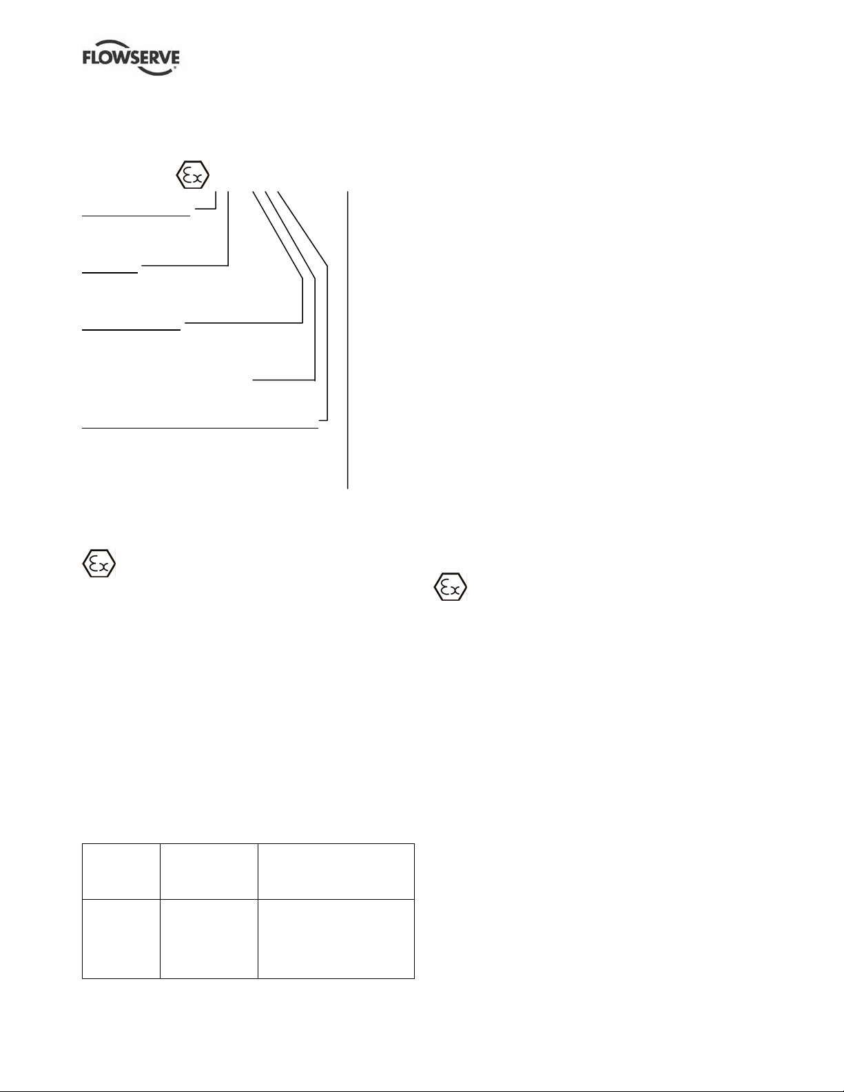
1.6.4.2 Marking
An example of ATEX equipment marking is shown
below. The actual classification of the pump will be
engraved on the nameplate.
II 2 GD c IIC 135 ºC (T4)
Equipment Group
I = Mining
II = Non-mining
Category
2 or M2 = high level protection
3 = normal level of protection
Gas and/or dust
G = Gas
D = Dust
c = Constructional safety
(in accordance with EN13463-5)
Gas Group (Equipment Category 2 only)
IIA – Propane (typical)
IIB – Ethylene (typical)
IIC – Hydrogen (typical)
Maximum surface temperature (Temperature Class)
(see section 1.6.4.3.)
1.6.4.3 Avoiding excessive surface temperatures
ENSURE THE EQUIPMENT TEMPERATURE
CLASS IS SUITABLE FOR THE HAZARD ZONE
Pump liquid temperature
Pumps have a temperature class as stated in the
ATEX Ex rating on the nameplate. These are based
on a maximum ambient of 40 ºC (104 ºF); refer to
Flowserve for higher ambient temperatures.
The surface temperature on the pump is influenced
by the temperature of the liquid handled. The
maximum permissible liquid temperature depends on
the temperature class and must not exceed the
values in the table applicable below. The temperature
rise at the seals and bearings and due to the
minimum permitted flow rate is taken into account in
the temperatures stated.
Temperature
class to
EN13463-1
T6
T5
T4
T3
T2
T1
Maximum
surface
temperature
permitted
85 °C (185 °F)
100 °C (212 °F)
135 °C (275 °F)
200 °C (392 °F)
300 °C (572 °F)
450 °C (842 °F)
Temperature limit of liquid
handled (* depending on
material and construction
variant - check which is lower)
Consult Flowserve
Consult Flowserve
115 °C (239 °F) *
180 °C (356 °F) *
275 °C (527 °F) *
400 °C (752 °F) *
The responsibility for compliance with the
specified maximum liquid temperature is with the
plant operator.
Temperature classification “Tx” is used when the liquid
temperature varies and when the pump is requir ed to be
used in differently classified potentially explosive
atmospheres. In this case the user is responsible for
ensuring that the pump surface temperature does not
exceed that permitted in its actual installe d location.
Do not attempt to check the direction of rotation with the
coupling element/pins fitted due to the risk of sev ere
contact between rotating and stationary compo nents.
Where there is any risk of the pump being run against a
closed valve generating high liqui d and casing exte rnal
surface temperatures it is recommended that users fit
an external surface temperature protectio n device.
Avoid mechanical, hydraulic or electrical overlo ad by
using motor overload trips, temperature monitor or a
power monitor and perform rout ine vibrat ion monito ring.
In dirty or dusty environments, regular checks must
be made and dirt removed from areas around close
clearances, bearing housings and motors.
1.6.4.4 Preventing the build up of explosive
mixtures
ENSURE THE PUMP IS PROPERLY FILLED
AND VENTED AND DOES NOT RUN DRY
Ensure the pump and relevant suction and discharge
pipeline system is totally filled with liquid at all times
during the pump operation, so that an explosive
atmosphere is prevented. In addition it is essential to
make sure that seal chambers, auxiliary shaft seal
systems and any heating and cooling systems are
properly filled.
If the operation of the system cannot avoid this
condition the fitting of an appropriate dry run
protection device is recommended (for example liquid
detection or a power monitor).
To avoid potential hazards from fugitive emissions of
vapor or gas to atmosphere the surrounding area
must be well ventilated.
Page 7 of 52 flowserve.com
Page 8
USER INSTRUCTIONS POLYCHEM S-SERIES ENGLISH 71569207 11-08
1.6.4.5 Preventing sparks
To prevent a potential hazard from mechanical
contact, the coupling guard must be non-sparking.
To avoid the potential hazard from random induced
current generating a spark, the earth contact on the
baseplate must be used.
Avoid electrostatic charge: do not rub no n-metallic
surfaces with a dry cloth; en sure cloth is dam p.
When applicable the coupling must be selected to
comply with 94/9/EC and correct alignment must be
maintained.
Additional requirement for metallic pumps on
non-metallic baseplates
When metallic components are fitted on a nonmetallic baseplate they must be individually earthed.
1.6.4.6 Preventing leakage
The pump must only be used to handle liquids
for which it has been approved to have the correct
corrosion resistance.
Avoid entrapment of liquid in the pump a nd associat ed
piping due to closing of su ction an d discharg e valves,
which could cause dangerous excessiv e pressures to
occur if there is heat input t o the liqu id. This ca n occur if
the pump is stationary or running.
Bursting of liquid containing parts due to freezing
must be avoided by draining or protecting the pump
and ancillary systems.
Where there is the potential hazard of a lo ss of a seal
barrier fluid or external flush, the f luid must be monit ored.
If leakage of liquid to atmosphere can result in a
hazard, the installation of a liquid detection device is
recommended.
1.6.4.7 Maintenance of the centrifugal pump to
avoid a hazard
CORRECT MAINTENANCE IS REQUIRED TO
AVOID POTENTIAL HAZARDS WHICH GIVE A
RISK OF EXPLOSION
The responsibility for compliance of maintenance
and compliance during mainten ance with the
specified product is with the plant operator.
To avoid potential explosion hazards during
maintenance, the tools, cleaning and painting
materials used must not give rise to sparking or
adversely affect the ambient conditions. Where there
is a risk from such tools or materials, maintenance
must be conducted in a safe area.
It is recommended that a maintenance plan and
schedule is adopted. (See section 6, Maintenance.)
1.7 Nameplate and safety labels
1.7.1 Nameplate
For details of nameplate, see the Declaration of
Conformity and section 3.
1.7.2 Safety labels
Oil lubricated units only:
DurcoShieldTM (Splash/Shaft Guard) only:
THIS DEVICE IS NOT A CONTAINMENT
SYSTEM NOR A SEAL BACKUP SYSTEM
IT IS A LIMITED PROTECTION DEVICE.
IT WILL REDUCE BUT NOT ELIMINATE
THE PROBABILITY OF INJURY.
Page 8 of 52 flowserve.com
Page 9

USER INSTRUCTIONS POLYCHEM S-SERIES ENGLISH 71569207 11-08
1.8 Specific machine performance
For performance parameters see section 1.5, Dut y
conditions. Where performance data has been supplied
separately to the purchaser these should be obtained
and retained with these User Inst ructions if re quired.
1.9 Noise level
Attention must be given to the exposure of personnel
to the noise, and local legislation will define when
guidance to personnel on noise limitation is required,
and when noise exposure reduction is mandatory.
This is typically 80 to 85 dBA.
The usual approach is to control the exposure time to
the noise or to enclose the machine to reduce emitted
sound. You may have already specified a limiting
noise level when the equipment was ordered,
however if no noise requirements were defined, then
attention is drawn to the following table to give an
indication of equipment noise level so that you can
take the appropriate action in your plant.
Pump noise level is dependent on a number of
operational factors, flow rate, pipework design and
acoustic characteristics of the building, and so the
values given are subject to a 3 dBA tolerance and
cannot be guaranteed.
Similarly the motor noise a ssumed in t he “pump and
motor” noise is that typically exp ected f rom stand ard
and high efficiency motors when on load dire ctly driving
the pump. Note that a motor driven by an inverter may
show an increased noise at some speeds.
If a pump unit only has been purchased for fitting with
your own driver then the “pump only” noise levels in the
table should be combined with the level for the driver
obtained from the supplier. Consult Flowserv e or a
noise specialist if assistance is required in combining
the values.
It is recommended that where exposure approaches
the prescribed limit, then site noise measurements
should be made.
The values are in sound pressure level L
at 1 m
pA
(3.3 ft) from the machine, for “free field conditions
over a reflecting plane”.
For estimating sound power level L
(re 1 pW) then
WA
add 14 dBA to the sound pressure value.
Motor size
and speed
kW (hp)
<0.55 (<0.75) 72 72 64 65 62 64 62 64
0.75 (1) 72 72 64 66 62 64 62 64
1.1 (1.5) 74 74 66 67 64 64 62 63
1.5 (2) 74 74 66 71 64 64 62 63
2.2 (3) 75 76 68 72 65 66 63 64
3 (4) 75 76 70 73 65 66 63 64
4 (5) 75 76 71 73 65 66 63 64
5.5 (7.5) 76 77 72 75 66 67 64 65
7.5 (10) 76 77 72 75 66 67 64 65
11(15) 80 81 76 78 70 71 68 69
15 (20) 80 81 76 78 70 71 68 69
18.5 (25) 81 81 77 78 71 71 69 71
22 (30) 81 81 77 79 71 71 69 71
30 (40) 83 83 79 81 73 73 71 73
37 (50) 83 83 79 81 73 73 71 73
45 (60) 86 86 82 84 76 76 74 76
55 (75) 86 86 82 84 76 76 74 76
75 (100) 87 87 83 85 77 77 75 77
90 (120) 87 88 83 85 77 78 75 78
110 (150) 89 90 85 87 79 80 77 80
150 (200) 89 90 85 87 79 80 77 80
200 (270)
300 (400) – 87 90 85 86
1 The noise level of machine s in this range will most likely be of valu es which req uire no ise exposure control, but ty pical values are inappropr iate.
Note: for 1 180 and 960 r/min reduce 1 450 r/min values by 2 dBA. For 880 and 720 r/min reduce 1 450 r/min values by 3 dBA.
3 550 r/min 2 900 r/min 1 750 r/min 1 450 r/min
Pump
only
1
Pump and
Typical sound pressure level LpA at 1 m reference 20 µPa, dBA
motor
1
1 1
Pump
only
Pump and
motor
Pump
only
85 87 83 85
Pump and
motor
Pump
only
Pump and
motor
Page 9 of 52 flowserve.com
Page 10
USER INSTRUCTIONS POLYCHEM S-SERIES ENGLISH 71569207 11-08
2 TRANSPORT AND STORAGE
2.1 Consignment receipt and unpacking
Immediately after receipt of the equipment it must be
checked against the delivery/shipping documents for
its completeness and that there has been no damage
in transportation. Any shortage and or damage must
be reported immediately to Flowserve and must be
received in writing within thirty (30) calendar days of
receipt of the equipment. Later claims cannot be
accepted.
Check any crate, boxes or wrappings for any
accessories or spare parts that may be packed
separately with the equipment or attached to side
walls of the box or equipment.
Each product has a unique serial number. Check
that this number corresponds with that advised and
always quote this number in correspondence as well
as when ordering spare parts or further accessories.
2.2 Handling
Boxes, crates, pallets or cartons may be unloaded
using fork lift vehicles or slings dependent on their
size and construction.
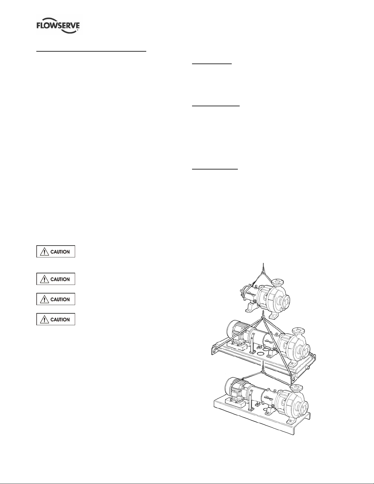
2.3 Lifting
Pumps and motors often have integral
lifting lugs or eye bolts. These are intended for use in
only lifting the individual piece of equipment.
2.3.1.3 Bearing housing [3200]
Group A and 1
lower support ribs between the housing barrel an d
the casing attachment flange. Use a choker hitch
when slinging. (Make sure there are no sharp edges
on the bottom side of the ribs that could cut the sling.)
Group B, C and 2
through the lifting lug located on the top of the
housing.
2.3.1.4 Power end
Same as bearing housing.
2.3.1.5 Bare pump
Horizontal pumps
nozzle and around the outboar d end of th e bearing
housing with separate slings. Choker hitches must be
used at both attachment points and pulled tight. Make
sure the completion of the choker hitch on the discharge
nozzle is toward the coupling end of the pump shaft as
shown in Figure 2-1. The sling lengths should be
adjusted to balance th e load bef ore att achi ng the lift ing
hook. Pump models with non standard flanges can not
accommodate a sling around the discharge nozzle;
when lifting these pumps an in dividual trai ned in
properly lifting equipment must be consulted.
Figure 2-1
: insert a sling between the upper and
: insert either a sling or hook
: sling around the pump discharge
Do not use eye bolts or cast-in lifting
lugs to lift pump, motor and baseplate assemblies.
To avoid distortion, the pump unit
should be lifted as shown.
Care must be taken to lift components or
assemblies above the center of gr avity to prev ent the
unit from flipping. This is especially t rue with In -Line
pumps.
2.3.1 Lifting pump components
2.3.1.1 Casing [1100]
Use a choker hitch pulled tight around the discharge
nozzle.
2.3.1.2 Rear cover [1220]
Insert an eye hook in the drilled and tapped hole on
the face of the cover. Use either a sling or hook
through the eye bolt.
Page 10 of 52 flowserve.com
Page 11
USER INSTRUCTIONS POLYCHEM S-SERIES ENGLISH 71569207 11-08
2.3.2 Lifting pump, motor and baseplate assembly
If the baseplate has lifting holes cut in the sides at the
end (Type D and Type E base s) insert lifti ng S hook s at
the four corners and use slings or chains to connect to
the lifting eye. (Figure 2-1.) Do not use slings through
the lifting holes.
For other baseplates, sling around the pump discharge
nozzle, and around the outboard end of the motor
frame using choker hitches pulled tight. Pump models
with non standard flanges can not accommodate a
sling around the discharge nozzle; when lifting these
pumps an individual trained in properly lifting
equipment must be consulted. (Figure 2-1.)
The sling should be positioned so the weight is not
carried through the motor fan housing. Make sure the
completion of the choker hitch on the discharge
nozzle is toward the coupling end of the pump shaft
as shown in Figure 2-1.
2.4 Storage
Store th e pump in a clea n, dry locati on
away from vibration. Leave piping connectio n covers in
place to keep dirt and other foreign material out of pump
casing. T urn pump at int erv als to pr event brinel ling of
the bearings and the seal faces, if fitted, from sticking.
The pump may be stored as above for up to 6
months. Consult Flowserve for preservative actions
when a longer storage period is needed.
2.4.1 Short term storage and packaging
Normal packaging is designed to protect the pump
and parts during shipment and for dry, indoor storage
for up to six months or less. The following is an
overview of our normal packaging:
• All loose unmounted items are packaged in a
water proof plastic bag and placed under the
coupling guard
• Inner surfaces of the bearing housing, shaft (area
through bearing housing) and bearings are coated
with Cortec VCI-329 rust inhibitor, or equal.
2.4.2 Long term storage and packaging
Long term storage is defined as more than six
months, but less than 12 months. The procedure
Flowserve follows for long term storage of pumps is
given below. These procedures are in addition to the
short term procedure.
• Each assembly is hermetically (heat) sealed from
the atmosphere by means of tack wrap sheeting
and rubber bushings (mounting holes)
• Desiccant bags are placed inside the tack
wrapped packaging
• A solid wood box is used to cover the assembly
This packaging will provide protection for up to twelve
months from humidity, salt laden air, dust etc.
After unpacking, protection will be the responsibility of
the user. Addition of oil to the bearing housing will
remove the inhibitor. If unit s are to be idle fo r extende d
periods after addition of lubricants, in hibitor oils a nd
greases should be used. Every three months, the pump
shaft should be rotated approximately 10 revolution s.
2.5 Recycling and end of product life
At the end of the service life of the product or its
parts, the relevant materials and parts should be
recycled or disposed of using an environmentally
acceptable method and local requirements. If the
product contains substances that are harmful to the
environment, these should be removed and disposed
of in accordance with current regulations. This also
includes the liquids and/or gases that may be used in
the "seal system" or other utilities.
Make sure that hazardous substances are
disposed of safely and that the correct personal
protective equipment is used. The safety
specifications must be in accordance with the current
regulations at all times.
Bearing housings are not filled with oil
prior to shipment
• Regreasable bearings are packed with grease
(MOBIL POLYREX EM)
• Exposed shafts are taped with Polywrap
• Flange covers are secured to both the suction
and discharge flanges
• In some cases with assemblies ordered wit h
external piping, components may be
disassembled for shipment
• The pump must be stored in a covered, dry location
Page 11 of 52 flowserve.com
Page 12

USER INSTRUCTIONS POLYCHEM S-SERIES ENGLISH 71569207 11-08
3 DESCRIPTION
3.1 Configurations
PolyChem S-series chemical process pumps are
horizontal, end suction, single stage, centrifugal
pumps. The ISO version of this pump conforms
dimensionally to ISO 2858/5199 while the ANSI
model agrees dimensionally with ASME B73.1. Both
have centerline discharge.
3.2 Nomenclature
The pump size will be engraved on the nameplate
typically as below:
PS 40 – 200 / 190CL (ISO)
PS 2 x 1 - 10 / 8.25CL (ANSI)
P = PolyChem pump line
S = Sealed
Power end:
Mark 3A – Standard
ANSI 3A – Optional (lifetime guarantee)
ISO pump:
“40” = Nominal discharge port size (mm)
“200” = Nominal (max.) impeller diameter (mm)
“190” =Actual impeller diameter (mm)
ANSI pump:
“2” = Nominal suction port size (in.)
“1” = Nominal discharge port size (in.)
“10” = Nominal (max) impeller diameter (in.)
“8.25” = Actual impeller diameter (in.)
Impeller style (ISO or ANSI):
CL = closed vane impeller
OP = Open impeller
Pump design variation (ANSI only):
HD = Heavy duty shaft which is available on all Group 2
pump models. The shaft increases from
47.63 mm (1.875 in.) to 53.98 mm (2.125 in.).
An example of the nameplate used on the PolyChem
pump is shown in Figure 3-1. This nameplate is
always mounted on the bearing housing.
Figure 3-1: Nameplate mounted to housing
Serial No.
Equipment No.
Purchase Order
Model
Material
Date DD/MMM/YY
Size
PS 2 X 1 - 10 / 8.25CL
MDP
3.3 Design of major parts
3.3.1 Pump casing
Removal of the casing is not required when
performing maintenance of the rotating element. The
rotating element is easily removed (back pull out).
3.3.2 Impeller
Depending on the pump size, the impeller is either
closed vane or open.
3.3.3 Shaft/sleeve
Solid and sleeved shafts are available, supported on
bearings, threaded impeller end and keyed drive end.
3.3.4 Pump bearings and lubrication
Ball bearings are fitted as standard and may be either
oil or grease lubricated.
3.3.5 Bearing housing
Large oil bath reservoir.
3.3.6 Seal chamber (cover plate)
The seal chamber has a spigot (rabbet) fit between
the pump casing and bearing housing (adapter) for
optimum concentricity. The design enables a number
of sealing options to be fitted.
3.3.7 Shaft seal
The mechanical seal(s), attached to the pump shaft,
seals the pumped liquid from the environment.
3.3.8 Driver
The driver is normally an electric motor. Different drive
configurations may be fitted such as internal combustion
engines, turbines, hydraulic motors et c drivin g via
couplings, belts, gearboxes, drive shafts etc.
3.3.9 Accessories
Accessories may be fitted when specified by the
customer.
Page 12 of 52 flowserve.com
Page 13

USER INSTRUCTIONS POLYCHEM S-SERIES ENGLISH 71569207 11-08
3.4 Performance and operation limits
This product has been selected t o meet th e
specification of your purchase order. See section 1.5.
The following data is included as additional information
3.4.2 Pressure-temperature ratings
PN 16 flanges are standard for the ISO model pump
while Class 150 flanges are standard for the ANSI
model. Refer to Figure 3-3A and 3-3B for each
pump’s pressure-temperature (P-T) ratings.
to help with your installation. It is typical, and factors
such as liquid being pumped, temperature, material of
construction, and seal type may influence this data. If
required, a definitive statement fo r your appli cation can
be obtained from Flowserve.
3.4.1 Material cross reference chart
Figure 3-2 is the material cross-reference chart for all
PolyChem S-series pumps.
The maximum discharge pressure must be less
than or equal to the P-T rating. Discharge pressure
may be approximated by adding the suction pressure
to the differential pressure developed by the pump.
3.4.3 Suction pressure limits
The suction pressure limits for PolyChem S-series
pumps are limited by the P-T rating.
Figure 3-2: Material cross-reference chart
Flowserve
material code
Z0L48 PFA lined Ductile iron (cast) DIPA None Note 1 1.0
E2025 Ductile Iron Casting 7043 None EN1563, Gr. JS 1025 1.0
E3020 Ductile Iron Casting DCI None A395, Gr. 60-40-18 1.0
D0005 Carbon Steel SR None N/A
D2044 Quenched and Tempered Steel CK45 None EN 10083-1 N/A
D3013 1018 Carbon Steel Z None N/A
D3058 304 Stainless Steel 304 None A276, Type 304 N/A
D3277 Carbon Steel BB 1144 UNS G11440 N/A
E2008 Ductile Iron Casting 7040 None EN1563, Gr. JS 1030 N/A
E3006 Cast Iron Casting CI None A48, Gr. 25A N/A
E3035 Ductile Iron Casting DCI2 None A536, Gr. 65-45-12 N/A
E4034 Ductile Iron Casting DCI4 None Note 2 N/A
I3011 Titanium TIW B348, Gr. 3 N/A
J0020 Sintered silicon carbide SC3 None None N/A
K3019 Hastelloy C276 C276 C276 UNS N10276 N/A
K4008 Chlorimet 3 DC3 Hastelloy® C A494, Gr. CW6M N/A
L0009 Carbon Filled Teflon TFEC None N/A
L1010 Ethylene Propylene Diene Monomer EPDM None N/A
L1011 Viton VA None N/A
L1017 Nitrile Butadiene Rubber NBR None N/A
L1049 Kalrez 4079 KAL None N/A
L1103 Pollyulphone PS None N/A
M1001 ISO 3506 Grade A2 Class 70 A270 None N/A
M1006 ISO898 QT 12.9 None N/A
M1013 ISO 898/1 Class 8.8 88 None N/A
Z0067 Protective Plated Carbon Steel SRCD None N/A
Z0L49 PFA lined carbon steel (wrought) SRPA None N/A
Z0L52 Carbon filled fluoropolymer CFTM None N/A
Z0L53 Carbon fiber reinforced PFA CRPA None N/A
Z0L59 1018 (SR) welded to 316 (SS) ZH None N/A
Z0L60 1018 (SR) welded to C20 (Alloy 20) ZC20 None N/A
Z0L61 304 (SS) welded to B2 (B2) EHB None N/A
Z0L62 304 (SS) welded to C276 (C276) EHC None N/A
Z0L64 Teflon lined A193, Gr. B7 B7TF None N/A
Z0L65 Teflon lined A194, Gr. 2H SRTF None N/A
Z0L72 Teflon – Silicon Rubber – Carbon Steel TSSR None N/A
Z0M21 PFA lined stainless steel (cast) D4PA None N/A
Z0M22 Viton – Carbon Steel VSR None N/A
Z0M35 Carbon fiber reinforced fluoropolymer CRTM None N/A
®Hastelloy is a registered trademark of Haynes International, Inc.
Note 1. The casting used for ISO pumps is E2025 and for ANSI pumps is E3020
Note 2. Dual Spec. EN1563 Gr. JS1030 & A536 Gr. 65-45-12
Designation
Durco
legacy
codes
Equivalent
wrought
designation
EN/ASTM
specifications
Nozzle load
material group
Page 13 of 52 flowserve.com
Page 14

USER INSTRUCTIONS POLYCHEM S-SERIES ENGLISH 71569207 11-08
Figure 3-3A: Pressure-temperature rating
(ISO pump with PN 16 flanges – Material Group No. 1.0)
Temperature
°C ( °F)
Bar
(psi)
-29
(-20)
16
(232)
-18
(0)
16
(232)
38
(100)
16
(232)
93
(200)
16
(232)
121
(250)
16
(232)
149
(300)
15.5
(225)
Figure 3-3B: Pressure–temperature rating
(ANSI pump with Class 150 flanges – Material Group
No. 1.0)
Temperature
°C ( °F)
Bar
(psi)
-29
(-20)
17.2
(250)
-18
(0)
17.2
(250)
38
(100)
17.2
(250)
93
(200)
16.2
(235)
149
(300)
14.8
(215)
3.4.4 Minimum continuous flow
The minimum continuous flow (MCF) is based on a
percentage of the best efficiency point (BEP). Figure
3-4 identifies the MCF for all PolyChe m S-serie s pump s.
Figure 3-4: Minimum continuous flow
n/a
n/a
n/a
n/a
MCF % of BEP
1 750/1 450
r/min
10 % 10 %
10 % 10 %
20 % 10 %
40 % 10 %
1 180/960
r/min
Pump size
PS3x2-6 20 % 10 % 10 %
PS3x2-10
PS50-250
PS4x3-10
PS65-250
PS3x2-13
PS50-315
PS4x3-13
PS65-315
PS6x4-13HD
PS100-315
All other sizes
3 500/2 900
r/min
30 % 10 % 10 %
10 % 10 % 10 %
4 INSTALLATION
Equipment operated in hazardous locations
must comply with the relevant explosion protection
regulatiuons. See section 1.6.4, Products used in
potentially explosive atmospheres.
4.1 Location
The pump should be located to allow room for acce ss,
ventilation, maintenance, and inspe ction with ample
headroom for lifting and should be as close as
practicable to the supply of liquid to be pumped.
Refer to the general arrangement drawing for the
pump set.
4.2 Part assemblies
The supply of motors and baseplates are optional.
As a result, it is the responsibility of the installer to
ensure that the motor is assembled to the pump and
aligned as detailed in section 4.5 and 4.8.
4.3 Foundation
4.3.1 Protection of openings and threads
When the pump is shipped, all threads and all
openings are covered. This protection/covering
should not be removed until installation. If, for any
reason, the pump is removed from service, this
protection should be reinstalled.
4.3.2 Rigid baseplates - overview
The function of a baseplate is to provide a rigid
foundation under a pump and its driver that maintains
alignment between the two. Baseplates may be
generally classified into two types:
• Foundation-mounted, grouted de sign. (Figure 4-1. )
• Stilt mounted, or free standing. (Figure 4-2.)
Figure 4-1
Figure 4-2
Baseplates intended for grouted installation are
designed to use the grout as a stiffening member.
Stilt mounted baseplates, on the other hand, are
designed to provide their own rigidity. Therefore the
designs of the two baseplates are usually different.
Regardless of the type of baseplate used, it must
provide certain functions that ensure a reliable
installation. Three of these requirements are:
• The baseplate must provide sufficient rigidity to
assure the assembly can be transported and
installed, given reasonable care in handling,
without damage. It must also be rigid enough
when properly installed to resist operating loads.
• The baseplate must provide a reasonably flat
mounting surface for the pump and driver.
Uneven surfaces will result in a soft-foot condition
that may make alignment difficult or impossible.
Page 14 of 52 flowserve.com
Page 15
USER INSTRUCTIONS POLYCHEM S-SERIES ENGLISH 71569207 11-08
Experience indicates that a baseplate with a top
surface flatness of 1.25 mm/m (0.015 in./ft) across
the diagonal corners of the baseplate provides
such a mounting surface. Therefore, this is the
tolerance to which we supply our standard
baseplate. Some users may desire an even flatter
surface, which can facilitate installation and
alignment. Flowserve will supply flatter baseplates
upon request at extra cost. For example,
mounting surface flatness of 0.17 mm/m
(0.002 in./ft) is offered on the Flowserve Type E
“Ten Point” baseplate shown in Figure 4-1.
• The baseplate must be designed to allow the user
to final field align the pump a nd drive r to within th eir
own particular standards and to compensate for
any pump or driver movement that occurred during
handling. Normal industry practice is to achieve
final alignment by moving the motor to match the
pump. Flowserve practice is to confir m in our shop
that the pump assembly can be accurately aligned.
Before shipment, the factory verifies that there is
enough horizontal movement capability at the motor
to obtain a “perfect” final alig nment wh en the
installer puts the baseplate assembly into its
original, top levelled, unstressed conditi on.
4.3.3 Stilt and spring mounted baseplates
Flowserve offers stilt and spring mounted baseplates.
(See Figure 4-2 for stilt mounted option.) The low
vibration levels of PolyChem pumps allow the use of
these baseplates - provided they are of a rigid design.
The baseplate is set on a flat surface with no tie down
bolts or other means of anchoring it to the floor.
General instructions for assembling these baseplates
are given below. For dimensional information, please
refer to the appropriate Flowserve “Sales print”.
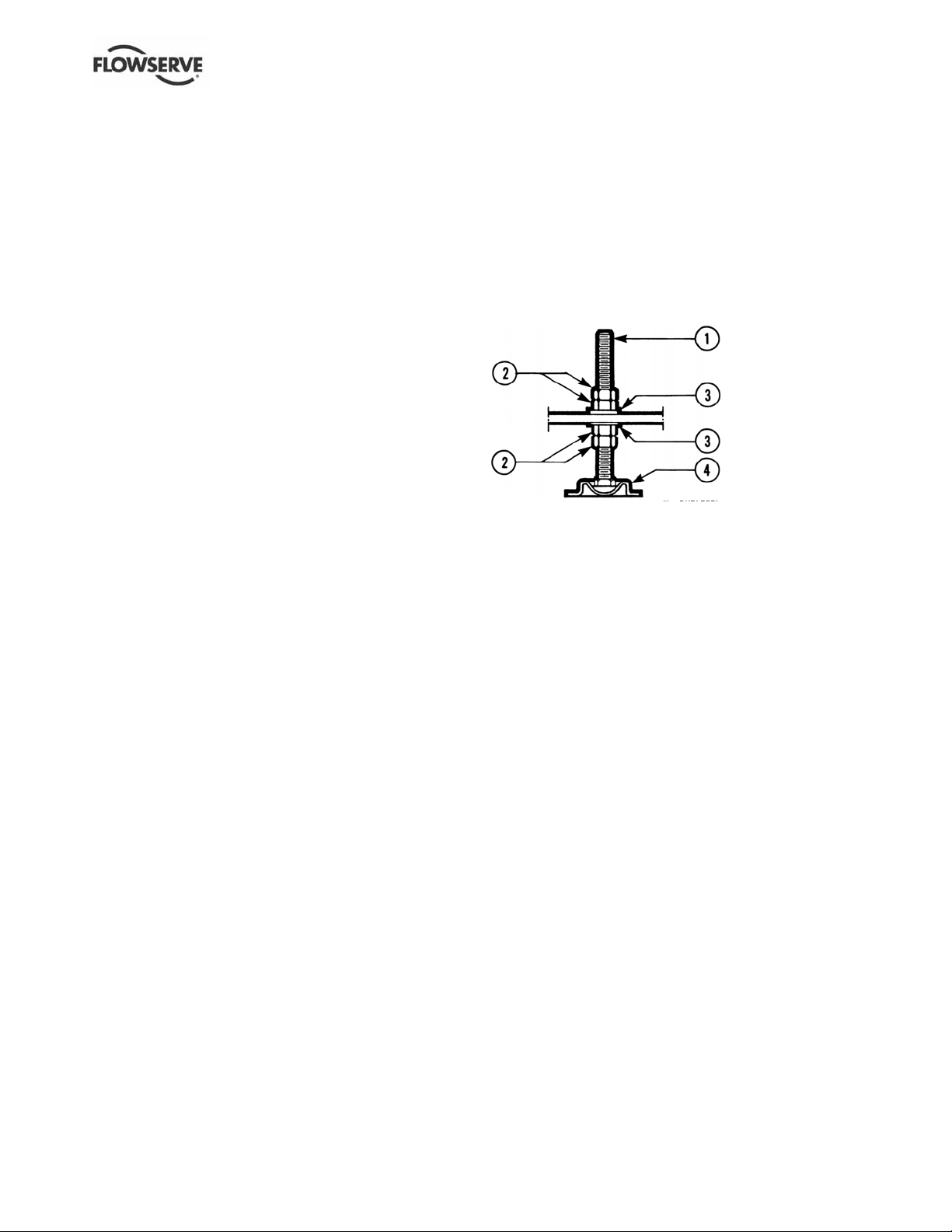
4.3.3.1 Stilt mounted baseplate assembly
instructions
Refer to Figure 4-3.
a) Raise or block up baseplate/pump above the floor
to allow for the assembly of the stilts.
b) Predetermine or measure the approximate
desired height for the baseplate above the floor.
c) Set the bottom nuts [2] above the stilt bolt head
[1] to the desired height.
d) Assemble lock washer [3] down over the stilt bolt.
e) Assemble the stilt bolt up through hole in the
bottom plate and hold in place.
f) Assemble the lock washer [3] and nut [2] on the stilt
bolt. Tighten the nut down on the lock washer.
g) After all four stilts have been assembled, position
the baseplate in place, over the floor cups [4]
under each stilt location, and lower the baseplate
to the floor.
h) Level and make final height adjustments to the
suction and discharge pipe by first loosening the
top nuts and turning the bottom nuts to raise or
lower the baseplate.
i) Tighten the top and bottom nuts at the lock
washer [3] first then tighten the other nuts.
j) It should be noted that the connecting pipelines
must be individually supported, and that the stilt
mounted baseplate is not intended to support
total static pipe load.
Figure 4-3
1. Stilt bolt
2. Nuts
3. Lock washer
4. Floor cup
4.3.3.2 Stilt/spring mounted baseplate assembly
instructions
Refer to Figure 4-4.
a) Raise or block up baseplate/pump above the floor
to allow for the assembly of the stilts.
b) Set the bottom nuts [4] above the stilt bolt head [1].
This allows for 51 mm (2 in.) upwa rd movement f or
the final height adjustment o f the suctio n/discha rge
flange.
c) Assemble the lock washer [6] flat washer [5] and
bottom spring/cup assembly [2] down over the
stilt bolt [1].
d) Assemble the stilt bolt/bottom spring up through
hole in the bottom plate and hold in place.
e) Assemble top spring/cup assembly [3] down over
stilt bolt.
f) Assemble flat washer [5], lock washer [6] and
nuts [4] on the stilt bolt.
g) Tighten down top nuts, compressing the top
spring approximately 13 mm (0.5 in.). Additional
compression may be required to stabilize the
baseplate.
h) After all four stilts have been assembled, position
the baseplate in place, over the floor cups [7]
under each stilt location, and lower the baseplate
down to the floor.
i) Level and make final height adjustments to the
suction and discharge pipe by first loosening the
top nuts, and turning the bottom nuts to raise or
lower the baseplate.
j) Recompress the top spring to the compression
established in step g) and lock the nuts.
Page 15 of 52 flowserve.com
Page 16

USER INSTRUCTIONS POLYCHEM S-SERIES ENGLISH 71569207 11-08
t
k) It should be noted that the connecting pipelines
must be individually supported, and that the
spring mounted baseplate is not intended to
support total static pipe loads.
Figure 4-4
1 in. (25 mm) approx. i nitial heigh
1 . Sti l t bo l t
2. Bott om spring [ 3¼ in.
(83 mm ) O/D x 4 in.
(102 mm) floor cups]
3. Top spring [2 in.
(51 m m) O/D x 4 in.
(102 mm) floor cups]
4. Nuts
5. Flat washer
6. Loc k was her
7. Floor cup
4.3.3.3 Stilt/spring mounted baseplates - motor
alignment
The procedure for motor alignment on stilt or spring
mounted baseplates is similar to grouted baseplates.
The difference is primarily in the way the baseplate is
levelled.
a) Level the baseplate by using the stilt adjusters.
(Shims are not needed as with grouted baseplates.)
b) After the base is level, it is locked in place by
locking the stilt adjusters.
c) Next the initial pump alignment must be checked.
The vertical height adjustment provided by the
stilts allows the possibility of slightly twisting the
baseplate. If there has been no transit damage
or twisting of the baseplate during stilt height
adjustment, the pump and driver should be within
0.38 mm (0.015 in.) parallel, and 0.0025 mm/mm
(0.0025 in./in.) angular alignment. If this is not
the case, check to see if the driver mounting
fasteners are centered in the driver feet holes.
d) If the fasteners are not centered there was likely
shipping damage. Re-center the fasteners and
perform a preliminary alignment to the above
tolerances by shimming under the motor for
vertical alignment, and by moving the pump for
horizontal alignment.
e) If the fasteners are centered, then the baseplate
may be twisted. Slightly adjust (one turn of the
adjusting nut) the stilts at the driver end of the
baseplate and check for alignment to the above
tolerances. Repeat as necessary while
maintaining a level condition as measured from
the pump discharge flange.
f) Lock the stilt adjusters.
The remaining steps are as listed for new grouted
baseplates.
4.4 Grouting
a) The pump foundation should be located as close to
the source of the fluid to be pumped as practical.
b) There should be adequate space for workers to
install, operate, and maintain the pump. The
foundation should be sufficient to absorb any
vibration and should provide a rigid support for
the pump and motor.
c) Recommended mass of a concrete foundation
should be three times that of the pump, motor
and base. Refer to Figure 4-5.
Foundation bolts are imbedded in the
concrete inside a sleeve to allow some
movement of the bolt.
Figure 4-5
d) Level the pump baseplate assembly. If the
baseplate has machined coplanar mounti ng
surfaces, these machined surfaces are to be
referenced when leveling the baseplate. This may
require that the pump and motor b e remove d from
the baseplate in order to reference the machined
faces. If the baseplate is without machined
coplanar mounting surfaces, the pump and motor
are to be left on the baseplate. The p roper surfa ces
to reference when leveling the pump baseplate
assembly are the pump suction and discharge
flanges. DO NOT stress the baseplate.
e) Do not bolt the suction or discharge flanges of the
pump to the piping until the ba seplate f oundati on is
completely installed. If equipped, use leveling
jackscrews to level the baseplate. If jackscrews are
not provided, shims and wedges should be used.
(See Figure 4-5.) Check for levelne ss in both the
longitudinal and lateral directions. Shims should be
placed at all base anchor bolt locations, and in the
middle edge of the base if the base i s more than
1.5 m (5 ft.) long. Do not rely on th e bottom of t he
baseplate to be flat. Standard baseplate bottoms
are not machined, and it is not likely that the field
mounting surface is flat.
Page 16 of 52 flowserve.com
Page 17

USER INSTRUCTIONS POLYCHEM S-SERIES ENGLISH 71569207 11-08
f) After leveling the baseplate, tighten the anchor
bolts. If shims were used, make sure that the
baseplate was shimmed near each anchor bolt
before tightening. Failure to do this may result in
a twist of the baseplate, which could make it
impossible to obtain final alignment.
g) Check the level of the baseplate to make sure
that tightening the anchor bolts did not disturb the
level of the baseplate. If the anchor bolts did
change the level, adjust the jackscrews or shims
as needed to level the baseplate.
h) Continue adjusting the jackscrews or shims and
tightening the anchor bolts until the baseplate is
level.
i) Check initial alignment. If the pump and motor
were removed from the baseplate proceed with
step j) first, then the pump and motor should be
reinstalled onto the baseplate using Flowserve’s
factory preliminary alignment procedure as
described in section 4.5, and then continue with
the following. As descri bed above, pumps are
given a preliminary alignment at t he fact ory. Thi s
preliminary alignment is done in a way that ensures
that, if the installer duplicates the factory conditions,
there will be sufficient clearance between the motor
hold down bolts and motor foot hol es to move the
motor into final alignment. If the pump and motor
were properly reinstalled to the baseplate or if they
were not removed from the baseplate and there has
been no transit damage, and also if the above steps
where done properly, the pump and driver shoul d
be within 0.38 mm (0.015 in.) FIM (Full Indicator
Movement) parallel, and 0.0025 mm/mm (0.0025
in./in.) FIM angular. If this is not the case, first
check to see if the driver mounting fasteners are
centered in the driver feet holes. If not, re-center
the fasteners and perform a preliminary alignment
to the above tolerances by shimming under the
motor for vertical alignment, and by m oving the
pump for horizontal alignment.
j) Grout the baseplate. A non-shrinking grout
should be used. Make sure that the grout fills the
area under the baseplate. After the grout has
cured, check for voids and repair them.
Jackscrews, shims and wedges should be
removed from under the baseplate at this time. If
they were to be left in place, they could rust,
swell, and cause distortion in the baseplate.
k) Run piping to the suction and discharge of the
pump. There should be no piping loads
transmitted to the pump after connection is made.
Recheck the alignment to verify that there are no
significant loads.
4.5 Initial alignment
4.5.1 Horizontal initial alignment procedure
The purpose of factory alignment is to ensure that the
user will have full utilization of the clearance in the
motor holes for final job-site alignment. To achieve
this, the factory alignment procedure specifies that
the pump be aligned in the horizontal plane to the
motor, with the motor foot bolts centered in the motor
holes. This procedure ensures that there is sufficient
clearance in the motor holes for the customer to field
align the motor to the pump, to zero tolerance. This
philosophy requires that the customer be able to
place the base in the same condition as the factory.
Thus the factory alignment will be done with the base
sitting in an unrestrained condition on a flat and level
surface. This standard also emphasizes the need to
ensure the shaft spacing is adequate to accept the
specified coupling spacer.
The factory alignment procedure is summarized below:
a) The baseplate is placed on a flat and level
workbench in a free and unstressed position.
b) The baseplate is levelled as necessary. Levelling
is accomplished by placing shims under the rails
of the base at the appropriate anchor bolt hole
locations. Levelness is checked in both the
longitudinal and lateral directions.
c) The motor and appropriate motor mounting
hardware is placed on the baseplate and the
motor is checked for any planar soft-foot
condition. If any is present it is eliminated by
shimming.
d) The motor feet holes are centered on the motor
mounting fasteners. This is done by using a
centering nut as shown in Figure 4-6.
Figure 4-6
e) The motor is fastened in place by tightening the
nuts on two diagonal motor mounting studs.
f) The pump is put onto the baseplate and levelled.
The foot piece under the bearing housing is
adjustable. It is used to level the pump, if necessary.
If an adjustment is necessary, add or remove
shims [3126.1] between the foot piece and the
bearing housing.
g) The spacer coupling gap is verified.
Page 17 of 52 flowserve.com
Page 18

USER INSTRUCTIONS POLYCHEM S-SERIES ENGLISH 71569207 11-08
h) The parallel and angular vertical alignment is
made by shimming under the motor.
i) The motor feet holes are again centered on the
motor mounting studs using the centering nut. At
this point the centering nut is removed and
replaced with a standard nut. This gives
maximum potential mobility for the motor to be
horizontally moved during final, field alignment.
All four motor feet are tightened down.
j) The pump and motor shafts are then aligned
horizontally, both parallel and angular, by moving
the pump to the fixed motor. The pump feet are
tightened down.
k) Both horizontal and vertical alignment is again
final checked as is the coupling spacer gap.
l) See section 4.8, Final shaft alignment.
4.6 Piping
Protective covers are fitted to both the
suction and discharge flanges of the casing and must
be removed prior to connecting the pump to any pipes.
4.6.1 Suction and discharge piping
All piping must be independently supported, accurately
aligned and preferably connected to the pump by a
short length of flexible piping. The pump should not
have to support the weight o f the pip e or compen sate
for misalignment. It should be possible to inst all sucti on
and discharge bolts through mating flanges without
pulling or prying either of the flanges. All piping must be
tight. Pumps may air-bind if air is allowed to leak into
the piping. If the pump flange(s) h ave tapped holes,
select flange fasteners with thread engagement at least
equal to the fastener diameter but that do not bottom
out in the tapped holes before th e joint is t ight.
The following is the recommended proce dure for
attaching piping to the PolyChem S -series pump. (See
section 6.6 for torque values.)
a) Check the surface of both flanges (pump/pipe) to
ensure they are clean, flat, and without def ects.
b) Lubricate the fasteners.
c) Hand tighten all of the fasteners in a crisscross
pattern.
d) The fasteners should be torqued in increments –
based a crisscross pattern.
The first increment should be at 75% of the
full torque
The second increment should be at the full
torque
Verify that the torque value of the first
fastener is still at the full torque value
e) Retorque all fasteners afte r 24 hours or after the
first thermal cycle.
f) Retorque all fasteners at least annually
4.6.2 Suction piping
To avoid NPSH and suction problems, suction piping
must be at least as large as the pump suction
connection. Never use pipe or fittings on the suction
that are smaller in diameter than the pump suction size.
Figure 4-7 illustrates the ideal piping con figuration with a
minimum of 10 pipe diameters between the source and
the pump suction. In most cases, horizontal reducers
should be eccentric and mounted with the flat side up as
shown in Figure 4-8 with a maximum of one pipe size
reduction. Never mount eccentric reducers with the flat
side down. Horizontally mounted concentric reducers
should not be used if there is any possibility of entrained
air in the process fluid. Vertically mounted concentric
reducers are acceptable. In applications where the fluid
is completely de-aerated and free of any vapor or
suspended solids, concentric reducers are preferable to
eccentric reducers.
Figure 4-7 Figure 4-8
Avoid the use of throttling valves and st rainer s in the
suction line. Start up strainers must be removed shortly
before start up. When the pump is installed bel ow the
source of supply, a valve should be installed in the
suction line to isolate the pump and permit pump
inspection and maintenance. However, never place a
valve directly on the suction nozzle of the pump.
Refer to the Durco Pump Engineering Manual and
the Centrifugal Pump IOM Section of the Hydraulic
Institute Standards for additional recommendations
on suction piping. (See section 10.)
Refer to section 3.4 for performance and operating
limits.
4.6.3 Discharge piping
Install a valve in the discharge line. This valve is
required for regulating flow and/or to isolate the pump
for inspection and maintenance.
When fluid velocity in the pipe is high,
for example, 3 m/s (10 ft/sec) or higher, a rapidly
closing discharge valve can cause a damaging
pressure surge. A dampening arrangement should
be provided in the piping.
Page 18 of 52 flowserve.com
Page 19

USER INSTRUCTIONS POLYCHEM S-SERIES ENGLISH 71569207 11-08
4.6.4 Allowable nozzle loads
4.6.4.1 Introduction
Never use the pump as a support for
piping.
Maximum forces and moments allowed on pump flanges
vary based on the pump size. When these forces and
moments are minimized, there is a corresponding
reduction in misalignment, hot bearings, worn couplings,
vibration and possible failure of the pump casing. The
following points should be strictly followed:
• Prevent excessive external pipe load
• Never draw piping into place by applying force to
pump flange connections
• Do not mount expansion joints so that their force,
due to internal pressure, acts on the pipe flange
The PolyChem product line is designed to meet the
requirements of ANSI/HI 9.6.2. Allowable nozzle
loads for ISO pumps may be calculated using
ANSI/HI 9.6.2 by selecting a comparable pump size.
Figure 4-9: Casing material correction factors –
Material Group No. 1.0
Temperature ˚C
( ˚F)
Correction factors 0.89 0.89 0.83 0.78
-29
(-20)
38
(100)
93
(200)
150
(300)
Figure 4-10: Baseplate correction factors
Base type Grouted Bolted
Type A 1.0 0.7 0.65
Type B - Polybase 1.0 n/a 0.95
Type C n/a 1.0 1.0
Type D 1.0 0.8 0.75
Type E - PIP 1.0 0.95 n/a
Polyshield -
baseplate/foundation
1.0 n/a n/a
Stilt
mounted
4.6.4.2 PolyChem S-series pumps
The following steps are based upon ANSI/HI 9.6.2.
All information necessary to complete the evaluation
is given below. For complete details please review
the standard.
a) PolyChem S-series pumps are only manufactured
from Ductile Iron. For reference the “Material
Group No.” for this material is 1.0.
b) Find the “Casing Materi al Correction Fact or” in
Figure 4-9 based upon the operating temperature.
Interpolation may be used to determine the
correction factor for a specific t emperat ure.
c) Find the “Baseplate Correction Factor” in Figure
4-10. The correction factor depends upon how the
baseplate is to be installe d.
d) Locate the pump model bei ng evaluat ed in Figure
4-14 and multiply each load rating by the casi ng
correction factor. Record the adj usted Fi gure 4 -14
loads.
e) Locate the pump model being evaluated in
Figures 4-15 and 4-16 and multiply each load
rating by the baseplate correction factor. Record
the adjusted Figure 4-15 and 4-16 loads.
f) Compare the adjusted Figure 4-14 values (step
D) to the values shown in Figure 4-13. The lower
of these two values should be used as the
adjusted Figure 4-13 values. (The HI standard
also asks that Figure 4-13 loads be reduced if
Figure 4-15 or 4-16 values are lower. Flowserve
does not follow this step.)
g) Calculate the applied loads at the casing flanges
according to the coordinate system found in
Figure 4-11. The 12 forces and moments
possible are Fxs, Fys, Fzs, Mxs, Mys, Mzs, Fxd,
Fyd, Fzd, Mxd, Myd and Mzd. For example, Fxd
designates force in the “x” direction on the
discharge flange. Mys designates the moment
about the “y”-axis on the suction flange.
h) Figure 4-12 gives the acceptance criteria
equations. For long coupled pumps, equation
sets 1 through 5 must be satisfied. For C-Face
pumps (Ultralign), only equation sets 1 and 2
must be satisfied.
i) Equation set 1.
Each applied load is divided by
the corresponding adjusted Figure 4-13 value.
The absolute value of each ratio must be less
than or equal to one.
j) Equation set 2.
The summation of the absolute
values of each ratio must be less than or equal to
two. The ratios are the applied load divided by
the adjusted Figure 4-14 values.
k) Equation sets 3 and 4.
These equations are
checking for coupling misalignment due to nozzle
loading in each axis. Each applied load is
divided by the corresponding adjusted load from
Figure 4-15 and 4-16. The result of each
equation must be between one and negative one.
l) Equation set 5.
This equation calculate s the total
shaft movement from the results of equations 3 and
4. The result must be less than or equal to one.
Page 19 of 52 flowserve.com
Page 20

USER INSTRUCTIONS POLYCHEM S-SERIES ENGLISH 71569207 11-08
Figure 4-11: Coordinate system
Figure 4-12: Acceptance criteria equations
Set Equations Figure Remarks
F
xs
F
1
2
adjxs
F
xd
F
adjxd
F
xs
F
adjxs
F
xd
F
adjxd
F
ys
F
adjys
F
yd
F
adjyd
F
ys
F
F
F
F
adjys
yd
F
adjyd
F
zs
F
adjzs
F
zd
F
adjzd
F
zs
adjzs
F
zd
M
xs
M
M
M
adjzd
M
xs
M
adjxs
M
xd
M
adjxd
M
ys
M
adjxs
xd
adjxd
adjys
M
yd
M
adjyd
M
ys
M
adjys
M
yd
M
adjyd
M
zs
M
M
++++++
______
adjzs
M
zd
≤+++++
______
adjzd
M
zs
M
______
adjzs
M
zd
M
______
0.2
,0.1,0.1,0.1,0.1,0.1,0.1
≤≤≤≤≤≤
adjzd
Adjusted
4-13
0.1,0.1,0.1,0.1,0.1,0.1
≤≤≤≤≤≤
Adjusted
4-14
Maximum
individual
loading
Nozzle stress,
bolt stress,
pump slippage
F
A
3
F
B
4
F
5
Note. All of the above equations are found by dividing the applied piping loads by the adjusted figure values.
ys
F
adjys
F
yd
adjyd
F
xs
F
adjxs
F
xd
adjxd
M
xs
M
adjxs
M
xd
M
adjxd
0.10.1 ≤≤− A
F
zs
F
adjzs
F
yd
F
adjyd
0.10.1 ≤≤− B
0.122≤+ BA
M
ys
M
adjys
M
yd
M
F
F
+++
adjyd
M
xs
M
adjxs
zd
M
adjzd
M
M
M
xd
M
adjxd
M
M
M
zs
++++=
adjzs
____
zd
adjzd
____
M
M
M
yd
adjyd
M
zs
+++++=
adjzs
_____
M
+++++
M
zd
adjzd
______
ys
adjys
Adjusted
4-15
Adjusted
4-16
-
y-axis
movement
z-axis
movement
Combined
axis
movement
Page 20 of 52 flowserve.com
Page 21

USER INSTRUCTIONS POLYCHEM S-SERIES ENGLISH 71569207 11-08
Figure 4-13: Maximum individual loading
Suction Discharge
Pump size
PS 1.5x1-6
PS32-160
PS 3x1.5-6
PS 3x2-6
PS65-160
PS 1.5x1-8
PS40-200
PS 2x1-10 & 10HD
PS32-250
PS 3x2-10 & 10HD
PS50-250
PS 4x3-10 &
10HDPS65-250
PS 3x2-13 & 13HD
PS50-315
PS 4x3-13 & 13HD
PS65-315
PS 6x4-13HD
PS100-315
Forces N (lbf) Moments Nm (lbf•ft) Forces N (lbf) Moments Nm (lbf•ft)
Fxs Fys Fzs Mxs Mys Mzs Fxd Fyd Fzd Mxd Myd Mzd
4 670
(1 050)
4 670
(1 050)
4 670
(1 050)
4 670
(1 050)
10 408
(2 340)
12 010
(2 700)
10 230
(2 300)
8 540
(1 920)
12 010
(2 700)
12 010
(2 700)
3 336
(750)
5 516
(1 240)
4 670
(1 050)
5 382
(1 210)
4 270
(960)
6 005
(1 350)
6 005
(1 350)
5 471
(1 230)
6 005
(1 350)
6 005
(1 350)
3 336
(750)
5 560
(1 250)
4 670
(1 050)
5 382
(1 210)
4 270
(960)
6 583
(1 480)
6 672
(1 500)
5 471
(1 230)
6 672
(1 500)
6 672
(1 500)
976
(720)
1 220
(900)
1 220
(900)
976
(720)
1 722
(1 270)
1 763
(1 300)
1 763
(1 300)
1 763
(1 300)
1 763
(1 300)
1 763
(1 300)
231
(170)
664
(490)
298
(220)
258
(190)
298
(220)
420
(310)
420
(310)
475
(350)
542
(400)
1 763
(1 300)
231
(170)
664
(490)
298
(220)
258
(190)
298
(220)
420
(310)
420
(310)
475
(350)
542
(400)
1 492
(1 100)
3 558
(800)
3 558
(800)
3 558
(800)
3 558
(800)
6 227
(1 400)
6 227
(1 400)
6 227
(1 400)
6 227
(1 400)
6 227
(1 400)
6 227
(1 400)
6 005
(1 350)
6 005
(1 350)
6 005
(1 350)
6 005
(1 350)
6 005
(1 350)
6 005
(1 350)
6 005
(1 350)
6 005
(1 350)
6 005
(1 350)
6 005
(1 350)
13 344
(3 000)
13 344
(3 000)
13 344
(3 000)
13 344
(3 000)
14 456
(3 250)
14 456
(3 250)
14 456
(3 250)
14 456
(3 250)
14 456
(3 250)
14 456
(3 250)
556
(410)
678
(500)
678
(500)
488
(360)
895
(660)
759
(560)
1 627
(1 200)
1 627
(1 200)
1 627
(1 200)
1 627
(1 200)
556
(410)
746
(550)
1 356
(1 000)
488
(360)
895
(660)
759
(560)
1 980
(1 460)
1 722
(1 270)
2 034
(1 500)
2 034
(1 500)
556
(410)
692
(510)
692
(510)
488
(360)
895
(660)
759
(560)
936
(690)
936
(690)
936
(690)
936
(690)
Figure 4-14: Maximum combined loading
Suction Discharge
Pump size
PS 1.5x1-6
PS32-160
PS 3x1.5-6
PS65-250
PS 3x2-6
PS 1.5x1-8
PS40-200
PS 2x1-10 & 10HD
PS32-250
PS 3x2-10 & 10HD
PS50-250
PS 4x3-10 & 10HD
PS65-250
PS 3x2-13 & 13HD
PS32-315
PS 4x3-13 & 13HD
PS65-315
PS 6x4-13HD
PS100-315
Forces N (lbf) Moments Nm (lbf•ft) Forces N (lbf) Moments Nm (lbf•ft)
Fxs Fys Fzs Mxs Mys Mzs Fxd Fyd Fzd Mxd Myd Mzd
8 985
(2 020)
8 985
(2 020)
8 985
(2 020)
8 985
(2 020)
10 408
(2 340)
12 010
(2 700)
10 230
(2 300)
8 540
(1 920)
12 010
(2 700)
12 010
(2 700)
3 336
(750)
5 516
(1 240)
4 670
(1 050)
5 382
(1 210)
4 270
(960)
6 005
(1 350)
6 005
(1 350)
5 471
(1 230)
6 005
(1 350)
6 005
(1 350)
3 336
(750)
9 385
(2 110)
4 670
(1 050)
5 382
(1 210)
4 270
(960)
6 583
(1 480)
7 295
(1 640)
5 471
(1 230)
10 631
(2 390)
27 756
(6 240)
2 481
(1 830)
3 105
(2 290)
3 105
(2 290)
2 481
(1 830)
4 936
(3 640)
5 058
(3 730)
5 058
(3 730)
5 058
(3 730)
5 058
(3 730)
5 058
(3 730)
231
(170)
664
(490)
298
(220)
258
(190)
298
(220)
420
(310)
420
(310)
475
(350)
542
(400)
6 753
(4 980)
231
(170)
664
(490)
298
(220)
258
(190)
298
(220)
420
(310)
420
(310)
475
(350)
542
(400)
1 492
(1100)
8 985
(2 020)
8 985
(2 020)
8 985
(2 020)
8 985
(2 020)
8 985
(2 020)
8 985
(2 020)
8 985
(2 020)
8 985
(2 020)
8 985
(2 020)
8 985
(2 020)
6 005
(1 350)
6 005
(1 350)
6 005
(1 350)
6 005
(1 350)
6 005
(1 350)
6 005
(1 350)
6 005
(1 350)
6 005
(1 350)
6 005
(1 350)
6 005
(1 350)
27 756
(6 240)
27 756
(6 240)
27 756
(6 240)
27 756
(6 240)
27 756
(6 240)
27 756
(6 240)
27 756
(6 240)
27 756
(6 240)
27 756
(6 240)
27 756
(6 240)
556
(410)
746
(550)
1 397
(1 030)
488
(360)
895
(660)
759
(560)
1 980
(1 460)
1 980
(1 460)
2 346
(1 730)
2 915
(2 150)
556
(410)
746
(550)
1 397
(1 030)
488
(360)
895
(660)
759
(560)
1 980
(1 460)
1 980
(1 460)
2 346
(1 730)
2 915
(2 150)
556
(410)
692
(510)
692
(510)
488
(360)
895
(660)
759
(560)
936
(690)
936
(690)
936
(690)
936
(690)
Figure 4-15: Maximum Y-axis loading for shaft deflection
Suction Discharge
Pump size
Grupo 1 & A -
Grupo 2, B & C -
Forces N (lbf) Moments Nm (lbf•ft) Forces N (lbf) Moments Nm (lbf•ft)
Fxs Fys Fzs Mxs Mys Mzs Fxd Fyd Fzd Mxd Myd Mzd
-8 896
(-2 000)
-15 568
(-3 500)
1 220.4
-
(900)
1 762.8
-
(1 300)
1 627.2
(1 200)
1 762.8
(1 300)
1 695
(1 250)
4 068
(3 000)
6 672
-
(1 500)
11 120
-
(2 500)
-
-
-678
(-500)
-1 627
(-1 200)
2 034
(1 500)
2 034
(1 500)
1 695
(1 250)
4 068
(3 000)
Page 21 of 52 flowserve.com
Page 22

USER INSTRUCTIONS POLYCHEM S-SERIES ENGLISH 71569207 11-08
Figure 4-16: Maximum Z-axis loading for shaft deflection
Suction Discharge
Pump size
Grupo 1 & A
Grupo 2, B & C
Forces N (lbf) Moments Nm (lbf•ft) Forces N (lbf) Moments Nm (lbf•ft)
Fxs Fys Fzs Mxs Mys Mzs Fxd Fyd Fzd Mxd Myd Mzd
4 670
(1 050)
15 568
(3 500)
-
-
-5 560
(-1 250)
-6 672
(-1 500)
2 034
(1 500)
2 034
(1 500)
1 627
(1 200)
1 763
(1 300)
-3 390
(-2 500)
-4 746
(-3 500)
3 558
(800)
6 227
(1 400)
8 896
(2 000)
11 120
(2 500)
-13 344
(-3 000)
-14 456
(-3 250)
-2 034
(-1 500)
-2 034
(-1 500)
1 356
(1 000)
2 915
(2 150)
-3 390
(-2 500)
-4 746
(-3 500)
4.6.5 Pump and shaft alignment check
After connecting the piping, rotate the pump drive
shaft clockwise (viewed from motor end) by hand
several complete revolutions to be sure there is no
binding and that all parts are free. Recheck shaft
alignment. (See section 4.5.) If piping caused unit to
be out of alignment, correct piping to relieve strain on
the pump.
4.6.6 Auxiliary piping
4.6.6.1 Mechanical seal
When the pump is intended to be equipped with a
mechanical seal, it is Flowserve standard practice to
install the mechanical seal in the pump prior to
shipment. Specific order requirements may specify
4.6.6.4 Piping connection - oil mist lubrication
system
The piping connections for an oil mist lubrication
system are shown below.
Figure 4-18: Oil mist ready housing wet sump
Figure 4-17
that the seal be shipped separately, or none be
supplied. It is the pump installer’s responsibility to
determine if a seal was installed. If a seal was
supplied but not installed, the seal and installation
instructions will be shipped with the pump.
Failure to ensure that a seal is instal led
may result in serious leakage of the pumped fluid.
Seal and seal support system must be installed and
operational as specified by the seal manufacturer.
The seal chamber/gland may have ports that have
been temporarily plugged at the factory to keep out
foreign matter. It is the installer’s responsibility to
determine if these plugs should be removed and
external piping connected. Refer to the seal
drawings and or the local Flowserve representative
for the proper connections.
4.6.6.2 Piping connection – seal support system
If the pump has a seal support system
it is mandatory that this system be fully installed and
operational before the pump is started.
4.6.6.3 Piping connection - bearing housing
cooling system
Make connections as shown below. Liquid at less
than 32 °C (90 °F) should be supplied at a regulated
flow rate of at least 0.06 l/s (1 US gpm).
Figure 4-19: Oil mist ready housing dry sump
Page 22 of 52 flowserve.com
Page 23

USER INSTRUCTIONS POLYCHEM S-SERIES ENGLISH 71569207 11-08
4.7 Electrical connections
Electrical connections must be made
by a qualified Electrician in accordance with relevant
local national and international regulations.
A device to provide emergency stopping must
be fitted. If not supplied pre-wired to the pump unit,
the controller/starter electrical details will also be
supplied within the controller/starter. For electrical
details on pump sets with controllers see the
separate wiring diagram.
It is important to be aware of the EUROPEAN
DIRECTIVE on potentially explosive areas where
compliance with IEC60079-14 is an additional
requirement for making electrical connections.
It is important to be aware of the EUROPEAN
DIRECTIVE on electromagnetic compatibility when
wiring up and installing equipment on site. Attention
must be paid to ensure that the techniques used during
wiring/installation do not increase electromagnetic
emissions or decrease the electromagnetic immunity of
the equipment, wiring or any connected devices. If in
any doubt contact Flowserve for advice.
The motor must be wired up in
accordance with the motor manufacturer's
instructions (normally supplied within the terminal
box) including any temperature, earth leakage,
current and other protective devices as appropriate.
The identification nameplate should be checked to
ensure the power supply is appropriate.
See section 5.4, Direction of rotation,
before connecting the motor to the electrical supply.
4.8 Final shaft alignment check
a) Level baseplate if appropriate.
b) Mount and level pump if appropriate. Level the
pump by putting a level on the discharge flange.
If not level, adjust the footpiece by adding or
removing shims [3126.1] between the footpiece
and the bearing housing.
c) Check initial alignment. If pump and driver have
been remounted or the specifications given below
are not met, perform an initial alignment as
described in section 4.5. This ensures there will
be sufficient clearance between the motor hold
down bolts and motor foot holes to move the
motor into final alignment. The pump and driver
should be within 0.38 mm (0.015 in.) FIM (full
indicator movement) parallel, and 0.0025 mm/mm
(0.0025 in./in.) FIM angular.
Stilt mounted baseplates
If initial alignment cannot be achieved with the
motor fasteners centered, the baseplate may be
twisted. Slightly adjust (one turn of the adjusting
nut) the stilts at the driver end of the baseplate
and check for alignment to the above tolerances.
Repeat as necessary while maintaining a level
condition as measured from the pump discharge
flange.
d) Run piping to the suction and discharge to the
pump. There should be no piping loads
transmitted to the pump after connection is made.
Recheck the alignment to verify that there are no
significant changes.
e) Perform final alignment. Check for soft-foot under
the driver. An indicator placed on the coupling,
reading in the vertical direction, should not indicate
more than 0.05 mm (0.002 in.) movement when
any driver fastener is loosened. Align the driver
first in the vertical direction by shimming
underneath its feet.
f) When satisfactory alignment is obtained the
number of shims in the pack should be minimized.
It is recommended that no more than five shims be
used under any foot. Final horizontal alignment is
made by moving the driver. Maximum pump
reliability is obtained by having near perfect
alignment. Flowserve recommends no more than
0.05 mm (0.002 in.) parallel, and 0.0005 mm/mm
(0.0005 in./in.) angular misalignment. (See
section 6.8.4.7.)
g) Operate the pump for at least an hour or until it
reaches final operating temperature. Shut the
pump down and recheck alignment while the pum p
is hot. Piping thermal expansion may change the
alignment. Realign pump as necessary.
4.9 Protection systems
The following protection systems are
recommended particularly if the pump is installed in a
potentially explosive area or is handling a hazardous
liquid. If in any doubt consult Flowserve.
If there is any possibility of the system allowing the
pump to run against a closed valve or below
minimum continuous safe flow a protection device
should be installed to ensure the temperature of the
liquid does not rise to an unsafe level.
If there are any circumstances in which the system
can allow the pump to run dry, or start up empty, a
power monitor should be fitted to stop the pump or
prevent it from being started. This is particularly
relevant if the pump is handling a flammable liquid.
Page 23 of 52 flowserve.com
Page 24

USER INSTRUCTIONS POLYCHEM S-SERIES ENGLISH 71569207 11-08
If leakage of product from the pump or its associated
sealing system can cause a hazard it is recommended
that an appropriate leakage detection system is installed.
To prevent excessive surface temperatures at
bearings it is recommended that temperature or
vibration monitoring are carried out.
5 COMMISSIONING, STARTUP,
OPERATION AND SHUTDOWN
These operations must be carried
out by fully qualified personnel.
5.1 Pre-commissioning procedure
5.1.1 Pre start-up checks
Prior to starting the pump it is essential that the following
checks be made. These checks are all described in
detail in the Maintenance section of this manual.
• Pump and motor properly secured to the baseplate
• All fasteners tightened to the correct torque
• Coupling guard in place and not rubbing
• Rotation check, see section 5.4.
This is absolutely essential
• Impeller clearance setting
• Shaft seal properly installed
• Seal support system operational
• Bearing lubrication
• Bearing housing cooling system operational
• Pump instrumentation is operational
• Pump is primed
• Rotation of shaft by hand
As a final step in preparation for operation, it is
important to rotate the shaft by hand to be certain that
all rotating parts move freely, and that there are no
foreign objects in the pump casing.
5.2 Pump lubricants
5.2.1 Oil bath
The standard bearing housing bearings are oil bath
lubricated and are not lubricated by Flowserve.
Before operating the pump, fill the bearing housing to
the center of the oil sight glass with the proper type
oil. (See Figure 5-1 for approximate amount of oil
required - do not overfill.)
An optional oil slinger is available. The oil slinger is
not necessary; however, if used, it provides an
advantage by allowing a larger tolerance in
acceptable oil level. Without an oil slinger, the oil
level in the bearing housing must be maintained at
±3 mm (±
1
/8 in.) from the center of the sight glass.
The sight glass has a 6 mm (¼ in.) hole in the center
of its reflector. The bearing housing oil level must be
within the circumference of the center hole to ensure
adequate lubrication of the bearings.
See Figure 5-2 for a general description of the lubri cants
to be used and Figure 5-7 for recommended lubricants.
DO NOT USE DETERGENT OILS. The oil must be
free of water, sediment, resin, soaps, acid and fillers of
any kind. It should contain rust and oxidat ion inhibi tors.
The proper oil viscosity is determined by the bearing
housing operating temperature as given in Figure 5-3.
To add oil to the housing, clean and then rem ove the
vent plug [6521] at the top of the bearing housing, pour
in oil until it is visually half way up in the sight glass
[3855]. Fill the constant level oiler bottle, i f used, and
return it to its position. The correct oil level is obtained
with the constant level oiler in its lowest posit ion, which
results in the oil level being at the top of the oil inlet pipe
nipple, or half way up in the sight glass window. Oil
must be visible in the bottle at a ll times.
Note that on ANSI 3A™ power ends there is no
constant level oiler. As stated above, proper oil level is
the center of the “bull’s eye” sight glass [3856].
In many pumping applications l ubricatin g oil b ecomes
contaminated before it loses its lubric ating qualitie s or
breaks down. For this reason it is recommended that
the first oil change take plac e after approxi mately 16 0
hours of operation, at which time, the used oil should be
examined carefully for contaminant s. Duri ng the initi al
operating period monitor the bearing hous ing operati ng
temperature. Record the external bearing hou sing
temperature. See Figure 5-4 for maximum acceptabl e
temperatures. The normal oil change interval i s based
on temperature and is shown in Figure 5-5.
Figure 5-1: Amount of oil required
Pump Mark 3A and ANSI 3A
Group A 458 ml (15.5 fl. oz.)
Group 1 251 ml (8.5 fl. oz.)
Group B 946 ml (32 fl. oz.)
Group 2 946 ml (32 fl. oz.)
Group C 793 ml (26.8 fl. oz.)
Figure 5-2: Recommended lubricants
Mineral
oil
Synthetic
Grease
Quality mineral oil with rust and oxidation
inhibitors. Mobil DTE heavy/medium (or
equivalent)
Royal Purple or Conoco SYNCON (or equivalent).
Some synthetic lubricants require Viton O-rings.
MOBIL POLYREX EM (or compatible)
Page 24 of 52 flowserve.com
Page 25

USER INSTRUCTIONS POLYCHEM S-SERIES ENGLISH 71569207 11-08
Figure 5-3: Oil viscosity grades
Maximum oil
temperature
Up to 60 °C (140 °F) 32 95
Up to 71 °C (160 °F) 46 95
Up to 80 °C (175 °F) 68 95
Up to 94 °C (200 °F) 100 95
ISO viscosity
grade
Minimum
viscosity index
Figure 5-4: Maximum external housing
temperatures
Lubrication Temperature
Oil bath 82 °C (180 °F)
Oil mist 82 °C (180 °F)
Grease 94 °C (200 °F)
The maximum temperature that the
bearing can be exposed to is 105 °C (220 °F).
Bearing temperatures may be up to 16 °C (30 °F)
higher than the housing temperature.
Figure 5-5: Lubrication intervals*
Lubricant
Under 71 °C
(160 °F)
Grease 6 months 3 months 1.5 months
Mineral oil 6 months 3 months 1.5 months
Synthetic oil** 18 months 18 months 18 months
* Assuming good maintenance and operation practices, and no
contamination.
** May be increased to 36 months with ANSI 3A™ power end.
71-80 °C
(160-175 °F)
80-94 °C
(175-200 °F)
Figure 5.7: Recommended oil lubricants
Oil Splash lubrication Oil mist lubrication
Viscosity
mm²/s 40 ºC
32 68 46
Temp. max. ºC (ºF) 65 (149) 80 (176) -
lubrication
Centrifugal pump
DIN51502 ISO VG
Designation
according to
BP
DEA
Elf
BP Energol HL32
BP Energol HLP32
HL/HLP 32
Anstron HL32
Anstron HLP32
OLNA 32
HYDRELEF 32
TURBELF 32
ELFOLNA DS32
Esso
Mobil
TERESSO 32
NUTO H32
Mobil DTE oil light
Mobil DTE13
Mobil DTE24
Q8 Verdi 32
Q8 Haydn 32
Shell Tellus 32
Shell Tellus 37
Rando Oil HD 32
Rando Oil HD-AZ-32
Wiolan HN32
Wiolan HS32
Oil companies and lubricants
Q8
Shell
Texaco
Wintershall
(BASF Group)
Figure 5-6: Grease lubrication amounts
Group Bearing Initial lube Relubrication
Inboard Until grease comes out plug
A
Outboard standard
Outboard duplex
Until grease comes out plug
3
(2.1 in3)
34 cm
Inboard Until grease comes out plug
1
B
2
C
Outboard standard
Outboard duplex
Inboard
Outboard -
standard
Inboard
Outboard -
standard
Outboard -
duplex
Inboard
Outboard -
standard
Until grease comes out plug
3
(2.1 in3)
34 cm
Until grease comes out plug 12 cm
Until grease comes out plug 20 cm
Until grease comes out plug 17 cm
Until grease comes out plug 28 cm
3
(4.1 in3)
68 cm
Until grease comes out plug 12 cm
Until grease comes out plug 20 cm
Note: if new bearings are not lubricated, they should be packed
prior to installation.
7 cm
12 cm
17 cm
7 cm
12 cm
17 cm
34 cm
3
(0.4 in3)
3
(0.7 in3)
3
(1.0 in3)
3
(0.4 in3)
3
(0.7 in3)
3
(1.0 in3)
3
(0.7 in3)
3
(1.2 in3)
3
(1.0 in3)
3
(1.7 in3)
3
(2.1 in3)
3
(0.7 in3)
3
(1.2 in3)
HL/HLP 68
BP Energol HL68
BP Energol HLP68
Anstron HL68
Anstron HLP68
TURBELF SA68
ELFOLNA DS68
TERESSO 68
NUTO H68
Mobil DTE oil heavy medium
Mobil DTE26
Q8 Verdi 68
Q8 Haydn 68
Shell Tellus 01 C 68
Shell Tellus 01 68
Rando Oil 68
Rando Oil HD C-68
Wiolan HN68
Wiolan HS68
BP Energol HL46
BP Energol HLP46
Mobil DTE oil medium
Shell Tellus 01 C 46
Shell Tellus 01 46
Rando Oil HD B-46
HL/HLP 46
Anstron HL46
Anstron HLP46
TURBELF SA46
ELFOLNA DS46
TERESSO 46
NUTO H46
Mobil DTE15M
Mobil DTE25
Q8 Verdi 46
Q8 Haydn 46
Rando Oil 46
Wiolan HN46
Wiolan HS46
Page 25 of 52 flowserve.com
Page 26

USER INSTRUCTIONS POLYCHEM S-SERIES ENGLISH 71569207 11-08
5.2.2 Grease
5.2.2.1 Regreasable single shielded bearings
When the grease lubrication option is specified,
single shielded bearings, grease fittings and vent pipe
plugs are installed inboard and outboard.
Figure 5-8: Pump shield orientation
The bearings are packed with MOBIL POLYREX EM
grease prior to assembly. The grease reservoir should
be packed prior to operating the pump in accorda nce
with the relubrication instruct ions. Fo r relubri cation, a
grease with the same type base (polyurea) and oil
(mineral) should be used. To regrease, remove the
pipe plug from both the inboard and outboard bearing
location. (See Figure 5-9.) Add grea se thro ugh ea ch
fitting until either grease is expelled out the purge hole
or until the required volume of grease has been added.
(See Figure 5-6.) After relubricating the bearings three
times, it is typically recommended that the bearing
housing is cleaned out.
To regrease bearings under coupling
guard, stop pump, lock the motor, remove coupling
guard, and then regrease the bearings.
Figure 5-9: Regreasable configuration
5.2.2.2 Grease for life - double shielded or double
sealed bearings
These bearings are packed with grease by the
bearing manufacturer and should not be relubricated.
The replacement interval for these bearings is greatly
affected by their operating temperature and speed.
Shielded bearings typically operate cooler.
5.2.3 Oil mist
The inlet port for all horizontal pumps is the plugged
½ in. NPT located at the top of the bearing hou sing. A
vent fitting has been supplied on the bearing carrier as
well as a plugged ¼ in. NPT bottom drain on the
bearing housing. See section 4.6.6.4, Pi ping
connection - Oil mist lubrication system. Do not allow oil
level to remain above the center of the bearing housing
sight glass window with purge mist (wet sump) systems.
The optional oil slinger must not be used with an oil
mist system.
5.3 Impeller clearance
The impeller clearance was set at the factory. For
open impellers the clearance is based on the
application temperature at the time the pump was
purchased. (See Figure 5-10.) If the process
temperature changes the impeller clearance must be
reset. All open style impellers are set to the casing.
The preferred setting for a closed style impeller is
midway between the casing and the cover. See
section 6.6 for impeller adjustment instructions.
Figure 5-10: Open impeller clearance settings
Temperature °C (°F) Clearance mm (in.)
< 38 (100) 0.58 ± 0.08 (0.023 ± 0.003)
38 to 65 (101 to 150) 0.71 (0.028)
66 to 93 (151 to 200) 0.84 (0.033)
94 to 121 (201 to 250) 0.97 (0.038)
122 to 149 (251 to 300) 1.09 (0.043)
Notes.
1. Rotation of bearing carrier from center of one lug to center of
next results in axial shaft movement of 0.1 mm (0.004 in.).
2. Open impellers are set to casing.
5.4 Direction of rotation
5.4.1 Rotation check
It is absolutely essential that the
rotation of the motor be checked before connecting
Do not fill the housing with oil when
greased bearings are used. The oil will leach the
grease out of the bearings and the life of the bearings
may be drastically reduced.
the shaft coupling. Incorrect rotation of the pump, for
even a short time, can dislodge and damage the
impeller, casing, shaft and shaft seal. All PolyChem
S-series pumps turn clockwise as viewed from the
motor end. A direction arrow is cast on the front of
the casing as shown in Figure 5-11. Make sure the
motor rotates in the same direction.
Page 26 of 52 flowserve.com
Page 27

USER INSTRUCTIONS POLYCHEM S-SERIES ENGLISH 71569207 11-08
If maintenance work has been carried
out to the sites electrical supply, the direction of
rotation should be re-checked as above in case the
supply phasing has been altered.
Figure 5-12
The coupling guard shown in Figure 5-12 conforms to
the USA standard ASME B15.1, “Safety standard for
mechanical power transmission apparatus.”
Flowserve manufacturing facilities worldwide conform
to local coupling guard regulations.
5.5.2 ClearGuard™ - optional
Figure 5-11
5.4.2 Coupling installation
The coupling should be installed as
advised by the coupling manufacturer. Pumps are
shipped without the spacer installed. If the spacer
has been installed to facilitate alignment, then it must
be removed prior to checking rotation. Remove all
Flowserve offers as an option a ClearGuard™, which
allows you to see the condition of the coupling. (See
Figure 5-13.) This guard can be used in place of the
existing clamshell guard described above.
Disassembly of the ClearGuard™ is accomplished by
removing the fasteners that hold the two guard halves
together followed by removing the foot bolts and
rotating the support leg out of the slot on the guard.
protective material from the coupling and shaft before
installing the coupling.
5.5 Guarding
Power must never be applied to the
driver when the coupling guard is not installed.
Flowserve coupling guards are safety devices inten ded
to protect workers from inherent dangers of the rotating
pump shaft, motor shaft and coupling. It is intended to
prevent entry of hands, fingers or other body parts into a
point of hazard by reaching through, over, under or
around the guard. No st andard coupling guard provides
complete protection from a disinteg rating coupling.
Flowserve cannot guarantee thei r guard s will
completely contain an exploding coupling.
5.5.1 Clam shell guard - standard
The standard coupling guard for all PolyChem S-series
pumps is the “clam shell” design and is shown in Figure
5-12. It is hinged at the top and it can be removed by
loosening one of the foot bolts and sl iding t he suppo rt
leg out from under the cap screw (note th at the fo ot is
slotted). The leg can then be rotated upward and half of
the guard can be disengaged (unhin ged) from the ot her.
Only one side of the guard needs to be removed. To
reassemble simply reverse the above procedu re.
Figure 5-13
5.5.3 Trimming instructions
In order to correctly fit the pump/motor configuration,
each guard must be trimmed to a specific length.
This trimming is done on the motor end of the guard.
a) Measure minimum distance from the center of
mounting hole in the baseplate to the motor.
(If clam shell guard proceed to step c.)
b) Locate a reference center in the slot of the
ClearGuard™ coupling guard flange, see figure
5-14. Transfer the length mea surement t o the
guard using this reference center.
c) Trim the motor end of the guard according to the
above measurement. Trimming is best done with
a band saw, but most other types of manual or
power saws give acceptable results. Care must
be taken to ensure that there is no gap larger
than 6 mm (0.24 in.) between the motor and the
coupling guard.
Page 27 of 52 flowserve.com
Page 28

USER INSTRUCTIONS POLYCHEM S-SERIES ENGLISH 71569207 11-08
5.7 Starting the pump
a) Open the suction valve to full open position. It is
very important to leave the suction v alve o pen while
the pump is operating. Any throttling or adjusting of
flow must be done through the discharge valve.
Partially closing the suction valve can create
serious NPSH and pump performance problems.
Figure 5-14
d)
diameter, trim guard so that it extends over the
end of the motor as far as possible.
e) Deburr the trimmed end with a file or a sharp
knife if ClearGuard™. Care must be taken to
eliminate all sharp edges.
5.5.4 Assembly instructions
5.5.4.1 Clam shell guard
a) Mount support leg to each clam shell, figure 5-12.
b) Attach one half of the guard to the baseplate.
c) Engage the tabs of guard halves together.
d) Attach the second support leg to the baseplate.
5.5.4.2 ClearGuard™
a) Place the bottom and top halves of the guard
around the coupling.
b) Install the support legs by inserting and then
rotating the tab on the leg through the slot in the
guard until it comes through and locks the top
and bottom halves of the guard together.
c) Attach the support legs to the baseplate using the
fasteners and washers provided.
d) Install fasteners in the holes provided to secure
the guard flanges together.
If motor diameter is smaller than guard
5.6 Priming and auxiliary supplies
The PolyChem S-series centrifug al pump will not mov e
liquid unless the pump is p rimed. A pu mp is sai d to be
“primed” when the casing and the suction piping are
completely filled with liquid. Open discharge valves a
slight amount. This will allow any entrapped air to
escape and will normally allow the pump to prime, if the
suction source is above the pump. When a condition
exists where the suction pressure may drop below the
pump’s capability, it is advisable to add a low-pressure
control device to shut the pump down when the
pressure drops below a predetermined minimu m.
b)
suction and discharge valves closed. This could
cause an explosion.
c) Ensure the pump is primed. (See section 5.6.)
d) All cooling, heating, and flush lines must be
started and regulated.
e) Start the driver (typically, the electric motor).
f) Slowly open t he discharge valve until the desired
flow is reached, keeping in mind the minimum
continuous flow listed in section 3.4.4.
g)
be opened within a short interval after starting the
driver. Failure to do this could cause a dangerous
build up of heat, and possibly an explosion.
Never operate pump with both the
It is important that the discharge valve
5.8 Running or operation
5.8.1 Minimum continuous flow
Minimum continuous stable flow is the lowest flow at
which the pump can operate and still meet the bearing
life, shaft deflection and bearing housing vibration limits
documented in the latest version of ASME B73.1.
Pumps may be operated at lower flows, but it must be
recognized that the pump may exceed one or mo re of
these limits. For example, vibration may exceed the
limit set by the ASME standard. The size of the pump,
the energy absorbed, and the liq uid pump ed are so me
of the considerations in determining the minimum
continuous flow (MCF).
The minimum continuous flow (capacity) is established
as a percentage of the best efficiency point (BEP). (See
section 3.4.4.)
5.8.2 Minimum thermal flow
All PolyChem S-series pumps also have a minimum
thermal flow. This is defined as the minimum flow
that will not cause an excessive temperature rise.
Minimum thermal flow is application dependent.
Do not operate the pump below
minimum thermal flow, as this could cause an excessive
temperature rise. Contact a Fl owserve sale s engine er
for determination of minimum thermal flow.
Page 28 of 52 flowserve.com
Page 29

USER INSTRUCTIONS POLYCHEM S-SERIES ENGLISH 71569207 11-08
Avoid running a centrifugal pump at dra stically reduced
capacities or with discharge valve closed for extended
periods of time. This can cause severe t emperat ure
rise and the liquid in the pump may reach its boiling
point. If this occurs, the mechanical seal will be
exposed to vapor, with no lubrication, and may score o r
seize to the stationary parts. Continu ed runnin g under
these conditions when the suction valve is also closed
can create an explosive condition due to the confined
vapor at high pressure and temperature.
Thermostats may be used to safeguard against over
heating by shutting down the pump at a predetermi ned
temperature.
Safeguards should also be taken against possible
operation with a closed discharge valve, such as
installing a bypass back to the suction source. The size
of the bypass line and the required bypass flow rate is a
function of the input horsepower and the allowable
temperature rise.
5.8.3 Reduced head
Note that when discharge head drops, the pump’s
flow rate usually increases rapidly. Check motor for
temperature rise as this may cause overload. If
overloading occurs, throttle the discharge.
5.8.4 Surging condition
A rapidly closing discharge valve can cause a
damaging pressure surge. A dampening
arrangement should be provided in the piping.
5.8.5 Operation in sub-freezing conditions
When using the pump in sub-freezing conditions
where the pump is periodically idle, the pump should
be properly drained or protected with thermal devices
which will keep the liquid in the pump from freezing.
5.8.6 Bearing monitoring
If the pumps are operating in a potentially
explosive atmosphere temperature or vibration
monitoring of the bearings is recommended.
If bearing temperatures are to be monitored it is
essential that a benchmark temperature is recorded
at the commissioning stage and after the bearing
temperature has stabilized.
• Record the bearing temperature (t) and the
ambient temperature (ta)
• Estimate the likely maximum ambient
temperature (tb)
• Set the alarm at (t+tb-ta+5) ºC ((t+tb-ta+10) ºF)
and the trip at 100 ºC (212 ºF) for oil lubrication
and 105 ºC (220 ºF) for grease lubrication.
It is important, particularly with grease lubrication,
to keep a check on bearing temperatures. After
start up the temperature rise should be gradual,
reaching a maximum after approximately 1.5 to 2
hours. This temperature rise should then remain
constant or marginally reduce with time.
5.8.6.1 Normal vibration levels, alarm and trip
For guidance, pumps generally fall under a
classification for rigid support machines within the
International rotating machinery standards and the
recommended maximum levels below are based on
those standards.
Alarm and trip values for installed pumps should be
based on the actual measurements (N) taken on site
on the bearing housings of the pump in the fully
commissioned as new condition.
The example (N) value is given for the preferred
operating flow region (typically this may extend to 70
to 120 % of the pump best efficiency point); outside
the preferred flow region the actual vibration
experienced may be multiplied by up to 2.
These standard values can vary with the rotational
speed and the power absorbed by the pump. For any
special case, do not hesitate to consult us.
Measuring vibration at regular intervals will then show
any deterioration in pump or system operating
conditions.
Vibration velocity –
unfiltered
Normal N
Alarm N x 1.25
Shutdown trip N x 2.0
Horizontal pumps
≤ 15 kW (20 hp)
mm/s (in./sec)
r.m.s.
≤ 3.0 (0.12) ≤ 4.5 (0.18)
≤ 3.8 (0.15) ≤ 5.6 (0.22)
≤ 6.0 (0.24) ≤ 9.0 (0.35)
> 15 kW (20 hp)
mm/s (in./sec)
r.m.s.
5.9 Stopping and shutdown
5.9.1 Shutdown considerations
Pump sets are normally suitable for the number of
equally spaced stop/starts per ho ur shown in the
table below. Check the capability of the driver and
control/starting system before commissioning.
Motor rating kW (hp)
Between 15 and 90 (20 and 120) 10
Up to 15 (20) 15
Above 90 (120) 6
Where duty and standby pumps are installed it is
recommended that they are run alternately every
week.
Maximum start ups
per hour
Page 29 of 52 flowserve.com
Page 30

USER INSTRUCTIONS POLYCHEM S-SERIES ENGLISH 71569207 11-08
5.10 Hydraulic, mechanical and electrical
duty
This product has been supplied to meet the
performance specifications of your purchase order,
however it is understood that during the life of the
product these may change. The following notes will
help the user decide how to evaluate the implications
of any change. If in doubt contact your nearest
Flowserve office.
5.10.1 Specific gravity (SG)
Pump capacity and total head in metres (feet) do not
change with SG, however pressure displayed on a
pressure gauge is directly proportional to SG. Power
absorbed is also directly proportional to SG. It is
therefore important to check that any change in SG
will not overload the pump driver or over-pressurize
the pump.
5.10.2 Viscosity
For a given flow rate the total head reduces with
increased viscosity and increases with reduced
viscosity. Also for a given flow rate the power
absorbed increases with increased viscosity, and
reduces with reduced viscosity. It is important that
checks are made with your nearest Flowserve office if
changes in viscosity are planned.
5.10.3 Pump speed
Changing pump speed effects flow, total head, power
absorbed, NPSH
direct proportion to pump speed. Head varie s as speed
ratio squared and power varies as speed ratio cubed.
The new duty, however, will also be dependent on the
system curve. If increasing the spee d, it is impo rtant
therefore to ensure the maximum pu mp working
pressure is not exceeded, the driver is not overloaded,
NPSH
>NPSHR, and that noise and vibration a re withi n
A
local requirements and regulations.
5.10.4 Net positive suction head (NPSH
NPSH available (NPSH
available in the pumped liquid, above its vapor
pressure, at the pump suction branch.
NPSH required (NPSH
required in the pumped liquid, above its vapor
pressure, to prevent the pump from cavitating. It is
important that NPSH
NPSH
>NPSHR should be at large as possible.
A
If any change in NPSH
margins are not significantly eroded. Refer to the
pump performance curve to determine exact
requirements particularly if flow has changed.
, noise and vibration. Flow varies in
R
)
) is a measure of the head
A
) is a measure of the head
R
>NPSHR. The margin between
A
is proposed, ensure these
A
A
If in doubt please consult your nearest Flowserve
office for advice and details of the minimum allowable
margin for your application.
5.10.5 Pumped flow
Flow must not fall outside the minimum and maximum
continuous safe flow shown on the pump performance
curve and or data sheet.
6 MAINTENANCE
6.1 General
It is the plant operator's responsibility to ensure
that all maintenance, inspection and assembly work
is carried out by authorized and qualified personnel
who have adequately familiarized themselves with
the subject matter by studying this manual in detail.
(See also section 1.6.2.)
Any work on the machine must be performed when it
is at a standstill. It is imperative that the procedure
for shutting down the machine is followed, as
described in section 5.9.
On completion of work all guards and safety devices
must be re-installed and made operative again.
Before restarting the machine, the relevant
instructions listed in section 5, Commissioning, start
up, operation and shut down must be observed.
Oil and grease leaks may make the ground
slippery. Machine maintenance must always
begin and finish by cleaning the ground and the
exterior of the machine.
If platforms, stairs and guard rails are required for
maintenance, they must be placed for easy access to
areas where maintenance and inspection are to be
carried out. The positioning of these accessories
must not limit access or hinder the lifting of the part to
be serviced.
When air or compressed inert gas is used in the
maintenance process, the operator and anyone in the
vicinity must be careful and have the appropriate
protection.
Do not spray air or compressed inert gas on skin.
Do not direct an air or gas jet towards other people.
Never use air or compressed inert gas to clean cloth es.
Page 30 of 52 flowserve.com
Page 31

USER INSTRUCTIONS POLYCHEM S-SERIES ENGLISH 71569207 11-08
Before working on the pump, take measures to
prevent an uncontrolled start. Put a warning board
on the starting device with the words:
"Machine under repair: do not start".
With electric drive equipment, lock the main switch
open and withdraw any fuses. Put a warning board
on the fuse box or main switch with the words:
"Machine under repair: do not connect".
Never clean equipment with inflammable solvents or
carbon tetrachloride. Protect yourself against toxic
fumes when using cleaning agents.
Refer to the parts list shown in section 8 for item
number references used throughout this section.
6.2 Maintenance schedule
It is recommended that a maintenance plan and
schedule be implemented, in accordance with these
User Instructions, to include the following:
a) Any auxiliary systems installed must be monitored,
if necessary, to ensure they function correctly.
b) Check for any leaks from gaskets and seals. The
correct functioning of the shaft seal must be
checked regularly.
c) Check bearing lubricant level, and the remaining
hours before a lubricant change is required.
d) Check that the duty condition is in the safe
operating range for the pump.
e) Check vibration, noise level and surface
temperature at the bearings to confirm
satisfactory operation.
f) Check dirt and dust is removed from areas around
close clearances, bearing housings and motors.
g) Check coupling alignment and re-align if
necessary.
6.2.1 Preventive maintenance
The following sections of this manual give instructions
on how to perform a complete maintenance overhaul.
However, it is also important to periodically repeat the
Pre start-up checks listed in section 5.1. These
checks will help extend pump life as well as the
length of time between major overhauls.
6.2.2 Need for maintenance records
A procedure for keeping accurate maintenance
records is a critical part of any program to improve
pump reliability. There are many variables that can
contribute to pump failures. Often long term and
repetitive problems can only be solved by analyzing
these variables through pump maintenance records.
6.2.3 Cleanliness
One of the major causes of pump failure is the
presence of contaminants in the bearing housing.
This contamination can be in the form of moisture,
dust, dirt and other solid particles such as metal
chips. Contamination can also be harmful to the
mechanical seal (especially the seal faces) as well as
other parts of the pump. For example, dirt in the
impeller threads could cause the impeller to not be
seated properly against the shaft. This, in turn, could
cause a series of other problems. For these reasons,
it is very important that proper cleanliness be
maintained. Some guidelines are listed below:
• After draining the oil from the bearing housing,
periodically send it out for analysis. If it is
contaminated, determine the cause and correct.
• The work area should be clean and free from
dust, dirt, oil, grease etc.
• Hands and gloves should be clean.
• Only clean towels, rags and tools should be used.
6.3 Spare parts
The decision on what spare parts to stock varie s greatly
depending on many factors such as the criticality of the
application, the time required to buy and receive new
spares, the erosive/corrosive nature of the application,
and the cost of the spare part. Section 8 identifies all of
the components that make up each pump addressed in
this manual. Please refer to the Flowserve Durco Pump
Parts Catalog for more information. A copy of this book
can be obtained from your l ocal Fl owserv e sale s
engineer or distributor/re present ative.
6.3.1 Ordering of spare parts
Flowserve keeps records of all pumps that have been
supplied. Spare parts can be ordered from your local
Flowserve sales engineer or from a Flowserve
distributor or representative. When ordering spare
parts the following information should be supplied:
1) Pump serial number
2) Pump size and type
3) Part name – see section 8
4) Part item number – see section 8
5) Material of construction (alloy)
6) Number of parts required
The pump size and serial number can be found on
the nameplate located on the bearing housing. See
Figure 3-1.
6.4 Recommended spares and
consumable items
Mechanical process fluid seals, bearing housing lip
seals, bearings, shafting, impeller, and gaskets.
Page 31 of 52 flowserve.com
Page 32

USER INSTRUCTIONS POLYCHEM S-SERIES ENGLISH 71569207 11-08
6.5 Tools required
A typical range of tools that will be required to
maintain these pumps is listed below.
Standard hand tools
• Hand wrenches (Metric and SAE)
• Socket wrenches (Metric and SAE)
• Allen wrenches (Metric and SAE)
• Soft mallet
• Screwdrivers
Specialized equipment
• Bearing pullers
• Bearing induction heaters
• Dial indicators
• Spanner wrench
• Flowserve impeller tool kit (ISO and ANSI)
To simplify maintenance, it is recommended that the
Flowserve impeller tool kit (shown in Figure 6-1) is used.
This tool kit includes an impeller wrench, which
simplifies installation and removal of the i mpeller. It also
contains “nose cones” which protect shaft threads and
mechanical seal O-rings during maintena nce.
This tool kit can be ordered from your local Flowserve
sales engineer or from a Flowserve distributor or
representative.
Figure 6-3: Recommended flange fastener
torques - SI (US)
ISO pump with PN16 flanges
Flange size
mm (in.)
32 (1.3) 4 16 (0.63) 91 (67)
40 (1.6) 4 16 (0.63) 99 (73)
50 (2.0) 4 16 (0.63) 124 (91)
65 (2.6) 4 16 (0.63) 153 (112)
80 (3.1) 8 16 (0.63) 110 (81)
100 (3.9) 8 16 (0.63) 135 (99)
125 (4.9) 8 16 (0.63) 185 (137)
Number
of bolts
Bolt diam.
mm (in.)
Bolt torque
Nm (lbf•ft)
ANSI pump with Class 150 flanges
Flange size
in. (mm)
1 (25.4) 4 0.50 (12) 34 (25)
1 ½ (38.1) 4 0.50 (12) 75 (55)
2 (50.8) 4 0.63 (16) 102 (75)
3 (76.2) 4 0.63 (16) 149 (110)
4 (101.6) 8 0.63 (16) 129 (95)
6 (152.4) 8 0.75 (19) 169 (125)
Number
of bolts
Bolt diam.
in. (mm)
Bolt torque
Nm (lbf•ft)
6.7 Setting impeller clearance and
impeller replacement
A new impeller O-ring [4610.8] must be installed
whenever the impeller has been removed from the
shaft. Impeller clearance settings for open style
impellers may be found in section 5.3. Impeller
balancing instructions may be found in section 6.8.
6.7.1 Installation and clearance setting for closed
vane impellers
Install the impeller [2200] by screwing it onto the shaft
(use heavy gloves) until it firmly seats against the
shaft/sleeve face.
The impeller could have sharp edges,
which could cause an injury. It is very important to
Figure 6-1
wear heavy gloves.
6.6 Fastener torques
Non-metallic gaskets incur creep relaxation – before
commissioning the pump, check and retighten
fasteners to tightening torques stated.
with the seal set. Doing so may result in seal leakage
and/or damage.
Do not adjust the impeller clearance
Figure 6-2: Recommended pump fastener torques - SI (US)
Item Comment
6570.2 3/8 in. - 27 (20) 10 mm - 27 (20) 3/8 in. - 27 (20) 10 mm - 27 (20) 10 mm - 27 (20)
6570.3 3/8 in. - 16 (12) 3/8 in. - 16 (12) 1/2 in. - 41 (30) 12 mm - 41 (30) 12 mm - 41 (30)
6570.4 1/2 in. - 54 (40) 12 mm - 54 (40) 3/4 in. - 217 (160) 16 mm - 108 (80) 16 mm - 108 (80)
6570.5 N/A N/A 1/2 in. - 54 (40) 12 mm - 54 (40) 12 mm - 54 (40)
6570.12 #10 - 5 (4) #10 - 5 (4) #10 - 5 (4) N/A N/A
6580.1 1/2 in. - 34 (25) 12 mm - 34 (25) 5/8 in. - 61 (45) 16 mm - 61 (45) 16 mm - 61 (45)
6580.2 3/8 in. - 14 (10) 10 mm - 14 (10) 1/2 in. - 34 (25) 12 mm - 34 (25) 12 mm - 34 (25)
Note: for non-lubricated threads, increase the value by 25 %.
Group 1 Group A Group 2 Group B Group C
Size – Lubricated torque Nm (lbf•ft)
Page 32 of 52 flowserve.com
Page 33

USER INSTRUCTIONS POLYCHEM S-SERIES ENGLISH 71569207 11-08
Tighten the impeller with the impeller wrench from the
Flowserve impeller tool kit. To do this, grasp the
impeller in both hands and, with the impeller wrench
handle to the left (viewed from the impeller end of the
shaft - Figure 6-4) spin the impeller forcefully in a
clockwise direction to impact the impeller wrench
handle on the work surface to the right. (Figure 6-5.)
Do not attempt to tighten the impeller
on the shaft by hitting the impeller with a hammer or
any other object or by inserting a pry bar between the
impeller vanes. Serious damage to the impeller may
result from such actions.
Indicator
pattern
Rotate the bearing carrier counter-clockwise the
required amount to get the desired clearance.
Rotation equivalent
to 0.1 mm (0.004 in.)
axial movement
Figure 6-6
Lastly, uniformly tighten the set screws
[6570.3] in incremental steps up to the final torque
value to lock the bearing carrier in place.
An alternate approach for setting the impeller is to set
it off the rear cover. Turn the bearing carrier counterclockwise until the impeller comes into light rubbing
contact with the rear cover. Rotating the shaft at the
Figure 6-4
same time will accurately determine this zero setting.
Using a felt tip pen place a reference mark on both
the bearing housing and the carrier. The desired
clearance setting is 2.5 mm (0.10 in.). Rotate the
bearing carrier clockwise 25 indicator patterns to get
the desired clearance.
Figure 6-5
The preferred impeller setting l ocatio n is midw ay
between the casing and the rear cover. This is
accomplished by loosening the set screws [6570.3] and
rotating the bearing carrier [3240]. Turn the bearing
carrier counter-clockwise until the impeller comes into
light rubbing contact with the rear cove r. Rotating the
shaft at the same time will accurately determine this
zero setting. Using a felt tip pen place a reference mark
on both the bearing housing and the carrier.
Now, rotate the bearing carrier clockwise while counting
the number of indicator patterns (Figure 6-6) until you
come into light rubbing contact with the casing. As
before, rotating the shaft will help in establishing when
contact is made. Rotating the bearing carrie r the width
of one of the indicator patterns cast into the bearing
carrier moves the impeller axially 0.1 mm (0.004 in.).
Generally speaking the total axially clearance will be
approximately 5.0 mm (0.20 in.). Once you know the
total axial clearance, that number should be split in
half and then divided by 0.10 mm (0.004 in.) to
determine the number of indicator patterns that the
bearing carrier should be rotated.
Lastly, uniformly tighten the set screws
[6570.3] in incremental steps up to the final torque
value to lock the bearing carrier in place.
Tightening the set screws [6570.3] will cause the
impeller to move 0.05 mm (0.002 in.) closer to the rear
cover because of the internal looseness in the bearing
carrier threads. This change is considered insignificant
to the impeller clearance setting a nd need not be
accounted for when setting a closed vane impeller.
Example.
The impeller of a pump has been replaced
and as a result the impeller setting must be reset. Since
the preferred approach is t o locate t he impe ller mi dway
between the casing and the cover the first step i s to
determine the amount of axial clearan ce that is
available. Turn the bearing carrier counter-clockwise
until the impeller comes into light rubbi ng contact with
the rear cover. Flowserve suggests that a felt tip pen be
used to mark an initial reference point on the bearing
housing and the bearing carrier. Rotate the bearing
carrier clockwise until the impeller comes into light
contact with the casing keeping track of the number of
indicator patterns moved, which i n this exam ple is 46.
This number of indicator patterns correspo nds to a total
axial clearance of 4.6 mm (0.18 in.).
Page 33 of 52 flowserve.com
Page 34

USER INSTRUCTIONS POLYCHEM S-SERIES ENGLISH 71569207 11-08
Place a second mark with the felt tip pen on the
bearing carrier and then rotate 23 indicator patterns
counter-clockwise from this second mark. Uniformly
tighten the set screws [6570.3] in incremental steps
to lock the bearing carrier in place. The impeller is
now set 2.3 mm (0.09 in.) off of the casing.
6.7.2 Installation and clearance setting for front
vane open style impellers
Install the impeller [2200] by screwing it onto the shaft
(use heavy gloves) until it firmly seats against the
shaft shoulder.
The impeller could have sharp edges,
which could cause an injury. It is very important to
wear heavy gloves.
Tighten the impeller with the impeller wrench from the
Flowserve impeller tool kit. To do this, grasp the
impeller in both hands and, with the impeller wrench
handle to the left (viewed from the impeller end of the
shaft - Figure 6-4), spin the impeller forcefully in a
clockwise direction to impact the impeller wrench
handle on the work surface to the right. (Figure 6-5.)
Do not attempt to tighten the impeller
on the shaft by hitting the impeller with a hammer or
any other object or by inserting a pry bar between the
impeller vanes. Serious damage to the impeller may
result from such actions.
Like all front vane open style impellers, the Flowserve
open impeller clearance must be set off the casing.
The casing must be installed to accurately set the
impeller clearance.
Attach the power end/rear cover plate assembly to
the casing. Loosen the set screws [6570.3] and
rotating the bearing carrier [3240] clockwise until the
impeller comes into light rubbing contact with the
casing. Rotating the shaft at the same time will
accurately determine this zero setting. Using a felt tip
pen place a reference mark on both the bearing
housing and the carrier.
Now rotate the bearing carrier counter-clockwise to
get the proper clearance. Refer to Figure 5-10 for the
proper impeller clearance settings. Rotating the
bearing carrier the width of one of the indicator
pattern moves the impeller axially 0.1 mm (0.004 in.).
(See Figure 6-6.) To determine how far to rotate the
bearing carrier divide the desired impeller clearance
by 0.1 mm (0.004 in.) (one indicator pattern).
Tightening the set screws [6570.3] will cause the
impeller to move 0.05 mm (0.002 in.) away from the
casing because of the internal looseness in the
bearing carrier threads. This must be considered
when setting the impeller clearance. Rotate the
bearing carrier counter-clockwise the required
amount to get the desired clearance to the casing.
Lastly, uniformly tighten the set screws
[6570.3] in incremental steps up to the final torque
value to lock the bearing carrier in place.
See section 5.3 for impeller clearance settings.
Example.
The impeller of a pump is to be placed in a
service based an operating temperat ure of 65 °C
(150 °F) therefore the impeller setting would be
0.71 mm (0.028 in.) off the casing. This value however
needs to be adjusted by 0.05 mm (0.002 in.) to
compensate for the movement associate d with
tightening the set screws on the bearing carrier. This is
accomplished by subtracting 0.05 mm (0.002 in. ) from
the desired impeller setting value of 0.71 mm (0.028 in.).
As a result, the bearing carrier would need to be moved
axially 0.64 mm (0.025 in.). First, turn t he beari ng
carrier clockwise until the impeller comes into light
rubbing contact with the casing. To determine the
number of indicator patterns that you will need to rotate
the carrier, divide 0.10 (0.004) into the d esired setti ng;
0.71 ⎟ 0.10 = 7.1 (.028 ⎟ 0.004 = 7). Rotate the bearing
carrier counter-clockwise 7 indicator patterns which will
give a clearance of 0.70 mm (0.028 in.). Flowserve
suggests that a felt tip pen be used to mark an initial
reference point on the bearing housing and the bearing
carrier. A second mark should also be placed on the
bearing carrier 7 indicato r patterns cl ockwise fro m the
initial reference point. Rotate the bearing carrier
counter-clockwise until the second mark on the bearing
carrier lines up with the initial reference point mark on
the bearing housing. Uniformly tighten the set screws
[6570.3] to lock the bearing carrier in place. The
impeller is now set.
The above procedure is fairly straightforward when
doing the final setting of the impel ler. Ho wever, it ca n
be quite laborious when doing the preliminary setti ng in
order to establish the location of th e mechan ical se al.
For this reason, the following practice is recommended.
Before the pump is taken out of service, adjust th e
impeller until it touches the casing and then rot ate the
bearing carrier until the desired impell er clearance is
obtained. Identify this location o n the bea ring carri er
and then rotate the bearing carrier until the impelle r
contacts the rear cover. Record the di stan ce from th e
desired impeller clearance setting to when the impelle r
contacts the rear cover. The pump is now removed
from the casing and taken to the shop for maintenance.
When it is time to set the seal, the impeller is simply set
off the rear cover by the same distance recorded earlier.
Page 34 of 52 flowserve.com
Page 35

USER INSTRUCTIONS POLYCHEM S-SERIES ENGLISH 71569207 11-08
c) If a cartridge type mechanical seal [4200] is used,
The above technique is only applicable if all
of the original pump components are reinstalled. If
the casing, cover, impeller or shaft is replaced this
method must not be used.
the spacing clips or tabs should be installed prior
to loosening the set screws which attaches the
seal to the shaft or removing it from the cover.
This will ensure that the proper seal compression
is maintained.
6.8 Pump removal and disassembly
6.8.1 Pump removal
a) Before performing any maintenance, disconnect the
driver from its power supply and lock it off line.
Lock out power to driver to prevent
personal injury.
b) Close the discharge and suction valves, and
drain all liquid from the pump.
c) Close all valves on auxiliary equipment and
piping, then disconnect all auxiliary piping.
d) Decontaminate the pump as necessary.
If Flowserve PolyChem S-series
pumps contain dangerous chemicals it is
important to follow plant safety guidelines to
avoid personal injury or death.
e) Remove the coupling guard. (See section 5.5.)
f) Remove the spacer from t he coupling.
g) Remove casing fasteners [6580.1].
h) Remove the fasteners holding the bearing
housing foot to the baseplate.
i) Move the power end, rear cover, and seal chamb er
assembly away from the casing.
The power end and rear cover
assembly is heavy. It is important to follow plant
safety guidelines when lifting it.
j) Transport the assembly to the maintenance shop.
6.8.2 Pump disassembly
a) Remove coupling hub from the pump shaft [2100].
Do not apply heat to the impeller.
This could damage the liner plus if liqu id is
entrapped in the hub, an explosion c ould occur.
b) Using the shaft key [6700], mount the impeller
wrench from the Flowserve impeller tool kit (Figure
6-1) to the end of the shaft. With the wrench handle
pointing to the left when viewed from the impeller
end, grasp the impeller [2200] fi rmly wit h both
hands (wear heavy gloves). By turning the impeller
in the clockwise direction move the wrench ha ndle
to the 11 o’clock position and then spin the impeller
quickly in a counter-clockwise directio n so that the
wrench makes a sudden impact with a hard surface
on the bench. After several sharp raps, the impeller
should be free. Unscrew the impelle r and rem ove
from the shaft. Discard the impeller O-ring [4610.8].
on the PolyChem S-series pump. The style of
sleeve depends on the pump model/impeller.
Pump Impeller
1.5X1-6
1.5X1-8 Closed X
3X1.5-6
3X2-6
2X1-10 Closed X
3X2-10
3X2-10HD
4X3-10
4X3-10HD
3X2-13 Open X
3X2-13HD Open X
4X3-13 Open X
4X3-13HD Open X
6X4-13HD Open X
Pump Impeller
PS32-160 Closed X
PS65-160 Closed X
PS40-200 Closed X
PS32-250 Closed X
PS50-250 Closed X
PS65-250 Closed X
PS50-315 Open X
PS65-315 Open X
PS100-315 Open X
Design 1 standard is silicon carbide although metallic
versions of the sleeve are available. Depending on
the seal design, if set screws are utilized to attach the
rotary unit and they fall onto the sleeve you must
replace the standard sleeve (silicon carbide) with a
metal sleeve or convert to a solid shaft.
Design 2 standard is a metallic hook sleeve.
Three sleeve designs are utilized
ANSI
Sleeve design
Closed X
Open X X
Closed X
Open X X
Closed X
Open X X
Closed X
Open X X
Closed X
Open X X
Closed X
Open X X
Closed X
X X
Open
1 2 3
ISO
Sleeve design
1 2 3
Page 35 of 52 flowserve.com
Page 36

USER INSTRUCTIONS POLYCHEM S-SERIES ENGLISH 71569207 11-08
Design 3 standard is a carbon filled fluoropolymer
sleeve. Depending on the seal design, if set screws
are utilized to attach the rotary unit and they fall onto
the sleeve, damage may occur. You may wish to
convert to Design 2.
Sleeve design 1 and 2
d) Remove the seal gland nuts [6580.2] if so
equipped.
e) Remove the two cap screws [6570.2] which
attach the rear cover [1220] to the adapter.
Carefully remove this part.
f) If a component type inside mechanical seal [4200]
is used, loosen the set screws on the rotating unit
and remove it from the shaft. Then pull the gland
[4120] and the stationary seat off the shaft.
Remove the stationary seat from the gland.
g) If a component type outside mechanical seal is
used, remove the gland [4120] and the stationary
seat. Remove the stationary seat from the gland.
Loosen the set screws in the rotating unit and
remove it from the shaft.
h) Discard all O-rings and gaskets.
i) If the pump has a sleeve [2400] it can now be
removed. The unit now appears as shown in
Figure 6-7. Proceed to step j).
f) Remove the seal gland nuts [6580.2]. Proceed to
step j).
j) If the power end is oil lubricated, remove the
drain plug [6569.1] and drain the oil from the
bearing housing [3200].
k) If the pump has lip seals, a deflector [2540] will
be present. Remove it.
l) Loosen the three set screws [6570.3] on the
bearing carrier [3240]. The bearing carri er must be
completely unscrewed from the bearing housing.
Do not pry against the shaft.
ISO Group A and ANSI pumps:
The face of the bearing carrier has three square
lugs that protrude from the surface. The b earing
carrier is turned by using an open end wrench on
one of the square lugs as shown in Figure 6-9.
ISO Group B and C pumps:
The bearing carrier is turned by using a strap
wrench, with the strap located around th e outside
diameter of the carrier face.
Figure 6-7
Sleeve design 3
d) Remove the sleeve [2400]. The use of a gear
puller may be necessary since the sleeve is
mounted on tolerance rings. (See Figure 6-8.)
Discard tolerance rings.
Figure 6-8
e) Remove the two cap screws [6570.2] which
attach the rear cover [1220] to the adapter.
Carefully remove this part.
Figure 6-9
m) Because the O-rings [4610.2] will cause some
resistance in removing the bearing carrier
assembly from the housing, hold the bearing
carrier flange firmly and with slight rotation, pull it
out of the bearing housing. The bearing carrier
assembly with the shaft and bearings should
come free. This unit will appear as shown in
Figure 6-10. Further disassembly is not required
unless the bearings are to be replaced.
Figure 6-10
n) Remove the snap ring [2530]. (See Figure 6-11.)
Page 36 of 52 flowserve.com
Page 37

USER INSTRUCTIONS POLYCHEM S-SERIES ENGLISH 71569207 11-08
Figure 6-11
ISO Group A and the ANSI pump models
when equipped with duplex angular contact
bearings use a bearing retainer [2530.1] instead of
a snap ring. Remove the carrier from the bearing.
o) The bearing locknut [3712] and lock washer
[6541.1] may now be removed from the shaft
[2100]. Discard the lock washer.
p) An arbor or hydraulic press may be used to
remove the bearings [3011 and 3013] from the
shaft. It is extremely important to apply even
pressure to the inner bearing race only. Never
apply pressure to the outer race as this exerts
excess load on the balls and causes damage.
Applying pressure to the outer
race could permanently damage the bearings.
q) The ISO Group A and the ANSI pump models
has an optional oil slinger [2541] located between
the bearings. If present, inspect it for damage or
looseness. Remove if it needs to be replaced.
r) On ISO Group B and C pumps and ANSI Group 2
pumps, the bearing housing [3200] must be
separated from the bearing housing adapter [1340].
The adapter O-ring [4610.2] should be discarded.
This is accomplished by removing the cap screws
[6570.5], which thread into the bearing housing.
s) If lip seals [4310.1] and [4310.2] are used, they
should be removed from the bearing carrier and
adapter and discarded.
t) If the bearing isolators are removed from either
the bearing carrier or adapter they must not be
reused, discard appropriately.
u) If magnetic seals are used, maintain the seals as
specified by the manufacturer.
v) Mark 3A design.
gauge [3855] and oil level tag (Figure 6-1 2) from
the bearing housing.
ANSI 3A design:
and oil level tag (Figure 6-12) from the beari ng
housing.
Remove the Trico oil er/si ght
Remove the sight gauge [3856]
Save these parts for reuse.
6.9 Examination of parts
6.9.1 Cleaning/inspection
All parts should be thoroughly cleaned and inspected.
New bearings, O-rings, gaskets, and lip seals should
be used. Any parts that show wear or corrosion
should be replaced with new genuine Flowserve parts.
It is important that only non-flammable,
non-contaminated cleaning fluids are used. These
fluids must comply with plant safety and environmental
guidelines.
6.9.2 Critical measurements and tolerances
To maximize reliability of pumps, it is important that
certain parameters and dimensions are measured
and maintained within specified tolerances. It is
important that all parts be checked. Any parts that do
not conform to the specifications should be replaced
with new Flowserve parts.
6.9.3 Parameters that should be checked by users
Flowserve recommends that the user check the
measurements and tolerances in Figure 6-13
whenever pump maintenance is performed. Each of
these measurements is described in more detail on
the following pages.
6.9.4 Additional parameters checked by
Flowserve
The parameters listed below are somewhat more
difficult to measure and/or may require specialized
equipment. For this reason, they are not typically
checked by our customers, although they are
monitored by Flowserve during the manufacturing
and/or design process.
6.9.4.1 Shaft and sleeve (if fitted)
Replace the sleeve if grooved, pitted or worn. Prior
to mounting bearings or installing the shaft into the
bearing housing, check the following parameters.
Figure 6-12
Page 37 of 52 flowserve.com
Page 38

USER INSTRUCTIONS POLYCHEM S-SERIES ENGLISH 71569207 11-08
Diameter/tolerance, under bearings:
In order to ensure proper fit between the shaft and
bearings, verify that both the inboard (IB) and
outboard (OB) shaft diameter is consistently within
the minimum/maximum values shown in Figure 6-14.
A micrometer should be used to check these outside
diameter (OD) dimensions on the shaft.
Figure 6-13
Suggested
by major
seal
vendors
mm (in.)
See note 1
0.03 (0.001)
0.05 (0.002)
0.076 (0.003)
0.05 (0.002)
0.03 (0.001)
0.13 (0.005)
0.05 (0.002)
ASME
Topic
Shaft
Diameter tolerance,
under bearings
Impeller
Balance
Bearing housing
Diameter (ID) tolerance
at bearings
Power end assembly
Shaft runout
Shaft sleeve runout
Radial deflection - static
Shaft endplay
Seal chamber
Face squareness to shaft
Register concentricity
Complete pump
Shaft movement caused
by pipe strain
Alignment
Vibration at bearing housing
n/s = not specified.
1. The maximum values of acceptable unbalance are:
1 500 r/min: 40 g
2 900 r/min: 20 g
Flowserve performs a single plane spin balance on most
impellers. Balancing is performed to the ISO 1940 Grade 6.3
tolerance criteria.
2. ASME B73.1 does not specify a recommended level of alignment.
Flowserve recommends that the motor be aligned to the pump
within 0.05 mm (0.002 in.) parallel Full Indicator Movement (FIM)
and 0.0005 mm/mm (0.0005 in./in.) angular FIM. Closer
alignment will extend MTBPM. For detail discussion of this
subject see Section 5,
3. See ASME B73.1, paragraph 5.1.4.
B73.1
standard
mm (in.)
n/s
n/s
0.05 (0.002)
0.05 (0.002)
n/s
n/s
0.08 (0.003)
n/s
n/s
See note 3
·mm/kg (1 800 r/min: 0.021 oz-in./lb) of mass.
·mm/kg (3 600 r/min: 0.011 oz-in./lb) of mass.
Installation, of this manual.
Suggested
and/or
provided by
Flowserve
mm (in.)
0.005 (0.0002)
0.013 (0.0005)
0.05 (0.002)
0.05 (0.002)
0.05 (0.002)
0.08 (0.003)
0.13 (0.005)
0.05 (0.002)
See note 2
See note 3
6.9.4.2 Bearings
It is recommended that bearings not be re-used after
removal from the shaft. Prior to mounting bearings,
check the following parameters.
Diameter/tolerance, inside diameter:
In order to ensure proper fit between bearings and
the shaft, verify that the inside diameter (ID) of both
the IB and OB bearing are consistently within the
minimum/maximum values shown in Figure 6-14. An
inside caliper should be used to check these ID
diameters on the bearings.
Diameter/tolerance, outside diamete r:
In order to ensure proper fit between bearings and the
bearing housing, verify that the OD on both the IB and
OB bearings are consistently within the minimum/
maximum values shown in Figure 6-15. A micrometer
should be used to check these OD dimensions on the
bearings.
Figure 6-14a: ISO pumps
Group A Group B Group C
OB bearing/
shaft
mm (in)
IB bearing/
shaft
mm (in)
Bearing
Shaft
Fit
Bearing
Shaft
Fit
30.000/29.990
(1.1811/1.1807)
30.013/30.002
(1.1816/1.1812)
0.023T/0.002T
(0.0009T/0.0001T)
35.000/34.988
(1.3780/1.3775)
35.014/35.004
(1.3785/1.3781)
0.025T/0.004T
(0.0010T/0.0001T)
45.000/44.988
(1.7717/1.7712)
45.014/45.004
(1.7722/1.7718)
0.026T/0.004T
(0.0010T/0.0001T)
45.000/44.988
(1.7717/1.7712)
45.014/45.004
(1.7722/1.7718)
0.026T/0.004T
(0.0010T/0.0001T)
55.000/54.985
(2.1654/2.1648)
55.016/55.004
(2.1660/2.1655)
0.031T/0.004T
(0.0012T/0.0001T)
55.000/54.985
(2.1654/2.1648)
55.016/55.004
(2.1660/2.1655)
0.030T/0.004T
(0.0012T/0.0001T)
Figure 6-14b: ANSI pumps
Group 1 Group 2 Group 2 HD
OB bearing/
shaft
mm (in)
IB bearing/
shaft
mm (in)
Bearing
Shaft
Fit
Bearing
Shaft
Fit
30.000/29.990
(1.1811/1.1807)
30.013/30.002
(1.1816/1.1812)
0.023T/0.002T
(0.0009T/0.0001T)
35.000/34.988
(1.3780/1.3775)
35.014/35.004
(1.3785/1.3781)
0.026T/0.004T
(0.0010T/0.0001T)
50.000/49.988
(1.9685/1.9680)
50.013/50.002
(1.9690/1.9686)
0.025T/0.003T
(0.0010T/0.0001T)
50.000/49.988
(1.9685/1.9680)
50.013/50.002
(1.9690/1.9686)
0.025T/0.002T
(0.0010T/0.0001T)
50.000/49.988
(1.9685/1.9680)
50.013/50.002
(1.9690/1.9686)
0.025T/0.002T
(0.0010T/0.0001T)
60.000/59.985
(2.3622/2.3616)
60.015/60.002
(2.3628/2.3623)
0.030T/0.002T
(0.0012T/0.0001T)
Figure 6-15a: ISO pumps
OB
bearing/
carrier
mm (in)
IB
bearing/
housing
mm (in)
Bearing
Carrier
Fit
Bearing
Housing
Fit
Group A Group B Group C
72.000/71.987
(2.8346/2.8341)
72.017/71.999
(2.8353/2.8346)
0.030L/0.000L
(0.0012L/0.0000L)
72.000/71.987
(2.8346/2.8341)
72.017/71.999
(2.8353/2.8346)
0.030L/0.000L
(0.0012L/0.0000L)
100.000/99.985
(3.9370/3.9364)
100.023/100.002
(3.9379/3.9371)
0.038L/0.002L
(0.0015/0.0001L)
100.000/99.985
(3.9370/3.9364)
100.018/100.002
(3.9377/3.9371)
0.033L/0.002L
(0.0013L/0.0001L)
120.000/119.985
(4.7244/4.7238)
120.023/120.002
(4.7253/4.7245)
0.028L/0.002L
(0.0015L/0.0001L)
120.000/119.985
(4.7244/4.7238)
120.018/120.002
(4.7251/4.7245)
0.033L/0.002L
(0.0013L/0.0001L)
Figure 6-15b: ANSI pumps
Group 1 Group 2 Group 2 HD
OB
bearing/
carrier
mm (in)
IB
bearing/
housing
mm (in)
Bearing
Carrier
Fit
Bearing
Housing
Fit
72.000/71.987
(2.8346/2.8341)
72.017/71.999
(2.8353/2.8346)
0.030L/0.000L
(0.0012L/0.0000L)
72.000/71.986
(2.8346/2.8341)
72.017/71.999
(2.8353/2.8346)
0.031L/0.000L
(0.0012L/0.0000L)
110.000/109.985
(4.3307/4.3301)
110.023/110.007
(4.3316/4.3310)
0.038L/0.007L
(0.0015/0.0003L)
110.000/109.985
(4.3307/4.3301)
110.023/110.007
(4.3316/4.3310)
0.038L/0.007L
(0.0015L/0.0003L)
110.000/109.985
(4.3307/4.3301)
110.023/110.007
(4.3316/4.3310)
0.038L/0.007L
(0.0015/0.0003L)
110.000/109.985
(4.3307/4.3301)
110.023/110.007
(4.3316/4.3310)
0.038L/0.007L
(0.0015/0.0003L)
Page 38 of 52 flowserve.com
Page 39

USER INSTRUCTIONS POLYCHEM S-SERIES ENGLISH 71569207 11-08
6.9.4.3 Impeller balancing
Shaft whip is deflection where the centerli ne of the
impeller is moving around the true axis of the pump. It
is not caused by hydraulic force but rather by an
imbalance with the rotating element. Shaft whip is very
hard on the mechanical seal becau se the f aces must
flex with each revolution in order to maintain contact.
To minimize shaft whip it is imperative that the impeller
is balanced. All open impellers manufactured by
Flowserve are balanced aft er they are trim med. If for
any reason a customer trims an impeller, it must be rebalanced. See note 1 under Figure 6-13 regarding
acceptance criteria.
6.9.4.4 Bearing housing/carrier
Prior to installing the shaft into the bearing housing,
check the following parameters.
Diameter/tolerance, at bearing surface
In order to ensure proper fit between the bearing
Radial deflection - static
Radial movement of the shaft can be caused by a loose
fit between the shaft and the bearing and/or the bearing
and the housing. This movement is mea sured by
attempting to displace the shaft ve rtically by a pplying an
upward force of approximately 4.5 kg (10 lb) to the
impeller end of the shaft. While applying this force, the
movement of an indicator is observed as shown in the
following diagram. The movement should be che cked
at a point as near as possible to t he lo cation of the se al
faces. A movement of more than 0.05 mm (0.002 in.) is
not acceptable.
Runout
housing/carrier and the bearings, verify that the ID of
both the IB and OB bearing surfaces are consistently
within the minimum/maximum values shown in Figure
6-15. An inside caliper should be used to check
these ID dimensions in the bearing housing.
6.9.4.5 Power end
Assembled bearing housing, carrier, bearings, and
shaft.
Shaft/shaft sleeve run-out
Shaft run-out is the amount the shaft is “out of true”
when rotated in the pump. It is measured by
attaching a dial indicator to a stationary part of the
pump so that its contact point indicates the radial
movement of the shaft surface as the shaft is rotated
slowly. If a shaft sleeve is used then shaft sleeve
run-out must be checked. It is analogous to shaft
run-out. Measurement of shaft run-out/shaft sleeve
run-out will disclose any out of roundness of the
shaft, any eccentricity between the shaft and the
Shaft endplay
The maximum amount of axial shaft movement, or
endplay, on a Durco pump should be 0.03 mm
(0.001 in.) and is measured as shown below.
Observe indicator movement while tapping the shaft
from each end in turn with a soft mallet. Shaft
endplay can cause several problems. It can cause
fretting or wear at the point of contact between the
shaft and the secondary sealing element. It can also
cause seal overloading or underloading and possi bly
chipping of the seal faces. It can also cause the
faces to separate if significant axial vibration occurs.
Deflection
sleeve, any permanent bend in the shaft, and/or any
eccentricity in the way the shaft or bearings are
mounted in the bearing housing.
Shaft run-out can shorten the life of the bearings and
the mechanical seal. The following diagram shows
how to measure shaft/shaft sleeve run-out. Note that
both ends need to be checked. The run-out should
be 0.025 mm (0.001 in.) FIM or less.
6.9.4.6 Seal chamber
Endplay
Assembled power end and rear cover.
Face squareness to shaft
Also referred to as “Seal chamber face run-out.” This
run-out occurs when the seal chamber face is not
perpendicular to the shaft axis.
Page 39 of 52 flowserve.com
Page 40

USER INSTRUCTIONS POLYCHEM S-SERIES ENGLISH 71569207 11-08
This will cause the gland to cock, which causes the
stationary seat to be cocked, which causes the seal
to wobble. This run-out should be less than 0.08 mm
(0.003 in.) and should be measured as shown below:
Face squareness
Register concentricity
An eccentric seal chamber bore or gland register can
interfere with the piloting and ce ntering of the seal
components and alter the hydrauli c loading of th e seal
faces, resulting in reduction of seal life and
performance. The seal chamber register concentricity
should be less than 0.13 mm (0.005 in.). The diagram
below shows how to measure this concentricity.
6.9.4.7 Installed pump
Complete pump installed.
Shaft movement caused by pipe strain
Pipe strain is any force put on the pump casing by the
piping. Pipe strain should be measured as shown
below. Install the indicators as shown before
attaching the piping to the pump. The suction and
discharge flanges should now be bolted to the piping
separately while continuously observing the
indicators. Indicator movement should not exceed
0.05 mm (0.002 in.).
Concentricity
Pipe strain movement
Alignment
Misalignment of the pump and motor shafts can
cause the following problems:
• Failure of the mechanical seal
• Failure of the motor and/or pump bearings
• Failure of the coupling
• Excessive vibration/noise
The schematics below show the technique for a
typical rim and face alignment using a dial indicator.
It is important that this alignment be done after the
flanges are loaded, and at typical operating
temperatures. If proper alignment cannot be
maintained a C-flange motor adapter and/or
stilt/spring mounting should be considered.
Many companies today are using laser alignment
which is a more sophisticated and accurate
technique. With this method a laser and sensor
measure misalignment. This is fed to a computer
with a graphic display that shows the required
adjustment for each of the motor feet.
See section 4.8 for recommended final shaft
alignment limits.
Vibration analysis
Vibration analysis is a type of condition monitoring
where a pump’s vibration “signature” is monitored on
a regular, periodic basis. The primary goal of
vibration analysis is extension on MTBPM. By using
this tool Flowserve can often determine not only the
existence of a problem before it becomes serious, but
also the root cause and possible solution.
Modern vibration analysis equipment not only detects if a
vibration problem exists, but can also suggest the cause
of the problem. On a centrifugal pump, these causes can
include the following: unbalance, misalignment, defective
bearings, resonance, hydraulic forces, cavitation and
recirculation. Once identified, the problem can be
corrected, leading to increased MTBPM for the pump.
Flowserve does not make vibration analysis equipment,
however Flowserve strongly urges customers to work
with an equipment supplier or consultant to establish an
on-going vibration analysis program. See note 3 under
Figure 6-13 regarding acceptance criteria.
Alignment
Page 40 of 52 flowserve.com
Page 41

USER INSTRUCTIONS POLYCHEM S-SERIES ENGLISH 71569207 11-08
6.10 Assembly of pump and seal
It is important that all pipe threads be
sealed properly. PTFE tape provides a very reliable
seal over a wide range of fluids, but it has a serious
shortcoming if not installed properly. If, during
application to the threads, the tape is wrapped over the
end of the male thread, strings of the tape will be
formed when threaded into the female fitting. These
strings can then tear away and lodge in the piping
system. If this occurs in the seal flush system, small
orifices can become blocked effectively shutting off
flow. For this reason, Flowserve does not recommend
the use of PTFE tape as a thread sealant.
Flowserve has investigated and tested alternate
sealants and has identified two that provide an
effective seal, have the same chemical resistance as
the tape, and will not plug flush systems. These are
La-co Slic-Tite and Bakerseal. Both products contain
finely ground PTFE particles in an oil based carrier.
They are supplied in a paste form which is brushed
onto the male pipe threads. Flowserve recommends
using one of these paste sealants.
Full thread length engagement is required for all
fasteners.
Refer to Figure 6-2 for recommended bolt
torques.
6.10.1 Power end assembly
The Mark 3A design has an optional oil slinger. If the
slinger was removed during disassembly, install a
new slinger [2541]. (See Figure 6-16.)
Figure 6-16
6.10.1.1 Bearing installation
Mounting of bearings on shafts must be done in a clean
environment. Bearing and power end life can be
drastically reduced if even very small foreign particles
work their way into the bearings. Wear clean gloves.
Bearings should be removed from their protective
packaging only immediately before assembly to limit
exposure to possible contamination. After removing
the packaging they should only come in contact with
clean hands, fixtures, tools and work surfaces.
The chart shown in Figure 6-19 gives the SKF part
numbers for bearings in Flowserve PolyChem pumps.
The term “inboard bearing” refers to the
bearing nearest to the casing. “Outboard bearing” refers
to the bearing nearest to the motor. (See Figure 6-16.)
Both bearings have a slight interference
fit which requires that they be pre ssed on t he shaft wit h
an arbor or hydraulic press. Figure 6-14 identifies the
bearing fits. Even force should be applied to only the
inner race. Never press on the outer race, as the force
will damage the balls and races.
An alternate method of installing bearings is to heat
the bearings to 93 °C (200 °F) by means of an oven
or induction heater. With this approach the bearing
must be quickly positioned on the shaft.
Never heat the bearings above 110 °C (230 °F). To
do so will likely cause the bearing fits to permanently
change, leading to early failure.
a) Install the inboard bearing [3011] on the shaft
[2100] the bearing must be positioned again st the
shoulder as shown in Figure 6-16. (If the power
end is equipped with single shielded regreasable
bearings, see Figure 5-8 for proper orientation of
the shields.)
b) Install the outboard bearing retaining device onto
the shaft.
Double row bearings.
onto the outboard end of the shaft and slide down
to the inboard bearing. (Note: the p roper orient ation
of the snap ring must be assured in this step. The
flat side of the snap ring mu st face away fro m the
inboard bearing.)
Duplex angular contact bearings.
retainer [2530.1] onto the outboard end of the shaft
and slide down to the inboard bearin g. Note: the
proper orientation of the bearing retainer must be
assured in this step. The small side of the retai ner
must face away from the inboard bearing.
c) Install the outboard bearing.
Double row bearings
[3013] firmly against the shoulder as shown in
Figure 6-16. If hot bearin g mount ing tech nique s are
used, steps must be taken to ensure the outboard
bearing is firmly positioned against the shaft
shoulder. The outboard bearing, while still hot, is to
be positioned against the shaft shoulder.
Duplex angular contact bearings
contact bearings must be mounted back-to-back with
the wider thrust sides of the outer races in contact
with each other as shown in Figure 6-17. Only
bearings designed for universal mounting should be
used. SKF’s designation is “BECB”. NTN’s
designation is “G”. (Note: a special shaft is required
when using duplex angular contact bearings.)
Place the snap ring [2530]
Place the bearing
. Install the outboard bearing
. Duplex angular
Page 41 of 52 flowserve.com
Page 42

USER INSTRUCTIONS POLYCHEM S-SERIES ENGLISH 71569207 11-08
Install the outboard seal in the bore of the bearing
It must be understood that fixtures
and equipment used to p ress t he bea ring mu st be
designed so no load is ever transmitted through the
bearing balls. This would damage the bearing.
carrier. There are no orientation issues since this is a
multiport design seal.
Magnetic seals.
Follow the installation instructions
provided by the manufacturer.
6.10.1.3 Bearing carrier/power end assembly
a) Install new O-ring s [4610.2] ont o the bearing ca rrier.
Figure 6-17
d) After the bearing has cooled below 38 °C (100 °F)
the bearing should be pressed against the shaft
shoulder. Figure 6-18 identifies the approximate
force needed to seat the bearing against the shaft
shoulder. If a press is not available the locknut
[3712] should be installed immedi ately after the
bearing is placed on the shaft and ti ghten ed to
ensure the bearing remains in contact with the shaft
shoulder. The locknut should then be retightened
repeatedly during the time the bearing is cooling.
Once cool the locknut should be removed.
Figure 6-18
Pump
Group A/1 5 780 (1 300) 27 +4/-0 (20 +5/-0)
Group 2 11 100 (2 500) 54 +7/-0 (40 +5/-0)
Group B 9 600 (2 200) 46 +7/-0 (34 +5/-0)
Group C 12 000 (2 700) 63 +7/-0 (47 +5/-0)
Press force
N (lbf)
Locknut torque
Nm (lbf▪ft)
e) Install lock washer [6541.1] and locknut [3712].
The locknut should be torqu ed to t he valu e show n
in Figure 6-18. One tang on the lock washer m ust
be bent into a corresponding groove on the locknut.
6.10.1.2 Bearing housing seals
Lip seals.
If lip seals were used, install new lip seals
in the bearing carrier [3240] and the housing [3200 Group A and 1] or the adapter [1340 - Group B, C
and 2]. The lip seals [4310.1 and 4310.2] are double
lip style, the cavity between these two lips should be
1
/2 to 2/3 filled with grease. When installing this part,
the large metal face on the lip seal must face away
from the bearings.
Labyrinth seals.
The following are general installation
instructions regarding the VBXX Inpro seal. Follow the
instructions provided wit h the seal by the ma nufactu rer.
The elastomer O-ring located on the O D of the se al has
been sized to overfill the groove in which it is located.
When installing the seal into its corresponding housing,
in addition to compressing th e O-rin g a cert ain amou nt
of material may shear off. This sheared material should
be removed. An arbor press should be used to inst all
the seal. Install the inboard seal i n the bore of the
bearing housing (Group A and 1) or adapter (Group B,
C and 2) with the single expulsion port positioned at the
b) Slide the bearing carrier [3240] over the outboard
bearing [3013].
c) Install the outboard bearing retaining device.
Double row bearings on Group A, B, C, 1 and 2
pumps. Slide the snap ring [2530] in place with
its flat side against the outboard bearing and
snap it into its groove in the bearing carrier.
Duplex angular contact bearings on Group A, 1 and
2 pumps. Slide the bearing retainer [2530.1]
against the outboard bearing and install and
tighten the socket head cap screws [6570.12].
(See Figure 6-2 for correct torque values.)
Never compress the snap ring
unless it is positioned around the shaft and between
the bearings. In this configuration, it is contained
therefore if it should slip off the compression tool it
is unlikely to cause serious injury.
d) The shaft, bearings, and bearing carrier
assembly (Figure 6-10) can now be installed into
the bearing housing [3200]. The bearing carrier
[3240] should be lubricated with oil on the O-rings
and threads before installing the assembly into
the bearing housing. Thread the bearing carrier
into the bearing housing by turning it clockwise to
engage the threads. Thread the carrier onto the
housing until the carrier flange is approximately
3 mm (
1
/8 in.) from the housing. Install the set
screws [6570.3] loosely.
e) Reinstall any tags, plugs, site gauges and oiler.
Mark 3A design.
Install the following items onto
the bearing housing; oil level tag (Figure 6-12)
and combination Trico oiler/sight gauge [3855],
vent/ breather [6521] and drain plug [6569.1].
ANSI 3A design.
Install the following items onto
the bearing housing; oil level tag (Figure 6-12)
and sight gauge [3855], plug [6521] and magnetic
drain plug [6521.1].
f) On Group B, C and 2 pumps, assemble the
bearing housing adapter [1340] to the bearing
housing [3200]. Be sure to install a new O-ring
[4610.2]. Thread the cap screws [6570.5]
through the adapter and into the tapped holes in
the bearing housing.
g) If the pump has lip seals, install the deflector [2540].
6 o’clock position.
Page 42 of 52 flowserve.com
Page 43

USER INSTRUCTIONS POLYCHEM S-SERIES ENGLISH 71569207 11-08
Figure 6-19: Flowserve PolyChem S-series bearings
Group
2“HD”
Notes:
1. These bearings are open on both sides. They are lubricated by oil bath or oil mist.
2. These bearings are pre-greased by Flowserve. Replacement bearings will generally not be pre-greased, so grease must be applied by
3. These bearings are shielded on both sides. They come pre-greased by the bearing manufacturer. The user does not need to regrease
4. These bearings are sealed on both sides. They come pre-greased by the bearing manufacturer. The user does not need to regrease
5. The codes shown are SKF codes. Inboard and outboard bearings have the C3, greater than “Normal” clearance. These clearances
6. Regreasable - single shielded bearings are not available in the duplex configuration; however, open oil bath-type bearings can be used
7. Not available.
8. All bearing configurations are supplied only with steel cages.
9. SKF - the 5300 and 3300 bearing series are identical and therefore can be used interchangeably.
Type of bearing
Oil bath/mist - open 1 6207-C3 5306-AC3 or 3306-AC3 7306-BECBY
Regreasable - single shielded 2 6207-ZC3 5306-AZC3 or 3306-AZC3 N/A 6
1/A
Greased for life - double shielded 3 6207-2ZC3 5306-A2ZC3 or 3306-A2ZC3 N/A 7
Sealed for life - double sealed 4 6207-2RS1C3 5306-A2RSC3 or 3306-A2RS1C3 N/A 7
Oil bath/mist - open 1 6310-C3 5310-AC3 (AHC3) or 3310-AC3 7310-BECBY
Regreasable - single shielded 2 6310-ZC3 5310-AZC3 or 3310-AZC3 N/A 6
2
Greased for life - double shielded 3 6310-2ZC3 5310-A2ZC3 or 3310-A2ZC3 N/A 7
Sealed for life - double sealed 4 6310-2RS1C3 5310-A2RSC3 or 3310-A2RS1C3 N/A7
Oil bath/mist - open 1 6212-C3 5310-AC3 (AHC3) or 3310-AC3 7310-BECBY
Regreasable - single shielded 2 6212-ZC3 5310-AZC3 or 3310-AZC3 N/A 6
Greased for life - double shielded 3 6212-2ZC3 5310-A2ZC3 or 3310-A2ZC3 N/A 7
Sealed for life - double sealed 4 6212-2RS1C3 5310-A2RSC3 or 3310-A2RS1C3 N/A 7
Oil bath/mist - open 1 6309-C3 5309-AC3 (AHC3) or 3309-AC3 N/A
Regreasable - single shielded 2 6309-ZC3 5309-AZC3 or 3309-AZC3 N/A
B
Greased for life - double shielded 3 6309-2ZC3 5309-A2ZC3 or 3309-A2ZC3 N/A
Sealed for life - double sealed 4 6309-2RS1C3 5309-A2RSC3 or 3309-A2RS1C3 N/A
Oil bath/mist - open 1 6311-C3 5311-AC3 (AHC3) or 3311-AC3 N/A
Regreasable - single shielded 2 6311-ZC3 5311-AZC3 or 3311-AZC3 N/A
C
Greased for life - double shielded 3 6311-2ZC3 5311-A2ZC3 or 3311-A2ZC3 N/A
Sealed for life - double sealed 4 6311-2RS1C3 5311-A2RSC3 or 3311-A2RS1C3 N/A
the user. They have a single shield, which is located on the side next to the grease buffer, or reservoir. The bearings draw grease
from the reservoir as it is needed. The shield protects the bearing from getting too much grease, which would generate heat. The
grease reservoir is initially filled with grease by Flowserve. Lubrication fittings are provided, to allow the customer to periodically
replenish the grease, as recommended by the bearing and/or grease manufacturer.
these bearings. The shields do not actually contact the bearing race, so no heat is generated.
these bearings. The seals physically contact and rub against the bearing race, which generates heat. These bearings are not
recommended at speeds above 1 750 rpm.
are recommended by SKF to maximize bearing life.
for the regreasable configuration. These bearings must be pre-greased during assembly. Lubrication fittings are provided, to allow the
user to periodically replenish the grease, as recommended by the bearing and/or grease manufacturer.
Inboard single row,
deep groove
5
6.10.2 Wet end assembly
Outboard double row, angular
contact, deep groove
5 & 9
To ensure proper sealing between the rear cover [1220]
Optional outboard duplex
angular contact 5
7
7
7
7
7
7
7
7
and the gland all PolyChem S-series pumps utilizes a
Three sleeve designs are utilized on
the PolyChem S-series pump. The style of sleeve
depends on the pump model/impeller. See section
6.7.2, Pump disassembly, for description. See Figure
6-20 for seal sizes.
Figure 6-20
Pump model
Group A 35 1.378
Group B 43 1.693
Group C 53 2.087
Group 1 34.93 1.375
Group 2 47.63 1.875
Group 2 “HD” 53.98 2.125
mm in.
Seal size
combination of Belleville wa shers [65 41.5] an d flat
washers [6541.4] to create a spring load. Care must be
taken to ensure that the concave d side of the Bellev ille
washer faces toward the rear cover. (Figure 6-21.)
Figure 6-21
Stud [6572.2] Washer [6541.4] Nut [6580.2]
Belleville washer [6541.5
Page 43 of 52 flowserve.com
Page 44

USER INSTRUCTIONS POLYCHEM S-SERIES ENGLISH 71569207 11-08
6.10.2.1 Cartridge mechanical seals
Sleeve design 1 and 2
Review the seal assembly instructions and drawings
provided by the seal manufacturer.
a) If the pump is equipped with a sleev e [2400], slip it
into place over the impeller end of the shaft [2100].
b) Install a nose cone on the end of the shaft and
then slide the cartridge seal [4200] onto the shaft
until it lightly touches the bearing housing [3200]
or adapter [1340].
c) Install the rear cover plate [1220] to the bearing
housing (Group A and 1) or the bearing housing
adapter (Group B, C and 2) by using the cap
screws [6570.2].
d) Install the cartridge seal gland to the rear cover
plate [1220] using studs [6572.2] and nuts [658 0.2].
e) Install the impeller [2200] as instructed in section 6.7.
f) Tighten set screws on the seal to lock the rotating
unit to the shaft. Finally, remove centering clips
from the seal.
Sleeve design 3
Review the seal assembly instructions and drawings
provided by the seal manufacturer.
a) Loosely attach the cartridge seal gland to the rear
cover plate [1220] using studs [6572.2] and nuts
[6580.2].
b) Install the rear cover plate [1220] to the bearing
housing (Group 1) or the bearing housing adapter
(Group 2) by using the cap screws [6570.2].
c) Install new tolerance rings into each end of the
sleeve [2400]. (See Figure 6-22.)
f) Install the impeller [2200] as instructed in section 6.7.
g) Tighten the nuts [6580.2] used to attach the
gland to the cover plate [1220].
h) Tighten set screws on the seal to lock the rotating
unit to the shaft. Finally, remove centering clips
from the seal.
6.10.2.2 Component type mechanical seal sleeve design 1 and 2
Review the seal assembly instructions and drawings
(seal set dimension) provided by the seal manufacturer.
In order to properly set a component seal it is necessary
to first locate the shaft in its final axial position. This is
accomplished in the following manner:
a) Install the rear cover plate [1220] to the bearing
housing (Group A and 1) or the bearing housing
adapter (Group B, C and 2) by using the cap
screws [6570.2].
b) Install and set the impelle r [2200] clearance as
outlined in section 6.6. Put bluing on the shaft/
sleeve in the area near the face of the seal
chamber [rear cover 1220]. Scribe a mark on the
Figure 6-24
shaft at the face of the seal chamber. (Figure 6-25.)
c) Remove the impeller and seal chamber (rear cover)
following the instructions given in se ction 6.8 and
install a nose cone onto the end of the shaft.
Figure 6-22
d) Install sleeve assembly onto shaft [2100] utilizing
the nose cone to ensure the end of the sleeve
remains flush with the end of the shaft. (See
Figure 23.)
Figure 6-25
Single internal seal installation
d) Place the gland [4120], gland gasket [4590.3],
stationary seat and a second gland gasket
[4590.3] onto the shaft until it lightly touches the
Figure 6-23
e) Install O-ring onto flange portion of the sleeve.
bearing housing (Group A and 1) or adapter
(Group B, C and 2).
(See Figure 6-24.)
Page 44 of 52 flowserve.com
Page 45

USER INSTRUCTIONS POLYCHEM S-SERIES ENGLISH 71569207 11-08
e) Locate the rotary seal un it onto the shaft (or sleev e)
according to the set dimensio n provide d by the se al
manufacturer. Tighten set screws on the sea l to
lock the rotating unit to the shaft/sleeve.
f) Install the rear cover plate [1220] to the bearing
housing (Group A and 1) or the bearing housing
adapter (Group B, C, and 2) by using the cap
screws [6570.2].
g) Inset the pilot diameter of the stationary seat into
the seal chamber bore of the rear cover [1220].
h) Pilot the gland onto the seat using studs [6572.2]
and nuts [6580.2].
Single external seal installation
Carry out steps a) to c), above.
d) Locate the rotary seal unit onto the shaft/sleeve
according to the set dimension provided by the
seal manufacturer. Tighten set screws on the
seal to lock the rotating unit to the shaft/sleeve.
e) Install the gland gasket [4590.3], stationary seat
and a second gland gasket [4590.3] followed by
the gland [4120] onto the rear cover plate [1220].
f) Assemble using studs [6572.2] and nuts [6580.2].
g) Install the rear cover plate [1220] to the bearing
housing (Group A and 1) or the bearing housing
adapter (Group B, C, and 2) by using the cap
screws [6570.2].
Double seal installation
The PolyChem S-series pump line only has one rear
cover plate [1220] design (FML) therefore a canister
[1220.2] must be utilized to create a seal chamber in
which the inside stationary seat can be located.
Carry out steps a) to c), above.
d) Install the inboard stationary seat into the canister
[1220.2]. (See Figure 6-26.)
g) Install a gland gasket [4590.3] into the gland.
h) Locate the rotary seal un it onto the shaft/sleeve
according to the set dimension provided by the seal
manufacturer. Tighten set screws on the seal to
lock the rotating unit to the shaft/sleev e. Install a
stationary seat into the rear cover plate [1220].
i) Install the rear cover plate [1220] to the bearing
housing (Group A and 1) or the bearing housing
adapter (Group B, C and 2) by using the cap
screws [6570.2].
j) Attach the gland/seat to the rear cover plate
[1220] using studs [6572.2] and nuts [6580.2].
6.10.3 Impeller assembly
The impeller [2200] can now be installed as instructed
in section 6.7. Remember that the impeller clearance
is already set. It cannot be changed at this point
without resetting the seal.
If a new impeller of maximum diameter has been
acquired and needs trimming or if the existing impeller
needs trimming this is accomplished by turning
(machining). It is recommen ded that thi s trimmin g
operation be performed by a Flowserve representativ e.
However, if this cannot be accommodated the following
guidelines should be followed.
Figure 6-27
Closed vane impellers are fully
trimable with the exception of the below noted pump
model. Open vane impellers are manufactured using
numerous component cores. See the chart below for
minimum trim ranges.
a) Obtain a machining arbor from a Flowserve
representative or use the pump shaft.
b) Carefully mount the arbor or shaft into a lathe.
Take care to minimize the runo ut of the m achinin g
Figure 6-26
e) Place a gland gasket [4590.3] onto the canister
[1220.2] and install this assembly into the rear
cover plate [1220]. (See Figure 6-27.)
arbor/shaft.
c) Install the impeller.
d) All impellers trims are machined straight (parallel
to the pump shaft).
f) Install the outboard stationary seat into t he gland
[4120] and place it onto the shaft until it lightly
touches the bearing housing (Group 1) or adapter
(Group 2 and 3).
Page 45 of 52 flowserve.com
Page 46

USER INSTRUCTIONS POLYCHEM S-SERIES ENGLISH 71569207 11-08
Pump models PS50-315, PS65-315, PS100-315,
PS3x2-13, PS4x3-13 and PS6x4-13HD
The first five digits and letter located on the stem
identifies the pump model while the next two or three
digits represent the trim diameter of the component
core. Figure 6-30 identifies the minimum impeller
trim based on the component core size.
Figure 6-28
6.10.3.1 Closed impeller vane exception
PS1.5x1-6 <114.3 mm (4.5 in.)
Trim impeller vane (Figure 6-28) below 114.3 mm
(4.5 in.) with a staggered cut to avoid contacting the
component core.
6.10.3.2 Open impeller vane minimum trim
restriction
The minimum diameter to which an impeller can be
Figure 6-30
Impeller stem code
116 304.8 12.00
106 279.4 11.00
96 254.0 10.00
86 228.6 9.00
Minimum trim
mm in.
trimmed is based on the size of the component core.
The metal portion of the impeller has been etched
and or stamped with a code to aid in identifying the
size of the component core.
Pump models PS1.5x1-6OP, PS3x1.5-6OP,
PS3x2-6OP, PS3x2-10OP and PS4x3-10OP
Five digits are etched on those impellers without a
stem and stamped on those impellers with a stem.
The digits correspond to the impeller part number
which in turn corresponds to the minimum trim to
which the impeller can be machined. Figure 6-29
identifies the minimum impeller trim based on these
numbers.
Figure 6-29
Pump model
PS1.5x1-6OP
PS3x1.5-6OP
PS3x2-6OP
PS3x2-10OP
PS4x3-10OP
Impeller
code
51998 152.4 6.00
49989 139.7 5.50
50009 127.0 5.00
50012 114.3 4.50
50015 101.6 4.00
49926 152.4 6.00
49966 139.7 5.50
49969 127.0 5.00
49707 228.6 9.00
50125 203.2 8.00
50128 177.8 7.00
50131 152.4 6.00
50204 228.6 9.00
20207 203.2 8.00
50210 177.8 7.00
Minimum trim
mm in.
Page 46 of 52 flowserve.com
Page 47

USER INSTRUCTIONS POLYCHEM S-SERIES ENGLISH 71569207 11-08
7 FAULTS; CAUSES AND REMEDIES
The following is a guide to troubleshooting problems with Flowserve PolyChem pumps. Common problems are
analyzed and solutions offered. Obviously, it is impossible to cover every possible scenario. If a problem
exists that is not covered by one of the examples, then refer to one of the books listed in section 10, Additional
sources of information, or contact a Flowserve sales engineer or distributor/representative for assistance.
FAULT SYMPTOM
Pump not reaching design flow rate
Pump not reaching design head (TDH)
⇓
⇓
No discharge or flow with pump running
⇓
⇓
z z z z
z z z
z z z
z z Entrained gas from process. Process generated gases may require larger pumps.
z z Speed too low. Check motor speed against design speed.
z z z
z z
z z Impeller clearance too large. Reset impeller clearance.
z z z
z z
z z
z
z z Damaged pump shaft, impeller. Replace damaged parts.
z
z
Pump operates for short period, then loses prime
⇓
⇓
Excessive noise from wet end
⇓
⇓
Excessive noise from power end
⇓
⇓
⇓
⇓
⇓
⇓
⇓
⇓
⇓
⇓
PROBABLE CAUSES POSSIBLE REMEDIES
⇓
⇓
Insufficient NPSH. (Noise may not be
present.)
System head greater than anticipated.
Entrained air. Air leak from
atmosphere on suction side.
Direction of rotation wrong.
Impeller too small.
Plugged impeller, suction line or
casing which may be due to a product
or large solids.
Wet end parts (casing cover, impeller)
worn, corroded or missing.
Not properly primed.
Impeller rubbing.
Abnormal fluid rotation due to
complex suction piping.
Bearing contamination appearing on
the raceways as scoring, pitting,
scratching or rusting caused by
adverse environment and entrance of
abrasive contaminants from
atmosphere.
Recalculate NPSH available. It must be greater t han the NPSH
required by pump at desired flow. If not, redesign suction piping,
holding number of elbows and number of planes to a minimum to
avoid adverse flow rotation as it approaches the impeller.
Reduce system head by increasing pipe size and/or reducing
number of fittings. Increase impeller diameter. (nb: Increasing
impeller diameter may require use of a larger motor.)
1. Check suction line gaskets and threads for tightness.
2. If vortex formation is observed in suction tank, install vortex
breaker.
3. Check for minimum submergence
After confirming wrong rotation, reverse any two of three leads on
a three phase motor. The pump should be disassembled and
inspected before it is restarted.
Replace with proper diameter impeller. (NOTE: Increasing
impeller diameter may require use of a larger motor.)
1. Reduce length of fiber when possible.
2. Reduce solids in the process fluid when possible.
3. Consider larger pump.
Replace part or parts.
Repeat priming operation, recheck instructions. If pump has run
dry, disassemble and inspect the pump before operation.
1. Check and reset impeller clearance.
2. Check outboard bearing assembly for axial end play.
Redesign suction piping, holding the number of elbows and planes
to a minimum to avoid adverse fluid rotation as it approaches the
impeller.
1. Work with clean tools in clean surroundings.
2. Remove all outside dirt from housing before exposing bearings.
3. Handle with clean dry hands.
4. Treat a used bearing as carefully as a new one.
5. Use clean solvent and flushing oil.
6. Protect disassembled bearing from dirt and moisture.
7. Keep bearings wrapped in paper or clean cloth while not in use.
8. Clean inside of housing before replacing bearings.
9. Check oil seals and replace as required.
10. Check all plugs and tapped openings to make sure that they
are tight.
Page 47 of 52 flowserve.com
Page 48

USER INSTRUCTIONS POLYCHEM S-SERIES ENGLISH 71569207 11-08
Pump not reaching design flow rate
Pump not reaching design head (TDH)
⇓
⇓
No discharge or flow with pump running
⇓
⇓
z
z
z
z
z
z
Pump operates for short period, then loses prime
⇓
⇓
Excessive noise from wet end
⇓
⇓
Excessive noise from power end
⇓
⇓
⇓
⇓
⇓
⇓
⇓
⇓
⇓
⇓
PROBABLE CAUSES POSSIBLE REMEDIES
⇓
⇓
Brinelling of bearing identified by
indentation on the ball races, usually
caused by incorrectly applied forces
in assembling the bearing or by shock
loading such as hitting the bearing or
drive shaft with a hammer.
False brinelling of bearing identified
again by either axial or circumferential
indentations usually caused by
vibration of the balls between the
races in a stationary bearing.
Thrust overload on bearing identified
by flaking ball path on one side of the
outer race or in the case of maximum
capacity bearings, may appear as a
spalling of the races in the vicinity of
the loading slot. (Please note:
maximum capacity bearings are not
recommended) These thrust failures
are caused by improper mounting of
the bearing or excessive thrust loads.
Misalignment identified by fracture of
ball retainer or a wide ball path on the
inner race and a narrower cocked ball
path on the outer race. Misalignment
is caused by poor mounting practices
or defective drive shaft. For example,
bearing not square with the centerline
or possibly a bent shaft due to
improper handling.
Bearing damaged by electric arcing
identified as electro- etching of both
inner and outer ring as a pitting or
cratering. Electrical arcing is caused
by a static electrical charge
emanating from belt drives, electrical
leakage or short circuiting.
Bearing damage due to improper
lubrication, identified by one or more
of the following:
1. Abnormal bearing temperature rise.
2. A stiff cracked grease appearance.
3. A brown or bluish discoloration of
the bearing races.
When mounting the bearing on the drive shaft use a proper size
ring and apply the pressure against the inner ring only. Be sure
when mounting a bearing to apply the mounting pressure slowly
and evenly.
1. Correct the source of vibration.
2. Where bearings are oil lubricated and employed in units that
may be out of service for extended periods, the drive shaft should
be turned over periodically to relubricate all bearing surfaces at
intervals of one to three months.
Follow correct mounting procedures for bearings.
Handle parts carefully and follow recommended mounting
procedures. Check all parts for proper fit and alignment.
1. Where current shunting through the bearing cannot be
corrected, a shunt in the form of a slip ring assembly should be
incorporated.
2. Check all wiring, insulation and rotor windings to be sure that
they are sound and all connections are properly made.
3. Where pumps are belt driven, consider the elimination of static
charges by proper grounding or consider belt material that is less
generative.
1. Be sure the lubricant is clean.
2. Be sure proper amount of lubricant is used. The constant level
oiler supplied with Flowserve pumps will maintain the proper oil
level if it is installed and operating properly. In the case of greased
lubricated bearings, be sure that there is space adjacent to the
bearing into which it can rid itself of excessive lubricant, otherwise
the bearing may overheat and fail prematurely.
3. Be sure the proper grade of lubricant is used.
Page 48 of 52 flowserve.com
Page 49

USER INSTRUCTIONS POLYCHEM S-SERIES ENGLISH 71569207 11-08
8 PARTS LISTS AND DRAWINGS
8.1 PolyChem S-series
Item Description
1100 Casing
1220 Cover
1220.2 Canister
1340 Adapter
2100 Shaft
2200 Impeller
2400 Sleeve
2530 Retainer ring, snap
2530.1 Retainer ring, ring
2540 Deflector
2541 Oil slinger
3011 Radial ball bearing, I.B.
3013 Thrust ball bearing, O.B.
3126.1 Shim, foot
3134 Support foot
3200 Bearing housing
3240 Bearing carrier
3712 Bearing lock nut
3855 Constant level oiler
3856 Sight oil gauge
4120 Gland
4200 Mechanical seal
4310.1 Lip seal, I.B.
4310.2 Lip seal, O.B.
4590.3 Gasket, Gland
4610.1 O-ring, adapter
4610.2 O-ring, carrier
4610.8 O-ring, impeller
6521 Vent plug
6541.1 Lock washer, bearing
6541.4 Lock washer, flat
6541.5 Lock washer, Belleville
6569.1 Plug, bearing housing
6570.2 Screw, cover
6570.3 Screw, carrier
6570.4 Screw, foot
6570.5 Screw, adapter
6570.12 Screw, duplex
6572.1 Stud, casing
6572.2 Stud, gland
6580.1 Nut, casing
6580.2 Nut, gland
6700 Key, shaft
Tag - oil level
Page 49 of 52 flowserve.com
Page 50

USER INSTRUCTIONS POLYCHEM S-SERIES ENGLISH 71569207 11-08
9 CERTIFICATION
Certificates, determined from the cont ract req uirement s
are provided with these instructions where applicable.
Examples are certificates for CE marking and ATEX
marking etc. If required, copie s of other certifi cates sent
separately to the Purchaser should be obtai ned from
Purchaser for retention with these User Instructions.
10 OTHER RELEVANT
DOCUMENTATION AND MANUALS
10.1 Supplementary User Instructions
Supplementary instructions such as for a driver,
instrumentation, controller, seals, sealant systems etc
are provided as separate documents in their original
format. If further copies of these are required they
should be obtained from the supplier for retention
with these User Instructions.
10.2 Change notes
If any changes, agreed with Flowserve, are made to
the product after it is supplied, a record of the details
should be maintained with these User Instructions.
10.3 Additional sources of information
The following are excellent sources for additional
information on Flowserve PolyChem S-series pumps,
and centrifugal pumps in general.
Pump Engineering Manual
R.E. Syska, J.R. Birk,
Flowserve Corporation, Dayton, Ohio, 1980.
Specification for Horizontal End Suction Centrifugal
Pumps for Chemical Process, ASME B73.1
The American Society of Mechanical Engineers,
New York, NY.
End-suction centrifugal pumps (rating 16 bar) –
Designation, nominal duty point and dimensions, ISO
2858
International Organization for Standardization.
American National Standard for Centrifugal Pumps
for Nomenclature, Definitions, Design and Application
(ANSI/HI 1.1-1.3)
Hydraulic Institute, 9 Sylvan Way, Parsippany,
New Jersey 07054-3802.
Technical specification for centrifugal pumps – Class
II, ISO 5199
International Organization for Standardization
American National Standard for Centrifugal Pumps for
Installation, Operation, and Maintenance (ANSI/HI 1.4)
Hydraulic Institute, 9 Sylvan Way, Parsippany,
New Jersey 07054-3802.
Flowserve PolyChem Sales Bulletin PS-10-17.
RESP73H Application of ASME B73.1-1991,
Specification for Horizontal End Suction Centrifugal
Pumps for Chemical Process, Process Industries
Practices
Construction Industry Institute, The University of
Texas at Austin, 3208 Red River Street, Suite 300,
Austin, Texas 78705.
Pump Handbook
2nd edition, Igor J. Karassik et al, McGraw-Hill, Inc.,
New York, NY, 1986.
Centrifugal Pump Sourcebook
John W. Dufour and William E. Nelson,
McGraw-Hill, Inc., New York, NY, 1993.
Pumping Manual, 9th edition
T.C. Dickenson, Elsevier Advanced Technology,
Kidlington, United Kingdom, 1995.
Page 50 of 52 flowserve.com
Page 51

USER INSTRUCTIONS POLYCHEM S-SERIES ENGLISH 71569207 11-08
Notes:
Page 51 of 52 flowserve.com
Page 52

USER INSTRUCTIONS POLYCHEM S-SERIES ENGLISH 71569207 11-08
Your Flowserve factory contact:
Flowserve Pump Division
3900 Cook Boulevard
Chesapeake
VA 23323-1626 USA
Telephone +1 757 485 8000
Fax +1 757 485 8149
Flowserve Pumps
Flowserve GB Limited
PO Box 17, Lowfield Works
Newark, Notts NG24 3EN
United Kingdom
Telephone (24 hours) +44 1636 494 600
Sales & Admin Fax +44 1636 705 991
Repair & Service Fax +44 1636 494 833
E.mail newarksales@flowserve.com
Your local Flowserve representative:
To find your local Flowserve representative please
use the Sales Support Locator System found at
www.flowserve.com
FLOWSERVE REGIONAL
SALES OFFICES:
USA and Canada
Flowserve Corporation
5215 North O’Connor Blvd.,
Suite 2300
Irving, Texas 75039-5421, USA
Telephone +1 972 443 6500
Fax +1 972 443 6800
Europe, Middle East, Africa
Worthing S.P.A.
Flowserve Corporation
Via Rossini 90/92
20033 Desio (Milan), Italy
Telephone +39 0362 6121
Fax +39 0362 303 396
Latin America and Caribbean
Flowserve Corporation
6840 Wynnwood Lane
Houston, Texas 77008, USA
Telephone +1 713 803 4434
Fax +1 713 803 4497
Asia Pacific
Flowserve Pte. Ltd
200 Pandan Loop #06-03/04
Pantech 21
Singapore 128388
Telephone +65 6775 3003
Fax +65 6779 4607
 Loading...