

Page 1

GESTRA Steam Systems
SPECTORcontrol
Installation Instructions 818494-00
Control, Display and Operating Panel for Boiler Management
Page 2

Contents
Page
Important Notes
Usa ge for the intended purpose.......................................................................................6
Safety notes................................................ .....................................................................6
Explan atory Notes
Scope of supply .......................................... .....................................................................7
Application ............................................................. ..........................................................7
Function............................................ ...............................................................................8
System specification........................................................................................................9
Installation
SPECTORcontrol ...........................................................................................................10
Bus terminal bloc k (I/O module).....................................................................................10
Wiring
SPECTORcontrol ...........................................................................................................10
Bus terminal bloc k (I/O module).....................................................................................10
Commissioning
Technical req u irements..................................................................................................11
Start-up behaviour .........................................................................................................11
Shutdown behaviour.... ..................................................................................................11
Factory settin gs........................................... ...................................................................11
System settings..............................................................................................................12
CAN bus connection ......................................................................................................13
Remote monitoring...................................................................... ...................................14
Integration of third-party equipment.. .............................................................................14
Using the help function ..................................................................................................14
User Interfaces
Des cription of t he browser interface ..............................................................................15
Des cription of t he user interface....................................................................................15
Description of the input masks.......................................................................................16
Description of buttons....................................................................................................17
Menu overview...............................................................................................................21
2
Page 3

Conte nts
Page
System Menu
Sequence of set-up........... .............................................................................................22
System...........................................................................................................................23
Date and time setting........ .......... .......... ........... .......... ..................... ........... .......... ..........2 3
Contrast and backlight setting .......................................................................................24
Language.......................................................................................................................24
Password .......................................................................................................................25
IP addres s settings ........................................................................................................25
Factory settings .............................................................................................................26
Menus of Inputs/Outputs
CAN 1..10 input ..... ........... .......... ..................... .......... ........... .......... ........... .......... ..........2 7
CAN type 1..10 ................. .......... .......... ........... .......... ........... .......... ..................... ..........2 8
NRG 26-40 CAN 1...10..................................................................................................28
NRG 26-40 setup...........................................................................................................29
NRG 26-40 calibration ...................................................................................................30
NRG 16-42 CAN 1...10..................................................................................................30
NRG 16-42 setup...........................................................................................................31
LRG 16-40 CAN 1...10.......................... .........................................................................3 1
LRG 16-40 setup ...........................................................................................................32
LRG 16-40 calibra tion....................................................................................................33
Select standard curve....... .............................................................................................34
Select temperature coefficient .......................................................................................34
Current values of control equipment..............................................................................35
NRS 1-40............... ........... .......... .......... ........... .......... ........... .......... ........... .......... ..........35
NRS 1-41............... ........... .......... .......... ........... .......... ........... .......... ........... .......... ..........36
NRS 1-40/ 41 setup.............................. .........................................................................36
LRR 1-40 ........................................................................................ ...............................37
LRR 1-40 setup ..............................................................................................................37
CAN 1..10 output ........................ .......... ........... .......... ........... .......... ........... .......... ..........3 8
Digital inputs ............................... .......... ........... .......... ........... .......... ........... .......... ..........38
Digital outputs........ ........... .......... .......... ........... .......... ........... .......... ........... .......... ..........39
Digital output 1...10 energised .... .......... ........... .......... ........... .......... ........... .......... ..........4 0
Analog 1..10 input..........................................................................................................41
Analog input 1..10..........................................................................................................41
Analog input 1...10 setup.. .......... .......... ........... .......... ........... .......... ........... .......... ..........4 2
Analog 1..10 output........................................................................................................43
Analog output 1..10............................... .........................................................................43
3
Page 4

Contents
Page
Controller Menu
Controller .......................................................................................................................44
Controller setup..............................................................................................................44
Continuou s controll er setup .... .......... .......... ........... .......... ........... .......... ........... .......... ....45
Continuou s control ler... ........... .......... .......... ........... .......... ........... .......... ........... .......... ....47
2-position controller setup..............................................................................................48
Pump setup....................................................................................................................49
Pump 1...3 setup............................................................................................................ 49
Valve control ..................................................................................................................50
2-pos. controller .............................................................................................................51
Pump status................................................ ...................................................................52
3-position controller setup..............................................................................................52
3-pos. controller .............................................................................................................54
3-element contro ller .......................................................................................................55
3-element contro ller setup .......................... ...................................................................55
3-element continuous controller setup........................................................................... 56
3-element 3-position controller setup.............................................................................58
3-element continuous/3-position controller....................................................................59
Intermittent blowdown....................................................................................................61
Intermittent blowdown setup..........................................................................................61
Boiler Menu
Boiler....................................... .......................................................................................62
Maintenance ..................................................................................................................62
Main tenance 1...5 setu p.......... .......... .......... ..................... ........... .......... ........... .......... .... 63
Signal assignment of digital input ..................................................................................63
Datal ogs.........................................................................................................................64
Datal og 1...5 setup.........................................................................................................64
Select signal channel 1...2............................................... ..............................................64
Datal og 1...5...................................................................................................................65
Edit datalog 1...5............................................................................................................65
Datalog 1...5 range of representation ............................................................................66
Flowrates .......................................... .............................................................................66
Flowrate 1...5 s e tup .......................................................................................................67
Select signal for flowrate 1...2........................................................................................67
Flowrate 1...5 parameter.................................................................................. ..............68
Dai ly log / monthly log........................................................................... .........................68
4
Page 5

Conte nts
Page
Burner Menu
Burner............................................................................................................................69
Fuel gas/oil ....................................................................................................................69
Position of actuator............................... .........................................................................70
Common inputs/outputs.................................................................................................70
Controller .............................................................................. .........................................70
Datalogs............................ .............................................................................................71
Datalog 1...5 setup.........................................................................................................71
Select signal channel 1...2.............................................................................................71
Datalog 1...5 ..................................................................................................................72
Edit datalog 1...5.............................................. ..............................................................72
Datalog 1...5 range of representation .............. ..............................................................73
Flowrates .............................................. .........................................................................73
Flowrate 1...5 setup .............................. ........... .......... ........... .......... ........... .......... ..........7 4
Select signal for flowrate 1...2........................................................................................74
Flowrate 1...5 param eter ... .......... .......... ........... .......... ........... .......... ........... .......... ..........7 4
Daily log / monthly log....................................................................................................75
Malfunction history.........................................................................................................76
Fault history .......................................................................... .........................................76
Burner set-up.................................................................................................................77
Fuel.................................................................. ..............................................................77
Operating hours.............................................................................................................78
Setpoint..........................................................................................................................78
Start-up counter.......................... ...................................................................................79
Clock..............................................................................................................................79
Operating mode.......................... ...................................................................................80
Mode..............................................................................................................................80
Operating mode.......................... ...................................................................................80
Capacity controller.........................................................................................................81
Capacity controller.........................................................................................................81
Targete d capacity specification .....................................................................................81
Alarm
Alarms............................................................................................................................82
Alarm d e tails..................................................................................................................82
Alarm history................................................................................... ...............................83
List of E quipment
Accepted equipment............................. .........................................................................84
Annex
Revision................................................ .........................................................................86
5
Page 6

Important Notes
Usage for the intended purpose
SPECTORcontrol is a visual display and operating panel with integrated programmable
logic controller (PLC).
Apart from GESTRA equipment such as level electrodes, capacitance probes,
temperature limiters and conductivity electrodes, you can also connect equipment
produced by other manufacturers (after consultation with GESTR A) and incorporate it
into the system.
Wa rn in g
The parameters of the high-level and low-level alarm electrodes required by
law can be indicated and monitored.
Note that SPECTORcontrol cannot replace the control units of legally
prescribe d limiters such as low-level alarms, high-level alarms and selfmonitoring temperature limiters.
Such usage is considered as impr oper!
Data can be exchanged safely with equipment tested and approv ed by GESTRA.
Any type of use differing from the usage described a bove must be considered as
improper. The resulting risk will have to be borne by the user alone. The manu facturer
hereby expressly r ejects any claims for any damage resulting from improper usage.
Safety notes
Observe the safety notes of the enclosed specificatio ns concerning equipment and bus
terminals.
Working methods that jeopardise safety must not be used!
6
Page 7

Explanatory Notes
Scope of supply
■ 1 Display and operating panel with CompactFlash™ 32 MB
■ 1 Bus term inal block (I/O module) with connector
■ 1 Installation manual SPECTORc ontrol
■ 1 Specification of the display and operating panel HPG-200
■ 1 Specification of the bus terminal block (I/O module)
Application
SPECTORcontrol is designed for the display, parameterization, monitoring and control of
the following components:
■ CANopen equipmen t
■ Actuators and sensors
All devices that can be used with SPECTORcontrol are indicated in the equipment list.
SPECTORcontrol uses the CANopen protocol and is ready to receive all data transferred
in a CAN bus.
In addition, equipment of Profibus or MODBus systems can also be connected to
SPECTORcontrol
SPECTORcontrol can, if required, be coupled with further SPECTORcontrol equipment
(e. g. follo w-up control of boiler).
The display and operation of SPECTORcontrol can either be effected by means of the
graphical operator panel with a touch screen or, if remote operation is desired, through
the use of Internet browsers via P C or hand-held.
SPECTORcontrol offers the following service functions:
■ Parameter indication,
■ Trend indication,
■ Indication and monitoring of main tenance intervals,
■ Representation of a ccumulated quantity,
■ Indication of the last 512 alarm messages (history function),
■ Remote operation via Intranet (TCP/IP) and Modem,
■ Multi languages,
■ Password protection,
■ Control functions.
7
Page 8

Expl an ato ry No tes – conti nued –
Function
SPECTORcontrol is an operating, indicating and automating device for boiler
management.
The sensors and SPECTORcontrol use the CANopen protocol. At regular intervals the
CANopen devices send data telegrams via CAN bus. The data transfer is in accordance
with ISO 11898.
All transferred process data are continuously received and evaluated by
SPECTORcontrol. If a connected CANopen device interrupts the data transmitting cycle,
an al arm message i s given and a visual signal is indicated by the displ a y.
To establish and monitor the available parameters of CANopen devices you can either
use the operating panel or a PC or handheld.
The configuration is menu driven. Make sure that you only enter correct parameters,
since the CANopen devices do not perform checks regarding consistency and range of
values.
SPECTORcontrol saves the adjusted parameters and received data.
The integrated PLC (programmable logic controller) enables the use of control functions
and di fferent softw are controllers as well as the incorporation of alarm values.
8
Page 9

Expl an ato ry No tes – conti nued –
Syst em s pec if ic atio n
Bus terminal block
(I/O module)
Max. inputs an d outpu ts 20 digita l and 10 analogue
CANopen equipment
Max. number of sensors 10
Max. number of actuators 10
Data logs
Number of data logs 5 x 2
Maintenance
Number of counters
(Operating hours/switching cycles)
Qua n tity
Number of quanti ty signal s 5
Controller
Number of controllers
(Continuous / 2-posit ion /
3-position c ontroller)
Number of 3-element controllers
(continuous, 3-position controller)
Intermittent blowdown
control
Number of controls 1
Current and history
messages
5
5
1
Max. number of history messages 512
Password protection
Number of levels 3
9
Page 10

Installation
SPEC TORcontrol
Installation in accordance with the enclosed equipment specification of the visual display
& operating panel HPG-200.
Bus terminal block (I/O module)
Installation in accordance with the enclosed equipment specification of the bus terminal
block (I/O module).
Wiring
SPEC TORcontrol
Wiring in accordance with the enclosed equipment specification of the visual display &
operating panel HPG-200.
Bus terminal block (I/O module)
Wiring in accordance with the enclosed equipment specification of the bus terminal block
(I/O module).
10
Page 11

Commissioning
Technical requirements
All compo nents to be monitored must be connected and operating.
The visual display & operating panel must be provided with a CompactFlash™ card and
the power supply must be switched on.
Start-up behaviour
To commission the display & operating panel switch on the power supply. First a system
test is carried out. Then the hardware is checked.
After that the user program is automatically loaded from the CompactFlash™ and the start
menu is displayed (duration: approx. 4 min.).
Note
Any fault occuring during start-up will be indicated.
Shutdown behaviour
A short power supply failure of up to 10ms will be buffered by the power supply unit. In
the event of a longer power failure you have to reset SPECTORcontrol in order to restore
the power supply.
Factory settings
The graphical screen masks are configured by GESTRA. All adjustable masks are
completely available, no matter whether the indicated instruments are part of the bus
system or not. Subsequent expansion or modification is therefore possible at any time.
The scope of the adjusted values and hence the degree of preadjustments depends
whether a pre-configured OEM version is used or whether SPECTORcontrol will be
connected to an existing bus system and therefore the configuration of the system must
be completely new.
If a pre-configured OEM version is used, the individual components with the adjusted
parameters are stored on the CompactFlash™ card.
11
Page 12

Commissioning – contin ued –
System settings
The system adjustments for the first commissioning are stored on the
CompactFlash™ card. They ensure a trouble-fr ee commissioning procedure.
Grey entry fields or symbols are protected by passw ord.
In every menu that requires a password you can enter your password. The release of the
password protected menus is limited to 1hour (defaul t time setting). After this period of
time the release is automatically terminated and the password must be entered again.
The equipment features the following default settings:
■ Time: Real-time date and clock (battery-backed)
■ Contrast: Contrast = 40%
Backlight = 100%
■ Language: German
■ IP address settings: 194.31.73.1 50
■ Passwords: Level 1 for operating personnel: #####
Level 2 for engineering personnel: #####
Level 3 for commissioning personnel: GESTRA (factory setting)
Note
After commissioning we recommend that you use a new password. Make
sure that the same password is not used twice. Max. length of pass word:
8 characters.
All brand names or pr oduc t nam es are trademarks or registered tra demar ks of the respective manufacturer.
12
Page 13

Commissioning – contin ued –
CAN bus connection
The connection to the CANopen equipment is implemented via the CAN interface.
A D-subminiature plug c onnector in accordance with DIN 41652 must be used for the
connection. Use a multi-core flexible control cable as supply line.
Note that screened multi-core twisted-pair control cable is required as Bus line, e. g.
UNITRONIC® BUS CAN 2x2x. ..mm² or RE-2YCYV-fl 2x2x...mm².
Cable length Number of pairs and conductor size [mm²]
125 m 2 x 2 x 0. 34
250 m 2 x 2 x 0.5
335 m 2 x 2 x 0. 75
500 m
avai lable on demand (depends on bus configuration)1000 m
1000 m
Note
The design and preparation of the data cable is an important factor for the
electromagnetic compatibility (EMC) of SPECTORcontrol.
Connection should therefore be carried out with special care
(see equi pment specific ation of the display and operating panel HPG-20 0).
UNITRONIC® is a r egistered trad emar k of LAP P Kabe lwerke GmbH, Stutt gart.
13
Page 14

Commissioning – contin ued –
Remote monitoring
SPECTORcontrol allows remote monitoring and operation via P C. For this purpose a
browser (Internet Explorer 5.5 or higher) must be installed as frontend. You can also use
a handheld PC.
There are two ways to establish a connection:
1. A direct connection to the network/Intranet can be implemented via the integrated
Ethernet interface using a patch cable (RJ45).
Or, alternati vely, the connection can be established via Hub/switch.
2. An analog modem can be connected to the serial interface CO M3 (RS232). In this
case the connection will be directly established, e. g. via In ternet.
The following device has been tried and tested by GESTRA:
■ devolo-Microlink 56k Fun II serial
The IP address of SPECTORcontrol can be obtained from your system or network
admi nistrator. The IP address must be uniquely defined in the network.
Integration of third-party equipment
Third-party equipment such as Profibus and MODBus can - after prior consultation with
GESTRA - be directly connected to SPECTORcontrol.
Using the help function
You find the help function of the screen mask in the top right corn er of the menu bar.
When you press the button w ith the question mark a new window will pop up, giving
addi tional information on the current screen mask. The window is closed by the user.
14
Page 15
User Inte rfaces
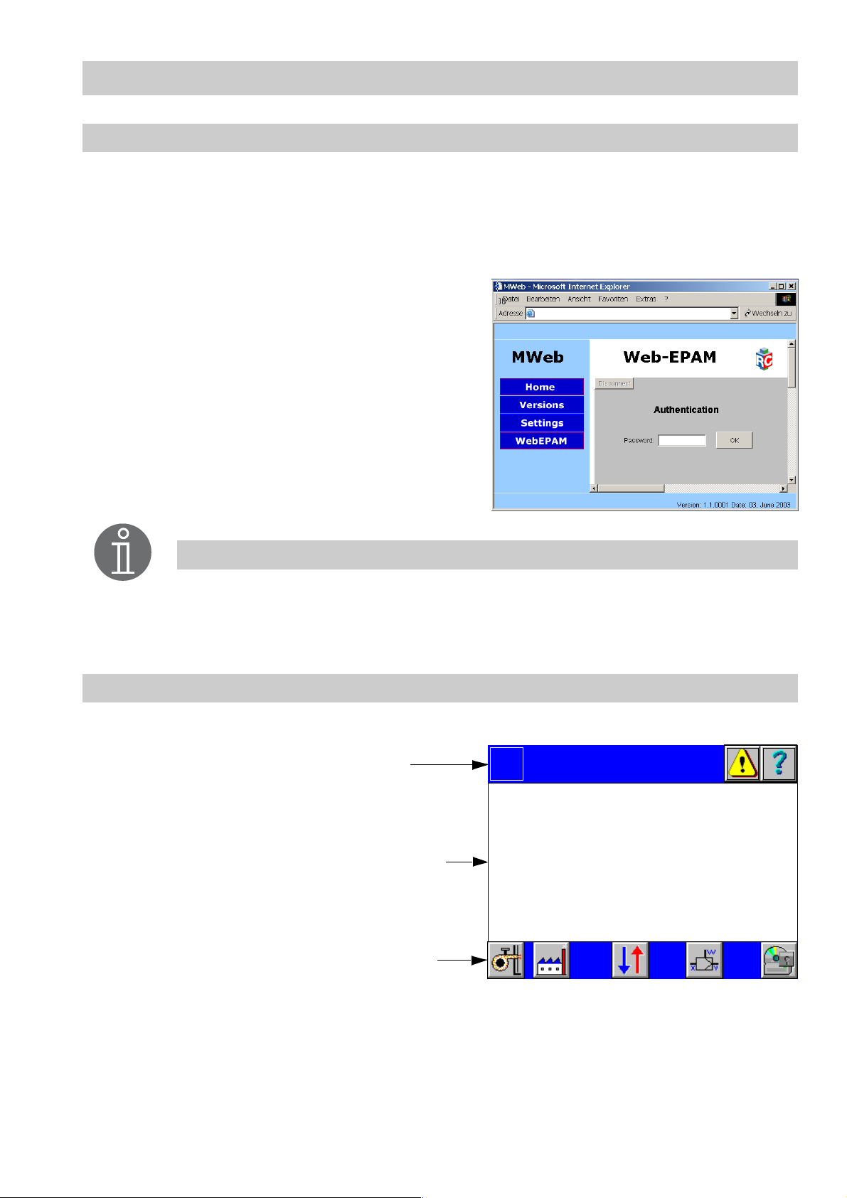
Description of the browser interface
SPECTOR
control
can be operated remotely via Internet Browser.
For the remote access via Intranet a valid IP address is required.
For more information on how to establish an IP address see chapter System, menu
IP addresses. T o call up the page enter http://IP address.
The buttons on the left side of the screen can be
used to show current configuration settings.
http://194.31.73.150
To show th e user int erface o f SPECTORcontrol
press button WebEPAM and enter your
password.
To confirm your input press button OK .
Note
For security reasons only one logged-in user can access the system via
browser. The direct operation of SPECTORcontrol is still pos sible, but a
simultaneous operation (local and remote acces s) should be avoided.
Description of the user interface
The user interface consists of three areas:
Title bar
Logo
Overview
00.00.00 00:00:00
Display field
Symbol bar
The title bar shows the c ompany logo, the title of the menu and two buttons.
All other menus have three buttons.
The display field changes its appearance accor d ing to the indicated menu.
The symbol bar shows the available functions of the indicated menu.
15
Page 16
User Interfaces – continued –
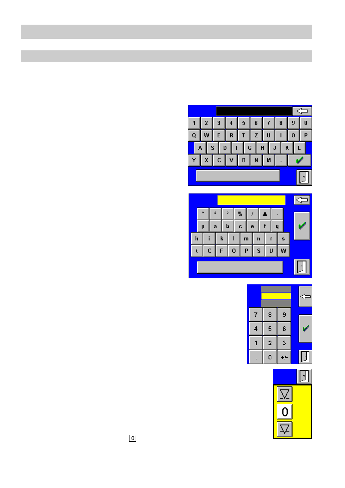
Description of the input masks
The input masks are designed for entering values without a keyboard.
Data is entered directly via touch screen panel and remote input is effected by clicking on
the respective icons of the user interface screen masks with a mouse.
For the input mask only the indicated (limited)
set of characters can be used.
Only upper case letters are indicated and used
(cas e insensitivity).
A plausibility test is not carr ied out.
The input mask is for entering units and
dime nsions.
Note that when changing the l anguage,
country-specific units (e. g. temperature) will
not be changed!
A plausibility test is not carr ied out.
Input:
Cur:
For the input mask only the indicated (limited)
set of characters can be used.
Min. and max. values are indicated above and
below the current entry.
Values that are not within the admissible range
of values will not be accepted .
The mask is used for selecting the type of
manual operation.
In the 3 button menu the controller motors
cont inuously to the selected end position. The
changing value of the manipulated variable is
optically indicated in the previous menu and
the selected mode of operation is shown by the
icon of the button. Press button to interrupt
or terminate the process.
Min.:
Cur.:
Max.:
Manual
Operation
Open
Stop
Close
16
Page 17
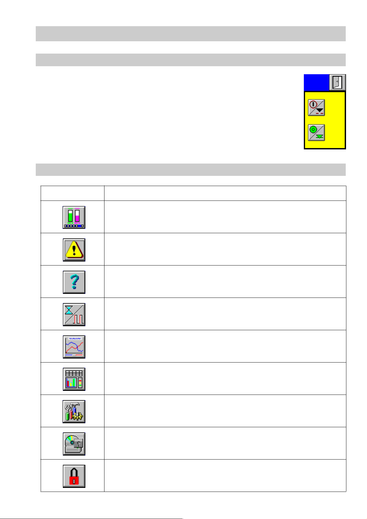
User Interfaces – continued –
Description of the input masks - continued -
The mask is used for selecting the type of
manual operation.
In the 2 button menu the controller motors
continuously to the selected end position. The
attained mode of operation is optically
indicated in the previous menu. T he selected
mode of operation is indicated by the icon on
the button.
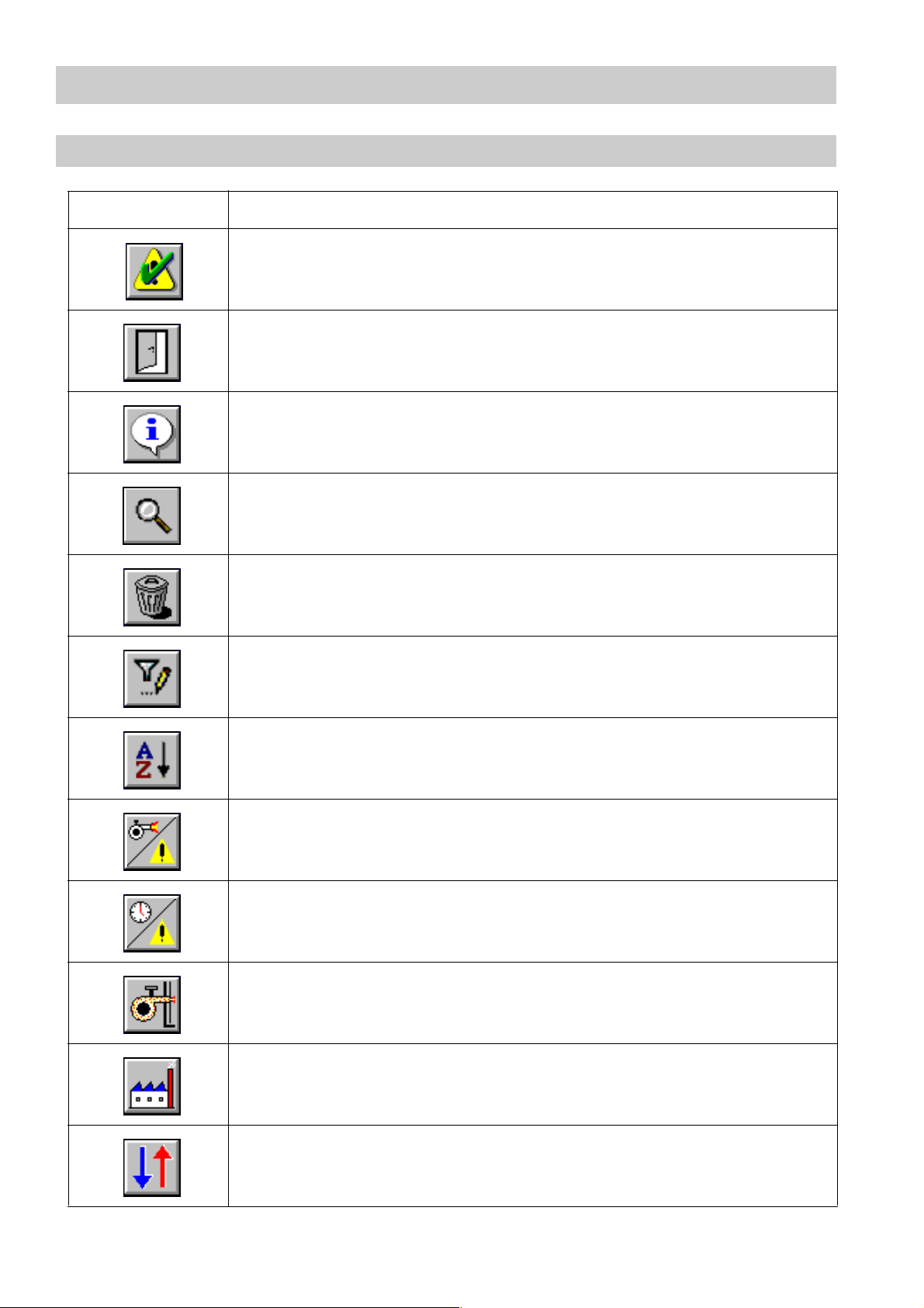
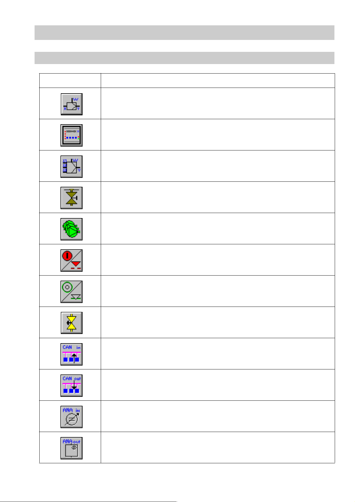
Description of buttons
Button Description
Return to start menu
grey = no alarm activated
Current alarm indication red = alarm acknowledged but still activated
flashing = alarm activated and not acknowledged
Manual
Operation
Open
Close
Indicate he lp text s fo r cu rr en t pa ge
Indicate maintenance
Indicate datalogs
Indicate quantities
Indicate configuration
Indicate system settings
Indicate password entry
17
Page 18
User Interfaces – continued –
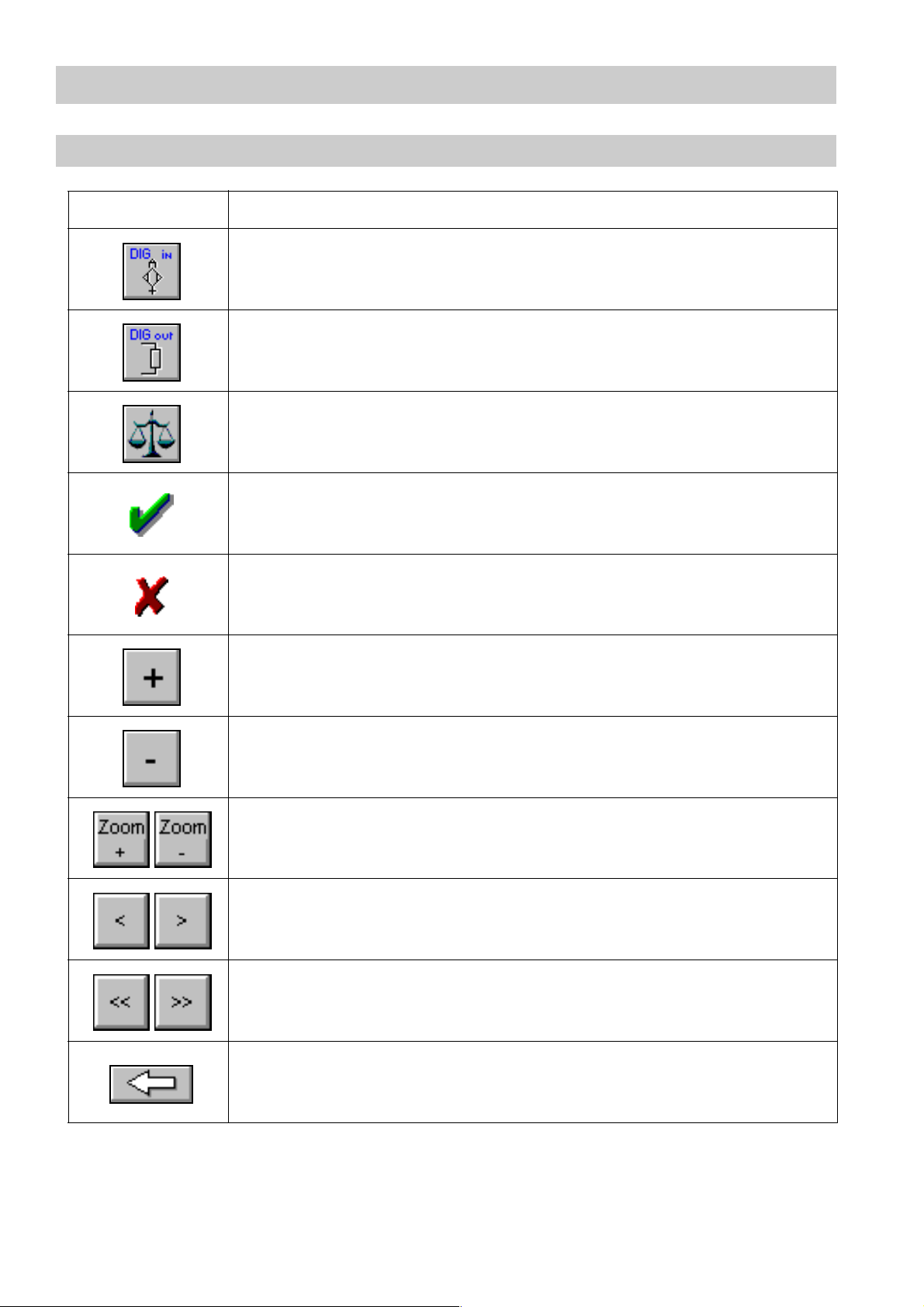
Description of buttons - continue d -
Button D escription
Acknowledge alarm
Quit
current menu
Go to source (origin) of malfunction message
Indicate alarm details
Delete all history messages (waste bin)
Indicate filters of alarm history
Indicate sorting of alarm hi sto ry
Indicate malfunction history of the burner
Indicate fault history of th e bu rn e r
Indicate burner menu
18
Indicate boiler menu
Indicate I/O menus
Page 19
User Interfaces – cont inued –
Description of buttons - continued -
Button Description
Indicate controller menu
Indicate values of c ontrol equipment
Indicate 3-element control menu
Indicate intermittent boiler blowdown
Indicate multiple pump control
Valve position co ntrol OPEN/pump ON
Valve position co ntrol CLOSED/pump OFF
Indicate valve control or single pump control
Indicate CAN inputs
Indicate CAN outputs
Indicate analog inputs (I/O modu le)
Indicate analog outputs (I/O module)
19
Page 20
User Interfaces – cont inued –
Description of buttons - continue d -
Button D escription
Indicate digital inp uts (I/O module)
Indicate digital outputs (I/O module)
Indicate calibration
Acknowledge / accept
Delete
Plus (time)
Minus (time)
Zoom plus/ minus (in datalog)
Forwards/backwards in steps of 3 min. (in datalog)
Forwards/backwards in steps of 10 min (i n datalog)
20
Backspace
Page 21
User Interfaces – cont inued –
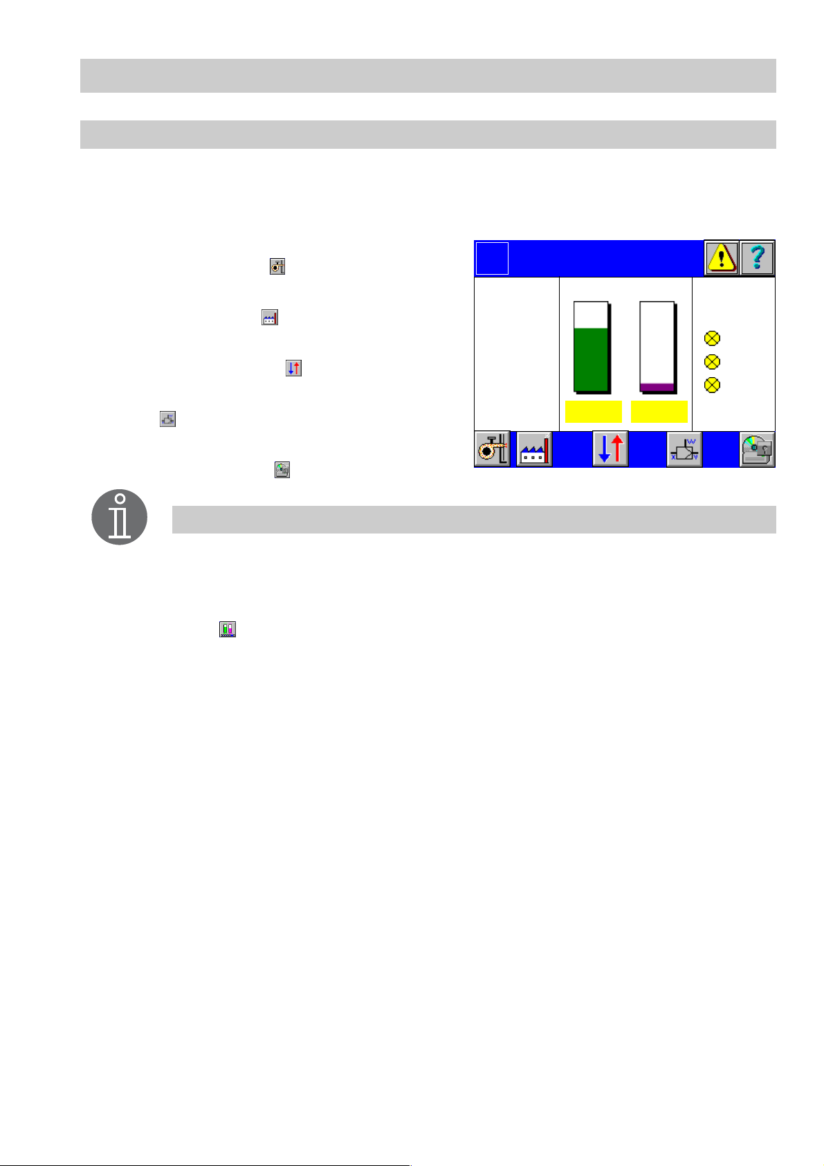
Menu o vervi ew
The display field shows all important current parameters of the boiler, e. g. level (CAN
input 1) and conductivity (CAN input 2) as well as specific burner data. The display is
made to the customer's specification and therefore serves here only as an example.
■ To show the configuration or current values
of the burner, press .
■ To show the configuration or current values
of the boiler, press .
■ To show the values or configuration of
inputs/ outputs, press .
■ To show or configure values of the controller,
press .
■ To show the configuration or current values
of the system, press .
Note
CAN input 1 is linked wi th level indication and CAN input 2 with conductivity
indication in the menu Overview. The values of equipment configured for
these inputs are shown in the menu Overview.
Use , which is not shown in this menu, to jump from all submenus directly
to the menu Overview. If no inputs are made within a certain period of time,
the system automatically returns to the overview menu.
Logo
Burner
P 20.0%
Actual 87.0 °C
Setp. 88.0 °C
O² - 0.1%
Overview
Level
Conductivity
492.9 µs71%
Boiler
LW 1
LW 2
HW
21
Page 22

System Menu
Sequence of set-up
Before starting the set-up procedure, make sure that all devices are interconnected via
CAN bus . The CANopen protocol is used for the data exchange between the equipment
groups.
To be able to access the CANopen equipment of the plant you must first check and, if
necessary, modify the basic settings.
Pre-configured installa tions will be completely parameterized by GESTRA. The data are
stored on the CompactFlash™ card. Modifications are therefore not necessary.
For a subsequent installation or expansion of SPECTORcontrol follow the configuration
step s described below.
Note
Any modification of t he basic settings has a direct effect on the boiler
monitoring system and the operating functions .
We recommend the following configuration sequence:
1. Check/configure system settings
2. Check/configure connected CANopen equipment
3. Check/configure connected analog equipment (I/O module)
4. Check/configure connected digital equipment (I/O modul e)
5. Check/configure connected controller
6. Check/configure boiler parameter settings
7. Check/configure burner parameter settings
8. After finishing the configuration restart the system.
(Only applicable if settings of CANopen equipment - cf. item 2 - were modified)
Note
SPECTORcontrol does not have an own on/off switch. To turn the equipment
on/off, switch on/off the power supply in the control cabinet or connect/strip
off the plug-in connection of the equipment.
22
Page 23
System Menu – continued –
System
To configure the system press button in the menu O verview.
■ To set the time, press button Set time.
■ To change the contrast and the brightness of
the screen, press button Change contrast.
■ To change the language, press button
Language.
■ To change the password, press button
Change password.
■ To change the IP address, press button
Change IP.
■ To save or restore the default plant configu-
ration, press button Factory settings.
Note
All changes of the configuration take an immediate effect. However, changes
of the IP address and/or the node ID will only become effective after a restart.
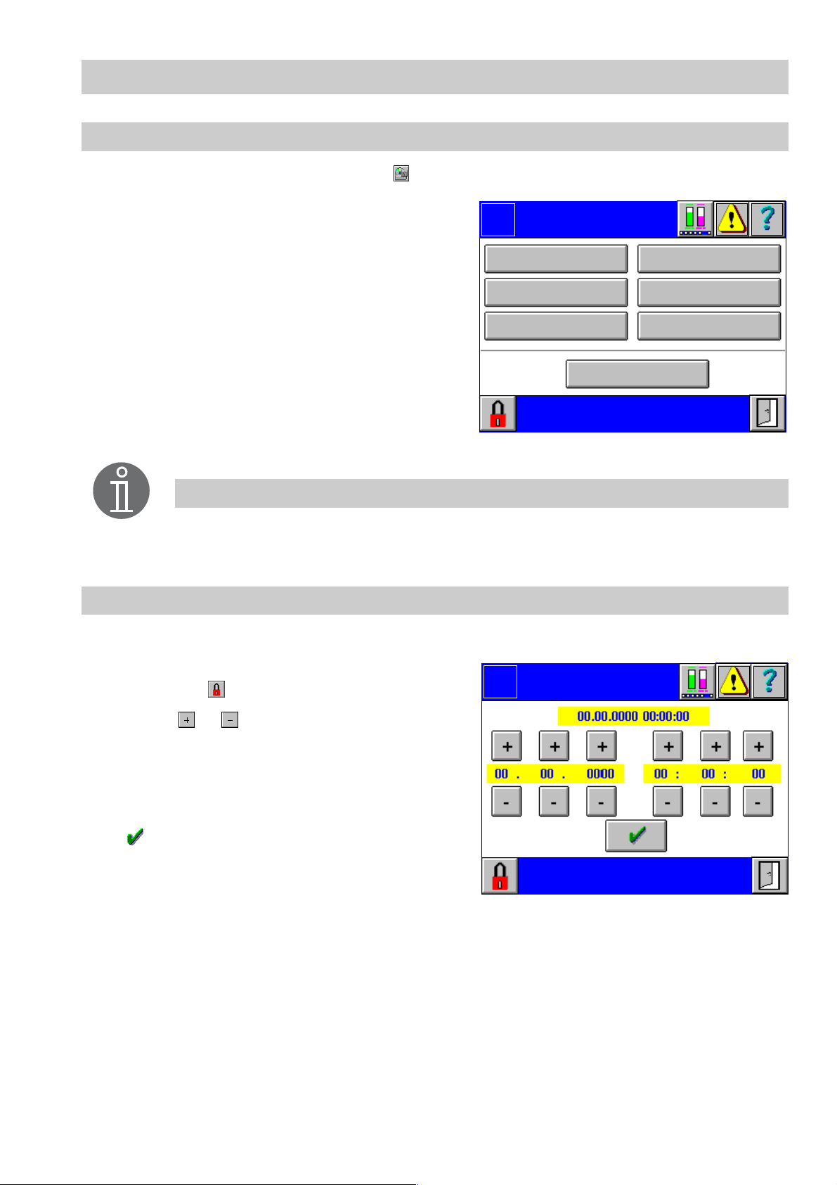
Date and time setting
Logo
Change contrast
Set time
Language
System
Change password
Change IP
Factory settings
Canalyzer
1. To set the t ime, click button Set time in the menu System.
2. The date/tim e setting is password protect-
Logo
ed. Press and enter your password.
3. Press or above and below the date
and time settings to change the indicated
values. The values are changed incrementally.
4. To accept the date and time settings press
.
Date
Time
23
Page 24
System Menu – continued –
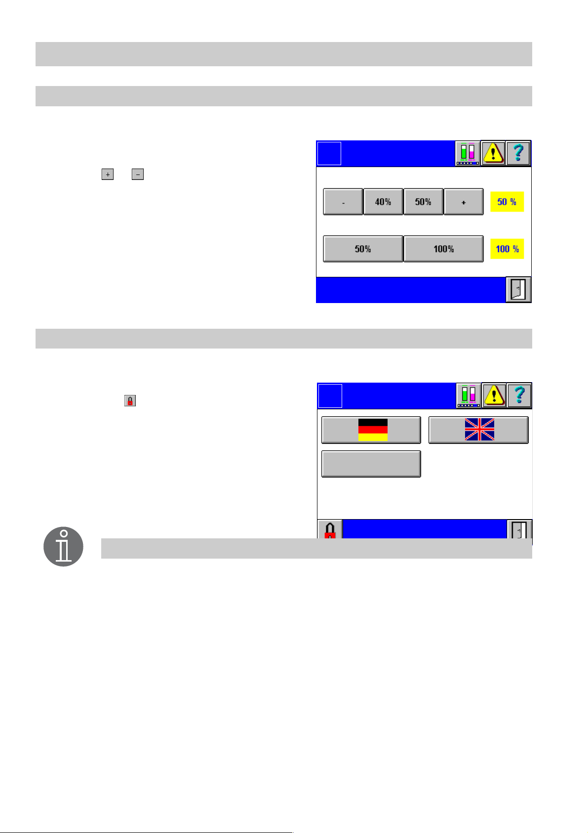
Contrast and backlight setting
1. Press button Change contrast in the menu System.
2. To change th e contrast (difference between light and dark areas of the screen),
press or to the left an d right sides of
the fixed values of 40 % and 50 %. The
current value takes immediate effect and
is highlighted in yellow.
3. The backlight (brightness of the screen
display) can be set to 50 % or 100 % by
pressing the respective button.
The selected value takes immediate effect
and is highlighted in yellow.
Language
1. Press button Language in the menu System.
2. The language setting is password protected. Press and enter your password.
3. To change the language press the button
with the country flag in question. The selected language takes immediate effec t
and is shown in the menu bar.
Logo
Contrast
Backlight
Logo
Contrast
Backlight
Language
24
Note
Additional languages can be use d.
Page 25
System Menu – continued –
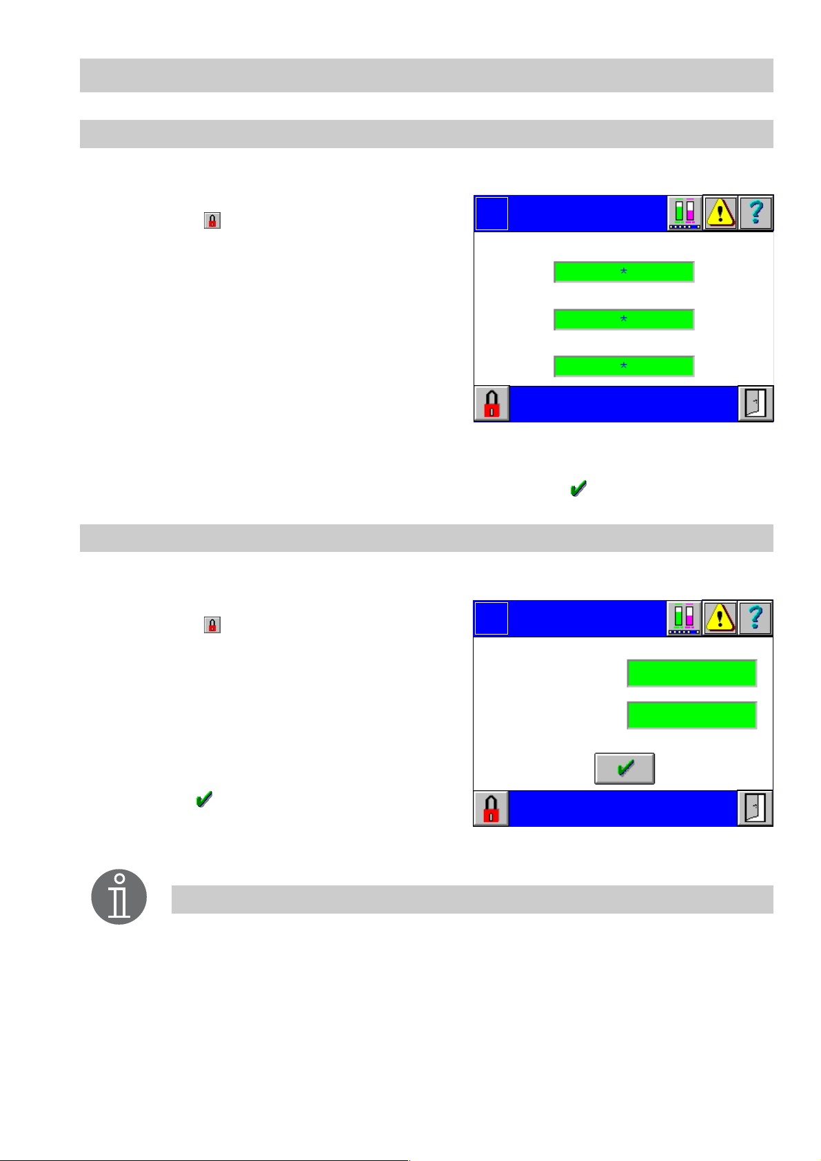
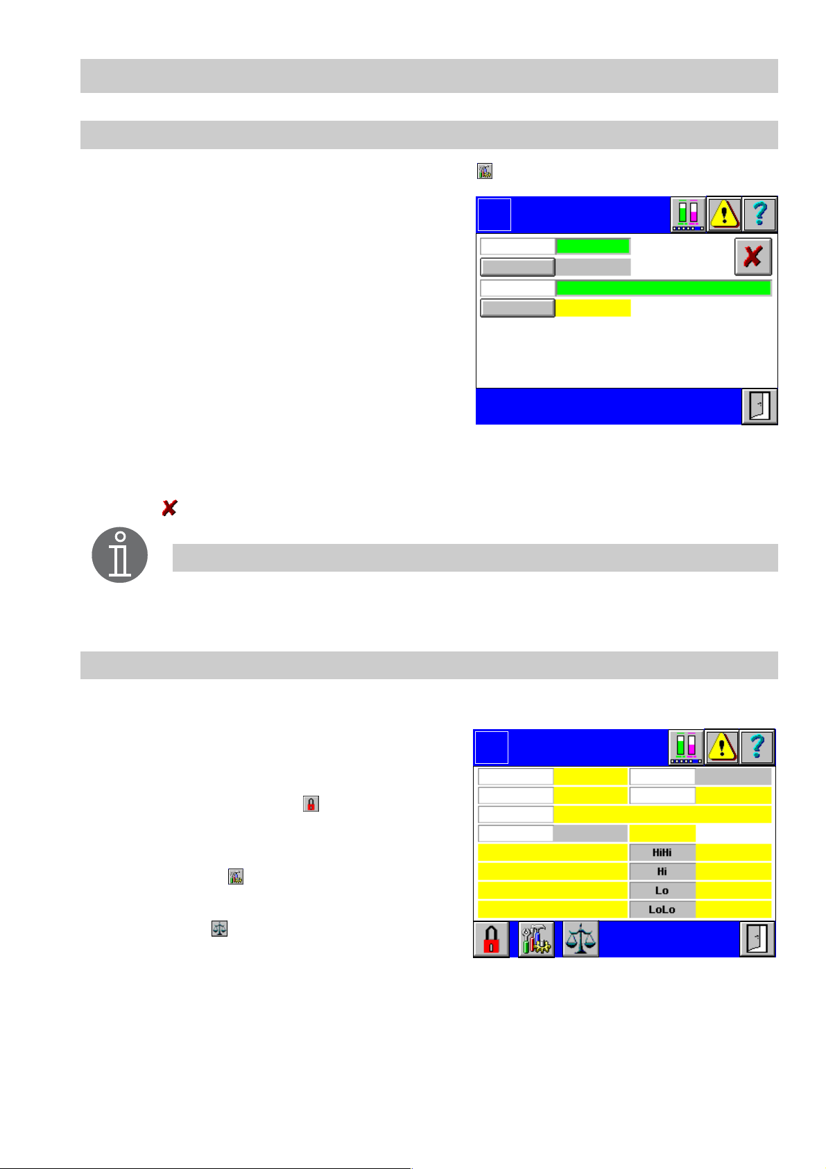
Passwor d
1. Press button Change password in the menu System.
2. The menu Password is password protected. Press and enter your password.
Logo
Password
3. According to the level of authorization one
or more green inpu t fields are shown. An
Level 1:
asterisk appears fo r each character you
enter.
4. Click in the input field that you want to
change .
Level 2:
Commissioning
Level 3:
5. The current value appears as plain text in
the inp u t mask. Use the on-screen keyboard to overwrite or modify the value.
Note that at most 8 characters can be enter ed.
6. Confirm the input of the password by pressing the button .
IP add ress se ttin gs
1. Press button Change IP in the menu System.
Operator
Engineer
2. The menu Change I P is password protect-
ed. Press and enter your password.
3. Click in the input field that you want to
change .
4. The current value appears in the input
mask. Use the on-screen keyboard to
overwrite or modify the value.
5. Confirm the input of all IP addresses by
pressing .
6. After finishing the configuration restart the
system.
Note
All changes of the configuration take an immediate effect. However, changes
of the IP address and/or the node ID will only become effective after a restart.
Logo
IP address Target:
IP address Gateway:
IP address
25
Page 26
System Menu – continued –
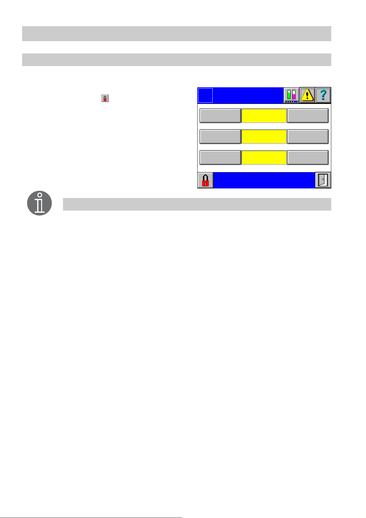
Fa ctory se ttin gs
1. Press button Factory settings in the menu System.
2. The menu Factory settings is password
protected. Press and enter your password.
3. According to the level of authorization one
or more yellow input fields with the "Saved
on" date are shown.
4. Click on the button of the settings that you
want to save or load.
Note
The accumulated maintenance and quantity data will not be over written. All
adjusted parameters remain stored.
Logo
Save
Save
Save Load
Factory
settings
Setting s 3
00.00.0000 00:00
Settings 2
00.00.0000 00:00
Settings 1
00.00.0000 00:00
Load
Load
26
Page 27
Menus of Inputs/Outputs
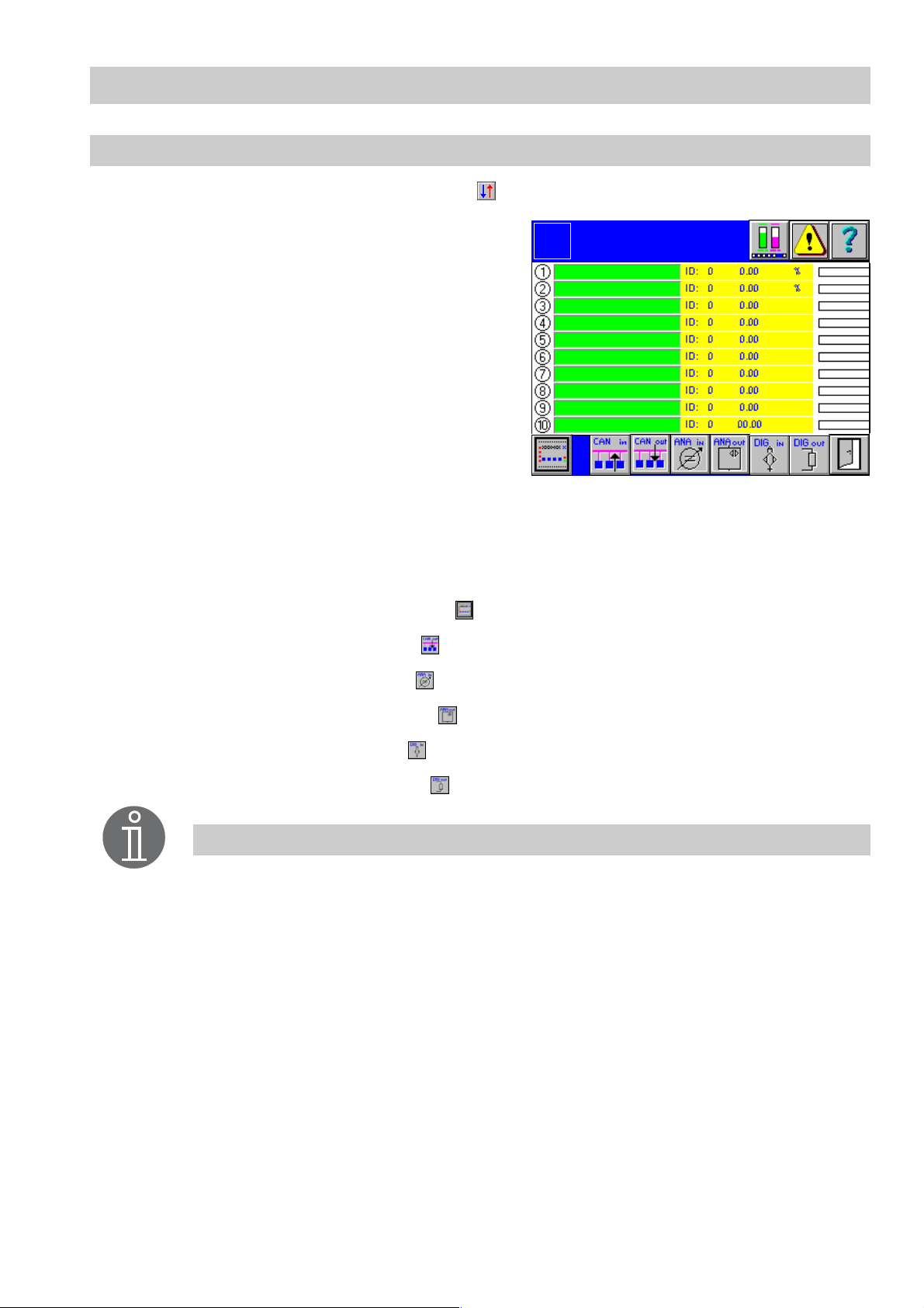
CAN 1..10 input
To adjust the inputs / outputs press button in the menu Overview.
1. The green input fields list the names of the
current CAN inputs. Active inputs are indi-
Logo
CAN 1 ..10
Input
cated by the illumina ted yellow number on
the left side. A node I D conflict is indicated
by a mark at the left side of the ID setting.
At the right side the currently measured value, the as sociated unit and the graphical
representation is sh own. Current alarms
are indicated for each individual input by a
mark at the left side of the graphical representation.
2. To re-configure an input click in the green input field. The menu CAN Typ e 1...10
pops up.
If one input has already been configured its designation will appear in the input field.
Click in the input field to call up the corresponding menu directly.
■ To show the control equipment press .
■ To call up the CAN outputs press .
■ To show the analog inputs press .
■ To call up the analog outputs press .
■ To show the digital inputs press .
■ To call up the digital outputs press .
Note
CAN input 1 is linked with leve l indication and CAN input 2 with co nductivity
indication in the menu Overview.
The values of these devices are currently indicated in the menu Overview.
27
Page 28

Me nus o f In pu ts/O utp uts – conti nue d –
CAN type 1..10
1. Click in the menu CAN 1..10 Input in the new input field that you want to configure.
2. Select the device to be configured.
CAN type 1..10
3. To delete an entry press .
NRG 26-40
NRG 16-42
LRG 16-40
Note
All devices that can be used with SPECTORcontrol are indicated in the
equipme nt list.
NRG 26-40 CAN 1...10
1. Click in the menu CAN 1..10 Input in the green input field of the device in question.
2. The display field shows the current values
of the equi pment.
Logo
NRG 26-4 0
CAN 1
3. The menu NRG 26-40 CAN 1..10 is password protected. Press and enter your
password.
4. To show the setup menu press .
5. To access the menu NRG 26-40 Calibra-
tion press .
Reading
Name
0
0%
0 %
0 %
0 %
0 %
Node
Electrode online
Temp.in terminal box OK
OffNode ID
28
Page 29

Me nus o f In pu ts/O utp uts – conti nue d –
NRG 26- 40 setu p
1. In the menu NRG 26-40 CAN 1...10 press .
2. To establish or change the node ID click in
the green input field.
3. Use the on-screen keyboard to overwrite
or modify the value in the input mask.
4. Use button Node On/Off to activate or deactivate the node ID.
5. To name the NRG 26-40 click in the input
Logo
Node ID
Node On
Name
NRG 26-40
Setup
0
Node Off
0 %
0 %
0 %
0 %
Delete
electrode?
field Name.
6. Use the on-screen keyboard to overwrite
or modify the value in the input mask.
7. To change the values of the NRG 26-40 click in the i nput field.
8. Use the on-screen keyboard to overwrite or modify the value in the input mask.
9. Use to delete the adj usted equipment or to change the type of CAN electrode.
Note
The HiHi and LoLo settings can be used for alarms and the Hi and Lo settings
for switchpoints of 2-position controllers.
The alarm monitoring function is de-activated when all HiHi to LoLo values
have been set to 0%.
The node ID settings of SPECTORcontrol must agree with the settings of the
respective devices.
29
Page 30

Me nus o f In pu ts/O utp uts – conti nue d –
NRG 26-40 calibration
1. In the menu NRG 26-40 CAN 1...10 press .
2. Choose a reference point at the boiler
(e. g. bottom edge of sightglass), fill the
boiler up to this point and then press button 0% Calibration to acknowledge.
3. After calibrating the zero point, 100% must
Logo
Level
NRG 26-4 0
Calibration
100 %
0
Cali. value
be calibrated. F o r this purpose click in the
green input fi eld.
4. Use the on-screen keyboard to overwrite
0%
0% Calibratio n
or modify the value in the input mask.
5. Choose a value between >50% ( e . g. m i d dle of sightglass) and <100% ( e. g. top
edge of s ightglass).
Fill the boiler until the set marking is reached an d press button 100% Calibration to
acknowledge.
NRG 16-42 CAN 1...10
1. Click in the menu CAN 1..10 Input in the green input field of the device in question.
2. The display field shows the current values
of the equi pment.
3. The menu NRG 16-42 CAN 1..10 is password protected. Press and e nter your
password.
4. To show the setup menu click button .
Logo
Reading
Name
NRG 16-42
CAN 1...10
0
0 %
Node
Electrode online
Temp. interminalboxOK
OffNode ID
0.5 µSSense
30
Page 31
Me nus o f In pu ts/O utp uts – conti nue d –
NRG 16- 42 setu p
1. In the menu NRG 16-42 CAN 1...10 press .
2. To establish or change the node ID
click in the green input field.
3. Use the on-screen keyboard to overwrite
or modify the value in the input mask.
4. Use button Node On/Off to activate or de-
Logo
Node ID
Node On
Name
S e ns e 10 µS
NRG 16-42
Setup
0
Node Off
0.5 µ S
Delete
electrode?
activate the node ID.
5. To name the NRG 16-42 click in the input
field Name.
6. Use the on-screen keyboard to overwrite
or modify the value in the input mask.
7. Use button Sen se 10/ 0.5 µS to toggle between the two values. The adjusted value
is highlighted in yel low.
8. Use to delete the adj usted equipment or to change the type of equipment.
Note
The node ID s ettings of SPECTORcontrol must agree with the settings of the
respective devices.
LRG 16 -40 CAN 1...10
1. Click in the menu CAN 1..10 Input in the green input fi eld of the device in question
2. The display field shows the current values
of the equi pment.
3. The menu LRG 16-40 CAN 1..10 is password protected. Press and enter your
password.
4. To show the menu LRG 16-40 Set up
press button .
5. To access the menu LR G 16-40 Calibra-
Logo
Node ID
Readin g
Name
Ele ct r od e on lin e
Tem p. in ter m inal box OK
PT1000 OK
LRG 16-40
CAN 1
0
0.0 µ S
OffCompens.
Temperature
1234567890
Node
Off
0 °C
0 µS
0 µS
0 µS
0 µSElect rode OK
tion press .
31
Page 32

Me nus o f In pu ts/O utp uts – conti nue d –
LRG 16-40 setup
1. In the menu LRG 16-40 CAN 1...10 press .
2. To establish or c hange the node ID
click in th e green input field.
3. Use the on-screen keyboard to overwrite
or modify the value in the input mask.
4. Use button Node On/ Of f to activate or deactivate the node ID .
5. To name the LRG 16-40 click in the input
Logo
Node ID
Node On
Name
Range 100%
Range 0%
LRG 16-40
Setup
0
Node Off
0.00
0.00
Delete
electrode?
0 µS
0 µS
0 µS
0 µS
field Name.
6. Use the on-screen keyboard to overwrite
or modify the value in the input mask.
7. To change th e values of the LRG 16-40 click in the input field. First establish the
0% -100% range and then enter further values.
8. Use the on-screen keyboard to overwrite or modify the value in the input mask .
9. Use to delete the adjusted equipment or to change the type of equipment.
Note
The HiHi and LoLo settings can be used for alarms and the Hi and Lo settings
for switchpoints of 2-position controllers.
For the 72 hrs operation according to TRD 604 the switchpoint HiHi does not
replace t he independent equipme n t in the safety chain
The alarm monitoring function is de-activated when all HiHi to LoLo values
have been set to 0 µS.
The node ID settings of SPECTORcontrol must agree with the settings of the
respective devices.
32
Page 33

Me nus o f In pu ts/O utp uts – conti nue d –
LRG 16 -40 ca libra tion
1. In the menu L RG 16-40 C AN 1 .. .10 pres s .
2. Use button Compensation On/Off to activate or de-activate the temperature compensation. All indicated readings are here
Logo
Compensation Off
LRG 16-40
Calibration
Autoscan
Auto activ.
absolute readings of the current conductivity.
3. To carry out an autoscan press button Au-
Standard curve
Linear
toscan. The auto-curve temperature com-
pensat ion is suitable for boilers operating
Cell constant
0.000
with variable pressure, which means that
the boiler does not have a fixed working
pressure (e. g. low l oad 10 bar, full load 15
bar). The system detects in steps of 10 °C
all temperature and conductivity values from 100 °C to the service temperature. For
this purpose the boiler must reach its working pressure (with variable pressure operation: ma x. allowable working pressure). If the standard curve is not suitable for variable pressure operation, use can be made of the recorded curve.
4. If you want to use the autoscan values, e. g. because the standard curve is not suitable, press button Auto activ.. The previously recorded auto-curve will be activated.
The auto-curve can be overwritten by a newly recorded curve at any time.
5. To adjust the standard-curve temperature compensation click in the green input field.
Th e menu Select standard curve appears. The standard curve temperature compensat ion is suitable for boilers o perating with variable pressure, which means that
the boiler d oes not have a fixed working pressure (e. g. low load 10 bar, full load 15
bar). The standard c urves of feedwater condi tioning agents with different basic conductivities compensate for the influence of the temperature on readings within the operating range.
6. To adjust the linear temperature compensation click in the input field next to the button Linear. The menu Select temperatur e coefficient appears. The gradient (de-
fault setting: 2.1%/°C) is normally used for steam boilers operating with constant
pressure. The con ductivity is ascertained a t an ambient temperature of 25 °C. The
cell constant can be modified in order to calib rate the value measured by the electrode. The gradient can be verified at operating pressure with the aid of a calibrated
conductivity meter .
7. Click in the green input field to enter the cell constant C of the conductivity electrode
(values must be within the admissible range).
8. Use the on-screen keyboard to overwrite or modify the value in the input mask.
33
Page 34

Me nus o f In pu ts/O utp uts – conti nue d –
LRG 16-40 calibration - conti nued -
Note
With increasing press u re and temperature the conductivity i s no longer a
linear function. Choose a suitable temperature compensa tion method.
Sele ct sta ndard cu rve
1. Click in the green input field of the menu LRG 16-40 Calibration
2. Select in the menu Select standa rd curve the
corresponding standard temperature curve. The
curves are applicable for various feedwater condi-
Select standard curve
NaHO+H2O 260µS
tioning agents with different basic conductivities.
For more information refer to the installation manual of the equipment.
NaHO+H2O 1080µS
NaHO+H2O 5400µS
NaHO+H2O 11200µS
Na3PO4+H2O 190µS
Na3PO4+H2O 1100µS
Select temperature coefficient
1. Click in the green input field of the menu LRG 16-40 Calibration
2. Select in the menu Select temperature coef-
ficient the corresponding gradient.
Selec t temp. coefficie nt
0
34
1.6 % / °C
1.7 % / °C
....
2.9 % / °C
3.0 % / °C
Page 35

Me nus o f In pu ts/O utp uts – conti nue d –
Current v alues of control equipment
To adjust the control equipment press button in the menu CAN 1..10 Input.
1. The display f ield shows the current name
and node ID of the control equipment. Active equipment is indicated by a signal at
the left side. If there is a malfunction the
buttons or the text boxes are highlighted in
red.
2. To show the configuration of the control
equipment press the respective button.
Note
All devices that can be used with SPECTORcontrol are indicated in the
equipme nt list.
NRS 1- 40
Logo
Current values
Control Equipment
NRS 1-40
NRG 16-40
NRG 16-40
NRS 1-41
NRS 1-41
LR R 1- 40
Name
ID
0
0
0
0
0
0
To adjust the control equipment pr ess button NRS 1-40 in the menu Current values of
control equipment.
1. The display field shows the current parameters of the control equipment. Malfunctions ar e indicated in red.
2. The menu NRS 1-40 is password protected. Press and enter your password.
3. To show the setup menu press button .
Logo
Name
Node
Control equipment online
Relay (de)energ. OK
Relay A OK Relay D OK
El ectrod e 1 Online
Ele ctrod e 1 OK
Electr. 1 term. temp. OK
NRS 1-40
Low le vel lim iter
Off
Relay C OK
Node ID
NRS 1-40 OK
El ectrod e 2 Online
Ele ctrod e 2 OK
Electr. 2 term. temp. OK
0
35
Page 36

Me nus o f In pu ts/O utp uts – conti nue d –
NRS 1-41
To adjust the control equipment press button NRS 1-41 of the menu Current values of
control equipment.
1. The display field shows the current parameters of the c o ntrol equipment. Malfunctions are indicated in red.
2. The menu NRS 1-41 is password protected. Press and enter your password.
3. To show the setup menu press button .
NRS 1-40/ 41 setup
1. In the menu NRS 1-40 or NRS 1 -41 press .
2. To establish or c hange the node ID
click in th e green input field.
3. Use the on-screen keyboard to overwrite
or modify the value in the input mask.
4. Use button Node On/ Of f to activate or deactivate the node ID .
Logo
Name
Node
Contr ol equipment online
Relay (de)energ. OK
Relay A OK
Relay C OK
Relay D OK
Logo
Node ID
Node On
Name
NRS 1-41
NRS 1-40
Setup
0
Node Off
Low level limiter
Off
Node ID
Electrode online
Electrode OK
Electrode term. temp. OK
NRS 1-41 OK
0
5. To name the control equipment click in the
input field Name.
6. Use the on-screen keyboard to overwrite
or modify the value in the input mask.
Note
The node ID settings of SPECTORcontrol must agree with the settings of the
respective devices.
36
Page 37

Me nus o f In pu ts/O utp uts – conti nue d –
LRR 1-40
1. Press button LRR 1-40 in the menu Current values of control equipment.
2. The display field shows the current values
of the equi pment.
3. The menu LRR 1-40 Setup is password
protected. Press and enter your password.
4. To show the setup menu click button .
LRR 1-40 setup
1. In the menu LRR 1-40 press .
2. To establish or change the node ID
click in the green input field.
3. Use the on-screen keyboard to overwrite
or modify the value in the input mask.
4. Use button Node On/Off to activate or deactivate the node ID.
Logo
Name
Node
Node ID
Max. lim it
Control equipment online
Logo
Node ID
Node On
Name
Write
max. li mit
LRR 1-40
LRR 1-40
Node Off
Conductivity
Off
0
0
Setup
0
0
5. To name the LRR 1-40 click in the input
Read
max. limit
0
field Name.
6. Use the on-screen keyboard to overwrite
or modify the value in the input mask.
7. The current limit value is highlighted in yellow. To change the max. limit click in the
corresponding input fi eld.
8. Use the on-screen keyboard to overwrite or modify the value in the input mask.
9. When the entered limit value is accepted, it will be sent to the equipment. The value
is immediately active and displayed in the menu.
Note
The node ID s ettings of SPEC TORcontrol must agree with the settings of the
respective devices.
37
Page 38

Me nus o f In pu ts/O utp uts – conti nue d –
CAN 1..10 output
1. In the menu Inputs or Outputs press .
Digital inputs
1. In the menu Inputs or Outputs press .
2. The display field shows the c onnected
signals. Active connections are indi cated
by a yellow signal at the left side.
3. The menu Digital Inputs is password protected. Press and enter your password.
4. To designate a signal click in the green input field.
5. Use the on-screen keyboard to overwrite
or modify the value in the input mask.
6. The Alarm buttons feature three different
indicating functi ons:
Alarm with signal value 0 (O FF) (yellow)
Alarm with signal value 1 (O N) (yellow)
Alarm OFF (grey)
7. To go to the CAN input press .
8. To go to the CAN output press .
9. To go to the analog input press .
Logo
Sig. 1
Sig. 2
Sig. 3
Sig. 4
Sig. 5
Designation
Designation
Digital
Inputs
Alarm
with 0
Alarm
with 1
Alarm
Off
Alarm
Off
Alarm
Off
10. To go to the analog output press .
11. To go to the digital output press .
38
Page 39

Me nus o f In pu ts/O utp uts – conti nue d –
Digital outputs
1. In the menu Inputs or Outputs press .
2. The display f ield shows the connected
signals. Active outputs are indicated by a
yellow signal at the left side.
3. The menu Digital Outputs is password
protected. Press and enter your pass-
Logo
Sig. 1 Designation
Sig. 2
Sig. 3
Digital
Outputs
Alarm
Alarm
Alarm
word.
Sig. 4
Alarm
4. To designate a sig nal click in the green input field.
Sig. 5
Alarm
5. Use the on-screen keyboard to overwrite
or modify the value in the input mask.
6. To show the status of a signal press button Signal 1...10 at the left side. A new menu
will pop up.
7. Press button Alarm to link the digital output with an alarm (HiHi/LoLo) of the CAN
inputs or with analog inputs.
8. Select the signal that indicates the required parameters. For more information on the
setup and configuration of the equipment see chapters CAN Input and Analog Input.
After selecting an input establish the alarm limit HiHi or LoLo. W hen the alarm is
raised t he digital output will be switched off.
9. To go to the CAN input press .
10. To go to the CAN output press .
11. To go to the analog input press .
12. To go to the analog output press .
13. To go to the digital input press .
39
Page 40

Me nus o f In pu ts/O utp uts – conti nue d –
Digital output 1...10 energised
1. Press button Signal 1...10 in the menu Digit al Outputs.
2. The display field shows the parameters of
the digital output.
3. The menu Digital Outputs is password
protected. Press and enter your password.
Logo
Signal from
Type
Signal
DO 1
energised
2-position controller
Controller 2
Open
40
Page 41

Me nus o f In pu ts/O utp uts – conti nue d –
Analog 1..10 input
1. In the menu Inputs or Outputs press .
2. The green input fields list the names of the
current analog inputs. Active inputs are indicated by the illuminated yellow number
on the left side. At the right side the currently measured value, the associated unit and
the graphical representation are shown.
Current al arms are indicated for each individual input by a mark at the left side of the
graphica l representation .
3. To configure an input click in the green input field. The menu Analog Input 1...10
pops up.
■ To show the CAN inputs press .
■ To call up CAN outputs press .
■ To call up the analo g outputs press .
■ To show the digital inputs press .
Logo
Analog 1..10
Input
■ To call up the digital outputs press .
Analog input 1..10
1. Click in the menu Analog 1..10 Input in the green input field.
2. The display field shows the par ameters of
the anal og input.
3. To configure the analog inputs press .
Logo
Type
AI Status
Name
Reading 0.00
Range 100%
Range 0%
Analog
Input 1
PT100
Off
0.00
0.00
PT 100
OK
0.00
0.00
0.00
0.00
41
Page 42

Me nus o f In pu ts/O utp uts – conti nue d –
Analog input 1...10 setup
1. In the menu Analog Input 1...10 press .
2. The menu Analog Input 1...10 Setup is
password protected. Press a nd enter
your password.
3. To select the type of sensor press button
Logo
Type
AI On
Name
AI 1
Setup
PT100
Off
Unit
PT 100
Type. The available types of sensor are
shown in a list.
4. To activate or de-activate the analog input
press but ton A I On/Off.
Range 100%
Range 0%
0.00
0.00
0.00
0.00
0.00
0.00
5. To select the unit of the measured value
click in th e green input field.
6. Use the on-screen keyboard to overwrite or modify the unit in the input mask.
7. To name the analog input click in the input field Name.
8. Use the on-screen keyboard to overwrite or modify the value in the input mask .
9. To change the range limits click in the corresponding input field. First establish the
0% -100% range and then enter further values.
10. Use the on-screen keyboard to overwrite or modify the val ue in the input mask.
Note
The HiHi and LoLo settings can be used for alarms and the Hi and Lo settings
for switchpoints of 2-position controllers.
The alarm monitoring function is de-activated when all HiHi to LoLo values
have been set to 0%.
42
Page 43

Me nus o f In pu ts/O utp uts – conti nue d –
Analog 1..10 output
1. In the menu Inputs or Outputs press .
2. The green input fields list the names of the
current analog inputs. Active inputs are indicated by the illuminated yellow number
on the left side. At the right side the currently measured value, the associated unit and
the graphical representation are shown.
Current al arms are indicated for each individual input by a mark at the left side of the
graphica l representation .
3. To configure an input click in the green input field. The menu Analog Output 1...10
pops up.
■ To show the CAN inputs press .
■ To call up the CAN outputs press .
■ To show the analog inputs press .
■ To show the digital inputs press .
Logo
Analog 1..10
Output
0.00 %
0.00 %
0.00 %
0.00 %
0.00 %
0.00 %
0.00 %
0.00 %
0.00 %
0.00 %
■ To call up the digital outputs press .
Analog output 1..10
1. Click in the green input field of the menu A nalog 1..10 Output.
2. The menu Analog Output 1...10 is pass-
word protected. Press and enter your
password.
3. To name the analog output click in the i nput field Name.
4. Use the on-screen keyboard to overwrite
or modify the value in the input mask.
Logo
Name
Type
Name
Range 100
Range 0
Analog
Output 1
specifie d by:
Off
NC
0.0
0.0
0.0 %
0
AO On
5. To select the type of sign al press button
Type. The available types of actual value
signal are shown in a list. After the sele ction the values of the sensing element will
be indicated.
Control outputs are established in the setup menu of the c ontinuous controller. The
controller has always top priority.
AO OffOutput value
6. To activate or de-activate the analog output press button AO On/O ff.
43
Page 44

Controller Menu
Controller
To set up the controller press button in the menu Overview .
■ The menu Controller is password protect-
Logo
Controller
ed. Press button and enter your password.
■ The green input fields list the names of the
Controller 1
Controller 2
controllers in question.
■ The yellow signal to the left indicates that the
controller is activated. CC stands for continuous controller, 2P for 2-posi tion controller
Controller 3
Controller 4
Controller 5
and 3P for 3-posi tion controller.
■ To configure a controller press button Con-
troller 1...5 Setup.
■ To show the adjusted controller values c lick in the respective input field. The menu
Continuous controller setup, 2-pos. controller setup or 3-pos. controller setup
appears.
■ To call up the menu 3-element co ntroller press .
■ To configure the intermittent boiler blowdown press button .
Con tro ller s etup
1. Press button Controller 1...5 Setup in the menu Controller.
2. The green input field at the top shows the
name of the controll er in question. To
change the name of the controller click in
the input field.
3. The current name appears in the input
Logo
Off
Enabled
Controller
Setup
Name of controller 1Status
NC
mask. Use the on-screen keyboard to
overwrite or modify the name.
Continuous
controller
2 pos.
controller
3 pos.
controller
4. The controller can be enabled or disabled
by a digital input. Click in the green input
field at the bottom to go to the selec tion
menu.
5. Select the signal that shall enable (1) or disable (0) the controller. You will find more
information on equipment setup in the menu Digital Inpu ts. If no signal has been selected, the acronym NC (not connected) is indicated. This means that the co ntroller
is permanently enabled. The field Enabled/disabled indicates the status.
44
Page 45

Controller Menu – conti nued –
Cont roll er setup - continued -
6. Use the three controller buttons to a ctivate the controller. An activated controller is
visually indicated in the menu Controller.
7. Use button Off to de-activate the controller.
8. If no controller type has been selected, the status indicator indicates Off. If a controller has been selected, the respec tive button is highlighted in yellow and the status
indicator indicates On.
9. To configure the controller press button Continuous controller, button 2-pos. con-
troller or button 3-pos. controller.
Continuous controller setup
1. Press button Continuous controller in the menu Controller Setup.
2. The name of the controller is highlighted in
yellow.
3. The green input field Actual value shows
the actual value. Click in the input field to
show all es tablished si gnals.
4. Select the signal that indi cates the required parameters. For more information
Logo
Controller 1
Actual value
Int. setpoi nt
Manip. variable
Position
Offset MIN limit
Continuous
controller setup
NC
NC
NC
NC
MAX lim it
on the setup and configuration of the
equipment see menu CAN Input and Analog Input.
5. The green input field Setpoint shows the
setpoint element. The setpoint can be adjusted directly in the equipment or externally, e. g. via a potentiometer.
6. To toggle between internal and external setpoint press button Internal setpoint/ Ex-
ternal setpoint.
7. To enter the signal for an external setpoint click in the green input field. All established sensing elements will be indicated.
8. Select the signal that indicates the required parameters. For more information on the
setup and configuration of the equipment see menu CAN Input and Analog Input.
9. The green input field Manip. variable shows the manipulated variable element. To
select a signal for the manipulated variable click in the green input field. All adjusted
signals will be indicated.
10. Select the s ignal to which the manipulated variable shall be sent.
You will find the settings in the menu Analog Outputs.
45
Page 46

Controller Menu – conti nued –
Continuous controller setup - continue d -
11. The green input field Position shows the position indicator. To select a position feedback signal, click in the green input field. All adjusted signals will be indicated.
12. Select the signal that indicates the required parameters. For more information on the
setup and configurati on of the equipment see menu CAN Input and Analog Input.
13. The green input field Offset shows the current value. To enter or change a value click
in the input field.
14. The adjusted value appears in the inp ut mask. Use the on-screen keyboard to o verwrite or modify the value.
15. The green input field MIN limit shows the current limit. To enter or change a value
click in the input field.
16. The adjusted value appears in the inp ut mask. Use the on-screen keyboard to o verwrite or modify the value.
17. The green input field MAX limit shows the current limit. To enter or change a value
click in the input field.
18. The adjusted value appears in the inp ut mask. Use the on-screen keyboard to o verwrite or modify the value.
19. To config ure the controller press button .
Note
The MIN and MAX limit values specify the admissible manipulated variable.
46
Page 47

Controller Menu – conti nued –
Continuous controller
1. Press button in the menu Continuous controller setup.
2. The menu Continuous controller is
password protected. Press button and
enter your password.
3. The name of the controller is highlighted in
yellow. Below that the current actual value,
the setpoint as well as the current controller position are indicated.
4. To change the internal setpoint click in
Logo
Controller 1
Actual
Enabled
Continuous
TEST 2
0.0 %
Int. setpoint
Position
Manual:
0.0
0.0NC
0.0
0.0
0.0
0.0
the green input field.
5. The current value appears in the input
mask. Use the on-screen keyboard to
overwrite or modify the value.
6. W hen you switch to manual operation you can enter a manipulated variable in the
input field Manual. For this purpose click in the green input field.
7. The current value appears in the inpu t mask. Use the on-screen keyboard to overwrite or modify the value.
8. Use the button to activate either automatic operation, off or manual operation. The
adjusted mode of operation will be indicated by a larger ic on next to the button.
9. Use the input fields P (proportional), I (integral) and D (differential) to enter the control
parameters of the PID controller.
10. The current value appears in the input mask. Us e the on-screen keyboard to over write or modify the value.
11. Below the status indicator Enabled/Disabled and the ad justed controller the actual
value (X), the setpoint (W) and the manipulated variable (Yx) as well as the position
feedback (Yx) are graphically represented in the form of a bar chart.
Note
In this menu only an internal setpoint can be established.
If you change the switch setting from automatic operation to Off, the current
manipulated variable (Yw) of the controller will appear in the field Manual.
If the controller features an external setpoin t element that is defective, the
internal setpoint will become active and can be adjusted.
47
Page 48

Controller Menu – conti nued –
2-position controller setup
1. Press button 2-pos. controller in the menu Cont rolle r Setup .
2. The name of the c ontroller is highlighted in
yellow.
3. The green input field Actual value shows
the actual value. Click in the input field to
show all es tablished signals.
4. Select the signal that indicates the required parameters. For more information
on the setup and configuration of the
Logo
Controller 1
Actual value
Discharge control
Parameterised as
Pump control
2-pos. controller
Setup
NC
Fill c on tr ol
parameterisedVal ve control
equipmen t see menu CAN Input and Analog Input .
5. To toggle between fill and discharge control press button fill or discharge control. The selected control mode is indicated in
the right hand field.
6. The bottom field specifies the actuator. This field is highlighted in yellow if pump and/
or valve control has been adjusted.
7. To set the valve control press button Valve control.
8. To set the pump control press button Pump control.
9. To parameterise the controller press button .
48
Page 49

Controller Menu – conti nued –
Pump setup
1. Press button Pump control in the m enu 2-pos. contro ller setup.
2. To adjust the pump press button Pump
1...3.
3. Use the buttons to specify the mode of operation (automatic / off / on) for eac h
pump. The lamp signal indicates that the
pump is operating.
4. The total operating time of the pump is
highlighted in yellow.
5. To delete the operating t ime press .
Note
If several pumps are used and automatic operation is activated, first the
pump with the shortest operating ti me is selected, provided i t is ready for
operation.
Pump 1...3 setup
Logo
Pump 1 Pump 2 Pump 3
Ready
Run time: hh:mm Run time: hh:mm
Pump
Setup
Ready
Ready
Run time: hh:mm
00000:0000000:0000000:00
1. Press button Pump 1...3 in the menu Pump Control.
2. The adjusted sensing element is indicated
in the green input field Ready for opera-
tion. Click in the in put field to show all es-
Logo
Ready for operation
Pump 1
Setup
NC
tablished signals.
Pump ON
NC
3. Select the signal that indi cates the required parameters. You will find more information on equipment setup in the menu
Digital Input.
4. The adjusted signal receiver is indicated in
the green input field Pump ON. Click in t he
input field to show all established signals.
5. Select the signal that indicates the required parameters. You will find more in formation on equipment setup in the menu Digital Output.
49
Page 50

Controller Menu – conti nued –
Valve control
1. Press button Valve control in the menu 2-pos. controller setup.
2. The adjusted signal receiver is indicated in
the green input field Open and Closed.
Click in the input field to show all established signals.
3. Select the digital output that shall be activated. You will find m o re information on
equipmen t setup in the menu Digital Outputs.
Logo
OPEN
CLOSED
Valve
Control
for controller 1
NC
NC
50
Page 51

Controller Menu – conti nued –
2-pos. controller
1. In the menu 2-pos. controller setup press button .
2. The menu 2-pos. controller is password
protected. Press button and enter your
password.
3. The name of the controller is highlighted in
Logo
Controller 1
Actual value
Enabled
2-pos. controller
0.00 % 0.00
0.00
yellow. Below that the current actual value,
the Hi value and the Lo value are indicated.
4. Below the status indicator Enabled/Disa-
bled the actual value (X), the MAX switchpoint (Hi) and the MIN switchpoint (Lo) are
graphica lly represented.
5. Use the button to activate either automatic operation, off or manual operation. The
adjusted mode of operation will be indicated by a larger icon next to the graph.
6. If manual operation is activated, a new mask with buttons will pop up. Use the buttons
to open or close the valve. The selected button is highlighted and the lamps at the
left hand side of the buttons indicate the valve lift.
7. Only if a pump control has been parameterised wi ll the pump status button appear.
Press button .
Note
The switchpoints (Hi, Lo) can only be adjusted by the actual value in the
setup menu of the sensing element.
The valve control signal OPEN may also be used if only one pump is in
operation.
51
Page 52

Controller Menu – conti nued –
p
n
Pump status
1. In the menu 2-pos. controller press button .
2. The menu Pump Control is password
protected. Press and enter your password.
3. Use the buttons to specify the mode of operation (automatic / off / on) for each
pump. The lamp signal indicates that the
pump is operating.
4. The total operating time of the pump is
highlighted in yellow.
Note
If several pumps are used and automatic operation is activated, first the pum
with the shortest operating time is selected, provided it is ready for operatio
3-position controller setup
Logo
Pum p 1
Run time:
Pump
Status
Pum p 2 Pum p 3
Ready ReadyReady
Run time : Run time:
00000:00
00000:0000000:00
1. Press button 3-pos. controller in the menu Cont rolle r Setup .
2. The name of the c ontroller is highlighted in
yellow.
3. The actual value indicator is shown in the
green input field Actual value. Click in t he
input field to show all established signals.
4. Select the signal that indicates the required parameters. For more information
on the setup and configuration of the
Logo
Controller 1
Actual value
Int. setp oi nt
0 %
3-pos. controller
Setup
Position
OPEN
0 %0 %
NC
NC
NC
NC
NCCLOSED
Min. pulse/sOffs et L imit M in /Ma x
0
Valve run /s
0
equipmen t see menu CAN Input and Analog Input .
5. The sensing element is indicated in the
green input field Setpoint. The setpoint can be adjusted directly in the equipment or
externally, e. g. via a potentiometer.
6. To toggle between internal and external setpoint press button Internal setpoint/ Ex-
ternal setpoint.
7. To enter the signal for an external setpoint click in the green input field. All established sensing elements will be indicated.
52
Page 53

Controller Menu – conti nued –
3-position controller setup - con tinue d -
8. Select the signal that indicates the required parameters. For more information on the
setup and configuration of the equipment see menu CAN Input and Analog Input.
9. The green input field Position shows the position indicator. To select a position feedback signal click in the green input field. All adjusted signals will be indicated.
10. Select the signal that indicates the required parameters. For more information on the
setup and configuration of the equipment see menu CAN Input and Analog Input.
11. The green input field On and OFF shows the adjusted signal receiver. Click in the
input field to show all established signals.
12. Select the digital ou tput that shall be activated. Y ou will find more information on
equipment setup in the menu Digital Outputs.
13. The green input field Offset shows the current value. To enter or change a value click
in the input field.
14. The adjus ted value appears in the input mask. Use the on-screen keyboard to overwrite or modify the value.
15. The green input fields Min/Max limit show the current limit values. To enter or
change a value click in the inpu t field.
16. The adjus ted value appears in the input mask. Use the on-screen keyboard to overwrite or modify the value.
17. The green input fields M in. pu l se and Valve run time show the current v alues. To
enter or change a value click in the input field.
18. The adjus ted value appears in the input mask. Use the on-screen keyboard to overwrite or modify the value.
19. To confi gure the controller press button .
Note
The MIN and MAX limit values spec ify the admissible manipulated variable
range of the controller.
53
Page 54

Controller Menu – conti nued –
n
d
3-pos. contro ller
1. Press button in the men u 3-pos. controller setup.
2. The menu 3-pos. controller is password
protected. Press button and enter your
password.
3. The name of the c ontroller is highlighted in
Logo
Controller 1
Actual
Enabled
3-pos. controller
0.0 %
Int. setpoint
0.0
yellow. Below that the current actual value
and the setpoint are indicated.
4. To change th e internal setpoint click in
the green input field.
0.0
0.0
0.0
5. The current value appears in the input
mask. Use the on-screen keyboard to
overwrite or modify the value.
6. Use the button to activate either automatic operation, off or manual operati on. The
adjusted mode of operation will be indicated by a larger icon next to the button.
7. If manual operation is activated, a new mask with buttons will pop up. Use the buttons
to open or close the valve continuously. The selected button is highlighted and the
lamps at the left hand side of the buttons indicate the valve lift.
8. Use the input fields P (proportional), I (integral) and D (differential) to enter the control
parameters of the PID controller.
9. The current value appears in the input mask. Use the on-screen keyboard to overwrite or modify the value.
10. Below the status indicator Enabled/Disabled and the adjusted controller the actual
value (X), the setpoint (W), the manipulated variable (Yw) and the position feedback
(Yx) are graphically repr esented in the form of a bar chart.
Note
In this menu only an internal setpoint can be established.
If you change the sw itch setting from automatic operation to Off, the current
manipulated variable (Yw) of the controller will be transferred. This applies
only if the equipment is used as position controller.
If position feedback parameters have been entered, the controller will functio
as a position controller. If no position feedback parameters have been entere
or the ass ociated sensor is defecti ve, the controller will work as 3-position
stepping controller.
54
Page 55

Controller Menu – conti nued –
3-element controller
1. Press button in the menu Controller.
2. The menu 3-element controller is pass-
Logo
word protected. Press button and enter
your password.
3. The name of the controller is highlighted in
Parameterised as:
yellow.
4. If a controller has been adjusted, the type
of cont roller will be indicated. Click in the
green input field to open the menu 3-ele-
ment ... controller.
5. To configure the controller press button .
3-element controlle r setup
1. Press button in the menu 3-element controller.
2. The green input field at the top shows the
Logo
name of the controller in question. To
change the name of the controller click in
the input field.
3. The current value appears in the input
Disabled
mask. Use the on-screen keyboard to
overwrite or modify the value.
4. The controller can be enabled or disabled
by a digital input. Click in the green input
field at the bottom to go to the selection
menu.
Name:
Off
Continuous
controller
3-Element
controller
not parameterised
3-element
controller
Controller name:Status
Parameterised as:
3 pos.
controller
5. Select the signal that shall enable (1) or disable (0) the controller. You will find more
information on equipment setup in the menu Digital Inputs. If no signal has been selected, the acronym NC (not conne cted) is indicat ed. This means that the controller
is permanently enabled. The field Enabled/disabled indicates the status.
6. Us e the two controller buttons to activate the respective controller.
7. Use button Off to de-activate the controller.
8. If no controller type has been selected, the status indicator indicates Off. If a controller has been selected, the respec tive button is highlighted in yellow and the status
indicator indicates On.
9. To configure the controller press button Continuous controller or button 3-pos.
controller.
55
Page 56

Controller Menu – conti nued –
3-element continuous controller setup
1. Press button Continuous controller in the menu 3-element controller setup.
2. The name of the c ontroller is highlighted in
yellow.
3. The green input fields Steam flowrate,
Water flowrate and Level show the adjusted signals. Click in the input field to
show all es tablished signals.
4. Select the signal that indicates the required parameters. For more information
3-element continuous
Logo
controller setup
Name
Ste am flowrate
Water flowrate
Rating
Level
Int. setp oi nt
NC
NC
NC
0.000
NC
NC
on the setup and configuration of the
equipmen t see menu CAN Input and An-
alog Input.
5. The green input field Rating shows the adjusted value. To change the value click in
the input field. The value rates the influence of the difference between steam and water flowrate on the measured level signal.
6. The current value appears in the input mask. Use the on-screen keyboard to overwrite or modify the value.
7. To toggle between internal and external setpoint press button Internal setpoint/ Ex-
ternal setpoint.
8. To enter the signal for an external setpoint click in the green input field. All established sensing elements will be indicated.
9. Select the signal that indicates the required parameters. For more information on the
setup and configurati on of the equipment see menu CAN Input and Analog Input.
10. The green input field Manip. variable shows the manipulated variable element. To
select a signal for the manipulated variable click in the green in put field. All adjusted
signals will be indicated.
11. Select the controller signal to w h ich the manipulated variable shall be sent. You will
find more i nformation on equipment setup in the menu Analog Output.
12. The green input field Position shows the position indicator. To select a position feedback signal click in the green input field. All adjusted signals will be indicated.
56
Page 57

Controller Menu – conti nued –
3-element continuous controller setup - continue d -
13. Select the signal that indicates the required parameters. For more information on the
setup and configuration of the equipment see menu CAN Input and Analog Input.
14. The green input field Offset shows the current value. To enter or change a value click
in the input field.
15. The adjus ted value appears in the input mask. Use the on-screen keyboard to overwrite or modify the value.
16. The green input field MIN limit shows the current limit. To enter or change a value
click in the input field.
17. The adjus ted value appears in the input mask. Use the on-screen keyboard to overwrite or modify the value.
18. The green input field MAX limit shows the current limit. To enter or change a value
click in the input field.
19. The adjus ted value appears in the input mask. Use the on-screen keyboard to overwrite or modify the value.
Note
The MIN and MAX limit values spec ify the admissible manipulated variable
range of the controller.
Controll ed actual value = Level - (steam flowrate - water flowrate) x rating
if steam flowrate – water flowrate > 0.
If the steam or water flowrate signal is faulty, the controller will only use the
actual value of the level.
57
Page 58

Controller Menu – conti nued –
3-element 3-position controller setup
1. Press button 3-pos. controller i n the menu 3-element controller setup.
2. The name of the c ontroller is highlighted in
yellow.
3. The green input fields Steam flowrate,
Water flowrate and Level show the adjusted signals. Click in the input field to
show all es tablished signals.
4. Select the signal that indicates the required parameters. For more information
Logo
Ste am flow rate
Water flowrate
Int. setp oi nt
3-elem. 3-pos.
Controller setup
Name
Rating
Level
0.000 %
NC
NC
NC
NC
NC
on the setup and configuration of the
equipmen t see menu CAN Input and An-
alog Input.
5. The green input field Rating shows the adjusted value. To change the value click in
the input field. The value rates the influence of the difference between steam and water flowrate on the measured level signal.
6. The current value appears in the input mask. Use the on-screen keyboard to overwrite or modify the value.
7. To toggle between internal and external setpoint press button Internal setpoint/ Ex-
ternal setpoint.
8. To enter the signal for an external setpoint click in the green input field. All established sensing elements will be indicated.
9. Select the signal that indicates the required parameters. For more information on the
setup and configurati on of the equipment see menu CAN Input and Analog Input.
10. The green input field Position shows the position indicator. To select a position feedback signal click in the green input field. All adjusted signals will be indicated.
11. Select the signal that indicates the required parameters. For more information on the
setup and configurati on of the equipment see menu CAN Input and Analog Input.
12. The green input field On and Off shows the adjusted signal receiver. Click in the input
field to show all estab lished signals.
13. Select the di gital output that shall be activated. You will find more information on
equipmen t setup in the menu Digital Outputs.
58
Page 59

Controller Menu – conti nued –
3-el ement 3-posit ion co ntro ller se tup - c ontinued -
14. The green input field Offset shows the current value. To enter or change a value click
in the input field.
15. The adjus ted value appears in the input mask. Use the on-screen keyboard to overwrite or modify the value.
16. The green input fields Min/Max limit show the current limit values. To enter or
change a value click in the inpu t field.
17. The adjus ted value appears in the input mask. Use the on-screen keyboard to overwrite or modify the value.
18. The green input fields M in. pu l se and Valve run time show the current v alues. To
enter or change a value click in the input field.
19. The adjus ted value appears in the input mask. Use the on-screen keyboard to overwrite or modify the value.
Note
The MIN and MAX limit values spec ify the admissible manipulated variable
range of the controller.
Controll ed actual value = Level - (steam flowrate - water flowrate) x rating
if steam flowrate – water flowrate > 0.
If the steam or water flowrate signal is faulty, the controller will only use the
actual value of the level.
3-element continuous/3-position controller
1. Press button Parameterised as in the menu 3-element controller.
2. The menu is protected by password. Press
button and enter your password.
3. The values of the steam flowrate and the
water flowrate are highlighted in yellow.
Logo
Steam flowr.
Level
Disabled NC
3-element
3-pos. controller
0.00 0.00
0.0
Water flowr.
Int. se tpoint
Below that the curr ent level, the status indicator Enabled/Disabled and the adjusted controller are shown. Next to these
values the setpoint and the current controller setting are indicated.
Position
0.0
0.0
0.00
0
0
4. To change the internal setpoint click in
the green input field.
59
Page 60

Controller Menu – conti nued –
3-element continuous/3-position controller - continued -
5. The current value appears in the input mask. Use the on-screen keyboard to overwrite or modify the value.
6. Use the button to activate either automatic operation, off or manual operati on. For
the 3-pos. controller there is an additional lamp to indicate its operation.
7. If manual operation is activated, a new mask with buttons will pop up. Use the buttons
to open or close the valve. The selected butto n is highlight ed and the lamps at the
left hand side of the buttons indicate the valve lift.
8. Use the input fields P (proportional), I (integral) and D (differential) to enter the control
parameters of the PID controller.
9. The current value appears in the input mask. Use the on-screen keyboard to overwrite or modify the value.
10. Below the status indicator Enabled/Disabled and the adjusted controller the actual
value (X), the calculated level (X1), the setpoint (W), the manipulated variable (Yw)
and the position feedback (Yx) are graphically represented in the form of a bar chart.
Note
In this menu only an internal setpoint can be established.
If you change the switch setting from automatic operation to Off, the current
manipulated variable (Yw) of the controller will be transferred. This applies for
its opera tion as continuous or 3-pos. position controller.
If position feedback parameters haven been entered, the controller will
function as a position controller. If no position feedback parameters have
been entered or the associated sensor is defective, the controller w ill work as
a 3-position stepping controller.
60
Page 61

Controller Menu – conti nued –
Intermittent blowdown
1. Press button in the menu Controller.
2. The menu Intermittent blowdown is
password protected. Press button and
enter your password.
Logo
Rema in . r un
Intermittent
blowdown
time/
00
sec.
3. The yellow input fields Remain. run time
show the currently remaining run times.
Once the break time has elapsed, the
Remain. ru n
time/
Val ve status
00:00:00
Open
hour
Manual
pulse time is started and the inter m ittent
blowdown valve is motored in the required
position for the adjusted break duration.
4. To set the times press button .
5. W hen the button Manual (pulse) is
pressed, the intermittent blowdown valve is opened for the adjusted pulse duration.
After that the break time starts agai n with the parameterised break time.
Intermittent blowd own setup
1. In the menu Intermittent blowdown press button .
2. The green input field Signal assignment
shows the name of the signal output to be
activated. Click in the bottom green input
field to show all established signals.
3. Select the digital output that shall be acti-
Logo
Signal assignment
Pulse duration
Break duration
Intermittent
blowdown setup
sec.
00
00
hour
NC
vated. You will find more information on
equipment setup in the menu Digital Out-
puts.
4. You can enter data in the input fields
Pulse duration (recommended 2 sec.)
and Break dur ation. For this purpose
click in the green input field.
5. The current value appears in the inpu t mask. Use the on-screen keyboard to overwrite or modify the value.
61
Page 62

Boiler Menu
Boi ler
To enter boiler data pr ess button in the menu Overview.
The graphical user interface is customized and corresponds to the sch ematic
representation of the boiler installation and its most important valves.
The following menu shows an example.
■ To enter or call up maintenance parameters
press .
■ To configure or evaluate the datalogs press
button .
■ To adjust or call up flowrates press button .
■ To go to the menu Burner press button .
Maintenance
1. In the menu Boiler press button .
2. The green input fields show the designations of the signals in question. The yellow
lamp at the left side indi cates ON and the
grey lamp indicates OFF. The current operating time (in min.) and the current
number of s witc hin g cycl es f or e ach signal
are highlighted in yellow. Currently active
alarms are directly indicated by red dots.
3. Click in the input field to establish or modify
the operating time and the switching frequency.
Logo
Logo
Pump 1
0.00 %
Maintenance
Signal
Boiler
0.0
µS
N
N
W
1
H
W
W
2
Cu r re n t va lues
0 : 00 0
0 : 00 0
0 : 00 0
0 : 00 0
0 : 00 0
Note
The on-times and switching frequencies of the selected digital inputs are
recorded by means of a cumulative time-meter.
62
Page 63

Boiler Menu – cont inued –
Maintenance 1...5 setup
1. Click in the menu Maintenance in the green input field of the desired signal .
2. The menu Main tena nce 1...5 Setup is
password protected. Press and enter
your password.
3. To enter or change a signal assignment
Logo
Signal assignment
Maintenance
1...5 setup
Limits
Current values
click in the green input field. The menu
Di gital input s ignal assi gnment pops up.
4. To enter or modify run time li mits or switching frequencies click in the inpu t field that
you want to change.
5. The adjusted value appears in the input
mask. Use the on-screen keyboard to
overwrite or modify the value.
6. To delete the current values press button below the value to be deleted.
Signal assignment of digital input
1. Click in the menu Maintenance 1...5 Setup in the green input field for the signal assignment.
2. To select the digital input press the respective button. If necess ary use the vertical
scroll bar.
3. To delete the currently adjusted signal
press . Acknowledge the delete function
in the dialog box.
DI Signal Assignment
63
Page 64

Boiler Menu – cont inued –
Datalogs
1. In the menu Boiler press button .
2. The menu Datalogs is password protected. Press button and enter your pass-
Logo
word.
3. The green input fields list the designations
of the datal ogs in que stion. The left column indicates the recording intervals.
4. To configure a datalog, press button Data-
log 1...5 .
5. To show a datalog click in the respective
input field. The menu Datalog 1...5 pops
up.
Dat alog 1.. .5 setu p
1. Press button Datalog 1...5 in the menu Datalogs.
2. To name a datalog click in the input field
Name.
Logo
Datalogs
Datalog 1
Datalog 2
Datalog 3
Datalog 4
Datalog 5
Datalog 1
Setup
3. The current value appears in the input
Name
mask. Use the on-screen keyboard to
overwrite or modify the value.
4. To select a signal click in the green input
Channel 1
Channel 2
field. The menu Select signal channel
1...2 pops up.
Sele ct sig na l c h ann el 1 ... 2
1. Click in the respective input field of the menu Datalog 1...2 Setup.
2. Select the signal that indicates the required parameters. Press one of the buttons to show all adjusted
Select
signal channel 1
signals.
For more information on the setup and configuration of the equipment see menus CAN Input, Analog Input or Burner.
CAN input
Analog input
Burner
64
Page 65

Boiler Menu – cont inued –
Datal og 1...5
1. Click in the menu Datalogs in the green input field of the datalog in question.
2. The display field shows the selected diagram of the recorded values of the last
three minutes.
3. To scroll in the recording, use buttons
for 3 min. incr ements and for 10 min.
increments. Press buttons to change
the time base (stretch/compress).
4. Use button Online to update the data. The
data record that was saved last is shown.
5. Press button to open the menu Edit da-
talog 1...5.
Note
Click dire ctly in the display field to unhide a ruler. The ruler can be shifted
within the time base. The indicated numerical values correspond to the
position of the ruler. Press button Online to go back to the current recording
mode.
Logo
Datalog 1
BOILER LE VE L
FEEDWATER
26.96 /h52.00 %
Edit datalog 1...5
1. In the menu Datalog 1...5 pr ess butto n .
2. Press button Save datalog to save the current diagram. Acknowledge the save function in the dialog
box.
Saved datalogs can be read via FTP by the CompactFlashTM card and be evaluated with the aid of a
spreads heet program.
3. Press button Delete datalog to delete the current diagram. Acknowledge the delete function in the dialog
box.
4. Press button Range of representation to open the
menu Datalog 1...5 Range of representation.
Edit
Datalog 1
Save datalog
Delete d a talog
Rangeof representation
65
Page 66

Boiler Menu – cont inued –
Datalog 1...5 range of representation
1. Press button Range of representation in the menu Edit Datalogs 1...5.
2. Click in the green input fields to select the
characteristics of the min. and max. limit
values.
3. The current value appears in the input
mask. Use the on-screen keyboard to
overwrite or modify the value.
Flowrates
1. Press in the menu Boiler .
2. The menu Flowrates is password protected. Press button and enter your password.
3. The green input fields list the designations
of the flowrates in question.
4. To configure a flowrate m easurement,
press but ton Setup Flowrate 1...5.
5. To show the parameters of the flowrate
measurement click in the respective inp ut
field. The menu Flowrate 1...5 Parame-
ters pops up.
Logo
Logo
Datalog 1
Range of represent.
Signal 1:
Max:
Signal 2:
Max:
Min:
Min:
100
0
100
0
Flowrates
Setup Flowrate 1
Setup Flowrate 2
Setup Flowrate 3
Setup Flowrate 4
Setu p Flowra t e 5
66
Note
Please observe the unit of the values. The unit must have the suffix
/h= per hour,
/m= per minute,
/s= per second.
Page 67

Boiler Menu – cont inued –
Flow ra te 1 ... 5 se tu p
1. Press button Setup Flowrate 1...5 in the menu Flowrates.
2. To name the flowrate click in the input
field.
3. The current value appears in the input
Logo
Name
Flowrate 1
Setup
mask. Use the on-screen keyboard to
overwrite or modify the value.
4. To assign a signal to the flowrate metering
Signal
Storage time
hh:mm
click in the input field. The menu Select
signa l for flowrate 1...5 pops up.
5. To set the storage time select the corresponding green input field.
The current value appears in the input mask.
Use the on-screen keyboard to overwrite or modify the value.
Select signal for flowrate 1...2
1. Click in the respective input field of the menu Flowrate 1...2 Setup.
Select the signal that indicates the required parameters.
Press one of the buttons to show all adjusted signals.
Select
signal for flo wrate 1
For more information on the setup and configuration of
the equipment see menus CAN Input, Analog Input or
Burner.
CAN input
Analog input
Clock
Burner
67
Page 68

Boiler Menu – cont inued –
Fl owrat e 1...5 para met er
1. Click in the menu Flowrates in the green input field of the flowrate measurement in
question.
2. The menu shows the selected data and
the accumulated values since the last time
they were sa ved.
3. To show the readings of a day press button Daily log.
4. To show the readings of a month press
button M o nthl y log .
Logo
Flowrate 1
Reading
Storage t ime
Day
Month
Year 1
Flowrate 1
Parameter
Daily log
Monthly log
Daily log / monthly log
1. Press button Daily log / Monthly log in the menu Flowrate 1...5 Paramete rs.
2. The list shows the storage time and the ac-
Daily log
cumulated flowrates sorted by day or
month.
Time Storage time
68
Note
Use is made of a circulating memory in order to save the data records. This
type of storage makes it possible to k eep the data of the last 12 months in the
monthly log and a complete month (31 days) in the daily log. If a month has
less than 31 days, the data record of the last month with 31 days (marked
with time indication) will appear in the space for the day(s) that are not used
(e. g. 31st day of the month)
Page 69

Burne r Menu
Burn e r
To adjust the burner press in the menu Overview the button .
The display field show s the current parameters of the burner.
■ To show the current values of valves press
button Fuel.
Logo
■ To view the motor values press button Posi-
tio n of actuator.
■ To show the control values press button
Common inputs/outputs.
■ To show the controller values press button
Controller.
■ To configure or evaluate datalogs press but-
ton .
■ To adjust or call up f lowrates pre ss button
.
■ To call up the malfunction history press button .
■ To configure the burner press button .
■ To go to the menu Boiler press button .
Phase
Setpoint
Actual value
Efficiency
Flame
Fuel
O2 value
Fuel qty.
Start-up no.
Burner
0.0 °C
0.0 °C
0.0 %
0.0%
Gas
0.0%
0
0
Fuel
Pos. of actuator
Com. inputs/outputs
Controller
Fue l ga s/ oil
1. Press button Fuel in the menu Burner.
2. The menu shows the values of the burner
valves & equipment in the current operating phase. A yellow signal indicates ON
and a grey signal indicates OFF.
Logo
Phase
Outputs
Exter nal safe ty valve
Pilot valve
Ignition
Va lve 1
Val ve 2
Fuel
Gas
Inputs
Pressure detector-min/
Enable sig.
Pressure detector-max
Pressure detector
Tigh t nes s co ntrol
69
Page 70

Burne r Menu – continued –
Position of actuator
1. Press button Pos. of actuator in the menu Burner.
2. The menu shows the values of the burner
Logo
motors in the current operating phase.
Phase
Air act uator
Fu e l ac t u ator
Auxiliary actuator1
Auxiliary actuator2
Auxiliary actuator3
Frequency
Common inputs/outputs
1. Press button Com. inputs/outputs in the menu Burner.
2. The menu shows the values of the burner
Logo
control in the current operating phase. A
yellow signal indicates ON and a grey signal indicates OFF.
Phase
Sta r t si g n al (A)
Fan m otor (A)
Fan c ontactor (E )
Air pressure (E)
Safety chain (E)
Position
of actuator
Common
inputs/outputs
Alarm
Controller
1. Press button Controller in the menu Burner.
2. The menu shows the values of the burner
controller in the current operating phase. A
yellow signal indicates ON and a grey signal indicates OFF.
70
Logo
Ext. thermal requireme nt
Current actu al value
Temperatur e controller
Controller
Phase
Cur rent setpoint
Page 71

Burne r Menu – continued –
Datal o gs
1. Press in the menu Burner.
2. The menu Datalog i s password protected.
Logo
Press and enter your pass word.
3. The green input fields list the designations
of the datalogs in question. The left column
indicates the record ing intervals.
4. To configure a datalog, press button
Datalo g 1...5.
5. To show a datalog click in the respective
input field. The menu Datalog 1...5 pops
up.
Datal og 1...5 setu p
1. Press button Datalog 1...5 in the menu Datalogs.
2. To name a datalog click in the input field
Logo
Name.
3. The current value appears in the input
mask. Use the on-screen keyboard to
overwrite or modify the value.
4. To select a signal click in the green input
Channel 1
Channel 2
field. Th e menu Select signal channel
1...2 pops up.
Datalogs
Datalog 1
Datalog 2
Datalog 3
Datalog 4
Datalog 5
Datalog 1
Setup
Name
Select signal channel 1...2
1. Click in the respective input field of the menu Datalog 1...2 Setup.
2. Select the signal that indicates the required parameters. Press one of the buttons to show all adjust-
Signal channel 1
signal channel 1
ed signals.
For mo re information on the setup and configuration of the equipment see menus CAN Input, An alog Inp u t and Burne r.
CAN input
Analog input
Burner
71
Page 72

Burne r Menu – continued –
Datalog 1...5
1. Click in the menu Datalogs in the green input field of the datalog in question.
2. The display field shows the s elected diagram of the recorded values of the last
three minutes.
3. To scroll in the recording, use buttons
for 3 min. increm ents and buttons for
10 min. increments. Press buttons to
change the time base (s tretch/compress).
4. Press button Online to update the data.
The data record that was saved last is
shown.
5. Press button to open the menu Edit da-
talog 1...5.
Note
Click dire ctly in the display field to unhide a ruler. The ruler can be shifted
within the time base. The indicated numerical values correspond to the
position of the ruler. Press button Online to go back to the current recording
mode.
Logo
Datalog 1
BO I LER LEVEL
FEEDWATER
26.96 /h52.00 %
Edit datalog 1...5
1. Press button in the menu Datalog 1...5.
2. Press button Save datalog to save the current diagram. Acknowledge the save function in the dialog
box.
Saved datalogs can be read via FTP by the CompactFlashTM card and be evaluated with the aid of a
spreadsheet program.
3. Press button Delete datalog to delete the current diagram. Acknowledge the delete function in the dialog
box.
4. Press button Range of representation to open the
menu Datalog 1...5 Range of representation.
Edit
datalog 1
Save datalog
Delete d a ta log
Range of representation
72
Page 73

Burne r Menu – continued –
Datalog 1...5 range of representation
1. Press button Range of representation in the menu Edit datalog 1...5.
2. Click in the green input fields to select the
characteristics of the min. and max. limit
values.
3. The current value appears in the input
mask. Use the on-screen keyboard to
overwrite or modify the value.
Fl o w r ate s
1. In the menu Burner press button .
2. The menu Flowrates is password protect-
ed. Press button and enter your password.
3. The green input fields list the designations
of the flowrates in question.
4. To configure a flowrate measurement,
press button Setup Flowrate 1...5.
5. To show the parameters of the flowrate
measurement click in the respective i nput
field. Th e menu Flowrate 1...5 Parame-
ters pops up.
Logo
Logo
Si gnal 1:
Max:
Min:
Signal 2:
Max:
Min:
Datalog 1
Range of repr.
100
0
100
0
Flowrates
Setup Flowrate 1
Setu p Flowra t e 2
Setu p Flowra t e 3
Setu p Flowr at e 4
Setu p Flowr at e 5
Note
Please observe the unit of the values. The unit must have the suffix
/h= per hour,
/m= per minute,
/s= per second.
73
Page 74

Burne r Menu – continued –
Fl owrat e 1...5 set up
1. Press button Setup flowrate 1...5 in the menu Flowrates.
2. To name the flowrate click in the input field.
3. The current value appears in the input
mask. Use the on-screen keyboard to
Logo
Name
Flowrate 1
Setup
overwrite or modify the value.
Signal
4. To assign a signal to the flowrate measurement click in the input field. The menu
Storage t ime
hh:mm
Select signal for flowrate 1...5 pops up.
5. To set the storage time select the corresponding green input field.
6. The current value appears in the input
mask. Use the on-screen keyboard to overwrite or modify the value.
Sele ct sig nal fo r flowr ate 1... 2
1. Click in the respective input field of the menu Flowrate 1...2 Setup.
2. Select the signal that indicates the required parameters. Press one of the buttons to show all adjust-
Select
signal for flowrate 1
ed signals.
For more information on the setup and configuration of the equipment see menus CAN Input, Analog Input and Burner.
CAN input
Analog input
Clock
Burner
Fl owrat e 1...5 para met er
1. Click in the menu Flowrates in the green input field of the flowrate measurement in
question.
2. The menu shows the selected data and
the accumulated values since the last time
they were sa ved.
1. To show the readings of a day press
button Daily log.
2. To show the readings of a month press
button M o nthl y log .
Logo
Flowrate 1
Reading
Storage time
Day
Month
Year 1
Flowrate 1
Parameter
Daily log
Monthly lo g
Daily log / monthly log
74
Page 75

Burne r Menu – continued –
1. Press button Daily log / Monthly log in the menu Flowrate 1...5 parameters.
2. The list shows the storage time and the
accumulated flowrates sorted by day or
month.
Note
Use is made of a circul ating memory in order to save the data records. This
type of storage makes it possible to keep the data of the last 12 months in the
monthly log and a complete month (31 days) in the daily log. If a month has
less than 31 days, the data record of the last month with 31 days (marked with
time indication) will appear in the space for the day(s) that are not used (e. g.
31st day of the month).
Daily log
Time Storage time
75
Page 76

Burne r Menu – continued –
Malfunction history
1. In the menu Malfunction History press button .
2. The display field shows the values of the
Logo
last malfunction signal.
3. To show further malfunction signals press
button .
Code:
Date:
Diag.:
4. To go to the fault history press button .
Operating hrs:
Fault history
1. In the menu Malfunction History press button .
2. The abbreviated malfunction messages indicated by the display enable a quick
Logo
search.
3. To show further malfunction messages
Code:
Diag.:
press but ton .
Star t-u p no .:
Malfunction
26 Flame o utage
02.03.04
0
Fuel:
Gas
Time:
Class:
Item: 0
09.15.50
0
Efficiency:
Star t-u p no .:
Phase:
100.0%
60
154502
Fault History
87 Feedback AZL
Gas
162
Class:
Efficiency:
3212
Fuel:
Phase:
0.0%
Item: 0
76
Page 77

Burne r Menu – continued –
Burner set-up
To set up the burner press button in the menu Burner.
The display field shows the adjustable data of the burner.
■ To select the used fuel press button Fuel.
Logo
■ To adjust the limits of operating hours or to
reset current values press button Operating
Fuel
hours.
■ To adjust temperature setpoints press button
Setpoint.
■ To parameterise the capacity controller
Oper ating hours
Setpoint
Capacity controller
press button Capacity controller.
■ To show or edit the current values of the
start-up counter press button St art-up
counter.
■ To synchronise the time press button Set time.
■ To configure the controller press button Operating mode.
Fuel
1. In the menu Bu r ner Set- up press button Fuel.
2. To change the adjusted fuel click in the
green input field. The display alternates
between oil and gas. To confirm your entry
press button .
Logo
Name of parameter
Current fuel
Burner
Set-up
Start-up counter
Se t time
Operating mode
Fuel
AZ L valu e s Inpu t
Fuel selection
of the AZL
77
Page 78

Burne r Menu – continued –
Operating hours
1. Press button Operating hours in the me nu Burner Set-up.
2. To set the limits for gas and oil step 1 select the green input fields individually.
3. The current value appears in the input
mask. Use the on-screen keyboard to
overwrite or modify the value.
4. To delete the current value press button
at the right s ide of the value to be deleted.
Setpoint
1. Press button Setpoint in the menu Burner
Set-up.
2. To adjust the temperature setpoints select
the green input fields individually.
3. The current value appears in the input
mask. Use the on-screen keyboard to
overwrite or modify the value.
Logo
Gas
Oil step 1/mo dul.
Oil step 2
Oil step 3
Total operati ng
Equipm.energised
Logo
Name of pa rameter
Setp oint W1
Setp oint W2
Operating
hours
AZL val uesName of pa rame te r
Limit
Setpoint
AZL values Input
Reset
Se tpoin t W 3
78
Page 79

Burne r Menu – continued –
Start-up counter
1. Press button Start-up counter in the menu Burner Set-up.
2. The current counter values are indicated.
To delete the counter values press button
.
Logo
Nam e of pa r a m ete r
Start-up count. gas
Start-up count. oil
Total start-up c.
Total sta rt- up c.
Clo ck
1. Press button Set time in the menu Burner Set-up.
2. To synchronise the time press button Syn-
chronise times (the time indicated by
SPECTORcontrol is the master time).
Logo
Name of parameter AZL values Input
Start-up counter
AZL values
Clock
Date
Time
Weekday
Monday
Reset
Synchronise
times
79
Page 80

Burne r Menu – continued –
Operating mode
1. Press button Operating mode in the menu Burner Set-up.
2. The menu Operati n g m ode is password
protected. Press button and enter your
password.
3. The current MODBus mode is indicated
in a yellow field. To change the mode
press button Setup at the right hand side.
4. The current MODBus downtime is indi-
Logo
Name of
Operating mode:
Operating mode
MODBus
Mode
MODBus
Downtime
Remote
AZL values
Local
0 sec.
Auto
Input
Setup
Setup
cated in a yellow field.
5. Click in the green input field to define a
MODBus downtime.
6. The current value appears in the input
mask. Use the on-screen keyboa rd to overwrite or modify the value.
7. Press button to ac cept the value.
8. The current remote operating mode is indicated in a yellow field. To change the mode
press but ton Setup at the right hand side.
Mode
1. Press button Setup in the menu Operat ing mode.
2. Press button Local or Remote to set the desired
mode.
Operating mode
1. Press button Setup in the menu Operat ing mode.
2. Press button Auto, or On or Off to set the desired
operating mode.
Mode
Local
Remote
Operating mode
Auto
On
Off
80
Page 81

Burne r Menu – continued –
Capacity controller
1. Press button Capacity cont roller in the me nu Burner Set-u p.
2. The currently adjusted capacity controller
is indicated in a yel low field. To change
the controller press button Setup at the
right hand side.
3. The currently adjusted capacity specification is indicated in a yellow field. To
Logo
Name of
Selection
Capacity
Targeted capacit y
specification
change the specification press button
Setup at the right hand side.
4. The currently adjusted sensor is indicated
in a yellow field.
Capacity controller
1. Press button Setup in th e menu Capacity controller.
2. To select the desired controller in the li st of controllers press the respective but ton.
Capacity
controller
AZL values
ExtCC X5-03
Sensor
PT 100
Capacity controller
ExtCC X5-03
Input
Setup
Setup0.0 %
Targeted capacity specification
1. Press button Setup in th e menu Capacity controller.
2. Click in the green input field to define a targeted
capacity specification.
3. The current value appears in the inpu t mask. Use
the on-screen keyboard to overwrite or modify the
value.
4. To select the desired step in the list of steps press
the respective button.
5. Press button to accept the value.
IntCC
IntCC Bus
IntCC X62
ExtCC X62
ExtCC Bus
Targeted capacity
specification
0.0 %
Step 1
Step 2
Step 3
81
Page 82

Alarm
Alarms
To view the alarm messages press button .
1. The menu Alarms shows a list of all cur-
Logo
Alarms
rent alarm messages.
2. To select an al arm message click in the
corresponding line. The selection is highlighted in black.
■ To view further details of the alarm in
question press button . The menu Alarm
det ails appears.
■ To go to the menu Alarm Or igin / Source
press button .
■ Press button Alarm history to open the cor-
Alarm
history
responding menu.
■ To acknowledge the alarm, press button . The time when the alarm is acknowledged
is saved and shown in the menu Alarm Details.
Alarm details
In the menu Alarms press button .
1. The alarm information states the alarm
number, a short description of the cause,
and the ti me when the alarm was triggered, elim inated and acknowledged.
Note
The alarm details refer to the alarm marked in black in the menu Alarms.
Alarm details
Alarm number:
Alarm text:
Incoming:
Outgoing:
Acknowledged:
82
Page 83

Alarm – co nti nued –
Alarm histo ry
Press button Alarm history in the menu Alarms.
1. The menu Alarm History is password protected. Press button and enter your
Logo
Alarm history
password.
2. The alarm information states the alarm
number, a short description of the cause,
and the ti me when the alarm was triggered, eliminated and acknowledged.
3. To select an alarm message click in the
corresponding line. The selection is highlighted in black.
4. To delete all alarms that are no longer
relevant press button .
5. To view further details of the alarm in question press button . The menu Alarm de-
tails appears.
6. To filter alarms press button .
The foll owing filters are available: All alarms, Only active alarms, Not acknowl-
edged alarms and Active but no t acknowledged alarms.
7. To sort the alarms press button .
You can sort either by Alarm in (FIFO or LIFO) or by Priority.
83
Page 84

Li st of Eq uip men t
Accepted equipment
GE ST RA
NRS 1-40 Level switc h
NRS 1-41 Level switc h
LRR 1-40 Conductivity controller/limiter
LRG 16-40 Conductivity electrode
NRG 16-40 Level electrode
NRG 16-41 Level electrode
NRG 16-42 Level electrode
NRG 26-40 Level electrode
ORT 6 Measuring transducer
Other manufacturers
Jumo CANtrans p Pressure sensor
Jumo CANtrans T Temperature sensor
Digital inputs
24 V WAGO ty pe 750-4xx
Digital outputs
24 V WAGO ty pe 750-5xx
Analog inputs
4-20 mA WAGO type 750-454/000-200
-/+ 10 V WAGO type 750-476
PT 100/ 1000 WAGO type 750-461
10R-1k2 WAGO type 750-461/000-002
Analog outputs
0-20 mA WAGO type 750-552
4-20 mA WAGO type 750-554
0-10 V DC WAGO type 750-550
84
Page 85

List of Equipment – contin ued –
Accepted equipment - con tinue d -
Other equipment
Bus coupler WAGO ty pe 750-347
Feeding WAG O type 750-602
End module WAGO type 750-600
85
Page 86

Annex
Revi sio n
Index
00 New installa tion instructions 25 June 2004
Designation Date
86
Page 87

For your no tes
87
Page 88

www.gestra.de
España
GESTRA ESPAÑOLA S.A.
Luis Cabrera, 86-88
E-28002 Madrid
Tel. 00 34 91 / 51 52 032
Tel. 00 34 91 / 41 36 747; 51 52 036
E-mail: aromero@flowserve.com
Great Britain
Flowserve Flow Control (UK) Ltd.
Burrel Road, Haywards Heath
West Sussex RH 16 1TL
Tel. 00 44 14 44 / 31 44 00
Tel. 00 44 14 44 / 31 45 57
E-mail: gestraukinfo@flowserve.com
Italia
Flowserve S.p.A.
Flow Control Division
Via Prealpi, 30
I-20032 Cormano (MI)
Tel. 00 39 02 / 66 32 51
Fax 00 39 02 / 66 32 55 60
E-mail: infoitaly@flowserve.com
Polonia
GESTRA POLONIA Spolka z.o.o.
UI. Schuberta 104
PL - 80-172 Gdansk
Tel. 00 48 58 /306 10-02 od 10
Fax 00 48 58 /306 33 00
E-mail: gestra@gestra.pl
Portugal
Flowserve Portuguesa, Lda.
Av. Dr. Antunes Guimarães, 1159
Porto 4100-082
Tel. 0 03 51 22 / 6 19 87 70
Fax 0 03 51 22 / 6 10 75 75
E-mail: jtavares@flowserve.com
USA
Flowserve DALCO Steam Products
2601 Grassland Drive
Louisville, KY 40299
Tel. 00 15 02 / 4 95 01 54, 4 95 17 88
Fax 00 15 02 / 4 95 16 08
E-mail: dgoodwin@flowserve.com
GESTRA AG
Postfach 10 54 60, D - 28054 Bremen
Münchener Str. 77, D -28215 Bremen
Telefon +49 (0) 421 35 03- 0
Telefax +49 (0) 421 35 03-393
E-Mail gestra.ag@flowserve.com
Internet www.gestra.de
818494-00/#04agt © 2004 GESTRA AG Bremen Printed in Germany
 Loading...