

Page 1

™
SoftTools
Quick Start Guide for SoftTools 7.0 with support for the
HART Communications Protocol on the Logix
1200/1200e, 3200IQ, and 500/500si Series Positioners
Flowserve Corporation
Suite 7.0
Flow Control Division
VLAUG001-00 ©Flowserve Corporation, Valtek Control Products, Tel. USA 801 489 8611 1 of 21
Page 2

Table of Contents
Chapter 1: Preface..........................................3
Chapter 2: Software Installation.......................4
System Requirements................................... 4
Installing SoftTools 7.0..................................4
Instrument to Computer Connection ............. 5
Chapter 3: Startup ..........................................6
Using SoftTools 7.0....................................... 6
Using SoftTools TechCheck .........................6
Using the Configurator Tool .......................... 7
Reset........................................................... 10
Using the Calibrator Tool ............................ 10
Using the Condition Tool.............................14
Using the Alert Display................................16
Security Administrator.................................16
Using the Context-Sensitive Help System .. 18
Disabling FIFO Buffers................................18
VLAUG001-00 ©Flowserve Corporation, Valtek Control Products, Tel. USA 801 489 8611 2 of 21
Page 3

Chapter 1: Preface
Welcome to Flowserve Valtek SoftTools™. This Quick Start Guide is designed to assist the user in
setting up and initiating process control using the combined features of the SoftTools software, the
HART
SoftTools 7.0 is a complete software ‘suite,’ within which communication protocol software and
instrument module software is combined to form a unique process control configuration, calibration
and device monitoring system.
communications protocol, and a Logix™ series "smart" positioner.
VLAUG001-00 ©Flowserve Corporation, Valtek Control Products, Tel. USA 801 489 8611 3 of 21
Page 4

Chapter 2: Software Installation
System Requirements
The following hardware is required to use SoftTools:
1. A computer using a Pentium, higher, or compatible processor and running
Windows 95, 98, NT, 2000, or XP.
2. CD-ROM drive
3. Mouse or other cursor-pointing device.
4. Memory requirements of 32MB RAM minimum, with 64MB RAM
recommended.
5. Approximately 30MB disk space for installation.
6. Serial communication ports: 1 minimum available with 8 maximum possible.
Installing SoftTools 7.0
1. You must be an administrator on the system. If you do not have administrative
rights, have your system administrator install and run SoftTools one time.
2. Insert the SoftTools 7.0 program CD into the computer CD-ROM drive.
3. Click the Start button on the task bar.
4. Select Run. Type e:\ SoftTools 7 Setup.exe (to install from the E: drive) into the
Run edit box; then click on the OK button.
Application Installation
1. At the Welcome message dialog, click on the Next button.
2. At the Choose Destination Location dialog, the user may accept the default
directory from the dialog box or click on the Browse button to select an
alternate destination folder. After selecting or editing a directory, click on the
Next button.
3. At the Select Program Manager Group, click Next.
4. At the Start Installation dialog, click Next. If a previous installation is
detected, click Yes to preserve data from an earlier version of SoftTools.
Click No to continue without saving previous data.
5. Click Finish to complete the installation.
VLAUG001-00 ©Flowserve Corporation, Valtek Control Products, Tel. USA 801 489 8611 4 of 21
Page 5
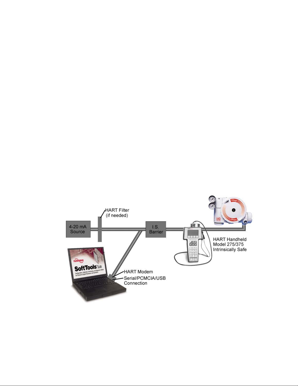
Instrument to Computer Connection
Make the physical connection between the PC and the positioner. Locate an available
serial, PCMICIA or USB communications port on the computer and plug a HART modem
into it. Attach the other end of the HART modem cable to the appropriate device or
interface.
Many new computers (especially laptops) no longer have serial or PCMICIA connections,
but do have USB ports. If the user already has a serial HART modem, a USB to RS 232
adapter is an inexpensive alternative to purchasing a new USB HART modem. Not all USB
to RS 232 adapters communicate properly with the RS 232 HART modems. Flowservesupported USB converters at this time include: Startech – Model #: ICUSB232, Belkin –
Model #: F5U103, and Mactek – Model #: 010031.
USB adapters/modems typically come with driver software (usually on a CD). The user will
be prompted to install the USB driver(s) when the USB adapter/modem is used for the first
time. USB driver software is typically USB port specific. This means that if a laptop has two
USB ports, and the user connects the adapter to USB Port 1 during driver installation, the
adapter will only work on USB Port 1 after the driver(s) are installed. If the adapter/modem
is later connected to USB Port 2, the adapter/modem may not work. To solve this problem,
the USB adapter/modem should be connected to the same USB port every time SoftTools is
used.
RECOMMENDATION: Users with multiple USB ports on their computers will want to use
the same USB port every time they use SoftTools, and make sure that the proper USB
adapter/modem drivers are installed for this USB port.
VLAUG001-00 ©Flowserve Corporation, Valtek Control Products, Tel. USA 801 489 8611 5 of 21
Page 6

Chapter 3: Startup
Boot the system in preparation for starting the application:
Using SoftTools 7.0
1. From the Windows Toolbar, click on Start. Select
Programs/Flowserve/SoftTools/TechCheck. The TechBridge splash screen,
followed by the TechCheck splash screen displays. The application will initialize
and install the TechBridge, BridgeEx, and Alert Tool icons into the Windows
System Tray.
2. The Log In dialog will appear. Type “trial” without the quotes into the Password
field. Click OK to finish logging into the system.
Figure 1 TechCheck Login
Using SoftTools TechCheck
Figure 2 TechCheck Main menu
Before attempting the following procedure, see Disabling FIFO Buffers (Page 18).
Please follow these instructions to make your initial connection to a field device on a
HART modem.
VLAUG001-00 ©Flowserve Corporation, Valtek Control Products, Tel. USA 801 489 8611 6 of 21
Page 7

1. Select Connections from the TechCheck Main menu.
2. Select Set Up Field Network.
3. Select the HART icon.
4. Right-click the HART icon.
5. Select Add.
6. Select and click Server Port.
7. On the ADD SERVER PORT window, use the Com Port pull down box to select
the RS-232 port this connection will use. In the case where you are using a USB
converter, select the communication port created by the installation of the USB
hardware.
NOTE: Some USB converters will require you to check the RTS delay check box.
8. Click OK.
9. A PORT will be added to the Field Network tree.
10. Select the newly added PORT icon.
11. Right-click the PORT icon.
12. Select Scan.
13. Select and click Field Devices.
14. On the Search for a Field Device to Add window, click Start. The program scans
from the Start at Field Address to the Stop at Field Address.
15. Responding devices appear in the grid on the bottom of the window. Usually,
only one device will be attached to a modem.
16. Once the device is found, click Stop to quit scanning in order to avoid a lengthy
search routine.
17. Click the Close just under the Estimated Time Remaining indicator.
18. Click the Add button to add the device to the Field Network Tree.
19. Select the newly added device.
20. Click Install to add the device to the TechCheck device selection list.
21. Click Close to return to TechCheck.
You are now ready to use the TechCheck application tools.
Return to the TechCheck main menu and click on Tools. For the initial use of SoftTools
TechCheck, select Use Configurator and continue with the following instruction titled
Configurator Tool. With a previously configured and calibrated device, select from among
any of the SoftTools Suite application tools.
Using the Configurator Tool
After selecting and establishing communications with a device, configure the positioner. If
the positioner was shipped factory-mounted to a valve, it is pre-configured and calibrated to
work as is.
If working with a new positioner or retrofitting a positioner onto a different valve, parameters
must be set to ensure that it will control the valve properly.
1. From the TechCheck main menu window, click on Tools.
2. Select Use Configurator. Or,
VLAUG001-00 ©Flowserve Corporation, Valtek Control Products, Tel. USA 801 489 8611 7 of 21
Page 8

3. Click on the Configurator toolbar button for direct access to the Configurator
window.
The Configurator window contains three tabs: Actuator, Positioner, and Valve. Click on
each tab to select and configure the settings for each component.
Figure 3 TechCheck Configurator window (Actuator Configuration Tab shown)
Click on the Actuator tab to display the Actuator Configuration screen. Check to make
certain the actuator information and actions are set correctly.
1. From within the Actuator screen, click on each combo box to ensure that the
selections correspond to the installed actuator information.
2. From within the Mechanical Action screen, click on each combo box to ensure that
the selections correspond to the mechanical configuration of the device.
WARNING! Incorrect settings and/or overriding the DIP switches on the Logix positioner
may cause the valve to stroke suddenly or become unstable.
Click on the Positioner tab to display the Positioner configuration screen. Click on each
representative button to view and/or edit the configurable settings displayed within their
respective windows.
Figure 4 TechCheck Configurator window (Positioner configuration tab shown)
VLAUG001-00 ©Flowserve Corporation, Valtek Control Products, Tel. USA 801 489 8611 8 of 21
Page 9

For the initial configuration of the device, Flowserve suggests the following configurable
features of the positioner configuration screen receive attention:
1. Click on Minimum Position Cutoff to display its respective window. This feature
prevents the valve from throttling near the seat. If the Control command becomes
less than the Minimum Position Cutoff value, the positioner closes the valve. To
use this feature, enter a desired cutoff value in percent of stroke. Click on the
Apply button.
2. Click on Model to display its respective window. The Logix 1200e and 3200IQ
series positioner is available in two models: The standard model with HART
communications and no pressure sensors. The advanced model with Port 1 and
Port 2 actuator pressure sensors and HART communications. Selecting the
incorrect model prevents SoftTools from using all of its features.
3. Click on Soft Limits to display its respective window. When soft limits are applied,
the positioner restricts Control Command to the given limits. If soft limits are to be
used, enter the High Limit and Low Limit set-points to the desired level and click on
the Apply button.
4. Click on Stroke Characterization to display its respective window. Custom
Characterization enables the positioner to change its output signal as a function of
the input signal. This allows the stroke movement of the closure member to be
customized.
Click on the Valve tab to display the Valve Configuration screen. Click on each
representative button to view and/or edit the configurable settings displayed within their
respective windows.
Figure 5 TechCheck Configurator window (Valve configuration tab shown)
1. Use the Body and Trim selections to display their respective windows and ensure the
selections correspond to the installed valve body and trim information.
2. Preventive Maintenance and User Information selections allow user-defined
configuration of closure member travel and cycling limits and units of measure
throughout the device.
VLAUG001-00 ©Flowserve Corporation, Valtek Control Products, Tel. USA 801 489 8611 9 of 21
Page 10
Reset
If it becomes desirable to reset the device to the factory default settings, proceed as follows:
From the TechCheck Configurator menu, click on Configurator and select Reset
Configuration.
From the Reset window, you may set all non-volatile memory to factory defaults. Any
custom configurations or settings are lost and the positioner will operate as a standard
model (read the warning within the window). To reset the device, click on the Reset
checkbox and click Apply.
Using the Calibrator Tool
The Calibrator Tool consists of several separate calibration windows and allows calibration
of the actuator pressure sensors, the 4-20 mA current loop, and the closure member stroke
position sensor. Select and perform each of the calibrations to ensure correct operation of
the device. An additional function provides a means to check the device calibration.
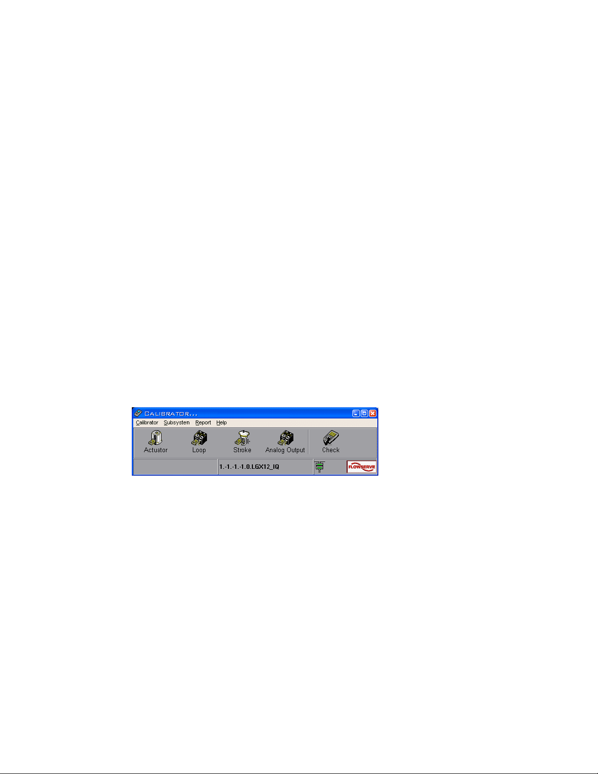
1. From the main TechCheck window menu, click on Tools.
2. Select Use Calibrator. Or,
3. Click on the Calibrator toolbar button for direct access to the main Calibrator
window.
Figure 6 TechCheck Calibrator main menu window
To select a specific calibration type:
1. From the main TechCheck Calibrator window menu, click on Subsystem.
2. Select the type of calibration desired. Or,
3. Click on a toolbar button for direct access to the desired calibration type.
Click on Calibrate Actuator Pressure Sensor to display the Calibrate Actuator Pressure
Sensor window. This calibration procedure is available only on 121X and 321X (advanced)
models of the Logix positioners, and effects the calibration of the actuator pressure sensors.
VLAUG001-00 ©Flowserve Corporation, Valtek Control Products, Tel. USA 801 489 8611 10 of 21
Page 11

Figure 7 TechCheck Calibrator (Calibrate Actuator Pressure Sensor window)
To perform an actuator pressure sensor calibration:
1. Type in the supply pressure if the displayed pressure differs from the actual
pressure.
2. Click on the Start button. The attached device automatically performs the
calibration using the embedded internal calibration data.
NOTE: You must complete the entire procedure. The positioner is "offline" during
calibration and does not return to service until the procedure is complete.
Click on Calibrate Current Loop to display the Calibrate Current Loop window. Perform
this procedure to correctly calibrate the 4-20 mA input signal. This is a linear two-point range
calibration on the input signal sensed by the Logix positioner. It requires that you set both
the minimum and maximum current levels the positioner will sense as a command signal.
Figure 8 TechCheck Calibrator (Calibrate Current Loop window)
VLAUG001-00 ©Flowserve Corporation, Valtek Control Products, Tel. USA 801 489 8611 11 of 21
Page 12
To perform a current loop calibration, follow the directions in the calibration wizard:
1. Set the variable current source to the desired absolute 0% command signal
(usually 4 mA). Click the 0% level Accept button.
2. Set the variable current source to the desired minimum (usually 4 mA). If split-
ranged application, minimum may be different (e.g. 12 mA).
3. Set the variable current source to the desired 100% command signal (usually 20
mA). Click the 100% level Accept button.
NOTE: You must complete the entire procedure. The positioner is "offline" during
calibration and does not return to service until the procedure is complete.
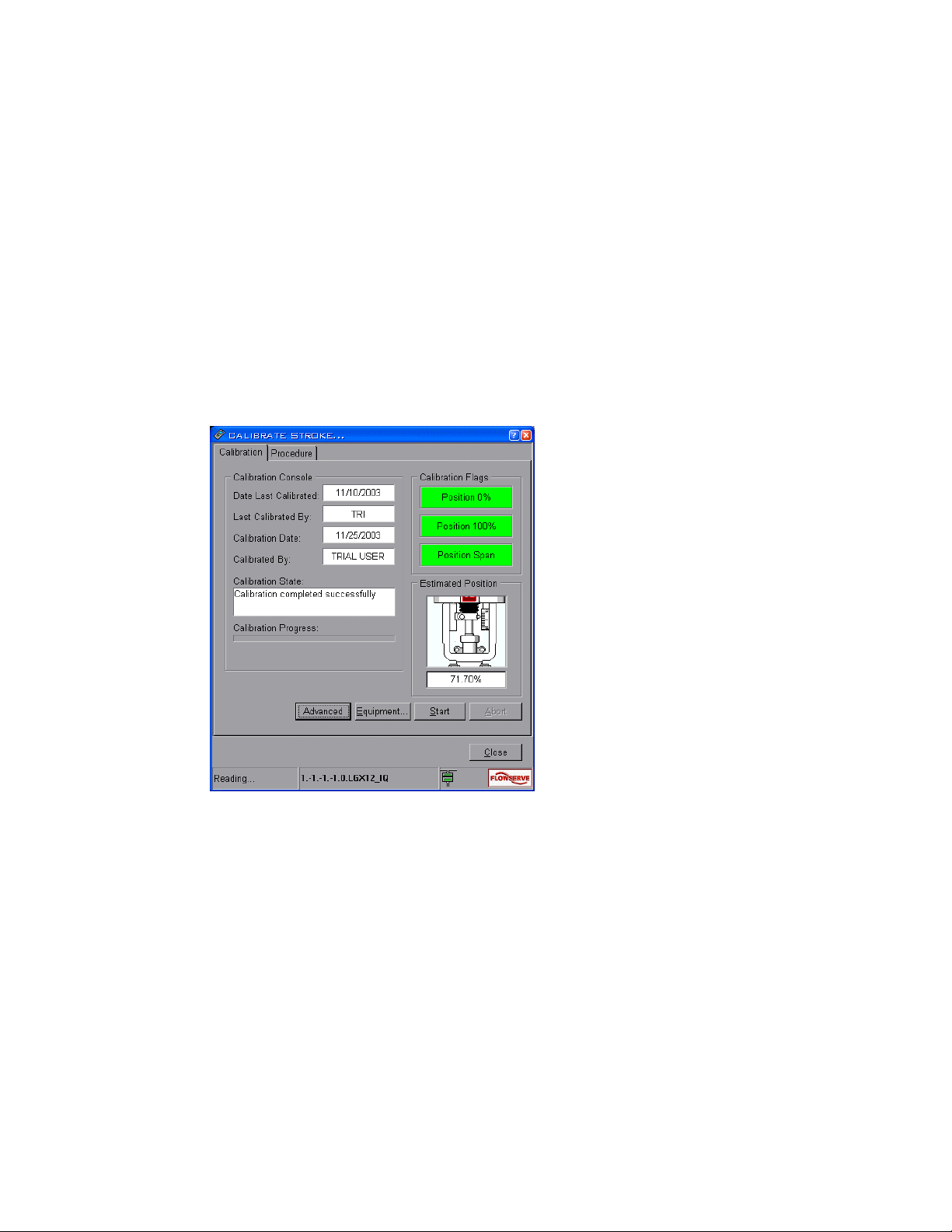
Click on Calibrate Stroke to display the Calibrate Stroke window. The stroke calibration
procedure moves the valve to a closed position and then to an open position. The positioner
measures closure member position at the two points to ascertain each exact position,
thereby correctly calibrating the stroke position sensor.
Figure 9 Stroke calibration window
To perform a stroke calibration on a "double-acting" actuator:
WARNING! This procedure causes stroke movement to occur. Follow your company
guidelines to assure the safety of personnel and processes before proceeding.
1. Click on the Start button. The stroke calibration procedure is performed
automatically.
Note: You must complete the entire procedure. The positioner is "offline" during calibration
and does not return to service until the procedure is complete.
VLAUG001-00 ©Flowserve Corporation, Valtek Control Products, Tel. USA 801 489 8611 12 of 21
Page 13

Click on Check Calibration to display the Check Calibration window. The check calibration
procedure verifies the completed calibration performed to the attached device.
Figure 10 TechCheck Calibrator (Check Calibration window)
Before performing this procedure, it is important to have performed the Actuator Pressure
Sensor, Current Loop, and Stroke calibrations. This procedure will stroke the closure
member to five separate positions, wait for the selected Settling Time, and then compare
Command to Position to affect a Pass/Fail calibration rating.
To perform a Check Calibration on a "double-acting" actuator:
WARNING! This procedure causes stroke movement to occur. Follow your company
guidelines to assure the safety of personnel and processes before proceeding.
1. Using the spin button, select the desired Settling Time for each position.
2. Click on the Start button to initiate the procedure.
Calibration reports may be generated using additional functionality built into the Calibrator
Tool.
1. From the main TechCheck Calibrator window menu, click on Report.
2. Click on Create Report to display the Create Report window.
3. Using the available combo boxes within the window, select the desired criteria with
which to generate a calibration report.
VLAUG001-00 ©Flowserve Corporation, Valtek Control Products, Tel. USA 801 489 8611 13 of 21
Page 14

Using the Condition Tool
While the positioner controls the device, you may monitor the ongoing status of its
relationship with the closure member.
1. From the main TechCheck window menu, click on Tools.
2. Select View Condition. Or,
3. Click on the Condition toolbar button for direct access to the Condition window.
4. The Condition window contains dual functions: Within the Monitor Status tab,
monitor the closure member position and positioner action in real time, while the
valve is functioning in a process loop. Within the View Variables tab, alternately
select among and view individual variables.
Figure 11 Condition window (Monitor Status tab selected)
Within the Device Status panel, the 4-20 mA dynamic display indicates the analog command
to the positioner (in percentage). Changing the current loop level will cause the value
indicated in the 4-20 mA display to change. The 4 mA should read approximately 0% and
20 mA should read approximately 100%. Perform a loop calibration to eliminate any error
(refer to the Calibrator tool).
VLAUG001-00 ©Flowserve Corporation, Valtek Control Products, Tel. USA 801 489 8611 14 of 21
Page 15

The Position indicator bar on the left side of the panel represents the position of the closure
member in percent of full stroke. The indicator tracks the closure member position as the
valve is stroked. If a large deviation exists between Command In and Control command (the
actual command the positioner is using to position the valve), check to see if Custom
characterization is active. If not, two options are available to correct it.
• Wait a few minutes. The positioner has an integrator built into its control algorithm
that will slowly take out any deviation between the Command In and Control
commands.
• Tune the positioner. Refer to “Positioner Tuning” in the Configurator tool for
detailed information and instruction.
Selecting a Command Source
The positioner operates using either an analog or a digital command source. Analog
command source indicates that the Control command originates from a 4-20 mA current
source. Digital command source indicates that the Control command originates from a
computer or other source that is capable of sending the command via the HART
communication connection. Select the command source as follows:
1. Click the combo box labeled Source.
2. Select Digital or Analog as desired. The program indicates the success of the
source change.
Entering a Digital Command
For fine adjustments to the digital positioner, use the Command In spin button edit control.
1. Use the spin buttons within the control labeled Command In to
increment/decrement the current value.
2. Highlight the value in the control box. Type in a new digital command percentage
and press ENTER to transfer the new value to the positioner.
Selecting a Step Size
Set the step size as follows:
1. Click the combo box labeled Step Size.
2. Select the step size desired for the particular application. Sizes range from 10
through 1 to 0.1, as a percent of stroke. Press ENTER to transfer the new value
to the positioner.
The program uses the newly selected step size for all subsequent adjustments made to the
digital command percentage.
Viewing Individual Variables
To view individual variables, select the View Variables tab.
1. Choose a variable to view by alternately clicking on each button edit control
beneath the Variable # label.
VLAUG001-00 ©Flowserve Corporation, Valtek Control Products, Tel. USA 801 489 8611 15 of 21
Page 16

2. Select from a grid containing a list of variables available for viewing. Each choice
made displays the variable number with its corresponding description and current
value.
Figure 12 Condition window (View Variables tab selected)
Using the Alert Display
All windows involved in communication with the instrument contain the Alert Display LED
visible within the status bar to the left of the Flowserve logo. If it becomes active, it blinks
red. Place the cursor over it and right click the mouse. The Alert Display window shows
and allows the user to view additional information and/or acknowledge any errors.
Security Administrator
If you wish to establish separate levels of access for users, proceed with the following:
1. Right-click on the TechBridge tray icon (this icon is usually located in the bottom
right hand corner of the screen on the windows taskbar), and select Open
Security Administrator from the pop-up menu. The Security Check window
displays. Select Admin from the Administrator ID: combo box, and type your
user password into the Password: edit box. The Security Administrator window
displays.
VLAUG001-00 ©Flowserve Corporation, Valtek Control Products, Tel. USA 801 489 8611 16 of 21
Page 17

Figure 13 Security Administrator window
5. To insert a new user, click on the Insert tool button. The Insert User window
displays.
Figure 14 Security Administrator Insert User window
6. Type a name into the User Name edit box. Using the Security Level combo box,
select a user level designating access permissions. Type a password for the new
user into the Password edit box and re-type the same password into the Verify
Password edit box. Click on OK.
7. To edit a user, click on the Edit button. The Edit User window displays.
VLAUG001-00 ©Flowserve Corporation, Valtek Control Products, Tel. USA 801 489 8611 17 of 21
Page 18

Figure 15 Security Administrator Edit User window
8. Type a name into the User Name edit box. Using the Security Level combo box,
select a user level designating access permissions. Type a password for the
edited user into the Password edit box and re-type the same password into the
Verify Password edit box. Click on OK.
9. To delete a user, click on the Delete tool button. A confirmation window displays.
Click on Yes to delete the user.
Figure 16 Security Administrator Confirm window
Using the Context-Sensitive Help System
To access the SoftTools 7.0 help system:
From any SoftTools menu, click on the Help menu item.
Click on Contents and Index to view the Contents and Index window of the help
system, or…
Select a control on which you wish to receive help and press F1 (it must be a control
that can receive focus). A pop-up window containing help displays.
From the keyboard, access the Contents and Index window of the help system by
pressing F1.
Disabling FIFO Buffers
With the advent of advanced serial port hardware, Microsoft
the user the ability to configure how data is transferred out a serial port. A
communication port works in units of characters. A single character is represented by
a variable number of bits. The new hardware is capable of caching several characters
before actually transmitting them out the port. The concept works well for devices that
can handle more than one character at a time. Here-in lies the problem. Due to timing
constraints in the HART protocol, the Logix positioner can only receive one character at
®
Windows gives
VLAUG001-00 ©Flowserve Corporation, Valtek Control Products, Tel. USA 801 489 8611 18 of 21
Page 19

a time. In order for the positioner to receive data correctly, the user must turn off the
FIFO buffers. The following procedure assists the user in turning off FIFO buffers.
Microsoft Windows NT
1. Click Start.
2. Click Settings.
3. Double click Ports.
4. Click Advanced on the Ports dialog.
5. Uncheck the FIFO check box.
6. Click OK.
7. Close the Port dialog.
8. Close the Control Panel.
9. Reboot the computer.
Microsoft Windows 98, 2000, and XP
1. Click Start.
2. Click Control Panel or Settings.
3. Double click System.
4. Click the Hardware tab.
5. Click the Device Manager button.
VLAUG001-00 ©Flowserve Corporation, Valtek Control Products, Tel. USA 801 489 8611 19 of 21
Page 20

6. From the device selection list, expand the Ports item.
10. Right click the communication port you desire to use with SoftTools.
NOTE: USB adapter cables and modems will have their own COM ports
assigned when the driver(s) are installed. This installation typically occurs the
first time the adapter or modem is connected, and the drivers are installed
using the manufacturer’s installation software (typically on a CD). This is not
usually COM Ports 1 or 2. Care must be taken to ensure that the correct COM
port is selected, or the FIFO buffers will be disabled for the incorrect COM Port.
11. Click Properties.
VLAUG001-00 ©Flowserve Corporation, Valtek Control Products, Tel. USA 801 489 8611 20 of 21
Page 21

9. Click the Port Settings tab.
10. Click the Advanced button.
11. Uncheck the Use FIFO buffers check box.
12. Click OK.
13. Click OK on the Properties dialog.
14. Close the Device Manager.
15. Click OK on the System Properties window.
16. Restart the computer.
Flowserve Corporation, Flow Control Division
1350 North Mountain Springs Parkway
Springville, UT, 84663
U.S.A.
801.489.8611
www.flowserve.com
VLAUG001-00 ©Flowserve Corporation, Valtek Control Products, Tel. USA 801 489 8611 21 of 21
 Loading...