

Page 1

PRS 9
Installation Instructions 810407- 00
Cycling Timer PRS 9
A Siebe Group Product
1
Page 2
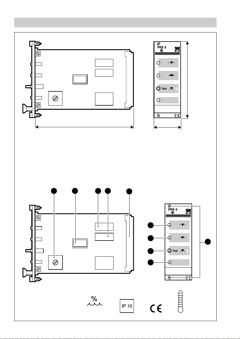
Dimensions/Parts Drawings
1 28.5
Fig. 1
169
A
B C D
E
30.01 (6TE)
I
H
G
F
J
2
Fig. 2
MAX 70°C
MAX 95%
Page 3

Key
A
Switch S1
B
Switch S2 PROGRAM SELECTION
C
Relay 2 ENERGIZED
D
Relay 1 DE-ENERGIZED
E
32 way Euro card connector
F
LED
G
Pushbutton TEST
H
LED VALVE CLOSED
I
LED VALVE OPEN
J
Fixing screws
TIME DELAY
OPERATION
3
Page 4

Contents
Page
Important Notes
Safety note ...................................................................................................................... 6
Warning ...........................................................................................................................6
Explanatory Notes
Scope of supply .............................................................................................................. 7
System description ......................................................................................................... 7
Function .......................................................................................................................... 7
Design ............................................................................................................................. 7
Technical data ................................................................................................................. 8
Installation
Design “c”/ “d” .................................................................................................................9
Attention..........................................................................................................................9
Tools ................................................................................................................................9
Wiring
Design “c”/ “d” ...............................................................................................................10
Wiring diagram ..............................................................................................................10
Key to wiring diagram ...................................................................................................10
Attention........................................................................................................................ 1 1
Note ..............................................................................................................................11
Basic Adjustments
Select opening mode of the valve ................................................................................ 12
Table 1 Opening mode of the valve ..............................................................................12
Adjust time delay ..........................................................................................................12
Table 2 Time delay........................................................................................................12
Commissioning
Warning .........................................................................................................................13
Check valve function .....................................................................................................13
Check wiring .................................................................................................................13
Apply mains voltage......................................................................................................13
Check test function .......................................................................................................13
Check switching function ..............................................................................................13
4
Page 5

Contents – continued –
Page
Annex
Warning.........................................................................................................................14
Fault finding list .............................................................................................................14
Declaration of conformity ..............................................................................................14
5
Page 6

Important Notes
Safety note
Use the cycling timer PRS 9 only in combination with GESTRA level switches
NRS 2-4. Installation must only be performed by qualified staff.
Qualified staff are those persons who – through adequate training in electrical
engineering, the use and application of safety equipment in accordance with
regulations concerning electrical safety systems, and first aid & accident
prevention – have achieved a recognised level of competence appropriate
to the installation and commissioning of this critical safety device.
Warning
The terminal strip of the PRS 9 is live during operation. This presents the
danger of electric shock. Cut off power supply before opening the
equipment and before inserting or removing the 19" slide-in unit.
6
Page 7

Explanatory Notes
Scope of supply
PRS 9, design “c”
1 Cycling timer type PRS 9
2 Guide rails
1 32pole screw-type connector
1 Installation instructions
PRS 9, design “d”
1 Cycling timer type PRS 9
1 Installation instructions
System description
The PRS 9 is an analogue/digital cycling timer. In combination with up to four level
switches type NRS 2-4/NRS 2-5 and a position-controlled limit switch the cycling
timer can, as part of a controlled draining system in a power station, control drain
valves as a function of time.
Function
Signals coming to the inputs of the level switches and the position-controlled limit
switch will be processed electronically, with the time delay adjusted in the equipment
being taken into account. Dependent on the adjustment the drain valve will be
controlled in one or two steps with a time delay.
Design
Design “c”
19" slide-in unit with guide rails and 32pole screw-type connector for installation in
19" magazine acc. to DIN 41494, part 5.
Design “d”
19" spare slide-in unit
7
Page 8

Technical data
Supply voltage
24 V DC
Power consumption
4 V A
Input
Three control inputs (volt-free relay contacts)
Control voltage 12 V DC
Output
2 volt-free relay contacts
Max. contact rating with a switching voltage of 24 V, 115 V and 230 V AC: 4 A
resistive, 0.75 A inductive at cos ϕ 0.5.
Max. contact rating with a switching voltage of 24 V DC: 4 A.
Service life of the relays: 30x10
6
switching cycles.
Indicators and adjustors
1 green LED
OPERATION, 1 red LED VALVE OPEN, 1 red LED VALVE CLOSED
1 pushbutton TEST (simulating alarm signalled by P1)
1 switch (on the circuit board) for program selection
1 switch (on the circuit board) for time delay setting
Protection
IP 10 to DIN 40050
Admissible ambient temperature
0°C to +70°C
Case
19" slide-in unit with front panel to DIN 41494 part 5 and rear 32 way Euro card
connector to DIN 41612 for installation onto 19" magazine.
Front panel: Aluminium
Wiring
via 32 pole screw-type connector at the back of the 19" magazine, max. conductor
size 1.5 mm
2
Weight
approx. 0.6 kg
8
Page 9

Installation
Design “c”/“d”
1. Install the guide rails and the screw-type connector in the 19" magazine.
2. Introduce the 19" slide-in unit onto the guide rails until it hits the stop.
3. Tighten the fixing screws .
Attention
To provide sufficient ventilation, ensure a minimum spacing of 20 mm
between adjacent units.
Tools
■
Screwdriver for slotted screws, size 5, completely insulated according to VDE 0680.
J
9
Page 10

Wiring
Design “c”/ “d”
Wiring is effected via the 32 pole screw-type connector.
Wiring diagram
PRS 9
4
5
1
Fig. 3
Key to wiring diagram
1
P2 Level switch NRS 2-4 or NRS 2-5 (24 V DC) from corresponding level electrode 2
2
Position-controlled limit switch of the drain valve
3
P1 Level switch NRS 2-4 or NRS 2-5 (24 V DC) from level electrode 1
4
Rel 2 for opening the drain valve
5
Rel 1 for closing the drain valve
10
2 3
Page 11

Attention
■
Fuse supply cable with T 2.5 mA.
■
When switching off inductive loads, voltage spikes are produced
that may impair the operation of control and measuring systems.
Inductive loads should be provided with commercial arc suppressor
RC combinations, e. g. 0.1 µF/100 Ω.
Note
Connect only volt-free relay contacts to the control inputs. The cycling
timer PRS 9 supplies a 12 V DC control voltage.
11
Page 12

Basic Adjustments
Select opening mode of the valve
Use switch S2 for selecting the opening mode, see table 1.
B
Table 1 Opening mode of the valve
Switch position Opening mode of the valve
1 Two-step opening of the valve
2 One-step opening of the valve
Adjust time delay
Use switch S1 for setting the time delay, see table 2.
A
Table 2 Time delay
Switch position Time delay
1 5 sec.
2 7.5 sec.
3 10 sec.
4 15 sec.
5 22.5 sec.
6 30 sec.
12
Page 13

Commissioning
Warning
The terminal strip of the PRS 9 is live during operation. This presents the
danger of electric shock. Cut off power supply before undertaking any work
at the equipment and before inserting or removing the 19" slide-in unit.
Check valve function
1. Drive drain valve manually into the mid-position.
2. Apply mains voltage for about 10 sec. – P1 and P2 must not give a signal – and
check whether the valve moves into the closed position.
Check wiring
1. Check whether the 19" slide-in unit has been properly introduced into the magazine.
2. Check whether the equipment has been wired in conformity with the mains voltage.
Apply mains voltage
1. Switch on the mains voltage and check the equipment for power supply.
The LED functions as visual check.
F
Check test function
1. Push button and check whether the valve is opening.
2. Press and hold down button until the valve has reached the position of the limit
G
G
switch and the actuator has been switched off.
3. Release button and check whether the valve returns to the closed position
G
after the preset time delay has elapsed.
Check switching function
To check the switching functions raise or lower the water level until the switchpoints
are reached or simulate the corresponding signals by disconnecting the control inputs
3
of P1 and P2 , Fig. 3
1. P1 and P2 are not giving signals: Check whether LED is illuminated, REL1 is
1
H D
energized and the valve is closing.
2. P1 or P2 is giving a signal: Check whether the LED is illuminated, REL2 is
I C
energized and the valve is opening.
3. P2 or – if the valve is controlled only by P1 – P1 is not giving a signal or the valve is
in the intermediate position, no LED illuminated: Check whether the LED lights
up after the time delay, REL 1 is energized and the valve is closing.
D
H
13
Page 14

Annex
Warning
The terminal strip of the PRS 9 is live during operation. This presents the
danger of electric shock. Cut off power supply before opening the
equipment and before inserting or removing the 19" slide-in unit.
Fault finding list
The LED is not illuminated after applying the mains voltage
F
Fault: The mains voltage has not been switched on.
Remedy: Switch on the mains voltage. Check the 19" slide-in unit for correct installation.
No or incorrect functions
Fault: The internal circuitry is defective.
Remedy: Replace the cycling timer.
Declaration of conformity
We hereby declare that the equipment PRS 9 conforms to the following European
guidelines:
■
LV guideline 73/23/EWG version 93/68/EWG
■
EMC guideline 89/336/EWG version 93/68/EWG
which are based on the following harmonised standards:
■
LV standard EN 60947-5-1: 1991
■
EMC standard EN 50 081-2, EN 50 082-2
This declaration is no longer valid if modifications are made to the equipment without
consultation with us.
Bremen, 28th April 1997
GESTRA GmbH
Dr. Anno Krautwald
Dr. Christian P olitt
14
Page 15

15
Page 16

GESTRA Gesellschaften · GESTRA Companies · Sociétés GESTRA · Sociedades Gestra · Società GESTRA
GESTRA Gesellschaften · GESTRA Companies · Sociétés GESTRA · Sociedades Gestra · Società GESTRA
Vertretungen weltweit · Agencies all over the world · Représentations dans le monde entier · Representaciones en todo el mundo · Agenzie in tutto il mondo
Vertretungen weltweit · Agencies all over the world · Représentations dans le monde entier · Representaciones en todo el mundo · Agenzie in tutto il mondo
España
España
GESTRA ESPAÑOLA S.A.
GESTRA ESPAÑOLA S.A.
Luis Cabrera, 86-88
Luis Cabrera, 86-88
E-28002 Madrid
E-28002 Madrid
Tel. 003491/5152032
Tel. (+34) 915152032
Fa x0 0349 1/41367 47 ; 515 203 6
Fax (+34) 914136747; (+34) 915 152 036
E-mail: gestra@gestra.es
Polska
Polska
GESTRA POLONIA Spolka zo.o.
GESTRA POLONIA Spolka z.o.o.
Ul. Schuberta 104, P.O. Box 71
Ul. Schuberta 104, P. O.B. 727
PL-80-172 Gdansk
PL-80-958 Gdansk 50
Tel. 004858/3061002 oder 30610 10
Tel. (58) 306 10 02
Fax 004858/3061003 oder 3063300
Fax (58) 306 10 03
E-mail: gestra@gestra.pl
France Portugal
France Portugal
GESTRA S.A.R.L.
10 Avenue du Centaure, BP 8263 CERGY
Flowserve Flow Control S.A.S.
F-95801 CERGY PONTOISE Cedex
10 Avenue du Centaure, BP 8263
Tél. (00 33) 01.34.43.26.60
F-95801 CERGY PONTOISE CEDEX
Fax (00 33) 01.34.43.26.87
Tél. 00331/3443 2660
Fax 00331/34432687
Great Britain
E-mail: gnation@flowserve.com
GESTRA (U.K.) LTD.
9-11 Bancroft Court
Italia
Hitchin, Hertfordshire, SG5 1PH
Tel. (0 14 62) 4316 81
Italgestra S.r.l.
Fax (0 14 62) 4203 96
Via Carducci 125
l-20099 Sesto San Giovanni (MI)
Italia
Tel. 003902/2410 12.1
Fax 003902/241012.460
ITALGESTRA S.r.l.
E-mail: info@italgestra.it
Via Carducci 125
l-20099 S.S. Giovanni (MI)
Tel. (02) 2 6297-0
Fax (02) 26 297460
GESTRA PORTUGUESA VALVULAS LDA.
Av. Dr. Antunes Guimarães, 1159
GESTRA PORTUGUESA V ALVULAS LDA.
P-4100 Porto
Av. Dr. Antunes Guimarães, 1159
Tel. (2) 6 1075 51
Porto 4100-082
Fax (2) 6 1075 75
Tel. 00351 22/6 19 8770
Fax 0035122/61075 75
USA
E-mail: gestra@gestra.pt
GESTRA Division
10 York Avenue
West Caldwell, NJ 07006
Tel. (9 73) 403-15 56
Fax (9 73) 403-15 57
®
®
GESTRA GmbH
Postfach 10 54 60
GESTRA GmbH
D-28054 Bremen
Münchener Str. 77
Hemmstraße 130
D-28215 Bremen
D-28215 Bremen
Tel. +49 (0) 421 35 03-0
Tel. + 49 (0) 421 35 03-0
Fax+49 (0) 421 3503-39 3
Fax +49 (0) 421 35 03-393
E-mail
gestra.gmbh@gestra.de
Internet www.gestra.de
Internet www.gestra.de
E-mail
gestra.gmbh@gestra.de
A Unit of Flowserve Corporation
A Siebe Group Company
810407-00/199c · ©1997 GESTRA GmbH · Bremen · Printed in Germany
16
 Loading...