

Page 1

USER INSTRUCTIONS
P4, P5, EP5, APEX 7000
Pneumatic Positioners
FCD PMENIM0006-00-A5 12/18
Installation
Operation
Maintenance
1
Page 2

EP5 Electro Pneumatic Digital Positioner FCD PMENIM0006-00-A5 12/18
Contents
1. Introduction 4
2. Storage instructions 6
3. Function 8
4. Installation 9
5. Connections 10
6. Cam adjustment 12
7. Calibration 13
8. Indicator adjustment 14
9. Front cover and indicator cover 14
10. I/P Unit (EP5/APEX 7000) 15
11. How to mount the I/P Unit to the positioner unit (P5/EP5) 16
12. Main tenan ce 17
13. Feedback unit (P5 or EP5) 22
14. Trouble shooting 23
15. Technical data 24
16. Spare parts 27
Apendix A 33
2
Page 3

EP5 Electro Pneumatic Digital Positioner FCD PMENIM0006-00-A5 12/18
Warning!
Special Conditions for Safe Use
The enclosure is made of aluminum and impact or friction caused by external objects
shall be avoided in the application.
Rubbing of the windows with dry fabrics shall be avoided when the positioner is used in
an IIC atmosphere in order to avoid potentially incendive static discharges.
The ambient temperature range for the positioner is -20˚C <Ta 85˚C
The I/P converter has to be installed in an enclosure that satisfies the following clauses:
Complies with ”electrostatic charge” requirements in EN 60079-0, clause 7.4
A suitable degree of protection minimum IP20 according to 6.1 in EN 60079-11
Shall not contain by mass, more than, 7.5% in total of magnesium according to clause 8.1
in EN 60079-0
According to descriptive document: IP-653.
Shall withstand dielectric strength test with 500V AC for 1 minute according 6.3.12 in EN
6007 9 -11.
3
Page 4
EP5 Electro Pneumatic Digital Positioner FCD PMENIM0006-00-A5 12/18
Always check www.pmv.nu for latest edition of manual.
1. Introduction
P4
The P4 is a pneumatic valve positioner for double acting actuators, rotary or linear. It can also be
used for single acting applications by simply plugging one of the outlet ports, C1 or C2.
It features a standardized foot print, external zero adjustment, gold plated spool valve, positive
internal pressure and a bright visible position indicator. The simple, sturdy design with few moving
parts together with the well proven spool valve design provides long and trouble free operation.
Together with the unit, a wide range of mounting kits are offered for quarter turn and linear
applications.
Calibration and set up is quick and simple, all done by thumb wheels. The unit requires a minimum
of maintenance and the only tool needed is a flat screw driver.
For installation of gauges T-connectors are required.
Option
Option
4
Page 5
EP5 Electro Pneumatic Digital Positioner FCD PMENIM0006-00-A5 12/18
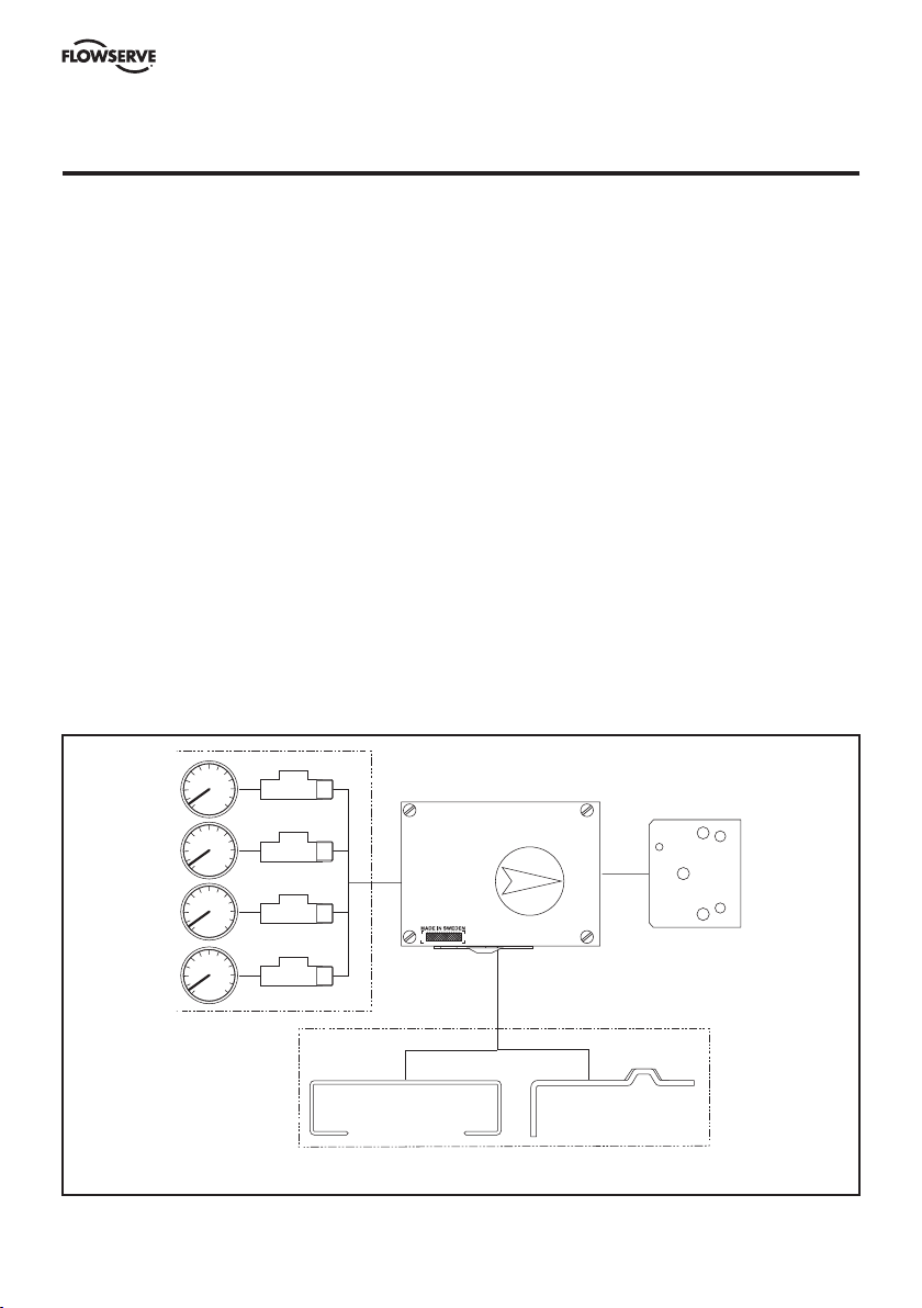
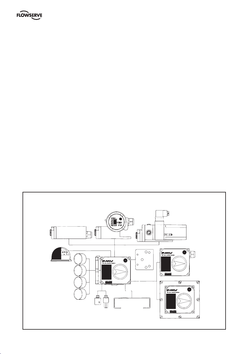
P5
The base unit of the system is the pneumatic positioner, used in either single or double acting
applications. P5 comes standard with a high gain spool valve assembly, gauge ports and an O-ring
sealed housing.
The modular design concept allows for easy addition of accessories such as I/P converter and/or a
feedback package, both which are isolated from the basic pneumatic unit. These accessories can be
factory or field mounted.
Ease of calibration and maintenance are built into to the design with easily accessible span and zero
adjustment, and very simple parts replacement.
EP5
The EP5 has same features and benefits as the P5 positioner. It’s modular to suit several
applications, General applications, intrinsically safe, explosion proof and fail freeze versions are
offered.
Standard or I/S
I/P-converter
module
Dome
indicator
Gauges
Explosionproof I/P module
P5 pneumatic positioner
Spindles
Mounting bracket
5
Mounting
adapter
plate
Fail Freeze
I/P Module
F5 feedback module
F5 Explosion Proof
Page 6

EP5 Electro Pneumatic Digital Positioner FCD PMENIM0006-00-A5 12/18
2. Storage instructions
PMV Positioner and feedback module storage and handling procedures
PMV Positioners and feedback modules are precision instruments which should be stored and
handled accordingly to avoid problems or damage.
Electro-pneumatic positioners/feedback modules contain electronic components which can be
damaged by exposure to water. Appropriate precautions should be taken to protect units while in
storage.
Warehouse storage
Stored in original PMV shipping containers, units should be stored in an environmentally controlled
area, i.e. clean, cool (15-26°C, 60-80°F) and dry, out of direct sunlight or weather exposure.
Field storage
Note: Once the air supply to the positioner is connected and turned on, internal air bleed will
prevent the ingress of moisture and protect the unit from corrosion. It is recommended that the air
supply be left on at all times.
• If units are installed immediately, turn, and leave on, the air supply.
• If positioners must be stored outdoors, tighten all covers which may have loosened in shipment,
make sure all open enclosure entry points are sealed.
Feedback modules should have cover tightened and conduits entries sealed. Positioners/Feedback
modules should be wrapped and sealed air and watertight with desiccant inside the plastic, units
should be securely covered with an opaque cover and not exposed to direct sunlight, rain or snow.
Pneumatic positioners
Units should have all ports sealed and be protected from direct exposure to weather.
For long term storage (>1 month) or overseas shipment units should be protected with plastic and
desiccant.
Potential damage mechanism
When units are stored in hot, humid climates, the daily heating/cooling cycle will cause air to
expand/contract and be drawn in and out of the positioner/feedback housing.
Dependent on the local temperature variations, humidity and dew points and time in storage
condensation could occur and accumulate inside on the I/P Converter causing erratic operation
or failure due to water and corrosion. The potential for condensation damage is especially high in
southern climates and aggravated if units are exposed to direct sunlight.
For further assistance, please contact you nearest PMV ofce.
6
Page 7
EP5 Electro Pneumatic Digital Positioner FCD PMENIM0006-00-A5 12/18
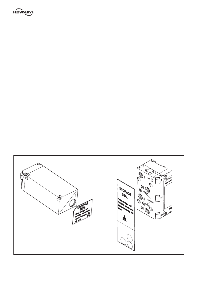
Storage Seal (P5/EP5)
P5/EP5 is supplied with all enclosure entry points sealed. The seal is only a storage seal, not to be
used as seal when P5/EP5 is in operation. If Storage Seal is removed or damaged, make sure all
open enclosure entry points are proper resealed before further shipping or storage.
Use circular stickers marked I, S and OUT, supplied on Storage Seal or vapour proof tape.
P5
Remove Storage Seal from connection block, mount positioner on actuator/valve, make
connections according to section 5, (Page 10). Calibrate span and Zero according to section 7,
(Page 13).
Clean any oil/debris off the connecting block, then reseal open enclosure entry ports, use circular
stickers marked I, S and OUT, supplied on Storage Seal or vapour proof tape.
EP5
Follow P5 instructions as above. Remove Storage Seal for conduit entry IE, connect input signal
cable and install proper cable gland to secure the units sealing.
IP5 seal
P5 seal
7
Page 8
EP5 Electro Pneumatic Digital Positioner FCD PMENIM0006-00-A5 12/18
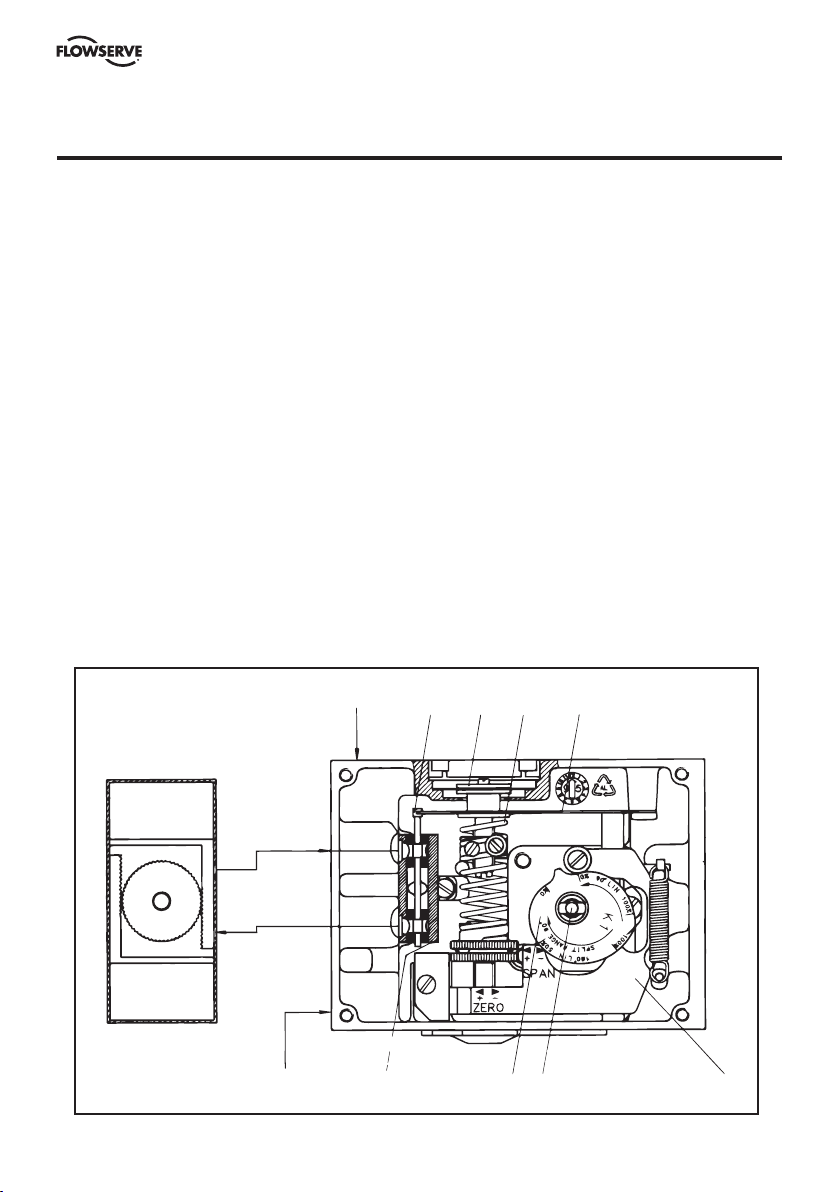
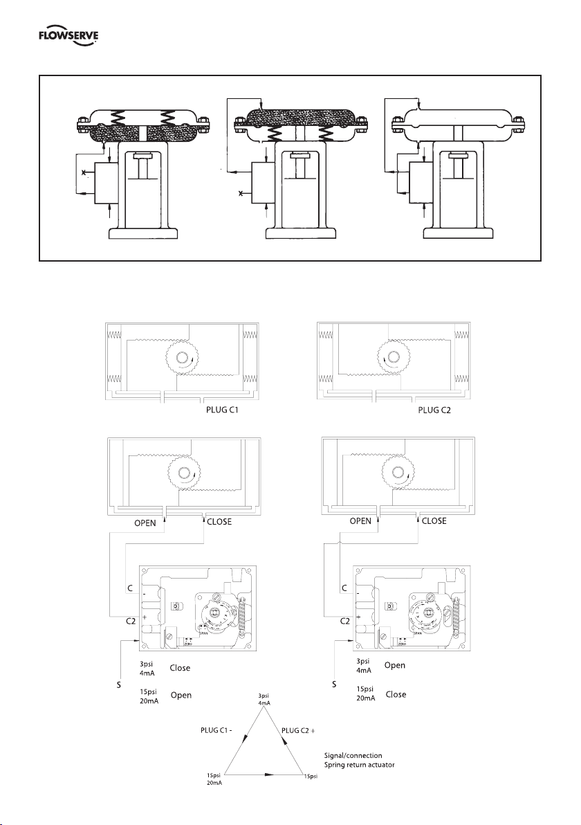
3. Function
The P4 and P5/EP5 operates on a force balance principal. Force is originated by the signal pressure
transmitted through a diaphragm on to the balance arm. The opposing force is achieved through the
feedback spring and is proportional to the position of the lower arm.
The lower arm position is determined by the position of the cam which is secured to the spindle and
connected to the actuator shaft thus providing the feedback from the actuator/valve. When these
two forces are equal, the balance arm and the spool in the pilot valve are in a neutral position — the
complete unit is in a balanced position. Air is supplied to the pilot valve through port S, and controls
the air flow through ports C1 and C2
Assume an equilibrium position.
An increased control pressure will deflect the diaphragm 1 down, compressing the feedback spring
3. The balance arm 2 moves the spool 7 in the pilot valve 8 furnishing supply air to the actuator,
while at the same time air is exhausted from actuator and is vented to atmosphere through the
pilot valve and the OUT port . With the increased supply air, the actuator rotates (or moves linearly)
moving the positioner spindle 6. The spindle and cam 5 rotate, forcing the lower arm 4 upwards
compressing the feedback spring 3. This motion will continue until the two forces are equal and the
unit is in an equilibrium position.
I
S
7312
4658
8
Page 9

EP5 Electro Pneumatic Digital Positioner FCD PMENIM0006-00-A5 12/18
4. Installation
Air requirements
Maximum supply pressure is 1 MPa (150 psi). Supply air shall be clean, dry and free from oil, water,
moisture, foreign parts and debris.
The air shall be freeze-dried or similar to a dew point of at least 10°C (18°F) below lowest expected
ambient temperature. The air shall comply with standard: DIN/ISO 8573-1-2001 3.2.3.
A <40μ filter/regulator is recommended to be installed as close to P4/P5/EP5 as possible to ensure
proper supply air quality.
Before making pneumatic connections to the positioner, it is recommended that the supply air lines
are opened up and allowed to vent for 2-3 minutes to clear any debris from the line. It is further
recommended that a large paper bag is used to collect any oil or humidity that may be present in
the line during this purging, direct the air flow into the bag. Should excessive amounts of oil and/or
humidity be present at this stage, a review of the pneumatic system should be carried out and the
problem corrected.
Poor air quality is one of the major causes of premature failure of pneumatic equipment.
Installation
P4 and P5/EP5 mounts on to the actuator using either the ISO F05 holes 4 and a PMV ISO mounting
kit or by using the optional mounting adaptor and screws 5 to mount P5 on to existing PMV
mounting kits.
Proper alignment of the positioner spindle to the actuator shaft is very important since improper
alignment can cause excessive wear and friction to the positioner.
P5/EP5 only
The spindle/positioner shaft assembly allows for quick and simple spindle changes. To ensure the
proper connection, the spindle 3 has a spring clip 2 that must be properly installed. A solid ”click”
should be felt when assembling the two pieces insuring that the two flats 1 are engaged into the
positioner shaft groove.
The spindle can be removed, by inserting two screwdrivers under the two tapered surfaces of the
spindle and bending carefully. When the spring clip releases the spindle will eject.
P4/P5 P5/EP5
2
1
3
5 4
9
Page 10
EP5 Electro Pneumatic Digital Positioner FCD PMENIM0006-00-A5 12/18
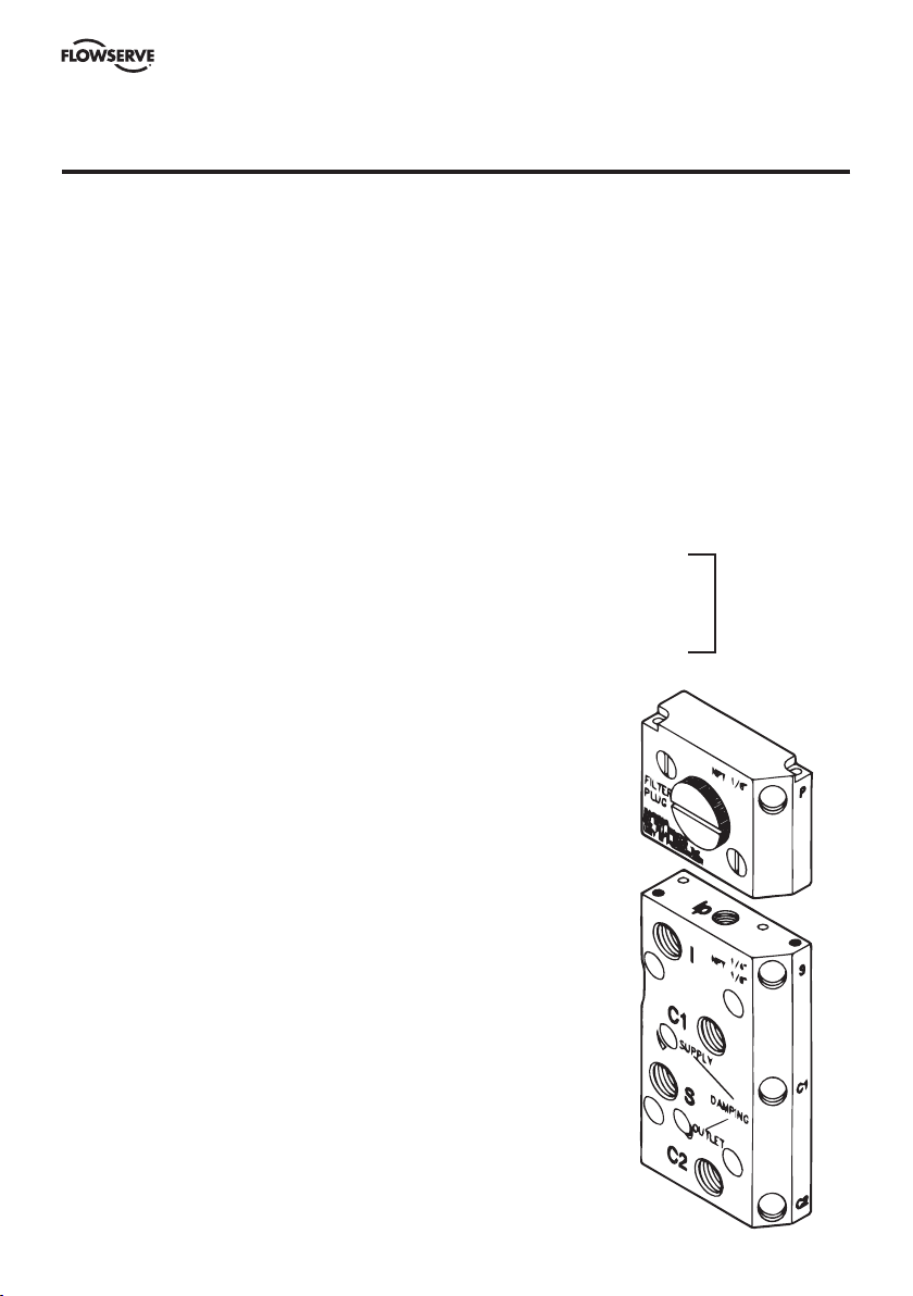
5. Connections
Air connections are tapped for 1/4” G or NPT male connectors and are clearly marked.
Gauge ports are for 1/8” G or NPT.
We recommend use of Loctite® 577 or similar user preferred for sealing.
Electrical connection on I/P unit accepts 1/2” NPT or PG 13,5 (M20) cable gland.
Port I Input instrument pneumatic signal 20-100kPa (3-15 psi)
Port S Supply air, maximum 1 MPa (150 psi) Minimum 0,15 MPa
(21 psi) for EP5
Port C1, C2 Actuator connections (0,2-1 MPa). C2 opening port.
For single acting operation plug port C1 for increasing signal to open valve. Plug C2 for decreasing
(reverse) signal to open valve.
OUT Exhaust air port. Do not block! Exhaust filter optional.
Port Ip Gauge port for pneumatic input signal.
Port I
Input electric signal (4-20 mA) (On the I/P unit.)
E
Port P Gauge port for I/P unit output pressure ( On the I/P unit)
Ports Ip, P, S, C1 and C2 are sealed with plugs. To install gauges,
unscrew plugs and replace with gauges.
P5/EP5 only
Port OUT is for venting the unit. All air from the positioner, actuator
and I/P unit is vented to atmosphere through this port. Do not block
this port. A high flow silencer or an exhaust pipe can be connected
to this port to prevent foreign objects from entering and blocking
the units exhaust. Connector in exhaust port must not have less
than 9 mm (3/8“) orfice.
When using gases other than air for supply — Please contact PMV.
On EP5 (P5 with I/P unit installed) I/P unit is supplied with air
from port S. Port I is automatically sealed off and protected. No
connection shall be made to this port. See pages 13 and 14 for more
information.
10
Page 11
EP5 Electro Pneumatic Digital Positioner FCD PMENIM0006-00-A5 12/18
Reverse function
C1
C2
S
X = Port plugged
I
Direct function
Air to open
C1
C2
S
C1
C2
II
S
Direct function
Air to close
Spring
Return
Double
acting
11
Page 12

EP5 Electro Pneumatic Digital Positioner FCD PMENIM0006-00-A5 12/18
6. Cam adjustment
With the cover and indicator removed, loosen the screw 1 and turn the cam locking nut 2
counterclockwise until the cam loosens. Adjust the cam 3 as desired making sure that the ball
bearing 4 always is riding on an active lobe on the cam. To secure the cam, make sure that screw 1
is backed out from the locking nut 2 then finger tighten the locking nut and tighten screw 1. Install
and adjust the indicator and reinstall cover.
2
1
Correct
1-2 mm (1/16")
4
Incorrect
3
Splined cam
As an option it is possible to configure the P5 with a splined cam. This design improves how
the cam is engaged to the shaft and will improve performance. The splined cam will generate an
increased safety in critical applications. See order code for more information how to order.
12
Page 13

EP5 Electro Pneumatic Digital Positioner FCD PMENIM0006-00-A5 12/18
7. Calibration
P4/P5/EP5 is when shipped from PMV pre-calibrated for 90 ±0,5 deg rotation, (can also be 30, 45
or 60 deg, see installed cam). For most applications the valve closed position is more critical than
valve open position, most attention should be paid at valve closed position. Always start calibration
procedure by applying 0 % input signal, then adjusting zero. P4/P5/EP5 is calibrated by turning
thumb wheels 1 & 4.
Arrows on arm 5 indicate turning direction
of thumb wheels.
< “+“ = Increase zero/span
> “–“ = Decrease zero/span
Calibration procedure
Check cam seating, section 6 before starting calibration
procedure.
1. Apply 0 % input signal (0% = 20 kPa/3 psi or 4 mA)
2. Wait for steady state.
3. Adjust zero by turning the silver (lower) thumb wheel
4 with finger or with screw- driver 7 from the outside.
4. Apply 100% input signal (100% = 100 kPa/ 15 psi or
20 mA)
5. Wait for steady state then memorize result.
6. Apply 0% input signal.
7. Adjust span if necessary. This is done by first loosing
screw 2, then turning the yellow (upper) thumb wheel
1 “+“ or “–“ and finally tighten screw 2. Spring top
must not be in contact with spring guide 3.
8. Check zero and adjust if needed.
9. Repeat steps 2 to 8 until desired calibration is
achieved.
5
4
6
7
3 1 2
For calibration of APEX 7000 please see
appendix A Calibration Procedure APEX 7000
13
Page 14

EP5 Electro Pneumatic Digital Positioner FCD PMENIM0006-00-A5 12/18
8. Indicator adjustment
P5/EP5: To adjust the indicator, take off front cover and pull the indicator upwards until it comes off
the Allen screw.
Before installing the indicator make sure that the Allen screw is tightened. Press the indicator on the
screw and adjust it by rotating clockwise to desired position.
P4: Loose screw, adjust indicator, tighten screw.
9. Front cover and indicator cover
The front cover of P5 is secured to the pneumatic unit with four captured screws and sealed with an
O-ring 1. The O-ring can be looped over notches 2 in the front cover to allow for drainage. There are
eight locations on the front cover where the O-ring can be looped. This O-ring system is common
to the Pneumatic unit , I/P unit and Feedback unit in the PMV Valve Control System P5. This unique
sealing system allows for complete sealing or draining of the units by changing the position of the
O-ring.
The indicator cover 3 is O-ring sealed and secured by a bayonet coupling. The indicator cover is
also used to secure the identification cover 4.
To remove the indicator cover turn it slightly counterclockwise until it loosens. Identification cover
and O-ring 5 are now removable.
When installing indicator cover and identification cover make sure that the O-ring is properly
engaged.
1
4315
2
14
Page 15

EP5 Electro Pneumatic Digital Positioner FCD PMENIM0006-00-A5 12/18
10. I/P Unit (EP5/APEX 7000)
WARNING!
Units installed in hazardous areas must
have proper approvals.
The I/P unit is mounted directly on top of the
positioner unit.
No external air supply is needed since the I/P
unit is supplied with air from the positioner
unit.
Port I on the positioner unit will be plugged
when the I/P unit and the appropriate gauge
block gasket installed. The I/P unit accepts a
4-20 mA input signal.
Fig 1
The I/P unit is equipped with a built in 30
micron filter (Fig 4).
Caution: Do not operate the unit without filter
and filterplug installed.
Ensure that wiring between I/P and terminals
are properly seated in rubber clamp.
Do not unscrew filterplug when the positioner is
pressurized.
Span and Zero for the I/P converter is factory
set and can not be adjusted
Fig 2
Fig 3
Fig 4
Fig 5
Fig 6
15
Page 16

EP5 Electro Pneumatic Digital Positioner FCD PMENIM0006-00-A5 12/18
11. How to mount the I/P Unit to the positioner unit (P5/EP5)
Switch off supply air and disconnect input signal – port I.
Loosen screws 3 and remove connection block 1, the gauge or plug from port Ip, the fitting from
port I and existing gasket 4. Carefully install gasket 6 supplied together with I/P unit. When correct
installed port I will be blocked by the gasket.
Make sure that relief valve spring 5 is installed properly. Install the connection block 1 to the
positioner unit 2.
Remove cover on I/P unit.
Install the I/P unit to the top of the Positioner unit, making sure that the four O-rings are present
and properly seated. Tighten the unit with the three screws. (See fig. 1 and 2 page 16) Screw 1 first,
screw 2 last.
WARNING!
Units installed in hazardous areas must have proper approvals.
Connect input signal cable to port I
O-ring on the I/P Unit housing to desired position - sealed or drained. (See fig 3 on page 16 or
and tighten the cable gland (see fig 5 on page 16). Adjust the
E
section 9 on page 14).
A gauge indicating output signal from the I/P converter can be installed in port P. Make sure that the
filter plug is tightened before supply air is switched on (Fig 4 on page 16).
6
2
4
1
3
5
16
Page 17

EP5 Electro Pneumatic Digital Positioner FCD PMENIM0006-00-A5 12/18
12. Maintenance
Pilot valve
To remove the pilot valve for cleaning or inspection, remove the screw 1 and carefully lift out
the complete assembly 2. Gently remove the spool 3 from the block and clean the parts, using
methylate cleaner or similar. Blow the parts dry with compressed air. Install the spool into the pilot
valve housing, place it on a flat surface, then lift it carefully in one end. Before reaching 20 deg
angle the spool should slide by itself.
Should the parts show signs of wear, a new assembly is recommended. Mixing spool valves and
valve bodies may result in very high bleed rates and poor performance. Check the O-rings, then
secure and install the pilot valve assembly into positioner unit, press it towards the positioner
housing wall and secure it with screw 1. Make sure that the leaf spring 4 on the balance arm 5
is properly fitted in the groove on the spool 6. Check again to insure smooth operation of the
assembly.
To maintain original factory performance specifications, use only spool valve assemblies supplied
by PMV.
3
2
1
6
5
4
<20 Deg
17
Page 18

EP5 Electro Pneumatic Digital Positioner FCD PMENIM0006-00-A5 12/18
Diaphragm
If P5 is equipped with I/P unit (EP5), the I/P unit must be removed to access the diaphragm. When
installing the diaphragm make sure to place one washer on each side of the diaphragm. Put some
Loctite 577 on the thread, install the screw 3 and tighten.
Make sure the diaphragm is centered.
Check the O-ring for the diaphragm cover 2, install the O-ring into the positioner housing, then install
cover 2. Secure crosswise with screws 1, first turn loosely. Torque shall be 4,5 Nm (40 in-lbs).
18
Page 19

EP5 Electro Pneumatic Digital Positioner FCD PMENIM0006-00-A5 12/18
Feedback spring
Once the front cover and indicator are removed,
the feedback spring can be easily accessed.
Hold the spring 1 from the top, pull down and
out.
2
When installing, hold the assembly at the top,
guide the lower part to position on the zero
screw, then press down until it fits easily under
the balance arm 2. Make sure that the assembly
is aligned properly against the lower arm and
the notch is engaged in the tab on the balance
arm 2.
Balance arm
The balance arm 3 can only be removed after
I/P unit, diaphragm and feedback spring have
been removed. (See sections above and on
page 16, 18 and 19).
Loosen the screws 3 and the balance arm can
be removed.
When installing the balance arm make sure
that the leafspring 4 on the underside of the
balance arm 5 is properly engaged into the
groove 6 of the spool in the pilot valve. Tighten
the two screws 3 holding the balance arm to the
positioner.
1
3
6
5
4
19
Page 20

EP5 Electro Pneumatic Digital Positioner FCD PMENIM0006-00-A5 12/18
5
Lower arm
Once the front cover is removed, the lower arm can be easily accessed.
Remove the indicator, feedback spring and the cam.
Loosen screw 2 and remove twist stop 1.
Remove screw 3, lower arm 4, rod 5 and spring 6.
Check rod and lower arm for wear, replace if necessary. Clean the rod and install it in the lower arm.
The lower arm should move easily and smoothly.
Install the lower arm and rod assembly into the positioner housing, making sure that the spring 6 is
attached properly to the lower arm and positioner housing.
Secure the lower arm and rod assembly with the screw 3.
Check again that the lower arm moves smoothly.
Apply a small amount of grease on the small tongue on the lower arm, then install and secure the
twist stop.
Install cam, feedback spring, indicator and front cover.
4
3
6
1
2
P4
5
1
2
P5/EP5
4
3
6
20
Page 21

EP5 Electro Pneumatic Digital Positioner FCD PMENIM0006-00-A5 12/18
O-rings
With time and use, O-rings can become brittle. This can cause poor operation and even failure of
the positioner.
Always check O-rings when performing any work on the positioner and replace bad O-rings.
A thin layer of silicon grease applied on the NBR (Black) O-rings prolongs their life. On Q (red)
O-rings, use a non silicon based grease.
Filter plug (EP5)
Caution!
Do not operate the unit without filter and filter plug installed. Do not attempt to unscrew filter
plug while positioner is pressurized.
EP5 is equipped with a built in secondary filter located on the side of the I/P unit.
For replacement or inspection, make sure that positioner unit is not pressurized, then unscrew filter
plug 1. Remove filter 3 and install a new into the filter plug . Check condition of O-ring 2 and filter
compartment. If moisture is found, check upstream filters/oil-water separators.
Moisture can cause I/P failure.
Reinstall filter plug.
1
3
2
21
Page 22

EP5 Electro Pneumatic Digital Positioner FCD PMENIM0006-00-A5 12/18
13. Feedback unit (P5 or EP5)
See feedback module instructions for connections and calibration.
The P5 or EP5, Valve Control System, can easily be equipped with a Feedback unit, model F5. This
unit will mount directly on top of the Pneumatic positioner replacing the positioner front cover. The
O-ring located on the bottom of the Feedback unit, F5, will provide the same sealing or draining
capabilities as the front cover. The indicator and front cover from the positioner unit can then be
installed on to the Feedback unit.
WARNING!
Units installed in hazardous locations must have proper approvals.
Installing the feedback unit.
– Remove the front cover, indicator, and Allen head screw from the top of the positioner spindle.
– Install the drive coupling 4 and adjust the O-ring seal on the bottom in either sealed or draining
position. (See section 6, page 10).
– Install the Feedback unit 9 on top of the Positioner unit, making sure the coupling is properly
engaged before tightening the four screws 5.
– Make electrical connections and tighten cable glands. (See F5 manual for details).
– Adjust cams and/or potentiometer to desired position.
– Install the indicator and front cover.
9
O-ring seal
5
2
4
3
22
Page 23

14. Trouble shooting
EP5 Electro Pneumatic Digital Positioner FCD PMENIM0006-00-A5 12/18
Note: All PMV-Positioners are serialized. Please
note down, and provide the serial number when
contacting the factory for trouble shooting or
service.
Signal change has no effect on the actuator
position.
– Check indicator and screw.
– Check air supply to positioner and tubing to
the actuator.
– Check input signal to positioner.
– Check diaphragm for damage or leakage.
– Check pilot valve function.
– Check cam for correct setting.
– Check I/P output
Signal change results in actuator running to end
positions.
– Check coupling between positioner and
actuator.
– Check cam position and locking screw.
– Check input signal.
– Inaccurate positioning.
– Dirty or worn pilot valve.
– Defective or leaking diaphragm.
– Input signal fluctuates.
– Incorrect sizing of actuator.
– Valve/actuator ”stiction”.
– High valve/actuator breakaway torque.
– Loose cam.
23
Page 24

EP5 Electro Pneumatic Digital Positioner FCD PMENIM0006-00-A5 12/18
15. Technical data
P4
Input Signal 20-100 kPa/3-15 Psi (6-30 Psi optional)
Linearity (%)* 0,7
Hysteresis+deadband (%)* 0,8
Repeatability (%)* 0,5
Pressure gain at load 20% (%/%) 20 %/% ISA 75.13 1989
(kPa/kPa) 300
Air consumption at supply pressure:
0,6 MPa/87 Psi 8 nl/min (0.31 SCFM)
Air delivery at supply pressure:
0,2 MPa/29 Psi 140 nl/min (5.46 SCFM)
0,4 MPa/58 Psi 245 nl/min (9.55 SCFM)
0,6 MPa/87 Psi 350 nl/min (13.65) SCFM
Supply Pressure Max 1 MPa/150 Psi
Temperature range -20°C to +85°C (-4°F to 185°F)
Connector threads 1/4” NPT
Weight std. 0,9 kg/2 lbs
* % of full scale.
24
Page 25

EP5 Electro Pneumatic Digital Positioner FCD PMENIM0006-00-A5 12/18
P5 EP5
Input Signal 20-100 kPa/3-15 Psi (6-30 optional) 4-20 mA
Linearity ≤ 0,5%* ≤ 0,5%*
Hysteresis ≤ 0,75%* ≤ 0,5%*
Repeatability ≤ 0,5%* ≤ 0,5%*
Gain (pressure 600 kPa/87 Psi)
Air consumption at Supply pressure:
0,2 MPa/29 Psi 5,4 nl/min 0.19 SCFM 6,1 nl/min 0.22 SCFM
0,4 MPa/58 Psi 12,3 nl/min 0.43 SCFM 13,6 nl/min 0.48 SCFM
0,6 MPa/87 Psi 20 nl/min 0.71 SCFM 22 nl/min 0.78 SCFM
0,8 MPa/116 Psi 27,8 nl/min 0.98 SCFM 30,5 nl/min 1.08 SCFM
1 MPa/145 Psi 35,7 nl/min 1.26 SCFM 39 nl/min 1.38 SCFM
Air delivery at Supply Pressure:
0,2 MPa/29 Psi 200 nl/min 6.9 SCFM 200 nl/min 6.9 SCFM
0,4 MPa/58 Psi 370 nl/min 12.8 SCFM 370 nl/min 12.8 SCFM
0,6 MPa/87 Psi 540 nl/min 18.8 SCFM 540 nl/min 18.8 SCFM
0,8 MPa/116 Psi 710 nl/min 24.7 SCFM 710 nl/min 24.7 SCFM
1 MPa/145 Psi 880 nl/min 30.6 SCFM 880 nl/min 30.6 SCFM
Supply Pressure Max 1 MPa/150 Psi 0,15-1 MPa/21,8-150 Psi
Temperature range -20°C to -85°C (-4°F to 185°F) -20°C to -85°C (-4°F to 185°F)
Connector threads ¼” NPT or G ¼” NPT or G
Gauge threads 1/8” NPT or G 1/8” NPT or G
Weight std. 1,1 kg/2.4 lbs 1,5 kg/3.4 lbs
Weight with gauges 1,3 kg/2.9 lbs 1,8 kg/3.9 lbs
Ingress protection IP 66/NEMA 4
1 000 (kPa/kPa)
Min 66%/% ISA S75.13
* % of full scale.
(The information in this manual is subject to change without notice.)
25
Page 26

Dimensional drawing (P4)
EP5 Electro Pneumatic Digital Positioner FCD PMENIM0006-00-A5 12/18
For selection of the feedback-spindle pls see
”Drive shaft dimension drawing”
26
Page 27

16. Spare parts
P4
EP5 Electro Pneumatic Digital Positioner FCD PMENIM0006-00-A5 12/18
20
18
21
1
21
3
21
20
20
11
21
20
20
12
8
7
9
15
6
16
20
20
10
17
13
19
20
2
20
27
Page 28

EP5 Electro Pneumatic Digital Positioner FCD PMENIM0006-00-A5 12/18
No Part no Qty Description Remarks
1. 1 Housing 1 N/A
2. P4-xx 1 Front cover
3. P4-7 1 Diaphragm cover incl. O-ring
4. P5-8 1 Diaphragm
5. P5-9 2 Diaphragm washer
6. P5-10 1 Balance arm
7. P5-AS13/315 1 Feedback spring 3-15 Psi assembly
7. P5-AS13/630 1 Feedback spring 6-30 Psi assembly (Green)
8. P4-AS18 1 Lower arm assembly
9. P5-19 1 Rod
10. P5-20 1 Spring
11. P5-24 1 Twist stop
12. P4-AS25 1 Pilot valve incl. O-rings
13. P5-27 1 Cam locking nut incl. screw
15. P5-31 1 Mounting adapter incl. screws
16 P5-32 1 Ball bearing
17. P5-K1 1 Cam K1 90°/180° Linear 0-100%,
17. P5-Kxx 1 Cam special, K2-K10 (ConsultPMV)
18. P4- 1 Cxx Spindle (Consult PMV)
19. 12013 1 Indicator Arrow type 1
20. P4-SCREW Screw set Set
21. P4-SEAL NBR Seal and O-ring set NBR, Nitrile rubber. Set (4, 21)
split range 0-50-100% 1
28
Page 29

P5/EP5
EP5 Electro Pneumatic Digital Positioner FCD PMENIM0006-00-A5 12/18
84
29
Page 30

EP5 Electro Pneumatic Digital Positioner FCD PMENIM0006-00-A5 12/18
Pos Part no Qty Description
1 1 Housing
2 P5-2 1 Front Cover incl. O-ring
3 P5-AS3N 1 Connecting block NPT 1/4”assembly
3 P5-AS3G 1 Connecting block G 1/4” assembly
4 P5-4 1 Relief valve spring
6 P5-6P 1 Gasket for P5
6 P5-6EP 1 Gasket for EP5
7 P5-7 1 Diaphragm cover incl. O-ring
8 P5-8 1 Diaphragm
9 P5-9 2 Diaphragm washer
10 P5-1 1 Balance arm
13 P5-AS13/315 1 Feedback spring 3-15 psi assembly
13 P5-AS13/630 1 Feedback spring 6-30 psi assembly
18 P5-18 1 Lower arm assembly
19 P5-19 1 Rod
20 P5-20 1
21 P5-21A 1
21 P5 -21F 1
21 P5 -21P 1
22 P5-22T 1
22 P5-22F 1 Indicator cover Flag incl. O-ring
22 P5-22B 1 Indicator cover Blind incl. O-ring
24 P5-24 1 Twist stop
25 P5-25 1 Pilot valve incl. O-rings
26 P5-26 1 Shaft incl. O-rings, screw
27 P5-27 1 Cam locking nut incl. screw
29 P5-29 1 Zero cover
30 P5-30 1 Cover
31 P5-31 1 Mounting adapter, incl screws
32 P5-32 1 Ball bearing
35 P5-xx/xx 1 Identification cover
36 12047N 4 Plug NPT 1/8”
36 12047G 4 Plug 1/8” G
37 P5-Kxx 1 Cam
38-45 P5-Screws 1 Screw set P5/EP5
75-80
46-53 P5-Seal NBR 1 O-ring set P5/EP5
81-83, 6, 67, 70 Nitrile, NBR
46-53 P5-Seal Q 1 O-ring set P5/EP5
81-83, 6, 67, 70
54 P5-Sxx 1 Spindle adaptor
Spring
Indicator Arrow
Indicator Flag
Indicator Pointer
Indicator cover Transparent incl. O-ring
Silicone, Q
30
Page 31

P5/EP5
EP5 Electro Pneumatic Digital Positioner FCD PMENIM0006-00-A5 12/18
84
31
Page 32

EP5 Electro Pneumatic Digital Positioner FCD PMENIM0006-00-A5 12/18
Pos Part no Qty Description
61 1 I/P box
62 E5-2 1 I/P cover incl. screws
63 E5-AS3N 1 I/P nose NPT 1/4” assembly
63 E5-AS3G 1 I/P nose G 1/4” assembly
64 P5-4 1 Relief valve spring
65 E5-5 1 Filter plug incl. Filter 66, O-ring, 81
66 E5-6 1 Filters (5 per package)
67 E5-7 1 Gasket I/P
71 E5-STD 1 I/P converter
73 E5 N-AS 11 1 Mounting bracket Round I/P
E5 G-AS 11 incl. screws, O-rings, I/P Nose
74 FU-STD 1 Enclosure incl. I/P converter Std.
74 E5-EX/EU 1 Enclosure incl. I/P converter, flameproof Cenelec
74 E5-EX/US 1 Enclosure incl. I/P converter, Explosion proof FM, CSA
84 E5-FS 1 I/P converter fail in last position incl. bracket
32
Page 33

Apendix A
Calibration Procedure APEX 7000:
1. Apply 0% input signal (0% = 20 kPa, 3 psi, or 4 mA).
2. Wait for steady state. It is important to wait for steady state. On very large actuators, it can take minutes to
establish.
3. Loosen locking screw A about 1 turn, if it is looser, you risk introducing unwanted movement.
4. Adjust “ZERO” position using thumbwheel B
5. Apply 100% input signal (100% = 100 kPa, 15 psi, or 20 mA).
6. Wait for steady state.
7. With a screw drive, adjust the “SPAN” setting by turning screw C, while doing so, keep the zero screw B in
position by applying pressure with your thumb.
8. Lock the calibration mechanism in place by tightening locking screw A
9. Apply 0% signal and verify zero position.
EP5 Electro Pneumatic Digital Positioner FCD PMENIM0006-00-A5 12/18
33
Page 34

EP5 Electro Pneumatic Digital Positioner FCD PMENIM0006-00-A5 12/18
FCD PMENIM0006-00-A5 12/18
To find your local Flowserve
representative:
To find your local Flowserve representative
please use the Sales Locator
System found at www.flowserve.com
Flowserve Corporation has established industry leadership in the design and manufacture of its products. When
properly selected, this Flowserve product is designed to perform its intended function safely during its useful life.
However, the purchaser or user of Flowserve products should be aware that Flowserve products might be used
in numerous applications under a wide variety of industrial service conditions. Although Flowserve can provide
general guidelines, it cannot provide specific data and warnings for all possible applications. The purchaser/user
must therefore assume the ultimate responsibility for the proper sizing and selection, installation, operation, and
maintenance of Flowserve products. The purchaser/user should read and understand the (D3 Digital Positioner
User Instructions) instructions included with the product, and train its employees and contractors in the safe use of
Flowserve products in connection with the specific application.
While the information and specifications contained in this literature are believed to be accurate, they are supplied
for informative purposes only and should not be considered certified or as a guarantee of satisfactory results by
reliance thereon. Nothing contained herein is to be construed as a warranty or guarantee, express or implied,
regarding any matter with respect to this product. Because Flowserve is continually improving and upgrading its
product design, the specifications, dimensions and information contained herein are subject to change without
notice. Should any question arise concerning these provisions, the purchaser/user should contact Flowserve
Corporation at any one of its worldwide operations or offices.
For more information about Flowserve Corporation, contact www.flowserve.com or call USA 1-800-225-6989.
© May 2018, Flowserve Corporation, Irving, Texas
PMV Automation AB
Korta Gatan 9
SE-171 54 SOLNA
SWEDEN
Phone: +46 (0)8-555 106 00
E-mail: infopmv@flowserve.com
PMV USA
14219 Westfair West Drive
Houston, TX 77041, USA
Phone: +1 281 671 9209
Fax: +1 281 671 9268
E-mail: pmvsales@flowserve.com
Flowserve Flow Control
Burrell Road, Haywards Heath
West Sussex RH16 1TL
Phone: +44(0)1444 314400
E-mail: pmvuksales@flowserve.com
Flowserve Flow Control Benelux
Rechtzaad 17
4703 RC Roosendaal
THE NETHERLANDS
Phone: +31 (0) 30 6771946
Fax: +27 (0) 30 6772471
E-mail: fcbinfo@flowserve.com
Flowserve Flow Control GmbH
Rudolf-Plank Strasse 2
D-76275 Ettlingen
GERMANY
Phone: +49 (0) 7243 103 0
Fax: +49 (0) 7243 103 222
E-mail: argus@flowserve.com
Flowserve Corporation
No. 35, Baiyu Road
Suzhou Industrial Park
Suzhou 215021, Jiangsu Province,
PRC
Phone: +86-512-6288-1688
Fax: +86-512-6288-8737
Flowserve (China)
585, Hanwei Plaza
7 Guanghau Road
Beijing, China 100004
Phone: +86 10 6561 1900
Flowserve Pte Ltd
No. 12 Tuas Avenue 20
Singapore 638824
Phone: +65 6879 8900
Fax: +65 6862 4940
Flowserve do Brasil Ltda
Rua Tocantins, 128 - Bairro Nova Gerti
São Caetano do Sul,
São Paulo 09580-130 Brazil
Phone: +5511 4231 6300
Fax: +5511 4231 6329 - 423
flowserve.com
36899_manual_ep5, Mod.Date: 2019-01-10 10:01, Output.Date: 2019-01-10 10:01
34
 Loading...