

Page 1

OR 52-5
OR 52-6
Installation Instructions 810731-01
Oil & Turbidity Detector OR 52-5, OR 52-6
Page 2
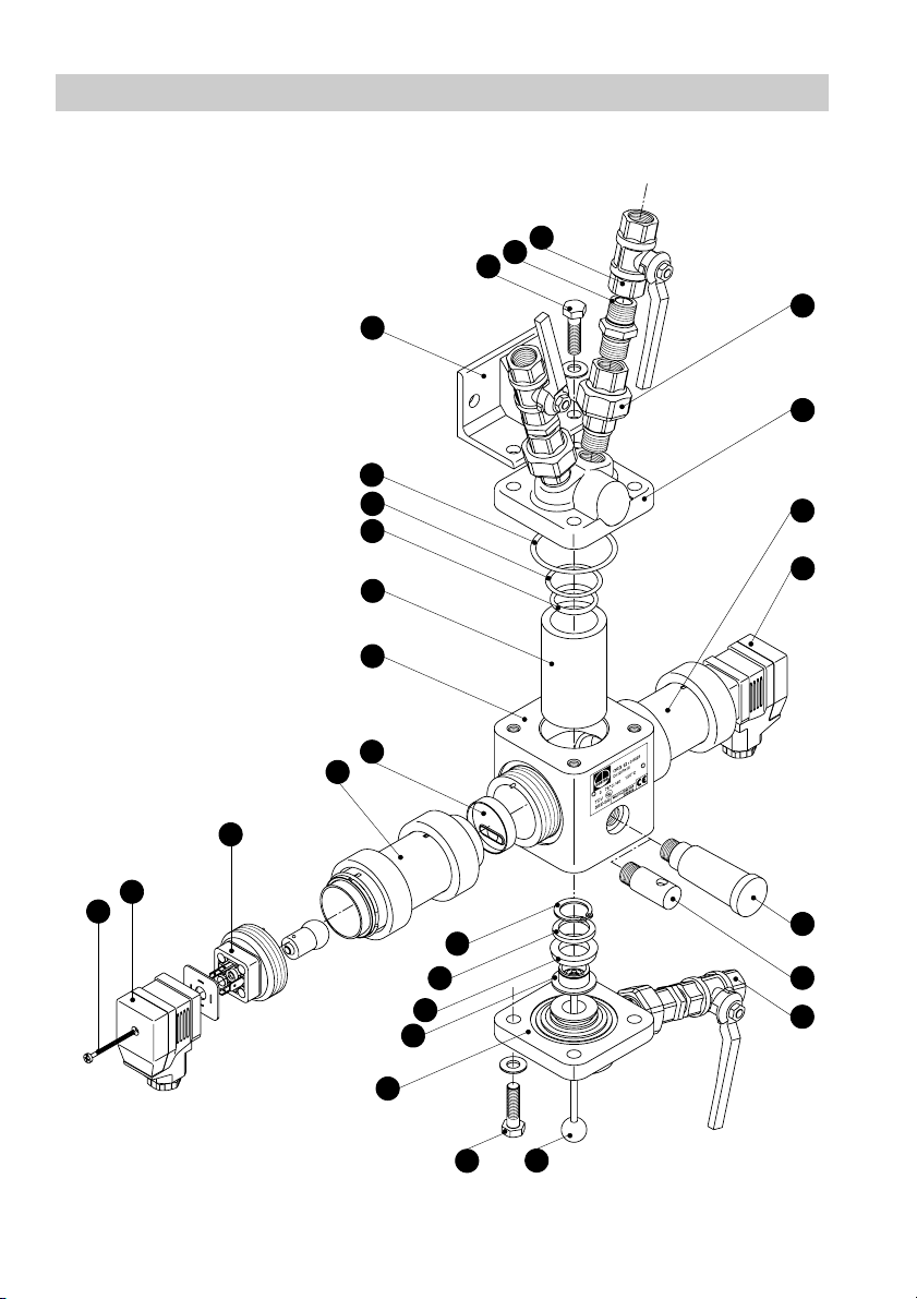
Component Parts
W
B
A
I
Z
Y
C
X
V
U
T
D
P
S
R
Q
P
O
N
M
L
K
J
H
I
2
G
F
E
Page 3

Key
A
Nipple with threaded ends
B
Ball valve ¾“ BSP (DIN ISO 228)
C
Upper cover flange
D
Light receiver with tube
E
Ball valve ¾“ BSP (DIN ISO 228) for purging
F
Vent nipple
G
Drying cartridge
H
Cleaning plunger
I
Hexagon-head screw M8x30 EN 24017
J
Lower flange
K
Support for cleaning ring
L
Cleaning ring (wiper)
M
Ring
N
Retaining ring 19x1.2
O
Screw
P
Connector for light emitter / light receiver
Q
Light emitter
R
Tube
S
Turbidity standard
T
Housing
U
Glass cylinder
O-ring 25x3
V
O-ring 30x2
W
X
O-ring 37x2
Mounting bracket
Y
Z
Screwed union
3
Page 4

Contents
Page
Important Notes
Usage for the intended purpose.......................................................................................6
Safety note.......................................................................................................................6
Warning............................................................................................................................7
Explanatary Notes
Scope of supply ...............................................................................................................8
Application .......................................................................................................................8
Function ...........................................................................................................................9
Technical data................................................................................................................10
Installation
Measuring sensor ORG 12, ORG 22 .............................................................................13
Measuring transducer ORT 6.........................................................................................17
Wiring
Measuring sensor ORG 12, ORG 22 .............................................................................18
Measuring transducer ORT 6.........................................................................................18
Tools ..............................................................................................................................19
Wiring diagram ORG 12, ORG 22, ORT 6.....................................................................19
Wiring diagram ORG 12, ORG 22, ORT 6 with three-way valve ...................................20
Functional Elements
Measuring transducer ....................................................................................................21
Commissioning Procedure
Factory settings..............................................................................................................22
Start-up procedure .........................................................................................................23
0% calibration ................................................................................................................23
100% calibration ............................................................................................................24
Oil / turbidity curves .......................................................................................................25
Detection and indication of various contaminants..........................................................25
Adjusting limit value alarm 1 ..........................................................................................26
Adjusting limit value alarm 2 ..........................................................................................26
Adjusting time delay for alarm 1.....................................................................................27
Adjusting time delay for alarm 2.....................................................................................27
Setting decimal point......................................................................................................28
Establishing actual value output ....................................................................................28
4
Page 5

Contents
Page
Operation
Start ...............................................................................................................................29
Alarm 1 and 2 ................................................................................................................29
Maintenance
Functional check............................................................................................................30
Functional test of relays for alarm 1, alarm 2 and malfunction ......................................30
Malfunctions...................................................................................................................30
Error code – Indication...................................................................................................31
Error Code – Table ........................................................................................................31
Exchanging glass cylinder .............................................................................................33
Cleaning glass cylinder..................................................................................................34
Replacing cleaning plunger ...........................................................................................34
Replacing drying cartridge ............................................................................................. 34
Replacing glow lamp......................................................................................................35
Replacing fuse ...............................................................................................................35
Tools ..............................................................................................................................35
Spare parts ....................................................................................................................36
Annex
Declaration of conformity ............................................................................................... 37
Certificate of type approval ............................................................................................ 40
Type approval certificate................................................................................................44
Updates .........................................................................................................................45
5
Page 6

Important Notes
Usage for the intended purpose
Use oil & turbidity detector OR 52 only for monitoring transparent liquids to detect any
ingress of light-scattering and insoluble foreign matter.
Chemical and corrosive influences have to be taken into account and the equipment must
only be used within its rated pressure and temperature limits. Before installation and
operation make sure that the equipment is resistant to the medium in the operational
conditions that will exist.
Any type of use differing from the usage described above is considered as improper.
The resulting risk will have to be borne by the user alone. The manufacturer hereby
expressly rejects any claims for any resulting damage.
Safety note
The equipment must only be installed, removed, commissioned, operated and serviced
by qualified staff.
Qualified staff are those persons who - through adequate training in electrical
engineering, the use and application of safety equipment in accordance with regulations
concerning electrical systems and circuits, and first aid & accident prevention – have
achieved a recognised level of competence appropriate to the installation and
commissioning of this device.
For installation, removal, commissioning, operation and maintenance, every person
who works with the equipment must have read and understood the complete installation
manual. Furthermore, responsibilities must have been defined clearly and
unambiguously and must be adhered to.
Usage of the equipment for the intended purpose includes compliance with the rules and
notes in this installation manual for installation, removal, commissioning, operation and
maintenance.
The operating company must ensure that, whenever the equipment is being operated,
it is in perfect condition.
Working methods that jeopardise safety must not be used.
6
Page 7

Important Notes
Warning
Danger
If the measuring transducer and sensor are used in an inexpert or
improper manner by unqualified staff, they can cause danger to life and
limb for the user or for third parties, possibly resulting in death.
During operation, the sensor is under pressure. In this condition, screws,
nuts or bolts must not be slackened. Hot water or steam could flow out and
could cause severe scalding over the entire body.
The sensor might be hot during operation. If it is touched when in the
operational condition, severe burns are possible.
Any installation or removal work may only be performed when the
equipment is at zero pressure and has cooled down. When such work is
to be done, the pressure in the pipes upstream and downstream must
have been reduced to zero and the sensor must have cooled down
sufficiently.
The terminal strips of the measuring transducer are live during operation.
This presents the danger of electric shock. Cut off power supply before
opening the cover or mounting/removing the terminal strips.
It must be ensured that during the work the system section in which
pressure has been reduced to zero cannot be accidentally put back into
operation. The shut-off valves needed for this purpose must be separately
secured and marked. The connection to the energy supply must be
disconnected and must be secured to prevent it from being operated
accidentally. One or more warning notices, for example containing the text
"DO NOT SWITCH ON" must be displayed in a clearly visible manner at
each operating element.
continued
7
Page 8

Explanatary Notes
Scope of supply
1 Measuring transducer ORT6,
1 Measuring sensor ORG12 or ORG 22 (depending on order),
3Ball valves,
3 Screwed unions and nipples with threaded ends,
1 Vent nipple (screwed in ORG),
1 Turbidity standard 20ppm (supplied but not fitted),
1 Drying cartridge (supplied but not fitted),
1 Installation manual,
Type approval certificates (according to order)
Application
The oil & turbidity detector consists of the measuring sensor ORG 12 or ORG 22 and the
measuring transducer ORT 6 (operating and display unit). The type of measuring sensor
depends on the fluid to be used.
The oil & turbidity detector OR 52-5/-6 is used for monitoring transparent liquids to detect
any ingress of insoluble foreign matter. The equipment is mainly used for industrial
processes and in the foodstuff industry where high level of reliability and ease of
maintenance are required.
The equipment combination can be used for marine applications in order to monitor
microfiltering equipment in accordance with IMO (International Maritime Organization)
resolution MEPC.60(33) and EC directive 96/98/eec (MED) as 15 ppm oil content alarm.
In steam boiler plants condensate and feedwater can be monitored for oil and grease
contamination (according to TRD 604 sheet 1 paragraph 2.1.1 with 3/5 ppm). In addition,
the oil & turbidity detector is well suited for raw water monitoring and water treatment
(sand filters, demineralization plants, reverse-osmosis plants) as well as waste-water
monitoring.
The OR 52 is also used in breweries and the beverage industry (filtration, monitoring of wort,
quality assurance etc.) and in the salad oil production for monitoring filtering processes.
Note
When using the equipment as 15 ppm oil content alarm acc. to IMO please
take the following into consideration:
Microfilter installations usually consist of an oil/water separator followed by
a filter, the so-called coalescer. Gravity coalescer systems cannot split up
stable water/oil emulsions, which are formed with certain cold cleaning
agents and then accumulate in the bilge. We therefore recommend
suitable fast-separating cold cleaning agents which will not produce
stable water-oil emulsions.
8
Page 9
Explanatary Notes
continued
Function
The measuring sensor is a photometric measuring device consisting of a light source
(light emitter ) and a light receiver equipped with two photosensitive elements.
Q
D
A constant light beam passes through the transparent liquid. Insoluble foreign matter
scatters the light, which is then measured using the 15° forward light scattering method.
The light intensity is transformed into an electric current which will be used by the
measuring transducer to determine the concentration of foreign matter. The actual
turbidity value is continuously compared with the adjusted setpoint and the result will be
indicated visually and - if required - acoustically.
The measuring transducer is the operating and indicating unit for signal evaluation and
the control of the measuring sensor. It serves as visual display unit for the measuring
results and the adjustment of the measuring equipment, indicating the actual value,
tripping the limit alarms ALARM 1 and ALARM 2 and releasing messages in the event of
a malfunction in the measuring sensor. The measuring transducer is designed for setting
and indicating the limit values.
ORT 6
ppm
cal
OIL
sec
0
ALARM
12
P
E
Test
ORG 12/22
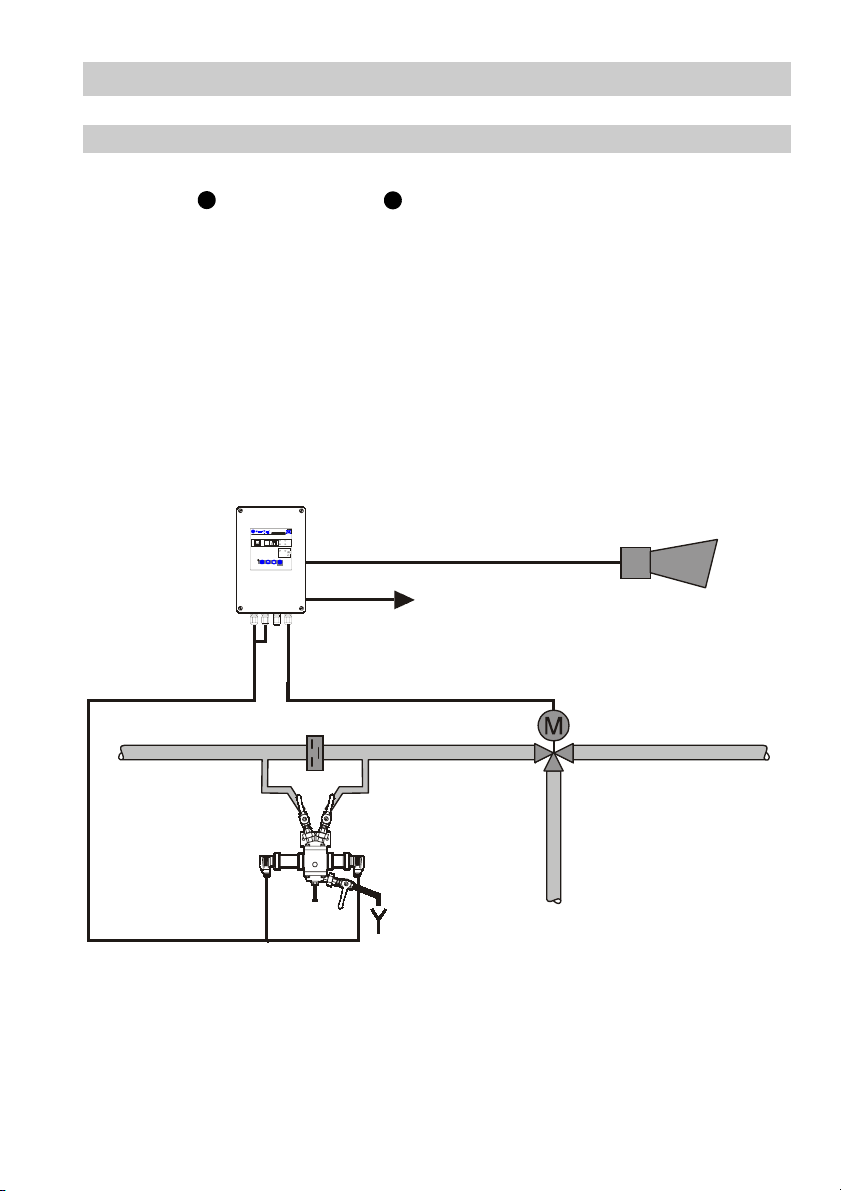
Fig.1
Typical application of an oil & turbidity detector type OR 52-5/-6
9
Page 10

Explanatary Notes
Technical Data
Measuring sensor ORG 12, ORG 22
continued
Nominal pressure PN 10 bar
Nominal size DN 10, screwed “ ¤§8 BSP to DIN ISO 228
Flowrate 0.5– 50 l/ min
1)
Pressure drop
Corrosive resistance Water, condensate, beverages, etc.
Max. pH value of fluids
Fluid temperature range
Approx. weight 6.8 kg
Housing 0.6025 galvanized 0.6025 galvanized
Cover 0.6025 galvanized 1.4580
Wetted parts 0.6025 galvanized 1.4580
Ball valves Brass 58 1.4436
Screwed unions Steel 1.4571
Glass cylinder Duran 50 Duran 50
Gaskets Silicone Silicone
Cleaning disc EPDM EPDM
2)
0–60 °C
(with drying cartridge)
Materials ORG12 ORG22
g (145 psi g)
5 mbar
10.5
60– 120 °C
(with vent nipple)
Light emitter
Light receiver
1)
At a flowrate of 2 l/min and V-shaped flow through the sensor with a pipe length of 1 m
Glow lamp 12V / 10W BA 15 s
Protection IP 65
2 silicon-type photo-electric cells
Protection IP 65
(DN 10) and 4 bends, ζ=6.1.
2)
A pH value above 10.5 can lead to wear of the glass, depending on the temperature.
3)
Vent nipple screwed in measuring transducer as standard.
F
10
Page 11
Explanatary Notes
continued
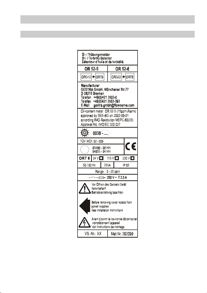
Technical Data
Name plate
contiuned
GL
11
Page 12
Explanatary Notes
continued
Technical Data
continued
Measuring Transducer ORT 6
Inputs Directly transmitted light (D), scattered light (S)
1 voltage output for light emitter ,
Q
1– 12V pulse-amplitude modulated
3 volt-free change-over contacts
Outputs
(alarm 1 + 2 and malfunction),
Contact material AgNi 0.15
Max. contact rating for switching voltages 24V AC / DC,
115V and 230V AC. Resistive / inductive 4 A
1 current output 0/4 – 20 mA, max. load 500 ohm
Measuring range 0– 25 ppm
Actual value output
Adjustment range
Limit value alarm 1 and 2
0/4 mA 0ppm, 20 mA 25ppm
Adjustable between 0 and 15ppm
Other ranges on request
4 membrane keys,
8 LEDs for indicating operating modes and dimensions,
Indicators and adjustors
1 three-digit seven-segment display for actual value,
limit value and fault indication,
3 LEDs for monitoring system voltages
Adjustment range
Time delay alarm 1 and 2
0 to 20 sec.
Other ranges on request
230V + 10 / - 15%, 50 – 60 Hz
Mains voltage
115V + 10 / - 15%, 50 – 60 Hz (optional)
24 V + 10 / -15%, 50–60 Hz (optional)
Power consuption 25 VA
Thermal fuse M 0.2A 5x 20 at 230 V
Fuse
Thermal fuse M 0.4A 5x 20 at 115 V
Thermal fuse M 1.0A 5x20 at 24 V
Housing Field case for wall installation
Housing material Die-cast aluminium
Protection IP 65 (DIN EN 60529)
Admissible ambient
temperature
0–55
°C
Approx. weight 3.6 kg
12
Page 13

Installation
Measuring Sensor ORG 12, ORG 22
It is highly advisable to have the installation work done by qualified staff in the manner
described by these installation instructions. The manufacturer will not accept liability for
damage resulting from improper installation.
The measuring transducer is designed for wall mounting and should be installed close
to the measuring sensor.
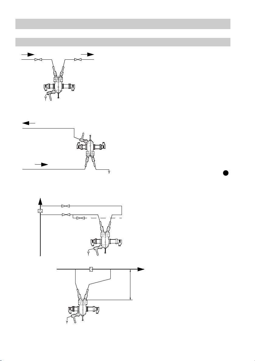
Install the measuring sensor and lines in accordance with the examples given in
figs. 2 to 7.
Provide a throttling point – e. g. a non-return valve (GESTRA type RK 86) in the main line.
Mount the measuring sensor in a bypass at a lower level than the main line so that any
gas bubbles and flash steam can pass through the main line instead of the sensor. Tap
main line at the side from the bottom to prevent air and dirt particles from flowing into the
bypass.
If the fluid temperature is above the max. ambient temperature:
Screw in vent nipple .
If the fluid temperature is below the ambient temperature:
Remove the plastic lid from the drying cartridge (blue colour) and screw in the drying
cartridge .
G
If the fluid temperature is very high:
Provide a non-insulated pipe upstream of ORG 12/ORG 22 which will allow the fluid to
cool down to 120 °C when reaching the sensor.
In the presence of large amounts of gas:
Tapping point must be at the bottom of the line – use a welding pocket in accordance with
DIN 2618 (see page 14 fig. 5).
If the condensate can be/is highly contaminated:
Ensure downward flow of the fluid through the glass cylinder (glass cylinder may be
scratched), for installation see page 14 fig. 3.
If this does not help and/or a lot of flash steam builds up ahead of the measuring sensor
fit a separator upstream of the equipment (see page 15, fig. 6).
Important
F
G
U
Avoid flashing, outgassing and the presence of air due to a pressure drop
upstream of the measuring sensor.
The additional connection of the cover flange must be reserved for the
C
inlet of either wash water or calibration fluid.
13
Page 14
Installation
continued
Measuring Sensor ORG 12, ORG 22
Inlet Outlet
Cleaning device V-shaped
Fig.2
flow through sensor,
automatic deaeration
Outlet
Cleaning device
Inlet
Fig.3
continued
Sensor installed in a sample line,
e. g. water treatment, beer
filtering, permeate downstream
of reverse osmosis.
Installation of sensor when the
condensate contains suspended
solids. If the sensor is installed in
acc. with figs. 4 – 6, solids could
deposit on the cleaning device
and scratch the glass cylinder .
U
Sensor installed in a bypass of a
product line with upward flow.
Fig.4
Fig.5
14
*)
500
≥
H
Sensor installed below a product
line carrying a slight amount of
gas, e. g. sufficiently sized
condensate line (flashing)
downstream of steam traps.
*) Tap product line at the side
(angle of 45°) from the bottom to
prevent air and dirt from flowing
into the bypass.
Page 15
Installation
DN>inl
continued
Measuring Sensor ORG 12, ORG 22
Flash steam
Separator
DN100-300
250
≥
H
Condensate
Downward flow
of sample if
condensate is very
contaminated
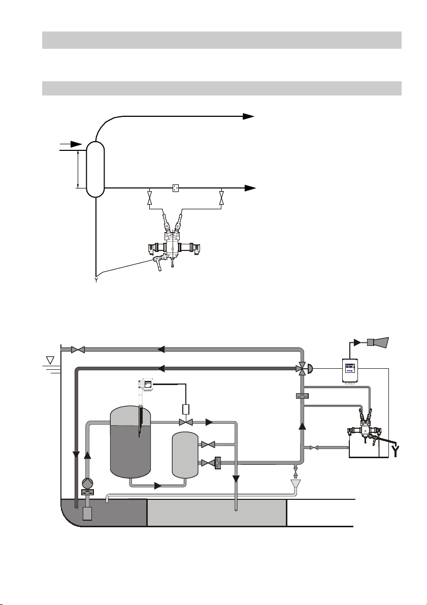
Fig.6
NRGS 16-1
continued
et
Installation of sensor in a
condensate line with large
amount of flash steam
ppm
cal
OIL
sec
0
ALARM
12
P E
Test
Fig.7
Schematic layout of oily water separation system for bilge water with the oil and turbidity
detector OR 52 as 15 ppm oil content alarm.
15
Page 16

Installation
continued
Measuring Sensor ORG 12, ORG 22
The cover flange and lower flange of the measuring sensor can be screwed turned
C J
continued
through 90°.
1. Screw in nipples with threaded ends , screwed unions and ball valves
supplied with the sensor into upper cover flange and lower flange or directly at
A Z B
C J
the inlet, outlet or purging points. Use teflon tape for sealing.
2. The screwed unions facilitate positioning of the ball valves so that the levers
Z B
can be arranged in one plane (front).
3. Fit the ORG 12/ORG 22 with the mounting bracket provided in an accessible
place. If the sensor is used on ships weld mounting bracket to its support.
Y
Y
4. For the inlet and outlet lines of the sensor use 12 mm OD Ermeto, 10 mm OD gas
pipe or suitable flexible tubes (for rinsing purposes).
5. Fit the light receiver in an accessible place. It can then be easily removed so that
visual inspection of the fluid is possible. The interchange of light emitter and light
receiver is possible after loosening the union nuts (inside) from the housing .
D T
When refitting, take care of correct fit of locating pins of the housing in the grooves
provided in light emitter and receiver . Tighten union nuts.
Be sure the equipment is damp proof – condensate on the outside of glass cylinder
D
Q
T
Q D
U
results in excessively high readings.
Fig.8
80
140
135
70
90
7
16
315
78
135
175200
5
40
375
Page 17

Installation
continued
Measuring Transducer ORT 6
Unscrew cover screws and swing up cover in order to gain access to the holes for
mounting the equipment. The distance between the holes is indicated on the back of the
case. Use suitable screws and wall plugs to mount the measuring transducer.
ppm
110
160
sec
ALARM
12
E
Test
cal
0
260
91
Fig.9
OIL
240
P
17
Page 18

Wiring
Measuring Sensor ORG 12, ORG 22
Before installing the measuring sensor cut off power supply!
Connect light emitter and receiver via connector .
1. Wire light emitter with a screened two-core cable
Q D P
Q
(do NOT connect screen),
e. g. LIYIC 2x0.75 mm², max. length 50 m).
2. Wire light receiver with screened four-core cable
D
(do NOT connect screen),
e. g. LIYIC 4x0.5 mm², max. length 50 m).
Measuring Transducer ORT 6
1. Unscrew lid screws and open lid.
2. Remove all three-pole terminal strips and pull connecting cables through
cable glands.
3. Mark connecting cables: "Mains", "Alarm 1" and "Alarm 2".
4. Strip off approx. 40 mm of cable insulation coating and remove approx. 5 mm
of conductor end insulation.
5. Connect terminal strips in accordance with wiring diagram and
connect
screens.
6. Connect PE with earthing screw in case.
7. Re-insert terminal strips.
8. Seal cable glands by tightening screws. Fit plug supplied with equipment to
seal unused cable glands.
9. Close lid and tighten lid screws.
10. Mount disconnecting device (disconnecting switch).
Attention
18
To protect the output contacts fuse circuits with 2.5 A (anti-surge).
Provide connected contactors and actuators with RC combinations
(in accordance with manufacturers' specifications) in order to suppress
interference.
Make sure that the disconnecting switch is easily accessible and in the
close proximity of the equipment (EN 61010-1).
Mark respective switch as disconnecting device for the measuring
transducer.
Page 19

Wiring
Tools
Screwdriver for cross-recess screws, size 1 and 2
Screwdriver for slotted screws, size 2.5, completely insulated to VDE 0680
Conductor end sleeve pliers
Insulation stripper
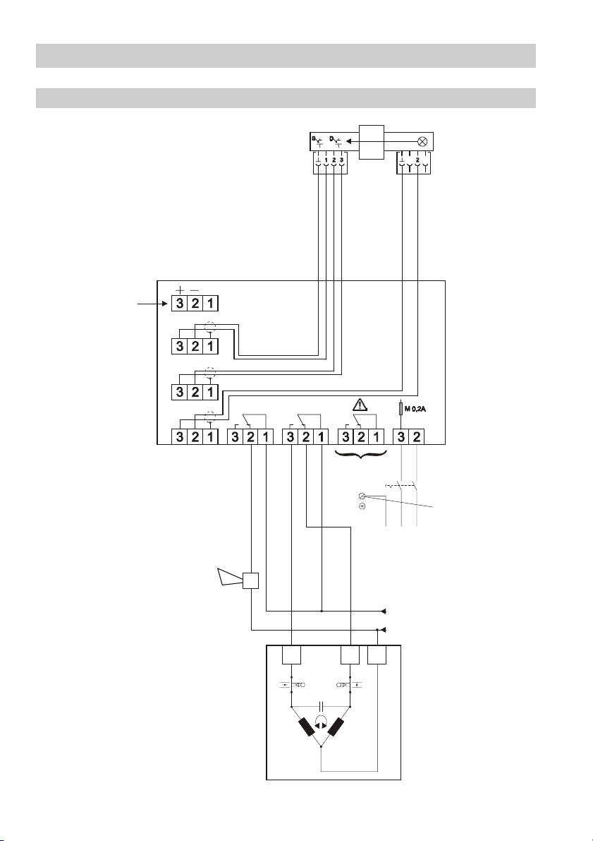
Wiring Diagram ORG 12, ORG 22, ORT 6
0/4–20mA
R≤500
continued
Measuring sensor ORG...
Measuring transducer ORT 6
Ω
Fig.10
S
D
Alarm2 Alarm1
L
Malfunction
Earthing screw
in housing
LN
Disconnecting
switch
PE L N
19
Page 20
Wiring
Wiring Diagram ORG 12, ORG 22, ORT 6 with three-way valve
continued
0/4–20mA
Ω
R≤500
Measuring sensor ORG...
Measuring transducer ORT 6
S
D
L
Valve OPEN: Fluid flowing
through
Valve CLOSED: Fluid is
discharged or
retained
Fig.11
20
Alarm2 Alarm 1
A
Malfunction
PE L N
Z
LN
Disconnecting
switch
Earthing screw
in housing
L
N
Page 21

Functional Elements
Measuring Transducer
Seven-
Unit LED
segment
display
OIL
ppm
sec
cal
0
Calibration LED
ALARM
12
Malfunction LED
(yellow)
Yellow P-LED
P
E
Test
The push buttons have the following functions:
P
= Program
= Increase
= Decrease
E
= Enter/Test mode
Partial view of base plate Partial view of front plate
L4
LEDdisplay
Operating
voltage
1
= + 5V
LED1
R16
2K7
L
LED2
LED3
2
= +12V
L
R17
R18
3
= Lamp
L
6K8
6K8
Code switch 7 for
decimal point
ON = with decimal point
OFF = without decimal point
P10
DHL-016- S100-11
Wire link 2 for actual
value output
with wire link: 0-20mA
without wire link: 4-20mA
10uH
L3
10uH
L2
10uH
L1
10uH
S5
1
on
2
34
5
678910
SDIX-10-XS
JP2
JP1
Factory setting: with wire link 1
P1
21
Page 22

Commissioning Procedure
Factory set default values
The measuring transducer features the following factory settings:
Limit value: Alarm 1: 3 ppm
Limit value: Alarm 2: 5 ppm
Delay of response: Alarm 1: 1 sec.
Delay of response: Alarm 2: 1 sec.
Actual value output: wire link 2 established = 0 - 20 mA
Seven-segment display without decimal point
Warning
The terminal strips of the measuring transducer are live during operation.
This presents the risk of electric shock.
Cut off power supply before opening the housing lid!
Before commissioning rinse the measuring sensor. Do not use caustic
agents for flushing unless the use of such agents is explicitly permitted by
the manufacturer.
22
Note
Adjust two different limit values if you want to use for instance alarm
contact 1 for a first alarm and alarm contact 2 for the main alarm.
For condensate and bilge water monitoring alarm contact 1 can then be
used to control a three-way valve, which will discharge the unusable
condensate if the level of turbidity is too high (alarm caused by ingress of
oil or start-up protection). Alarm contact 2 will trigger the main alarm / shutdown.
Valves with single-phase A.C. motor, max. power rating 50 VA (see wiring
diagram on page 20, fig. 11) can be connected directly. If a three-phase
actuator is used fit a reversing contactor in between. Pneumatically
operated valves can be controlled via solenoid valves.
Page 23

Commissioning Procedure
continued
First Commissioning
1. Switch on measuring transducer
(disconnecting switch).
2. Rinse measuring transducer ORG 12/22 for at
least 15 minutes and operate cleaning device
H
if necessary.
3. Make sure that the ORG 12/22 is completely free of
OIL
ppm
cal
sec
0
ALARM
12
air. For visual inspection undo union nuts (inside) and
remove light receiver . When screwing the light
receiver in again make sure that the locating pin
D
P
E
Test
fits exactly in the corresponding groove at the front
collar of the light receiver .
D
0% Calibration
Use tap water (with low fluid temperature) or oil-free condensate as turbidity zero.
1. Press until yellow P-LED lights up.
P
2. Use to change the LED display until the
calibration LED 0 lights up. The calibration value
(digits) saved last will be indicated.
3. Press , the yellow P-LED and the 7-segment
P
display are flashing.
4. Press , the 0 % value is saved as basic turbidity.
E
The P-LED and the 7-segment display are illuminated.
If the basic turbidity is too high an error message
OIL
P
ppm
cal
sec
0
ALARM
12
E
Test
will pop up.
5. Press , the equipment returns to normal operation, 0 ppm is indicated and the LED
E
for ppm is illuminated.
To cancel press twice, the yellow P-LED will light up again.
P
23
Page 24

Commissioning Procedure
100% Calibration
continued
Fit turbidity standard 20 ppm supplied with the equipment to the light emitter .
Unscrew union nut (inside) from tube and remove light emitter from housing of
the sightglass. Place turbidity standard on black tube so that the screen fitted in
the standard is exactly congruent with the screen of the tube . Screw in light emitter
Q T R
, making sure that the locating pin of the housing fits into the groove of the tube .
S R
S R
R Q T
S R
Tighten union nuts (inside).
Make sure that the liquid used for the calibration of the zero point stays in the glass
cylinder.
Further adjustments of the measuring transducer:
1. Press , the yellow P-LED lights up.
2. Press to change the LED display until the
3. Press , the yellow P-LED and the 7-segment display
P
calibration LED cal lights up. The calibration value
(digits) saved last will be indicated.
P
ppm
OIL
cal
sec
0
ALARM
12
are flashing.
4. Press , the 100 % value is saved. The P-LED and
E
P
E
Test
the 7-segment display are illuminated.
5. Press , the equipment returns to normal operation, 20 ppm is indicated and the LED
E
for ppm is illuminated.
To cancel press twice, the yellow P-LED will light up again.
P
Remove turbidity standard from measuring transducer and store carefully. Make sure that
it cannot be scratched.
24
Page 25

Commissioning Procedure
continued
Oil / Turbidity Curves
A light beam shines through the liquid and any foreign matter which is not dissolved scatters the beam. The scattered light intensity increases in proportion to the concentration
of suspended particles, the degree of turbidity depending on:
size of the particles (degree of emulsification)
shape and composition of the particles
optical properties of the particles
In the case of oils, fats and greases the degree of emulsification is a decisive factor.
Different suspended particles in the fluid
Indication [ppm]
2
25
345
20
15
10
5
2 4 6 8 10 12 14 16 18 20
Concentration [µl/l] = [ppm]
1
Fuel oil EL, 15°C, coarse emulsification Xylene, 80 °C, fine emulsification
2
Fuel oil EL, 15°C, fine emulsification Red-berry juice, concentrated
3 9
Fuel oil EL, 80°C, fine emulsification Black-berry juice, concentrated
4
Engine oil (medium), 15
fine emulsification
5
Vegetable oil, 15°C fine emulsification Turbine oil T68, gear oil M 68
6
Xylene, 20°C, fine emulsification
°C,
7
8
10
Skimmed milk, fat content 0.1% referred
to fat concentration
11
11
1
10
8
6
9
7
25
Page 26

Commissioning Procedure
Adjusting Limit Alarm 1
continued
1. Press , the yellow P-LED lights up.
P
2. Use to change the LED display until LED Alarm 1
and LED ppm light up. The value saved last is shown.
3. Press , the yellow P-LED and the second digit of the
P
7-segment display are flashing.
4. Use to change the digit, press to save the
E
OIL
ppm
cal
sec
0
ALARM
12
setting and move to the third digit. The third digit is
now flashing.
5. Use to change the digit, press to save the
E
P
E
Test
setting. The P-LED and the 7-segment display are
illuminated. A limit value of max. 15 ppm can be adjusted.
6. Press , the equipment returns to normal operation, the actual value is indicated and
E
the LED ppm is illuminated.
Adjusting Limit Alarm 2
1. Press , the yellow P-LED lights up.
P
2. Use to change the LED display until LED Alarm 2
and LED ppm light up. The value saved last is shown.
3. Press , the yellow P-LED and the second digit of the
P
7-segment display are flashing.
4. Use to change the digit, press to save the
E
OIL
ppm
cal
sec
0
ALARM
12
setting and move to the third digit. The third digit is now
flashing.
5. Use to change the digit, press to save the
E
P
E
Test
settings. The P-LED and the 7-segment display are
illuminated. A limit value of max. 15 ppm can be adjusted.
6. Press , the equipment returns to normal operation, the actual value is indicated and
E
the LED ppm is illuminated.
26
Page 27

Commissioning Procedure
Adjusting time delay for alarm 1
continued
1. Press , the yellow P-LED lights up.
P
2. Use to change the LED display until LED Alarm 1
and LED ppm light up. The value saved last is shown.
3. Press , the yellow P-LED and the second digit of the
P
7-segment display are flashing.
4. Use to change the digit, press to save the
E
OIL
ppm
cal
sec
0
ALARM
12
setting and move to the third digit. The third digit is
now flashing.
5. Use to change the digit, press to save the
E
P
E
Test
setting. The yellow P-LED and the 7-segment display
are illuminated. A max. time delay of 20 sec. can be adjusted.
6. Press , the equipment returns to normal operation, the actual value is indicated and
E
the LED ppm is illuminated.
Adjusting time delay for alarm 2
1. Press , the yellow P-LED lights up.
P
2. Use to change the LED display until LED Alarm 2
and LED ppm light up. The value saved last is shown.
3. Press , the yellow P-LED and the second digit of the
P
7-segment display are flashing.
4. Use to change the digit, press to save the
E
OIL
ppm
cal
sec
0
ALARM
12
setting and move to the third digit. The third digit is
now flashing.
5. Use to change the digit, press to save the
E
P
E
Test
setting. The yellow P-LED and the 7-segment display
are illuminated. A max. time delay of 20 sec. can be adjusted.
6. Press , the equipment returns to normal operation, the actual value is indicated and
E
the LED ppm is illuminated.
27
Page 28

Commissioning Procedure
continued
Indicating decimal point
The 7-segment display can show a decimal point.
This setting does not have any effect on the adjusted limit
values and time delays.
Cut off power supply!
OIL
Decimal point
ppm
sec
cal
0
Open housing lid of the measuring transducer and set code switch 7 on lid plate to ON.
Setting actual value output
The actual value output can be changed from 0–20 mA to 4–20 mA.
Cut off power supply!
Open the housing lid and remove wire link 2 from the lid plate.
Wire link 2 set: actual value output 0–20 mA
Wire link 2 removed: actual value output 4–20 mA
Danger
The terminal strips of the measuring transducer are live during operation.
This presents the risk of severe injuries due to electric shock. Cut off
power supply before opening the housing lid.
28
Page 29

Operation
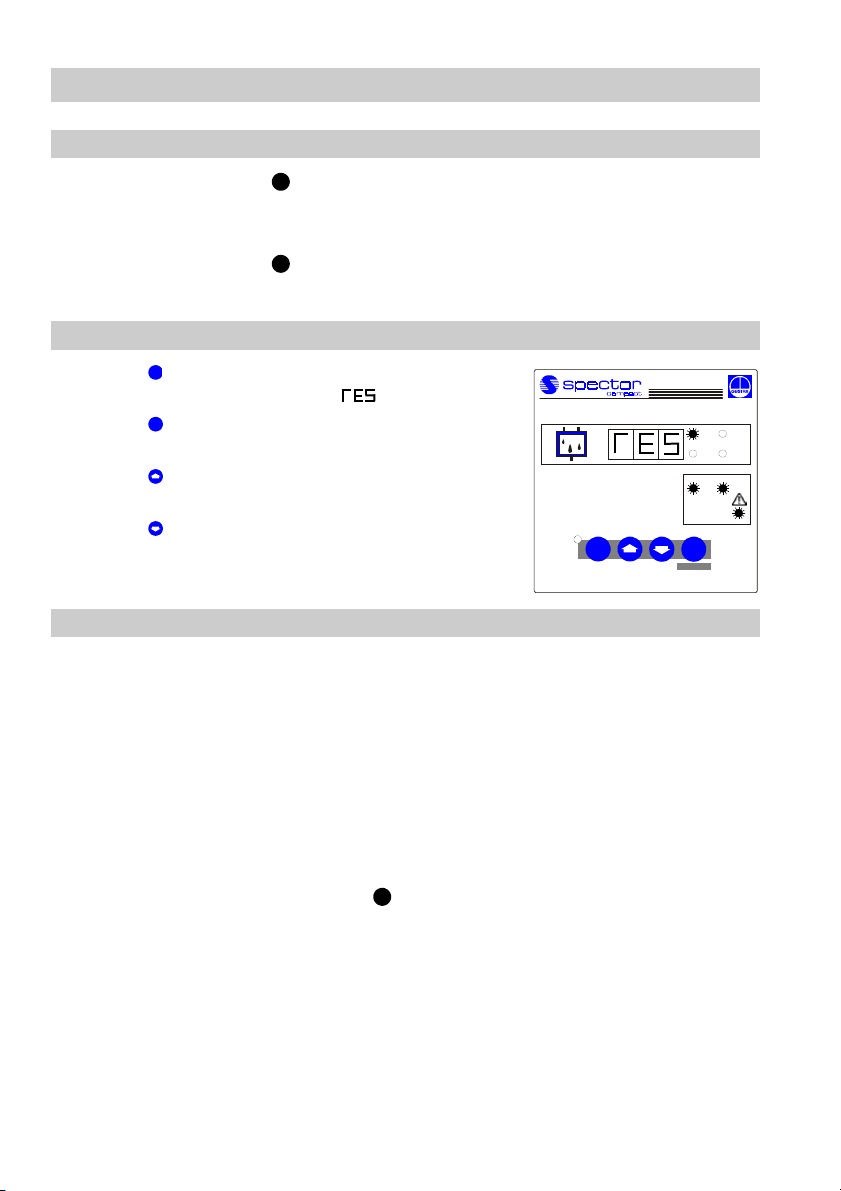
Start
Apply power.
The 7-segment display shows briefly the version number
of the software.
Then the indicator counts until the actual value is
reached.
The LED ppm is illuminated.
Alarm 1 and 2
When the limit value for alarm 1 or 2 is exceeded the
adjusted time delay is activated. The LED alarm 1 or
LED alarm 2 is flashing.
After the time delay has elapsed LED alarm 1 or LED
alarm 2 will light up.
The relay contact for alarm 1 or 2 opens.
Note
When the limit values are exceeded the measuring transducer will not
interlock automatically. If the installation requires a lockout function, the
latter must be implemented in the sequence circuit (burner protection
circuit). This circuit must comply with the requirements of the DIN VDE
0116 regulations.
ppm
OIL
OIL
cal
sec
0
ALARM
12
ppm
cal
sec
0
ALARM
12
29
Page 30
Maintenance
Functional Test
1. Push cleaning device slowly into mid-position to simulate a malfunction.
H
2. The LED "Malfunction" lights up and the relay contact "Malfunction" opens.
First error code E 03 is indicated and then error code E 08.
3. Push cleaning device back to its initial position.
H
The equipment must return to normal operation.
Functional Test Relay Alarm 1, Alarm 2 and Malfunction
1. Press briefly to activate the test mode for 10 sec.
E
The 7-segment display shows .
2. Press . While the button is held down LED Alarm 1
P
lights up and relay contact Alarm 1 opens.
OIL
3. Press . While the button is held down LED Alarm 2
lights up and relay contact Alarm 2 opens.
4. Press . While the button is held down the LED
Malfunction lights up and the relay contact Malfunction
P
opens.
Malfunctions
1. The measuring transducer does not work – no function, no display
Fault: Equipment fuse defective.
Remedy: Replace equipment fuse with a new one. Check power supply.
Fault: Power failure. Not all three green LEDs on the base plate are
illuminated at the same time.
Remedy: Check power supply or replace measuring transducer.
2. Measured value increases steadily by 1 ppm per day (or slower) –
ingress of foreign matter can be ruled out
Fault: Growing contamination of glass cylinder.
Remedy: Operate cleaning device more often.
H
ppm
cal
sec
0
ALARM
12
E
Test
30
Page 31

Maintenance
continued
Indication of Error Code
In the event of a malfunction the yellow LED Malfunction
lights up, the relay output Malfunction opens and the
7-segment display indicates the error code.
The raising of an alarm is not effected by a malfunction.
ppm
OIL
cal
sec
0
ALARM
12
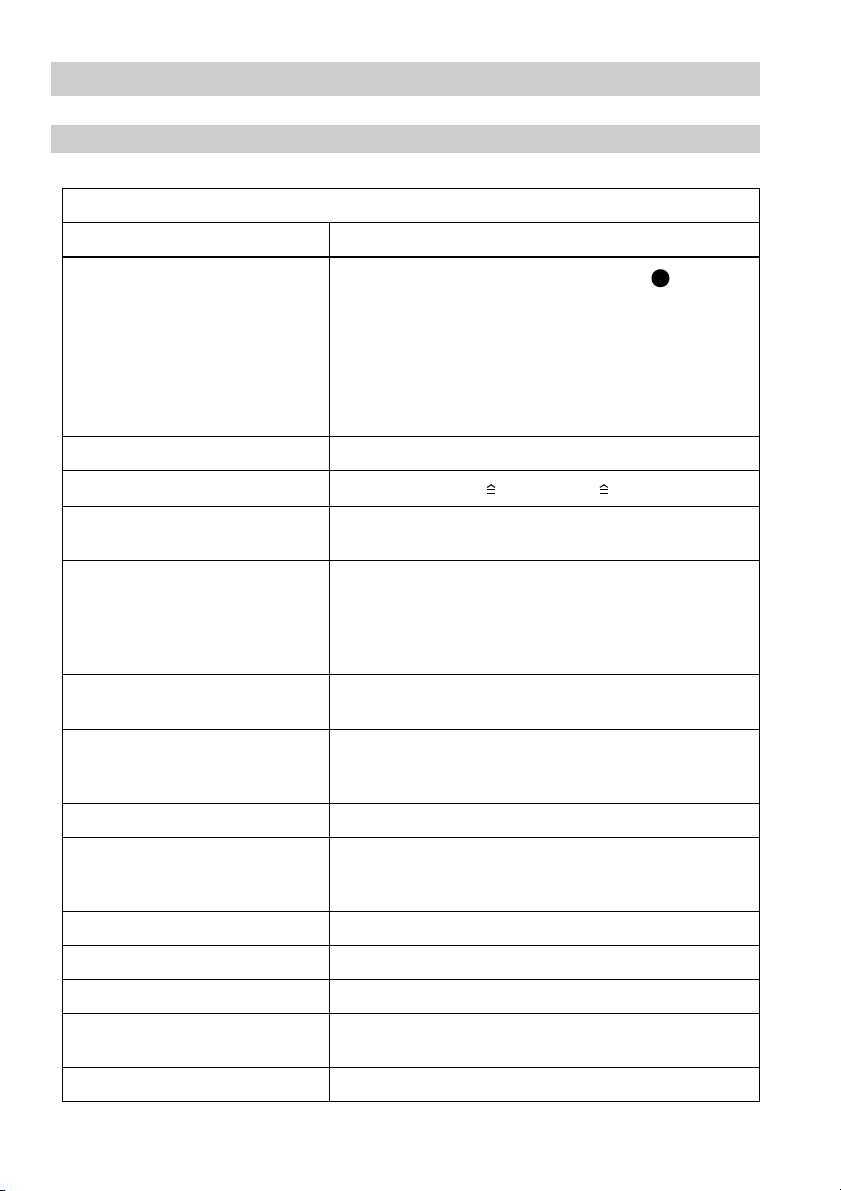
Error Code Table
Error code
E01
P
E
Test
Possible reason Remedy
Q
Glow lamp in light emitter
contaminated
Glass cylinder contaminated Clean or replace glass cylinder
U U
Turbidity of fluid too high
Replace glow lamp
Provide mechanical cleaning stage
ahead of equipment
Operating voltage too low Check supply voltage
Cleaning device not in its initial
H H
position
Ingress of solids
Return cleaning device to its
initial position
Provide mechanical cleaning stage
ahead of equipment
31
Page 32

Maintenance
continued
Error Code Table
Error code
E03
Error code
E05
continued
Possible reason Remedy
Glow lamp in light emitter
defective. A frequent occurrence
of this problem indicates heat
accumulation in light emitter
(despite fluid temp. > 60 °C
Q
Replace glow lamp. Remove
Q
drying cartridge and install
vent nipple
G
F
drying cartridge mounted)
Cable connection to light
Q
emitter interrupted
Cleaning device not in its
H H
initial position
Ingress of solids
Check connecting cables
Return cleaning device to its
initial position
Provide mechanical cleaning stage
ahead of equipment
Possible reason Remedy
Basic turbidity > 10 ppm
Glass cylinder scratched
U
(ingress of solids)
Glass cylinder contaminated Clean or replace glass cylinder
U U
Provide mechanical cleaning stage
ahead of equipment
Replace glass cylinder .
U
Install sensor acc. to installation
example fig. 3
Error code
E06
32
Ingress of solids
Presence of gas or steam
bubbles (flashing)
Provide mechanical cleaning stage
ahead of equipment
Throttle outlet
Possible reason Remedy
Light receiver defective or
incorrectly connected.
D D
Replace light receiver or check
connecting cables
Measuring transducer defective Replace measuring transducer
Page 33

Maintenance
continued
Error Code Table
Error code
E08
continued
Possible reason Remedy
Glow lamp or light emitter
Q
defective.
Connection to light receiver /
Q
emitter interrupted
Cleaning device not in its initial
H H
D
position
Ingress of solids
Replace glow lamp
Check connecting cables
Return cleaning device to its
initial position
Provide mechanical cleaning stage
ahead of equipment
Once the fault is eliminated the equipment will return to normal operation.
Replacing Glass Cylinder
1. Close ball valves for inlet and outlet. Open ball valve for rinsing .
2. Slacken (but do not remove) the eight hexagon head screws . Insert the cleaning
device into the housing (for fitting pull out the cleaning device as shown on
H T
page 14, fig. 3), unscrew the four hexagon head screws on top and remove the
housing .
T
3. Pull out the cleaning device and remove the glass cylinder . If the equipment
has not been used for a longer period of time, the glass cylinder might be stuck
due to dirt accumulated on the upper cover flange .
4. Check whether housing , upper cover flange and lower flange are completely
dry inside. If not, dry housing with compressed air as any moisture remaining in
the housing would lead to the glass cylinder becoming covered with mist when
B E
I
I
H U
U
C
T C J
T
U
cold fluids are used and this would lead to faulty measurements.
5. Undo the four hexagon head screws at the bottom.
6. Take out the O-rings , clean seating surfaces and insert new
O-rings .
V W X
V W X
7. Hold new and dry glass cylinder at the rim and push it over the seat of the
upper cover flange .
8. Attach the housing to the upper cover flange using screws .
9. Insert the plunger of the cleaning device into the glass cylinder and screw
the lower flange to the housing .
10. Close ball valve for rinsing , open ball valves for inlet and outlet.
C
T C I
K H U
J T
E B
I
U
Check 0 % and 100 % settings of the measuring transducer.
33
Page 34

Maintenance
continued
Cleaning Glass Cylinder
1. Move ring of the cleaning device up and down. Note that dependent on the
L H
adjusted time delay Alarm 1 and/or Alarm 2 may be triggered off.
2. Move ring of the cleaning device back to its initial position (operating bar
L H
protrudes approx. 70 mm from the sightglass). If the glass cylinder is very
contaminated replace the wiping ring of the cleaning device .
Clean glass cylinder at regular intervals - at least once a week, dependent on the de-
U
gree of contamination of the fluid. Replace glass cylinder if it is strongly contaminated.
L H
U
Replacing Cleaning Plunger
1. Close ball valves for inlet and outlet. Open ball valve for rinsing .
2. Pull out cleaning device and unscrew the four hexagon head screws of the
lower flange . Remove lower flange with cleaning device .
B E
H I
J J H
3. Use screwdriver for bending open the inside serrations of the fixing disc and remove
the fixing disc.
4. Take out plunger and insert new plunger .
K K
5. Mount new fixing disc. Make sure that the serrations point in the opposite direction
of the plunger .
6. Remove O-rings from the lower flange, clean seating surfaces and insert
new O-rings .
7. Push plunger of the cleaning device into the glass cylinder and screw lower
flange firmly to housing .
8. Close ball valve for rinsing , open ball valves for inlet and outlet.
K
V W X
V W X
K H U
J T
E B
9. Check 0 % and 100 % settings of the measuring transducer.
Replacing Drying Cartridge
Replace drying cartridge when its content turns pink. Should this happen too often
G
check the following items for tightness;
O-rings at light emitter and receiver
Gaskets at connectors , front gaskets of glass cylinder
Cable glands at connectors of light emitter and receiver
Q H
P U
P Q D
34
Page 35

Maintenance
continued
Replacing Glow Lamp
1. Unscrew and remove union nut (outside) of tube of light emitter .
R Q
2. Replace glow lamp (12 V 10 W) with a new one.
3. Fit light emitter . Take care that the locating pin of the light emitter fits the groove
provided on the tube . Tighten union nut.
Q Q
R
4. Repeat calibration of zero point (0 %) and measuring range (100 %) at measuring
transducer.
Replacing Equipment Fuse
1. Open housing cover of the measuring transducer.
2. Turn fuse carrier to the left and take it off.
3. Replace equipment fuse with a new one:
Type (anti-surge) 0.2 A 5x20 at 230 V, (anti-surge) 0.4 A 5x20 at 115 V, (anti surge)
M 1.0 A 5x20 at 24 V.
4. Fit fuse carrier in place and turn it to the right. Close housing cover.
Warning
The terminal strip of the measuring transducer is live during operation.
This presents the danger of severe injuries due to electric shock.
Cut off power supply before opening the housing cover.
Tools
Spanner for hexagon head screws, A. F. 13
Screwdriver for slotted head screws, size 2.5
35
Page 36

Maintenance
continued
Spare Parts
A spare parts kit containing the following items is available on request:
Item
U
V
W
X
K
M
L
N
Designation Qty.
Glass cylinder 1
O-ring 25x 3 2
O-ring 30x 2 2
O-ring 37x 2 4
Glow lamp 2
For cleaning device
Plunger 1
Ring 1
Cleaning ring (wiper) 1
Retaining ring 19x 1.2 1
Fixing disc 1
36
Page 37

Annex
Declaration of Conformity
37
Page 38

Annex
continued
Declaration of Conformity
continued
38
Page 39

Annex
continued
Declaration of Conformity
continued
39
Page 40

Annex
Certificate of Type Approval
continued
40
Page 41
Annex
continued
Certificate of Type Approval
continued
41
Page 42

Annex
continued
Certificate of Type Approval
continued
42
Page 43

Annex
continued
Certificate of Type Approval
continued
43
Page 44

Annex
Type Approval Certificate
continued
44
Page 45

Annex
Updates
continued
Index
00 New installation manual 04-08-2003
Description Date
45
Page 46

46
Page 47

47
Page 48

GESTRA Gesellschaften • GESTRA Companies • Sociétés GESTRA • Sociedades Gestra • Società GESTRA
Vertretungen weltweit • Agencies all over the world • Représentations dans le monde entier • Representaciones en todo el mundo • Agenzie in tutto il mondo
Great Britain
Flowserve Flow Control (UK) Ltd.
Burrel Road, Haywards Heath
West Sussex RH 16 1TL
Tel. 00 44 14 44 / 31 44 00
Fax 00 44 14 44 / 31 45 40
E-mail: sales@flowserve.com
France
Flowserve Flow Control S.A.S.
10 Avenue du Centaure, BP 8263
F-95801 CERGY PONTOISE CEDEX
Tél. 0 03 31 / 34 43 26 60
Fax 0 03 31 / 34 43 26 87
E-mail: gnation@flowserve.com
España
GESTRA ESPAÑOLA S.A.
Luis Cabrera, 86-88
E-28002 Madrid
Tel. 00 34 91 / 5 152 032
Fax 00 34 91 / 4 136 747; 5 152 036
E-mail: gestra@gestra.es
Italia
Flowserve S.p.A.
Divisione Italgestra
Via Prealpi, 30 – 20032 Cormano (MI)
Tel. 00 39 02 / 66 32 51
Fax 00 39 02 / 66 32 55 60
E-mail: info@italgestra.it
Portugal
Flowserve Portuguesa, Lda.
Av. Dr. Antunes Guimarães, 1159
Porto 4100-082
Tel. 0 03 51 22 / 6 19 87 70
Fax 0 03 51 22 / 6 10 75 75
E-mail: gestra@gestra.pt
GESTRA
®
P.O.Box 10 54 60, D-28054 Bremen, Münchener Str. 77, D- 28215 Bremen
Telephone +49 (0) 421 35 03-0, Fax +49 (0) 421 35 03-393
E-Mail gestra.gmbh@flowserve.com, Internet www.gestra.de
An Unit of Flowserve Corporation
810731-01/903c · © 2003 GESTRA GmbH · Bremen · Printed in Germany
GmbH
 Loading...