

Page 1

OR 42
OR 52
Installation Instructions 810476-00
GESTRA Oil and Turbidity Detector
1
Page 2

OR 42, OR 52
N
∅ 6
1
2
5 4
6 7 8 9 10
3
220 V
231
P
∅ 6
121
151
95
O
N
19 17 15 13 11
18 16 14 12
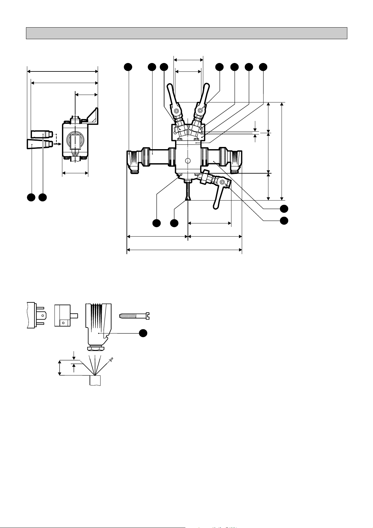
Fig. 1
2
310
220 V
P
7
180
230
110
O
Page 3
OR 42, OR 52
≈85
M L
Fig. 2
140
135
78
70
CBA D E F G
K J
80
135
175200
375
≈90≈125100
7
315
H
I
Fig. 3
A
5
40
3
Page 4
OR 42, OR 52
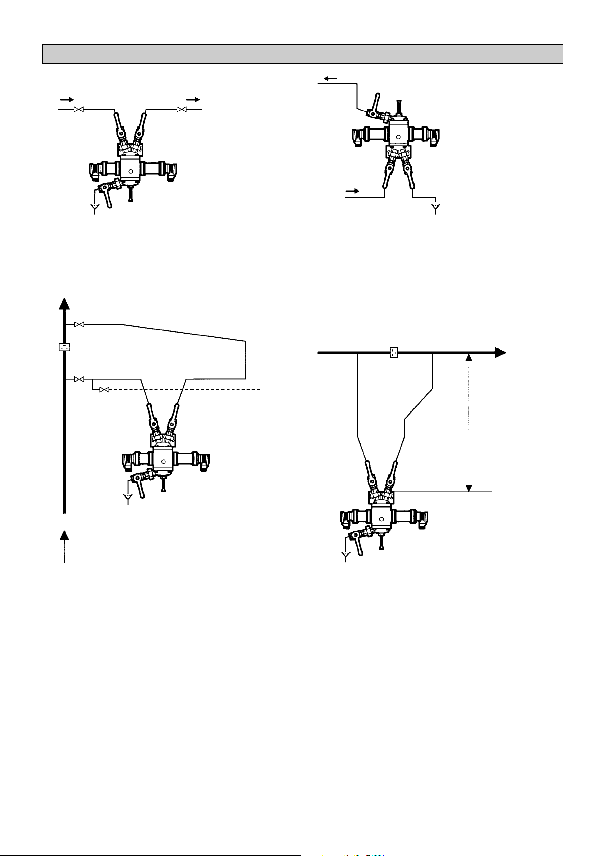
Fig. 4 Fig. 5
*)
H ≥ 500
Fig. 6 Fig. 7
*) T ap product line at the side (angle of 45°) from the bottom to pre vent air and dirt from flowing into the
bypass.
4
Page 5

OR 42, OR 52
DN 100-300
H ≥ 250
Fig. 8
Fig. 9
5
Page 6

OR 42, OR 52OR 42, OR 52
OR 42, OR 52
OR 42, OR 52OR 42, OR 52
Netz
Mains
Secteur
Red
Rete
Netz
Mains
Secteur
Red
Rete
0 – 20 mA
R ≤ 500Ω
Tv = 0
0 – 1 mA
R ≤ 120Ω
Fig. 10 Fig. 1 1
A
[ppm][TE/F]
25
20
15
10
5
2 4 6 8 10 12 14 16 18 20 2 4 6 8 10 12 14 16 18 20
4
5
3
2
[µl/l] = [ppm]
1
B
A
50
40
30
20
10
Fig. 12 Fig. 1 3
10
8
6
9
7
B
[µl/l] = [ppm]
6
Page 7

ENGLISH
Important Safety Note
Use oil and turbidity detector OR 42/OR 52
only for monitoring of transparent liquids to
detect any ingress of insoluble and
refracting foreign matter, for measuring of
turbidity and signal evaluation for indication
and recording as well as for tripping of
alarms, control valves etc.
The equipment must only be installed by
qualified staff.
Before installing the oil and turbidity detector
cut off power supply.
All repairs must be performed only by the
manufacturer. Misuse or any attempted
modification of the equipment will endanger
plant safety.
Warning
The terminal strip of the ORT4/ORT5 is live
during operation. This presents the danger
of electric shock. Cut off power supply
before opening the equipment or
undertaking any maintenance work
Purpose
The oil and turbidity detector OR 42/OR 52
consists of the sensor ORG 12/ORG 22
and the measuring transducer ORT 4/
ORT 5.
Application:
■
In steam boiler plants: Monitoring of
condensate returned to the boiler for oil
and grease contamination, in particular
for boilers operating without constant
supervision acc. to TRD 604 (2 detectors
are required for 72 h operation)
■
For raw-water monitoring and water
treatment (sand filters, demineralization
plants, reverse-osmosis plants)
■
For waste-water monitoring
■
In breweries and the beverage industry
(filtration, monitoring of wort, quality
assurance etc.)
■
For salad oil production: Monitoring of
filtering process
■
For marine applications: Monitoring of
filtering equipment in accordance with
IMO (International Maritime Organization)
resolution MEPC.60(33) – when certain
cold cleaning agents that split up easily
are used which cannot form stable water/
oil emulsions
Types
Turbidity Detector Transducer Sensor
OR 42/3 ORT 4 ORG 12
OR 42/4 ORT 4 ORG 22
OR 52/3 ORT 5 ORG 12
OR 52/4 ORT 5 ORG 22
Design
■
With three ball valves, three screwed
unions and screwed-in vent nipple
■
Drying cartridge and turbidity standard
20 ppm (OR 52: also turbidity standard
40 TU/F*) are also supplied
■
Spare parts kit separately available, see
“Spare Parts”
*) TU/F = turbidity units of Formazin suspension
Operation
The oil and turbidity detector measures the
intensity of the scattered light produced by
foreign matter that is not dissolved in transparent liquids and exposed to incident light,
with emulsified oils scattering incident light
mainly in the forward direction.
In the oil and turbidity detector the forward
scattered-light principle is applied which
provides a high sensitivity for emulsified
greases and oils and other organic matter.
Tec hnical Data ORG
Approvals
■ Feedwater monitoring
TÜV – approval no. 09-96-0132
■ Feedwater monitoring in marine
applications GL 94855-94 HH
Seeberufsgenossenschaft
GL-OG-94-352002
■ 15 ppm oil detector for bilge monitoring in
engine rooms
GL 85486-94 HH
Seeberufsgenossenschaft
320023
Nominal size
DN 10, connections
BSP to DIN ISO 228
Nominal pressure
PN 10
Flowrate
0.5 ... 50 l/min
3
/8"
Light emitter
At a flowrate of 2 l/min and V-shaped flow
through the sensor with a pipe length of 1 m
(DN 10 mm) and four bends: approx. 5 mbar
(ζ = 6.1)
Fluids
Water, condensate, drinks etc.
pH value
Up to 10.5 (a pH value of 11 and above will
lead to wear of the glass, depending on the
temperature)
Fluid temperature ranges
0 ... 60°C with drying cartridge
60 ... 120°C with vent nipple
Protection
IP 65
Max. ambient temperature
60°C
Materials ORG 12 ORG 22
Cover flange GG-25 1.4580
Wetted parts 0.6025 1.4580
galvanized
Ball valves Ms 58 1.4436
Screwed unions St 1.4571
Glass cylinder Duran 50 Duran 50
O-rings EPDM EPDM
Housing 0.6025 0.6025
galvanized galvanized
Cleaning disc EPDM EPDM
Light emitter
Glow lamp 12 V/10 W BA 15 s
cable connection via 4 pole connector
Light receiver
Two silicon photo-electric cells,
cable connection via 4 pole connector
Approx. weight
6.8 kg
Dimensions
See Fig. 2
Spare Parts
The spare parts kit for OR contains:
Designation Number
Glass cylinder 1
O-ring 25 x 3 2
O-ring 30 x 2 2
O ring 37 x 2 4
Glow lamp 2
For cleaning unit:
Cleaning plunger 1
Ring 1
Cleaning disc 1
Retaining ring 19 x 1.2 1
Fixing disc 1
7
Page 8

Tec hnical Data ORT
ORT 4 ORT 5
Wiring 3 cable glands with integral cable clamps PG 11, 3 cable glands with integral cable clamps PG 11,
Mains supply 230 V ± 10 %, 50/60 Hz 230 V ± 10 %, 50/60 Hz
Fuse Thermal fuse M 0.1 A Thermal fuse M 0.2 A
Power consumption 15 VA 25 VA
Measured quantity Turbidity Turbidity
Measuring range 0 – 25 ppm Range I: 0 – 50 TU/F*)
Lamp voltage for light emitter No-load voltage 14 V No-load voltage 14 V
Actual-value output 0 – 1 mA 0 – 20 mA (option 4 – 20 mA)
Output 1 volt-free relay contact 2 volt-free relay contact
Switchpoint Adjustable over complete measuring range Adjustable over complete measuring range
Delay of response 0 s with external wire linke, 10 s 0.5 – 15 min. adjustable, see name plate
Indicators and adjustors 1 LED
Protection IP 54 to DIN 40050 IP 65 to DIN 40050
Max. admissible ambient 0 – 55°C 0 – 55°C
temperature
Housing material Sheet steel, hammer enamel finish Die-cast aluminium, blue enamel finish
Weight 1.6 kg 5.4 kg
Dimensions See Fig. 1 See Fig. 1
*) TU/F = turbidity units of Formazin suspension, ppm = parts per million
screw-type terminals with wire guard, screw-type terminals with wire guard,
max. conductor size 1.5 mm² max. conductor size 1.5 mm²
115 V ± 10 %, 50/60 Hz (option) 115 V ± 10 %, 50/60 Hz (option)
124 V ± 10 %, 50/60 Hz (option) 124 V ± 10 %, 50/60 Hz (option)
Rated voltage see name plate Rated voltage see name plate
Measuring range see name plate Range II: 0 – 25 ppm*)
Measuring range see name plate
with light emitter connected: < 12 V AC, 10 W with light emitter connected: < 12 V AC, 10 W
load 0 ... 120 Ω load 0 ... 500 Ω
Max. contact rating with a switching Max. contact rating with a switching
voltage of 24/115/230 V AC: voltage of 24/115/230 V AC:
resistive 4 A, inductive 0.75 A at cos ϕ = 0.5 resistive 4 A, inductive 0.75 A at cos ϕ = 0.5
Max. contact rating with a switching Max. contact rating with a switching
voltage of 24 V DC: 4 A voltage of 24 V DC: 4 A
Life or relay: 10 x 10
6
switching cycles Life of relay: 10 x 106 switching cycles
Contact material: AgCdO 5 µ hard-gold plated Contact material: AgCdO 5 µ hard-gold plated
without wire link, see name plate
ALARM, 1 LED OPERATION, 1 LED ALARM (INSTANTANEOUS), 1 LED ALARM (DELAYED),
1 LED
MALFUNCTION, 1 potentiometer for switchpoint, 1 LED OPERATION, 1 LED MALFUNCTION,
2 potentiometers for adjustment 0/100 % 1 LED analogue display
RESOLUTION 3 %,
1 potentiometer for switchpoint,
2 potentiometers for adjustment 0/100 %,
1 potentiometer for adjustment of delay of response,
1 change-over switch for measuring range I/II,
1 change-over switch for switchpoint/measured value
Installation
ORG 12/ORG 22
Install and wire ORG 12/ORG 22 in
accordance with the examples given in
figures 4 to 9.
Mount ORG 12/ORG 22 in a bypass at a
lower level than the main line so that any air
and flash steam can pass through the main
line.
To ensure a flow through the bypass a
throttling point should be provided in the
main line, e. g. GESTRA non-return valve
type RK 66.
Tap product line at the side from the
bottom to prevent air and dirt from
flowing into the bypass.
Any pressure drop upstream of the sensor
which might lead to the release of gases or
to flashing must be avoided.
8
Screw in vent nipple when the fluid
L
temperature is above the max. ambient
temperature (Fig. 2).
When the fluid temperature is below the
ambient temperature remove the plastic lid
from the drying cartridge (blue colour)
M
and screw in the drying cartridge. (Fig. 2)
If the fluid temperature is very high provide
a non-insulated pipe upstream of ORG 12/
ORG 22 which will allow the fluid to cool
down to 120 °C when reaching the sensor.
The second inlet at the lid must be open
for the rinsing water or the calibrating fluid.
In the presence of large amounts of gas
the tapping point must be at the bottom of
the line – use a welding pocket in
accordance with DIN 2618 (Fig. 7, Pos.*)
In the case of very contaminated
condensate: downward flow of the fluid
through the glass cylinder
If the condensate contains suspended
solids (scratching of the glass) installation
as per Fig. 5 should be chosen. If this does
not help and/or a large amount of flash
steam escapes install a separator
upstream of the sensor (Fig. 8)
F K
1. Lid and base can be screwed
turned through 90°.
2. Screw in nipples , screwed unions
E D
and ball valves supplied with the
C
sensor (use teflon tape or hemp for
sealing).
3. They have to be fitted into the lid and
K
base or directly at the inlet, outlet or
F
purging point.
4. The screwed unions facilitate
positioning of the ball valves so that the
levers can be arranged in one plane
(front).
Page 9

5. Fit the ORG 12/ORG 22 with the mounting
bracket provided in an accessible place.
If the sensor is used on ships weld
mounting bracket to its support.
6. Use 12 mm OD Ermeto (screwed
12 mm copper tubing or 10 mm OD gas
pipe (screwed
3
/8") for the inlet and outlet
3
/8") or
lines of the sensor. For rinsing pur poses
suitable flexible tubes should be provided.
7. Fit the light receiver in an accessible
H
place. It can then be easily removed, so
that visual inspection of the fluid is
possible. The interchange of light emitter
and light receiver is possible after
loosening the union nuts (inside). When
refitting, take care of correct fit of locating
pins in the grooves provided in light
emitter and receiver. Tighten union nuts.
Take care of tightness against moisture –
condensate on the outside of glass
cylinder results in too high measured
values.
ORT 4, ORT 5
Wall mounting within reasonable distance
from ORG 12/ORG 22.
Installation dimensions see Fig. 1. The
spacing between the holes is indicated on
the back of the housing. ORT 5: Unscrew lid
N
screw and remove lid to gain access to
the holes for mounting.
Wiring
ORT 4, ORT 5
1. ORT 4: Turn screw through 90° and
open lid, see wiring diagram on operating
panel.
ORT 5: Unscrew lid screw and open
lid, see wiring diagram on the inside of the
lid.
2. Pull cable through cable glands .
3. Connect conductors according to wiring
diagram (Fig. 10/11). Connect control
circuits to output contacts and fuse
separately with T 2.5 A.
4. Tighten cable gland to provide sealing.
5. Seal unused cable glands.
6. Replace lid, tighten screw , in doing so
pay attention to correct position of lid
gasket.or to flashing must be avoided.
ORG 12, ORG 22
Connect light emitter and receiver in
accordance with Fig. 3.
1. Connect light emitter. A two-core cable
(conductor size 1.5 mm²) for distances up
to 90 m can be used.
2. Connect light reciver. A screened fourcore cable, e. g. 2x2x0.8 mm or 4 x 0.5
mm² is required. Max. length 90 m.
N
N
O
O
N
Attention
■ To protect the switching contacts fuse
circuit with T 2.5 A or according to TRD
regulations (1.0 A for 72 hrs operation).
■ Connect screen only to terminal 12
(ORT 4) / terminal 6 (ORT 5).
■ The screen must not make contact with
any metal part of the installation.
■ When switching off inductive loads,
voltage spikes are produced that may
impair the operation of control and
measuring systems. Inductive loads
should be provided with commercial arc
suppressor RC combinations, e. g.
0.1 µF/100 Ω.o flashing must be avoided.
Commissioning
1. Switch on ORT 4/ORT 5.
2. Rinse ORG 12/ORG 22 for at least 15
minutes. Operate cleaning device if
J
required.
3. Check visually whether ORG 12/ORG 22
is completely vented. For this purpose
unscrew union nuts (inside) and remove
light receiver . When screwing in light
H
receiver ensure that the locating pin fits
into the groove provided on the front
collar of the light receiver.
4. Calibrate zero point (0 %) and measuring
range (100 %).
5. Adjust switchpoint.
6. Set time delay.
o flashing must be
avoided.
Calibration of Zero Point (0%)
Use tap water (in case of low fluid
temperature) or oil-free condensate as
turbidity zero.
ORT 4
1. Set switchpoint adjustor to 0 ppm.
2. Turn measuring range adjustor (100 %)
2
to medium position.
3. Turn zero point adjustor (0 %) until the
red LED extinguishes and the green
LED just lights up. If the green LED
5
4 4
does not light up clean the pipework.
ORT 5
1. Set change-over switch for measuring
2. Loosen stop screws / of 0 %
3. Loosen stop screw of time delay
4. Turn 0 % adjustor until the LED
5. Slightly tighten stop screws .
19
range to position I and selector switch
10
in position “measured value”.
adjustor and 100 % adjustor by half a
turn.
adjustor and turn the latter against the
13
left stop. Set 100 % adjustor on
graduation 4.5.
analogue display is just no longer
illuminated. If zero indication cannot be
obtained: clean pipework. If this does not
help: add remaining turbidity value when
calibrating measuring range (100 %).
1
3
16 18
14
15
17
6
18
Calibration of Measuring Range (1 00%)
Fitting of turbidity standard
1. Choose turbidity standard supplied with
the equipment:
ORT 4: 20 ppm
ORT 5: Measuring range I: 40 TU/F*)
Measuring range II: 20 ppm
*) TU/F = Turbiditiy units of Formazin
TU/F = suspension
2. Unscrew union nuts (inside) and remove
light emitter from sightglass. Place
B
turbidity standard on black tube so that
the screen fitted in the standard exactly
fits the diaphragm in the tube.
3. Screw in light emitter ensuring that the
locating pin on the sightglass fits into the
groove of the light emitter. Tighten union
nut (inside).
4. Make sure that the liquid used for the
calibration of the zero point stays in the
glass cylinder.
4. Make the following adjustments on the
ORT 4/ORT 5:
ORT 4
6. Set switchpoint adjustor to 20 ppm.
7. Turn 100 % adjustor just until the red
5
LED lights up.
8. Remove turbidity standard and store
carefully. Make sure that it cannot be
scratched.
1
2
ORT 5
6. Set change-over switch for measuring
7. Loosen stop screw of 100 % adjustor
8. Slightly tighten stop screws .
9. Remove turbiditiy standard and store
19
range to position I or II dependent on
the turbidity standard used. Set selector
10
switch to “Measured value”.
16
and turn the adjustor until the LED
analogue display indicates 40 TU/F or
15
6
20 ppm. If required, add remaining
turbidity value – see “Calibration of Zero
Point (0 %)”, item 4.
16
carefully. Make sure that it cannot be
scratched.
Adjustment of Switchpoint
An alarm is given when the actual value
exceeds the adjusted switchpoint.
Tool: Screwdriver
ORT 4
1. Set switchpoint adjustor to the desired
ppm value.
ORT 5
1. Set change-over switch for measuring
2. Set selector switch measured value/
3. Loosen stop screw of switchpoint
4. Turn adjustor until the LED analogue
5. Slightly tighten stop screw.
6. Set selector switch measured value/
19
range to position I (top scale) or
position II (bottom scale) dependent on
the desired switchpoint.
switchpoint to “Switchpoint”.
10
adjustor.
display indicates the turbidity value
11
desired as switchpoint.
switchpoint back to “Measured value”.
10
1
12
9
Page 10

Adjustment of Time Delay
ORT 4
A time-delayed alarm is given when the
switchpoint is exceeded. The time delay
prevents temporary variations in the
turbidity of the fluid from raising an alarm.
Time delay set at our factory: 10 s
To eliminate the time delay provide an exter-
nal wire link between terminals 19 and 20.
ORT 5
The ORT 5 features two alarm channels:
■ Channel A 1 operates without delay:
The corresponding relay contact can be
used for triggering a three way valve,
so that contaminated fluid is immediately
discharged from the system.
■ Channel A 2 operates with a delay which
is adjustable between 0.5 and 15 minutes
for start-up and purging purposes, when
at the beginning the turbidity is very high
without representing a case of alarm.
Tool: Screwdriver
1. Loosen stop screw of adjustor and
set required time delay.
2. Slightly tighten stop screw .
14 13
14
Functional T est
1. After applying mains voltage the green
2. Operate cleaning device . The green
3. Set cleaning device back to its initial
4 9
LED / must be permanently
illuminated (Fig. 1). ORT 5: If a three-way
valve is connected the fluid must flow
straight through.
4 9
LED / must extinguish.
ORT 4: The red LED must light up.
ORT 5: The red LED and after the set
time delay the red LED must light up. If
J
5
8
7
a three-way valve is connected it must
open to discharge the fluid.
position. The red LEDs must extinguish.
J
Maintenance
Clean glass cylinder at regular intervals – at
least once a week, dependent on the
degree of contamination of the fluid.
Replace glass cylinder if it is strongly
contaminated.
st lightup.
ORT 5: The red LED and after the set
time delay the red LED must light up. If
a three-way valve is connected it must
open to discha
With fluids having a normal transparency the
service life of the glow lamp is more than
10 000 hrs. It is, however, recommended to
replace the glow lamp each time the glass
cylinder is being cleaned.
When the content of the drying cartridge
M
has assumed a pink colour it can no longer
absorb moisture and must be replaced.
If frequent replacing is necessary check
equipment for tightness:
■
O-rings on light emitter and receiver .
■
Cable entries on light emitter and
receiver .
■
Gaskets of terminal boxes , gaskets of
H
B H
B
A
glass cylinder, oil-seal rings.
Cleaning of Glass Cylinder
1. Move the disc of the cleaning device
up and down. Note that dependent on the
adjusted time delay a temporary alarm
may be given.
2. Move the disc of the cleaning device
back to its initial position (operating bar
protrudes approx. 70 mm from the
sightglass). In case of strong
contamination of glass cylinder replace
plunger of the cleaning device.
J
J
Exchange of Glass Cylinder
1. Close ball valves for inlet and outlet.
Open ball valve for rinsing .
2. Loosen hexagon head screws and
remove base with cleaning device.
3. Remove glass cylinder from below.
4. Check whether housing, lid and base are
completely dry inside. If not, dry with
compressed air. In case of cold fluids,
any moisture remaining in the housing
would lead to the glass cylinder becoming
covered with mist and therefore faulty
measurements.
5. Loosen screws and withdraw housing
from lid .
F
6. Remove O-rings, clean sealing surfaces
and insert new O-rings.
7. Replace housing and fix lid with
G
screws .
8. Hold new and dry glass cylinder at the
rim and push into housing from below until
it is located in the upper O-ring.
9. Insert plunger of the cleaning device
into glass cylinder. Screw base to
housing by using hexagon screws.
D
I
K
G
F
J
K
10.Close ball valve for rinsing , open ball
D
valves for inlet and outlet.
I
11. Check zero-point adjustment and
calibration of the ORT 4/ORT 5.
Replacement of Glow Lamp
1. Unscrew union nut (outside) of the lid
of the light emitter and remove lid.
2. Exchange glow lamp.
3. Replace lid of the light emitter. Take care
that locating pin fits the groove provided
on the light emitter. Tighten union nut.
4. Repeat calibration of zero point (0%) and
measuring range (100 %).
A
Replacement of Mains Fuse
1. Turn fuse carrier to the left and take off
(Fig. 1).
2. Exchange fuse. Required types:
230 V M 0.1 A 5 x 20 M 0.2 A 5 x 20
115 V M 0.2 A 5 x 20 M 0.4 A 5 x 20
3. Replace fuse carrier and turn to the
right.
P
ORT 4 ORT 5
P
Replacement of Cleaning Device
T ools: Spanner
Screwdriver
1. Close ball valves for inlet and outlet.
Open ball valve for rinsing .
2. Loosen hexagon head screws and
remove base with cleaning device.
3. Use screwdriver for bending open the
inside serrations of the fixing disc and
remove fixing disc.
4. Withdraw plunger and insert new plunger.
5. Mount new fixing disc. Make sure that the
serrations do not point towards the
plunger.
6. Remove O-rings from base, clean sealing
surfaces and insert new O-rings.
7. Push plunger of the cleaning device
into glass cylinder. Screw base to
housing by using hexagon screws.
8. Close ball valve for rinsing , open ball
D
valves for inlet and outlet.
9. Check zero-point adjustment and
calibration of the ORT 4/ORT 5.
D
I
K
J
K
I
10
Page 11

Fault Finding
Fault Finding
Fault Possible reason Remedy
No lighting up of LEDs Mains fuse defective Replace mains fuse
Lamp “Malfuncion” on Basic turbidity of fluid too high Refer to “Basic turbidity too high” in this table
Glass cylinder highly contaminated Clean or replace glass cylinder
Glass cylinder scratched (solids in condensate) Replace glass cylinder. Install ORG 12/ORG 22
Glow lamp in light emitter defective Replace glow lamp
Cable leading to light emitter defective Check cable
Calibration of zero point Cable leading to light receiver defective Measuring of lamp voltage < 12 V only possible
(0 %) not possible if lamp intact
Glass cylinder highly contaminated Clean or replace glass cylinder
Glass cylinder scratched (solids in condensate) Replace glass cylinder. Install ORG 12/ORG 22
Glass cylinder covered with condensation Check gaskets of terminal boxes and glass cylinder,
Drying cartridge assumed pink colour ? Replace drying cartridge
Extremely eccentric position of glow lamp filament Insert glow lamp with central filament position
Basic turbidity of fluid too high Add indicated value of 100 % calibration to turbidity
No indication of measured Cable leading to light receiver defective Check cable
value
Basic turbidity too high Presence of gas or steam bubbles (flashing) Throttle outlet (indication must drop)
Basic turbidity specific of fluid To measure basic turbidity: Repeat calibration of 0 %
Measured value rises If ingress of foreign matter can be excluded, Operate cleaning device more frequently
continually 1 ppm/day growing contamination of glass cylinder
Glow lamp often defective Heat accumulation in light emitter since fluid Remove drying cartridge and install vent nipple
temperature > 60 °C and drying cartridge mounted
acc. to mounting suggestion Fig. 5
acc. to mounting suggestion Fig. 5
O-rings of light emitter and light receiver
standard value
and 100% with distilled water
If faults occur that are not listed above,
please contact our subsidiary or agency
in your country.
11
Page 12

GESTRA Gesellschaften · GESTRA Companies · Sociétés GESTRA · Sociedades Gestra · Società GESTRA
Vertretungen weltweit · Agencies all over the world · Représentations dans le monde entier · Representaciones en todo el mundo · Agenzie in tutto il mondo
®
GESTRA GmbH
Postfach 10 54 60
D-28054 Bremen
Münchener Strasse 77
D-28215 Bremen
Tel. + 49 (0) 421 35 03 -0
Fax +49 (0) 421 35 03- 393
Internet www.gestra.de
E-mail
gestra.gmbh@flowserve.com
A Unit of Flowserve Corporation
12
810476-00/999c · ©1996 GESTRA GmbH · Bremen · Printed in Germany
España
GESTRA ESPAÑOLA S.A.
Luis Cabrera, 86-88
E-28002 Madrid
Tel. (091) 5152 032
Fax (091) 4 136 747; (091) 5152 036
France
Flowserve Flow Control S.A.S.
10 Avenue du Centaure, BP 8263
F-95801 CERGY PONTOISE
Tél. (01) 34.43.26.60
Fax (01) 34.43.26.87
Great Britain
Flowserve Flow Control UK
Burrel Road, Haywards Heath
West Sussex RH 16 1TL
Tel.00 44 14 44 / 31 44 00
Fax00 44 14 44 / 31 45 40
Italia
Flowserve S.p.A.
Divisione Italgestra
Via Prealpi, 30 - 20032 Cormano (Mi)
Tel.00 39 02 / 66 32 51
Fax00 39 02 / 61 51 863
Polska
GESTRA POLONIA Spolka z o.o.
Ul. Schuberta 104
PL-80-172 Gdansk
Tel. (058) 306 10 02
Fax (058) 306 1003
Portugal
Flowserve Portuguesa, Lda.
Av. Dr. Antunes Guimarães, 1159
P-4100 Porto
Tel.0 03 51 22 / 6 19 87 70
Fax0 03 51 22 / 6 10 75 75
 Loading...