

Page 1

Limitorque
®
DDC-100 Master Station II
Installation and Operation Manual
FCD LMAIM5001-00
(Replaces 435-11000)
Limitorque Actuation Systems
Page 2

2 DDC-100 Master Station II Installation and Operation Manual FCD LMAIM5001-00
Flow Control Division
Limitorque Actuation Systems
Master Station
Installation and Operation Manual
©2004 Copyright Flowserve Corporation. All rights reserved.
Printed in the United States of America.
Disclaimer
No part of this book shall be reproduced, stored in a retrieval system, or transmitted by any means,
electronic, mechanical, photocopying, recording, or otherwise without the written permission from
Flowserve. While every precaution has been taken in the preparation of the book, the publisher assumes
no responsibility for errors or omissions. Neither is any liability assumed for damages resulting from the
use of the information contained herein.
This document is proprietary information of Flowserve furnished for customer use ONLY. No other uses
are authorized without written permission of Flowserve.
Flowserve reserves the right to make changes, without notice, to this document and the products it
describes. Flowserve shall not be liable for technical or editorial errors or omissions made herein; nor for
incidental or consequential damages resulting from the furnishing, performance or use of this document.
This manual contains information that is correct to the best of Flowserve’s knowledge. It is intended to be
a guide and should not be considered as a sole source of technical instruction, replacing good technical
judgment, since all possible situations cannot be anticipated. If there is any doubt as to exact installation,
configuration, and/or use, please contact Flowserve at 1-800-225-6989.
The choice of system components is the responsibility of the buyer, and how they are used cannot be the
liability of Flowserve Corporation. However, Flowserve’s sales team and application engineers are always
available to assist you in making your decision.
MS-DOS
®
is a registered trademark of Microsoft Corporation.
IBM-PC
®
is a registered trademark of International Business Machines Corporation.
Belden
®
is a registered trademark of Belden, a division of Cooper Industries, Inc.
Page 3

FCD LMAIM5001-00 DDC-100 Master Station II Installation and Operation Manual 3
Flow Control Division
Limitorque Actuation Systems
Page 4

4 DDC-100 Master Station II Installation and Operation Manual FCD LMAIM5001-00
Flow Control Division
Limitorque Actuation Systems
Page 5

FCD LMAIM5001-00 DDC-100 Master Station II Installation and Operation Manual 5
Flow Control Division
Limitorque Actuation Systems
1 Introduction
1.1 Overview
The Limitorque Master Station II is a revolutionary step forward in control technology. The device is
capable of controlling up to 250 actuators, offers full redundancy, provides easy-to-use HMI interfaces,
and allows for high-speed data-transfer via a Modbus DCS port or Modbus Ethernet port. In addition, a
built-in web server can be used for monitoring network status from any remote station using TCP/IP. Web
server operation is covered in Section 18.
1.2 User Rights Overview
The Master Station requires users to login. Three user role levels are provided: View, Control, Configure.
Each role includes the rights of the lesser roles, i.e. Control includes View’s rights, and Configure includes
Control’s rights and View’s rights.
View: the user can view the network status and the activity log. No control or configuration functionality
is available.
Control: in addition to View’s rights, the user has the ability to control MOVs.
Configure: in addition to Control’s rights, the user has the ability to configure the Master Station and
the Network.
The default passwords for each role are:
View: 100
Control: 200
Configure: 300
These passwords can be changed by the Configure user. Changing passwords is discussed in Section 9.
Page 6
6 DDC-100 Master Station II Installation and Operation Manual FCD LMAIM5001-00
Flow Control Division
Limitorque Actuation Systems
1.3 Login
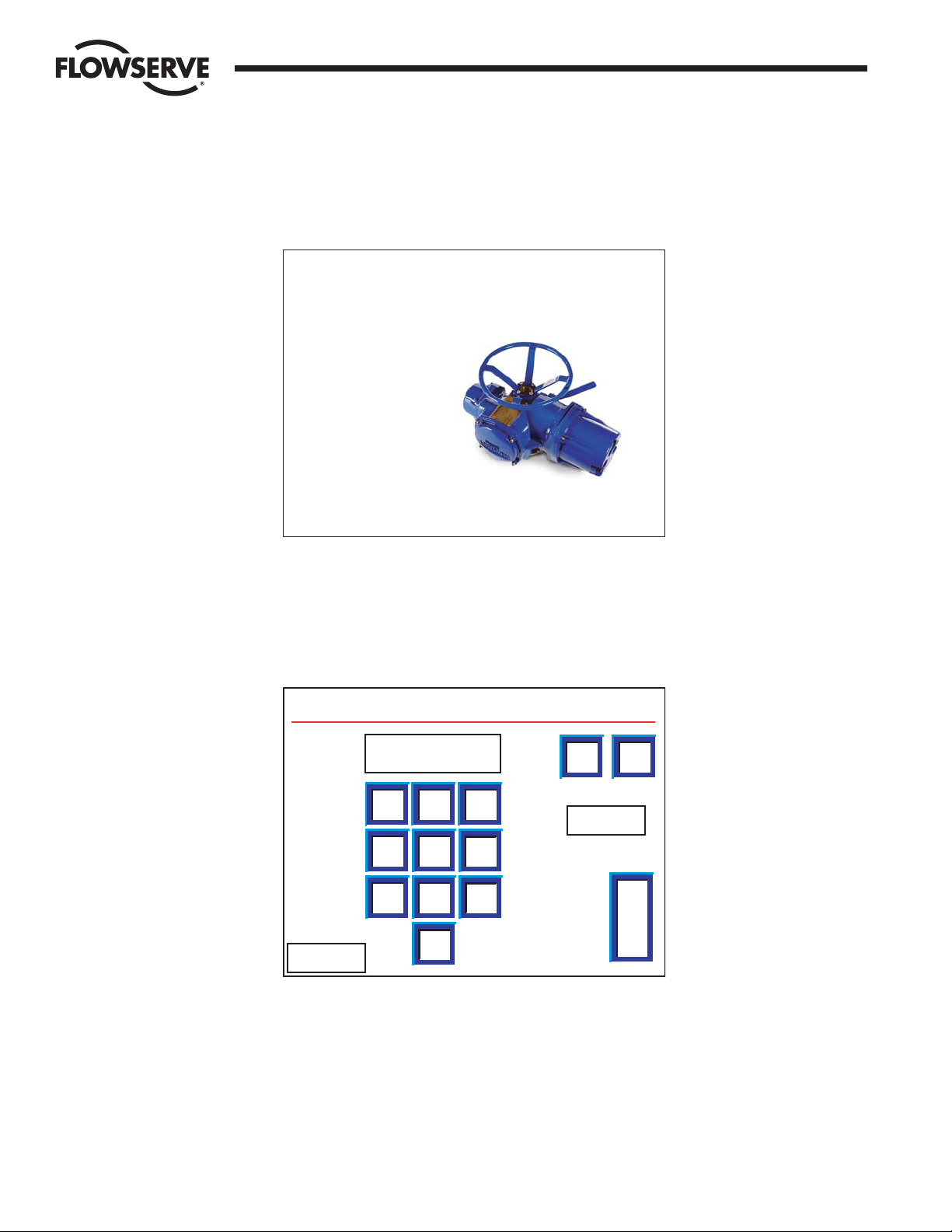
When the Master Station starts, it loads the default startup screen (Figure 1-1).
Figure 1-1: The Introduction screen
Touching any part of the screen will load the login screen (Figure 1-2).
Note: If the screen is blank and the green LED is illuminated, touch the display to exit the screen
saver mode.
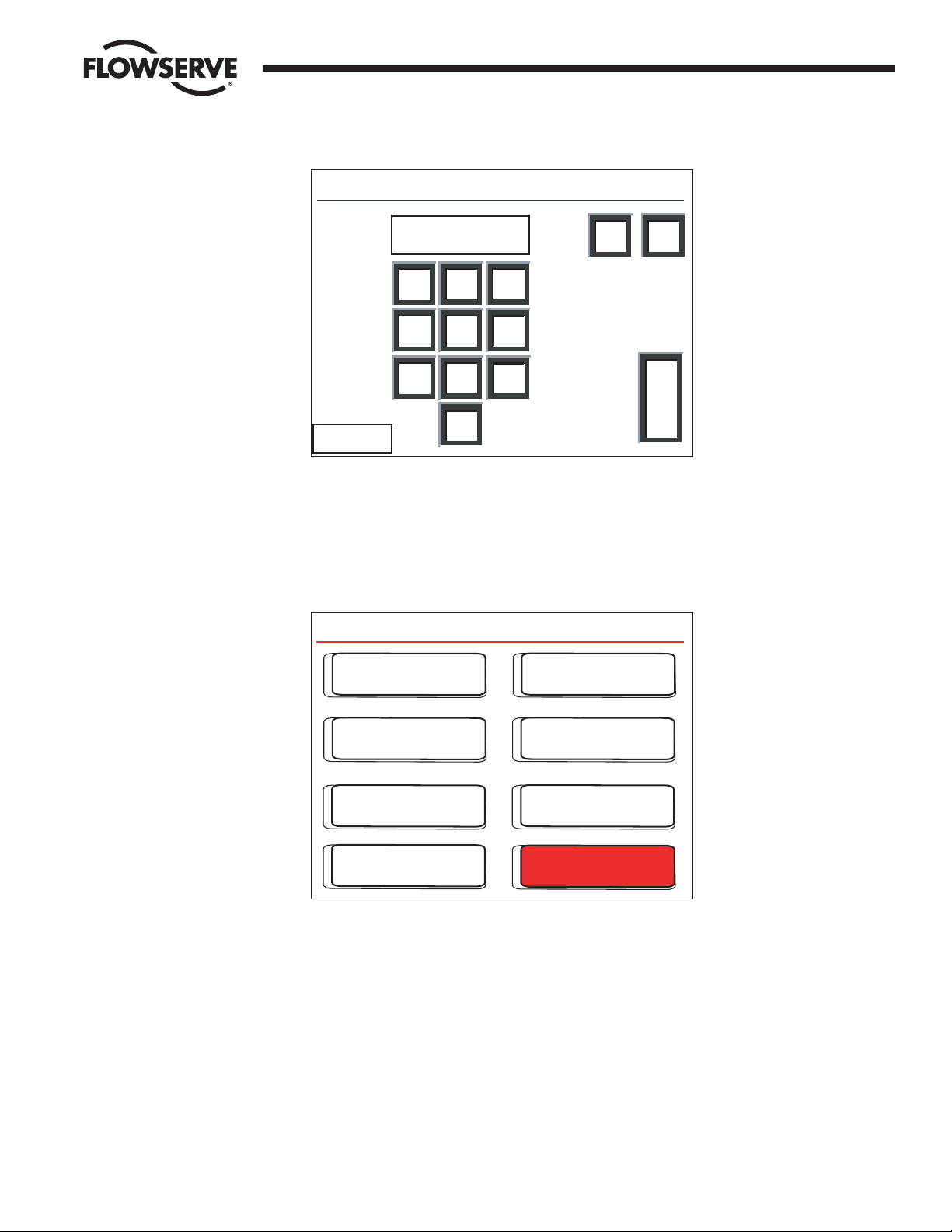
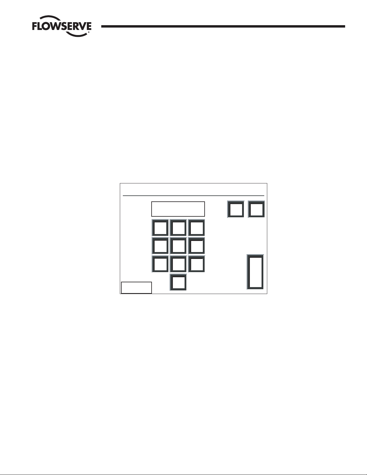
Figure 1-2: The Login screen
Note: Each user level must be a unique password.
Passwords can be four digit numbers. The correct password for View, Control, or Configure will take the
user to the Main Menu (Figure 1-4).
If “Help” is pressed on the password screen, the user is given the opportunity to reset all passwords to
the defaults (Figure 1-3). Please contact Limitorque to obtain the reset password.
Passwords are easily configured via the Change Passwords screen (Figure 9-4).
7
89
6
5
4
1
2
3
0
DEL
CLR
E
N
T
Cancel
Help
Login: Please Enter Your Password
****
Limitorque
ACTIVEPress Anywhere to Begin
Page 7
FCD LMAIM5001-00 DDC-100 Master Station II Installation and Operation Manual 7
Flow Control Division
Limitorque Actuation Systems
Figure 1-3: The Login Help screen
Note: The keys are outlined in red on this screen.
1.4 Main Menu
Figure 1-4: The Main Menu screen
From here, the user is restricted by his role. Each button represents a separate logical region of the
Master Station:
Configure: configure the Master Station and the Network.
Network Status: view the Network from a high level to detect communication errors.
Hot Standby: change over of CPU and configure CPU startup status.
View MOV Status: view the detailed status of each MOV.
Logger: activate logging, either for the network or for data analysis. This data will stream out of the
printer port.
Control MOV: control a MOV’s position.
Emergency Shut Down: initiate or clear an emergency shutdown of the network.
Main Menu ACTIVE
Emergency
Shut Down
Control MOV
Exit
Logger
Configure
Hot Standby
View MOV Status
Network Status
7
89
6
5
4
1
2
3
0
DEL
CLR
E
N
T
<< Back
Login Help: Enter the Reset Password
****
Page 8

8 DDC-100 Master Station II Installation and Operation Manual FCD LMAIM5001-00
Flow Control Division
Limitorque Actuation Systems
This page is intentionally blank.
Page 9

FCD LMAIM5001-00 DDC-100 Master Station II Installation and Operation Manual 9
Flow Control Division
Limitorque Actuation Systems
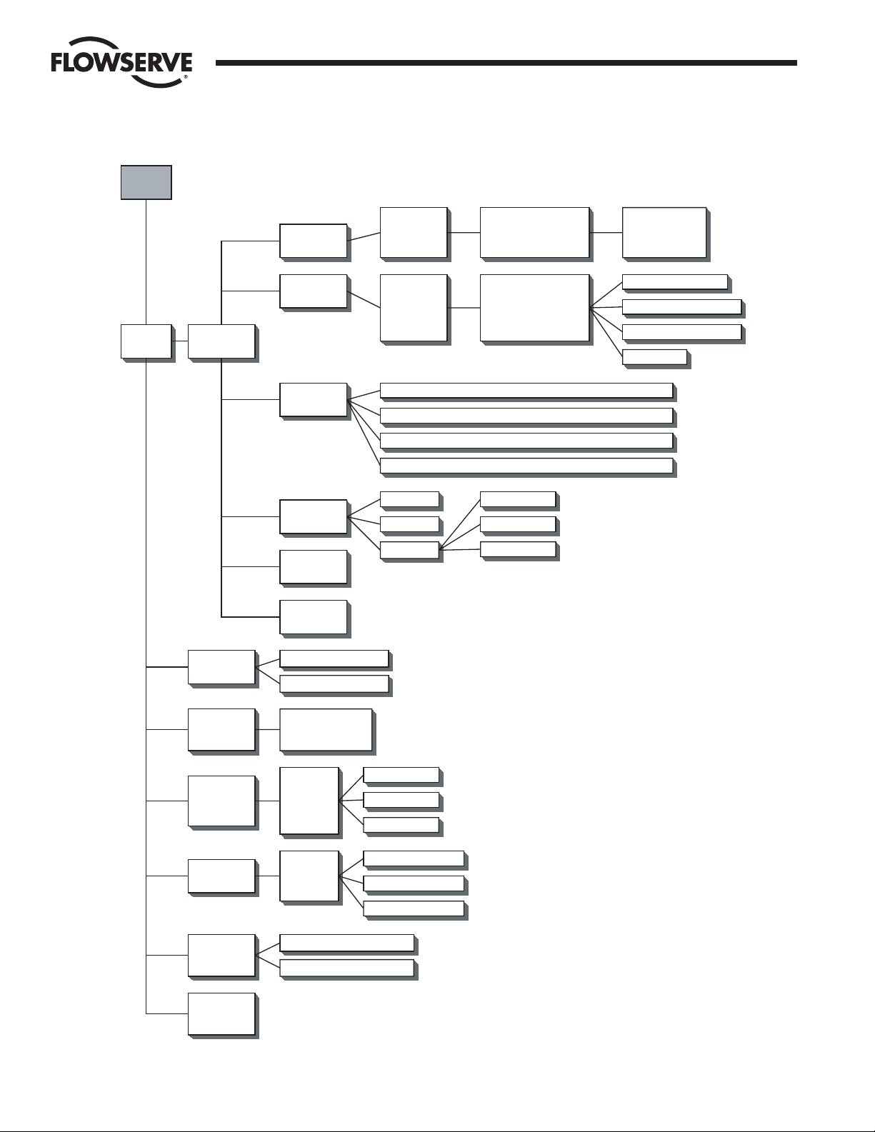
2 Master Station II Screen Flowchart
Figure 2-1 (on the following page) is a flowchart of the Master Station II screens.
Page 10
10 DDC-100 Master Station II Installation and Operation Manual FCD LMAIM5001-00
Flow Control Division
Limitorque Actuation Systems
Figure 2-1: Screen flowchart
Intro
Screen
Main
Menu
Configure
MOV
Network
DCS Port
Ethernet
Port
General
Settings
Change Tags
Save to
Flash
Baud Rate
Retries
Poll Mode
Baud Rate
Stop Bits
Parity
Electrical
IP Address - Octet 1 - Octet 2 - Octet 3 - Octet 4
Mask - Octet 1 - Octet 2 - Octet 3 - Octet 4
Gateway - Octet 1 - Octet 2 - Octet 3 - Octet 4
Standby IP Address - Octet 1 - Octet 2 - Octet 3 - Octet 4
Clock
Version
Password
Timeout
Prop Delay
RTS On Delay
DCS Port Address
RTS On Delay
RTS Off Delay
HMI Control
View
Supervisor
Administrator
Active MOVs 1250
Modbus FC 03 - View
Modbus FC 05/15 - View
Modbus FC 06/16 - View
HMI Control
Hot Standby
Network
Status
View MOV
Status
Control MOV
Emergency
Shutdown
Exit
Change Status
Hot Backup Startup
Communication
Status
MOVs 1-250
Position
MOV Stats
Address 1250
Control
MOVs
1-250
Start Network ESD
Terminate Network ESD
Faults
Alarms
Open/Stop/Close
0-100% Open
Aux Contacts
Page 11

FCD LMAIM5001-00 DDC-100 Master Station II Installation and Operation Manual 11
Flow Control Division
Limitorque Actuation Systems
3 Quick Startup
3.1 Single Master Station Quick Setup Instructions
1. Connect power, earth ground, and network cables per Flowserve recommendations.
2. Turn power on to the Master Station.
3. Wait for the Master Station display to illuminate and the “Press Anywhere To Begin” message.
4. Press the screen and enter the configuration password when prompted. Select Enter.
5. Next select “Configure” then “MOV network”. Select the network baud rate, Time-out, retries, adjust
the Propagation delay and RTS ON delay if required. Next activate the appropriate number of
networked MOVs by making the lamp beside the address green.
6. Select the Back button until the Configuration screen is displayed.
7. From the Configure screen, select “DCS Port.” Select the desired baud rate, stop bits, parity and
electrical standard. Select Next and configure the Master Station DCS port address, adjust the RTS
ON Delay and RTS OFF Delay if required. Select Next for the “Configure DCS Data Table screen”.
8. Configure the data tables for the Master Station.
9. To create the Holding register data table (40000 register block for MOV status) for the Master
Station, select Modbus Fc 03. Select the MOV registers to be available for the DCS by pressing the
toggle switch to illuminate the “green light” on the switch. View the selections and save the changes
and return to the “Configure DCS Data Table” screen.
10. To create the Coils data table (0000 register block for forcing and reading coils) for the Master
Station, select Modbus Fc 05/15. Select the MOV Coils to be available for the DCS by pressing the
toggle switch to illuminate the “green light” on the switch. Save the changes and return to the
“Configure DCS Data Table” screen. Note this feature also creates the Modbus Fc 01 (Read Coils)
data table.
11. To create the Holding register data table (45000 register block for writing holding registers) for the
Master Station, select Modbus Fc 06/16. Select the number of write registers for the MOVs to be
available for the DCS by pressing the toggle switch to illuminate the “green light” on the switch. View
the selections and save the changes and return to the “Configure DCS Data Table screen.”
12. Select Back until reaching the “Configure” screen. Select Back and when prompted to Save,
Select Yes.
13. This will permit a rapid configuration of the Master Station. Further adjustments may be made by
following the procedures outlined in the Master Station Manual.
3.2 Hot Standby Master Station Quick Setup Instructions
Connect power, earth ground, and network cables per Flowserve recommendations.
3.2.1 Configure the Left CPU
1. Turn on power to the left processor of the Master Station. DO NOT apply power to the right half of
the Master Station.
2. Wait for the Master Station display to illuminate and the “Press Anywhere To Continue” message.
3. Press the screen and enter the configuration password when prompted. Select Enter.
Page 12

12 DDC-100 Master Station II Installation and Operation Manual FCD LMAIM5001-00
Flow Control Division
Limitorque Actuation Systems
4. From the Main Menu select Configure.
5. Select Ethernet Port.
6. Complete the setup of the IP address, mask, gateway, and standby address. Select Back from the
Configure window. You will be prompted to Save. Select NO. The Blue window will disappear. Select
Back and return to the Main Menu.
Left unit (default configuration):
IP address: 192.168.0.100
Mask: 255.255.255.0
Gateway: 192.168.0.1
Hot Stby IP: 192.168.0.101
7. From the Main Menu select Hot Standby.
8. Set the Hot Backup Startup as Hot. Select Back.
9. You will be prompted to save the configuration. Select Yes.
10. When the save process is complete turn off the left unit.
3.2.2 Configure the Right CPU
1. Turn on power to the right processor of the Master Station. DO NOT apply power to the left half of
the Master Station.
2. Wait for the Master Station display to illuminate and the “Press Anywhere To Continue” message.
3. Press the screen and enter the configuration password when prompted. Select Enter.
4. From the Main Menu select Configure.
5. Select Ethernet Port.
6. Complete the setup of the IP address, mask, gateway, and standby address. Select Back from the
Configure window. You will be prompted to Save. Select NO. The Blue window will disappear. Select
Back and return to the Main Menu.
Note: The IP address is the standby address of the left processor AND the standby address is the
IP address of the left processor.
Right unit (default configuration):
IP address: 192.168.0.101
Mask: 255.255.255.0
Gateway: 192.168.0.1
Hot Stby IP: 192.168.0.100
7. From the Main Menu select Hot Standby.
8. Set the Hot Backup Startup as Standby. Select Back.
9. You will be prompted to save the configuration. Select Yes.
10. When the save process is complete turn off the right unit.
3.2.3 Configure the Master Station for network control
1. Apply power to the left and right CPUs. Wait for the Master Station display to illuminate and the
“Press Anywhere To Continue” message to appear. One Master Station will display “Active” the other
will display “Standby”.
Left Right
IP IP
Standby Standby
Page 13

FCD LMAIM5001-00 DDC-100 Master Station II Installation and Operation Manual 13
Flow Control Division
Limitorque Actuation Systems
2. Press the screen of the ACTIVE Master Station and enter the configure password when prompted.
Select Enter.
3. From the Main Menu, select Configure
4. Next select Configure the MOV network. Select the network baud rate, Time-out, retries, adjust the
Propagation delay and RTS ON delay if required. Next activate the number of networked MOVs by
making the button beside the address green.
5. Select the Back button until the Configuration screen is displayed.
6. Configure the data tables for the Master Station.
a. To create the Holding register data table (40000 register block for MOV status) for the Master
Station, select Modbus Fc 03. Select the MOV registers to be available for the DCS by pressing
the toggle switch to illuminate the “green light” on the switch. Save the changes and return to
the “Configure DCS Data Table screen.”
b. To create the Coils data table (0000 register block for forcing and reading coils) for the Master
Station, select Modbus Fc 05/15. Select the MOV Coils to be available for the DCS by pressing
the toggle switch to illuminate the “green light” on the switch. Save the changes and return to
the “Configure DCS Data Table” screen. Note this feature also creates the Modbus Fc 01 (Read
Coils) data table.
c. To create the Holding register data table (45000 register block for writing holding registers) for
the Master Station, select Modbus Fc 06/16. Select the number of write registers for the MOVs
to be available for the DCS by pressing the toggle switch to illuminate the “green light” on the
switch. Save the changes and return to the “Configure DCS Data Table screen.”
7. Select Back until reaching the “Configure” screen. Select Back and when prompted to Save,
select Yes.
Note: All network configuration data, MOV data, and Master Station Data table configuration
parameters will be automatically saved to the standby Master Station.
DCS Port configuration data will not be saved as these ports are independently configured.
Items NOT saved to the Standby Master Station:
DCS Address
DCS Baud Rate
DCS Electrical Standard
DCS Stop bits
DCS Parity
DCS RTS On Delay
DCS RTS Off Delay
DCS Startup (Hot or Standby)
IP Address
IP Mask
Gateway
Standby IP Address
8. This will permit a rapid configuration of the Master Station. Further adjustments may be made by
following the procedures outlined in the Master Station Manual.
Page 14

14 DDC-100 Master Station II Installation and Operation Manual FCD LMAIM5001-00
Flow Control Division
Limitorque Actuation Systems
This page is intentionally blank.
Page 15
FCD LMAIM5001-00 DDC-100 Master Station II Installation and Operation Manual 15
Flow Control Division
Limitorque Actuation Systems
4 Connections
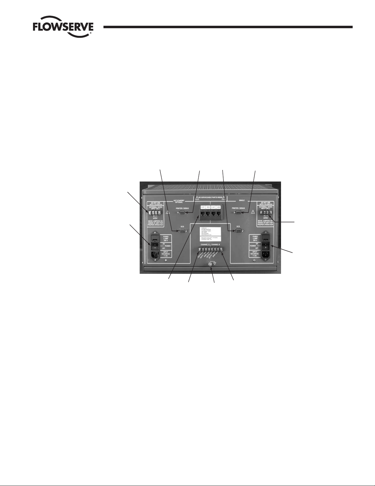
4.1 Master Station Rear Panel Connections
Figure 4-1: Master Station connections
1. Ethernet Ports, RJ-45 connectors. One port is designated for MNET (Modbus Ethernet TCP/IP). The
other port is for the webserver. Either port may be used for either function as they are connected to
the same CPU.
2. Printer / Debug Port. DB-9 Female connector. RS-232 port. Used for Master Station diagnostics.
11
10
9
1
12
8
3
7
6
2
4
5
Page 16
16 DDC-100 Master Station II Installation and Operation Manual FCD LMAIM5001-00
Flow Control Division
Limitorque Actuation Systems
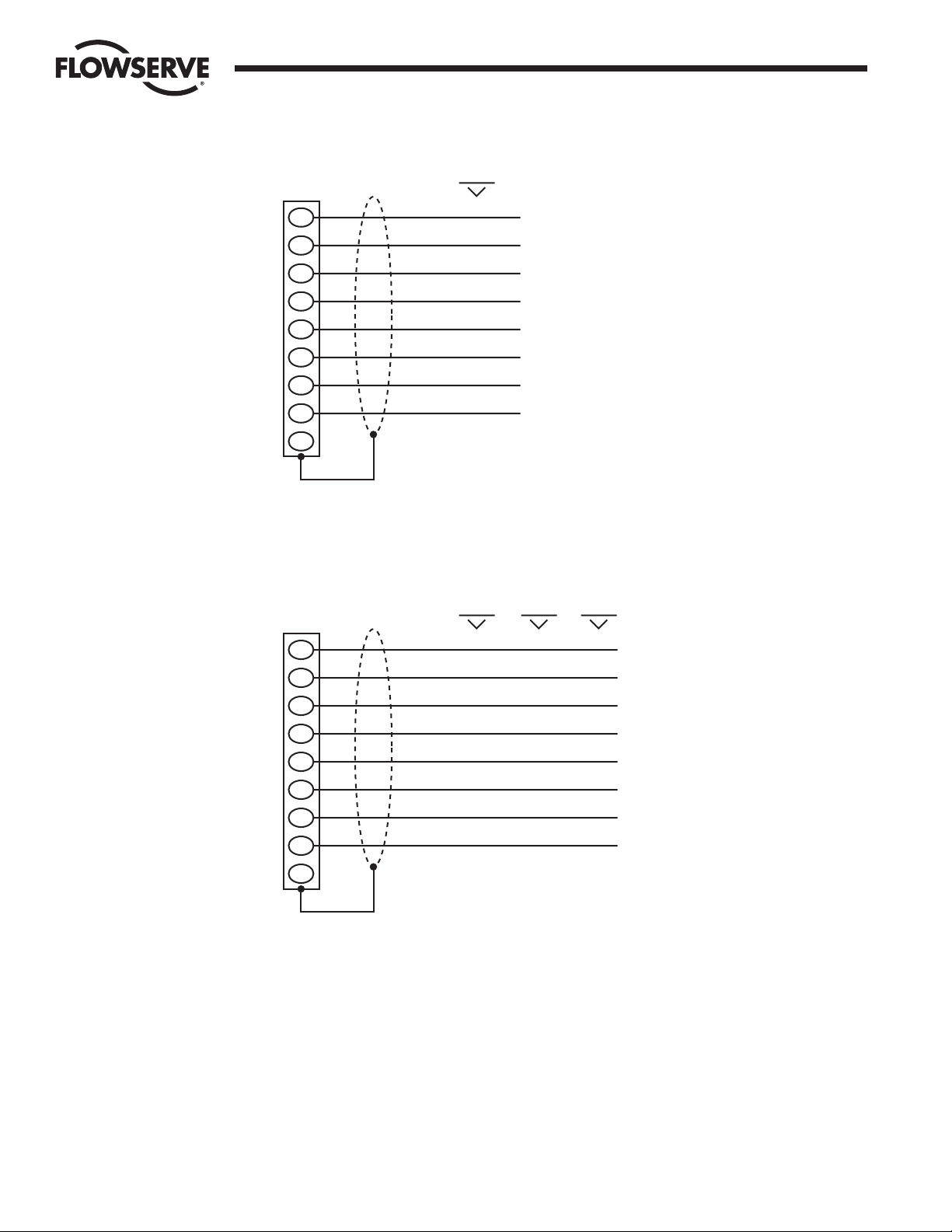
Figure 4-2: Debug Port Connection
3. DCS Port. DB-9 Female connector. Port may be RS-232 or RS-422 or RS-485. Each electrical standard
uses a different wiring convention.
Figure 4-3: DCS Port Connection
4. Auxiliary 24 VDC power connection. Master Station may be configured for 24 VDC power. This will require
the jumpers inside the Master Station to be configured for 24 VDC. DO NOT use 120 VAC when using
24 VDC power.
5. Main power switch and connector for 120 – 240 VAC. DO NOT use when 24 VDC power is applied.
RS 232
DB-9
6
4
7
2
1
8
3
5
9
N/C
DSR
DTR
RTS
RXD
DCD
CTS
TXD
GND
DB-9
6
4
7
2
1
8
3
5
9
RS 232
DSR
DTR
RTS
RXD
DCD
CTS
TXD
GND
N/C
RS 485
TXRXD+
TXRXD-
GND
RS 422
RXD-
RXD+
TXD+
TXD-
GND
Page 17

FCD LMAIM5001-00 DDC-100 Master Station II Installation and Operation Manual 17
Flow Control Division
Limitorque Actuation Systems
Table 4-1: Network Channel B Connection
Connector MX-DDC UEC-3-DDC
Data 41 TB4 D-S
Data * 29 TB4 D-S*
Shield
6. Electrostatic Ground. A good quality earth ground MUST be attached to the Master Station. An
effective local, low-impedance earth ground (less than 5 ohms) is required.
Table 4-2: Network Channel A Connection
Connector MX-DDC UEC-3-DDC
Data 16 TB3 D-M
Data * 15 TB3 D-M*
Shield
7. Hot Standby unit main power switch and connector for 120 – 240 VAC. DO NOT use when 24 VDC
power is applied.
8. Hot Standby auxiliary 24 VDC power connection. Master Station may be configured for 24 VDC
power. This will require the jumpers inside the Master Station to be configured for 24 VDC. DO NOT
use 120 VAC when using 24 VDC power.
9. Hot Standby DCS Port. DB-9 Female connector. Port may be RS-232 or RS-422 or RS-485. Each
electrical standard uses a different wiring convention.
10. Hot Standby Printer / Debug Port. DB-9 Female connector. RS-232 port. Used for Master Station
diagnostics.
4.2 Master Station Wiring Requirements
The network cable connects the field units to the host controller or Master Station. Belden 3074F, 3105A,
or 9841 shielded, twisted-pair cable should be used. The use of other cables may result in a reduction of
internodal distances or increased error rate, and is the user’s responsibility.
Belden 3074F Specifications
• Total cable length between repeaters or nodes with repeaters: up to 19.2 kbps: 5000' (1.52 km)
For loop mode, this is the total length between operating field units. If a field unit loses power, the relays
internal to the field unit connect the A1 Channel to the A2 Channel, which effectively doubles the length of
the cable (assuming a single field unit fails). To ensure operation within specifications in the event of
power failure to field units, this consideration must be added. Example: To ensure operation within
specification when any two consecutive field units lose power, the maximum length of cable up to 19.2
bkps should not exceed 5000' (1.52 km) per every four field units. See Section 3.1.2.3, Network Cable
Connection to Host Controller or Master Station.
Key Specifications
• Resistance/1000 ft = 18 AWG (7 x 26) 6.92 ohms each conductor (13.84 ohms for the pair)
• Capacitance/ft = 14 pF (conductor-to-conductor)
• Capacitance/ft = 14 pF (conductor-to-shield)
Page 18

18 DDC-100 Master Station II Installation and Operation Manual FCD LMAIM5001-00
Flow Control Division
Limitorque Actuation Systems
Belden 3105A Specifications
• Total cable length between repeaters or nodes with repeaters: up to 19.2 kbps: 4500' (1.37 km)
For loop mode, this is the total length between operating field units. If a field unit loses power, the relays
internal to the field unit connect the A1 Channel to the A2 Channel, which effectively doubles the length of
the cable (assuming a single field unit fails). To ensure operation within specifications in the event of
power failure to field units, this consideration must be added. Example: To ensure operation within
specification when any two consecutive field units lose power, the maximum length of cable up to 19.2
bkps should not exceed 4500' (1.37 km) per every four field units. See Section 3.1.2.3, Network Cable
Connection to Host Controller or Master Station.
Key Specifications
• Resistance/1000 ft = 22 AWG (7 x 30) 14.7 ohms each conductor (29.4 ohms for the pair)
• Capacitance/ft = 11.0 pF (conductor-to-conductor)
• Capacitance/ft = 20.0 pF (conductor-to-shield)
Belden 9841 Specifications
• Total cable length between repeaters or nodes with repeaters: up to 19.2 kbps: 3500' (1 km)
For loop mode, this is the total length between operating field units. If a field unit loses power, the relays
internal to the field unit connect the A1 Channel to the A2 Channel, which effectively doubles the length of
the cable (assuming a single field unit fails). To ensure operation within specifications in the event of
power failure to field units, this consideration must be added. Example: To ensure operation within
specification when any two consecutive field units lose power, the maximum length of cable up to 19.2
bkps should not exceed 3500' (1 km) per every four field units. See Section 3.1.2.3, Network Cable
Connection to Host Controller or Master Station.
Key Specifications
• Resistance/1000 ft = 24 AWG (7 x 32) 24 ohms each conductor (48 ohms for the pair)
• Capacitance/ft = 12.8 pF (conductor-to-conductor)
• Capacitance/ft = 23 pF (conductor-to-shield)
Page 19
FCD LMAIM5001-00 DDC-100 Master Station II Installation and Operation Manual 19
Flow Control Division
Limitorque Actuation Systems
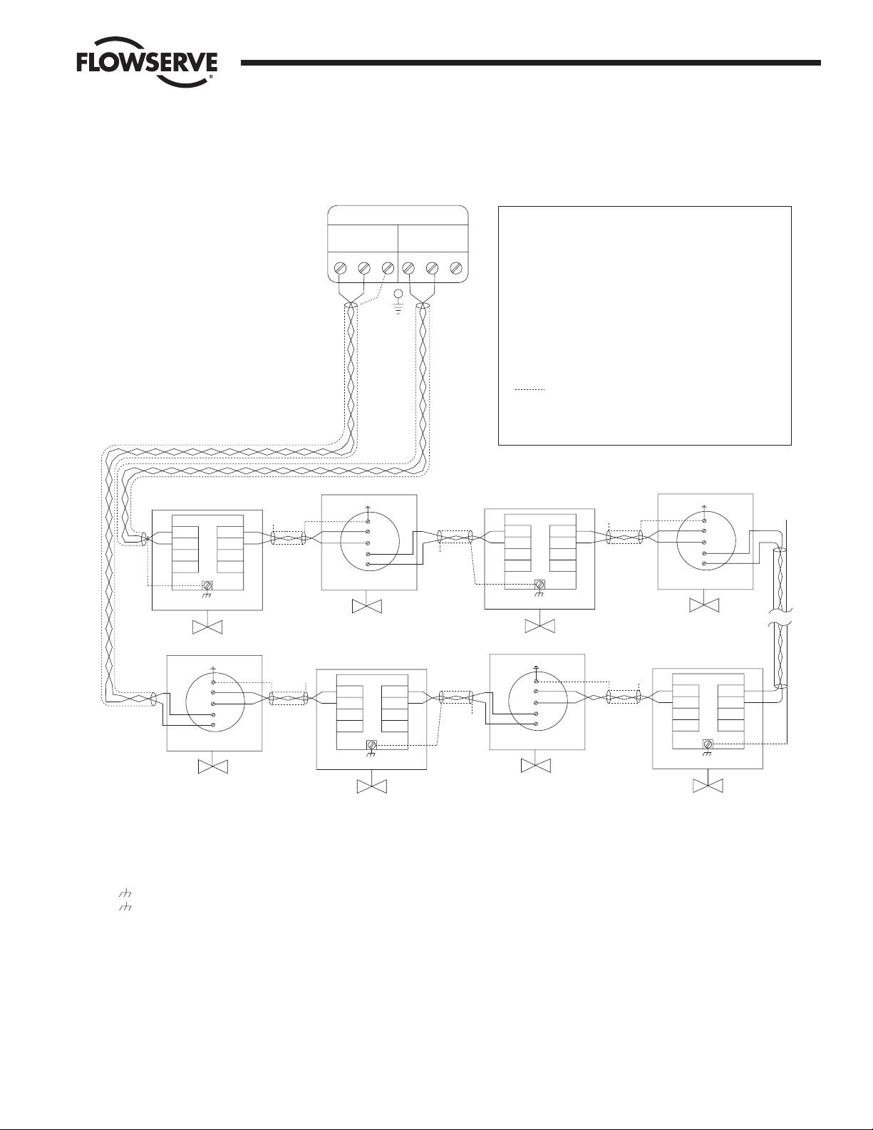
4.3 Master Station Network Schematic
Figure 4-4: DDC-100 Redundant Loop Network
Diagnostic Note:
Earth Ground Note:
MOV-3
A2
A2*
A1
A1*
TB5
MOV-247
A1
A1*
A2
A2*
TB5
N/ C
MOV-249
D-M
D-M*
D-S
D-S*
A1
A1*
A2
A2*
TB4
TB3
TB5
Notes:
Legend
MOV
D-M
D-M*
D-S
D-S*
N/C
Data terminal is positive with respect to data* terminal
See Note 5
See Note 5
See Note 5
1) Belden 3074F, 3105A, or 9841 shielded cable is recommended.
2) Correct polarity for field unit and network controller
connection is necessary for proper operation.
3) Connections shown are typical. The number of
MOVs shown may not indicate true system size.
4) Earth ground: ground rod
5) Earth gro
und: ground rod or lug in
actuator if actuator is grounded.
Polarity and level of the network’s data connection can
be checked by measuring voltage between data and
data* terminals. This voltage should be greater than
+200mVDC with network controlle
r network ports
disconnected.
If low impedance earth ground is not available at
each actuator, contact engineering for alternative
earth ground surge protection strategies.
A1*
MOV-2
See Note 5
N/C
A2*
N/C
MOV-248
See Note 5
N/C
MOV-4
See Note 5
N/C
16
15
41
29
29
41
D-S
D-S*
D-M
D-M*
TB3
TB4
MOV-1
A2
A2*
A1
A1*
TB5
See Note 5
D-S
D-S*
D-M
D-M*
TB3
TB4
D-M
D-M*
D-S
D-S*
TB4
TB3
15
16A2A1
A1*
A2*
29
41
15
16A2A1
A1*
A2*
29
41
15
16A2A1
Motor-Operated Valve
Data A1
Data A1*
Data A2
Data A2*
Data A1 (UEC-3-DDC)
Data A1*(UEC-3-DDC)
Data A2* (UEC-3-DDC)
Shield
No Connection
Data A2 (UEC-3-DDC)
N/C
MOV-250
See Note 5
A1*
A2*
29
41
15
16A2A1
N/C
Channel A Channel B
MASTER STATION II
Page 20

20 DDC-100 Master Station II Installation and Operation Manual FCD LMAIM5001-00
Flow Control Division
Limitorque Actuation Systems
This page is intentionally blank.
Page 21
FCD LMAIM5001-00 DDC-100 Master Station II Installation and Operation Manual 21
Flow Control Division
Limitorque Actuation Systems
5 Configuration
5.1 Login
From the Main Menu, touching the Configure button will prompt for the Configure password if the user is
not already logged in as the Configure user (Figure 5-1). This screen will not be displayed if the initial
password entered is the configure password.
Figure 5-1: The Configure Password screen
5.2 Configure Main Screen
After successfully logging in as the Configure user, the Configure main screen will be presented
(Figure 5-2).
7
89
6
5
4
1
2
3
0
DEL
CLR
E
N
T
<< Back
Login: Enter Configuration Password
****
Page 22

22 DDC-100 Master Station II Installation and Operation Manual FCD LMAIM5001-00
Flow Control Division
Limitorque Actuation Systems
Figure 5-2: The Configure main screen
The Configure main screen allows the user to configure five areas of the Master Station:
MOV Network: includes baud rate for network, retries, poll mode, timeout, propagation delay, RTS ON
delay, and screens to allow the user to graphically select the active MOVs.
DCS Port: includes baud rate for DCS communication, stop bits, parity, electrical standard, DCS address,
RTS ON delay, RTS OFF delay, HMI state during DCS communication traffic, and selectable register
maps for Modbus function code 3, Modbus function code 5/15, and Modbus function code 6/16.
Ethernet Port: includes IP Address, Mask, Gateway, and Hot Standby IP Address.
General Settings: includes Clock, Passwords, and Version information.
Hot Standby: includes buttons for forcing a state switch from Hot to Standby or Standby to Hot, indicates
the current state, and the Hot Backup Startup state.
Note: CONFIGURATION CHANGES WILL BE LOST UNLESS SAVED TO FLASH. It is important that desired
configuration changes are saved to flash by pushing the green “Save Config to Flash” button before
exiting. Attempting to exit without saving will cause a prompt to save changes.
Figure 5-3: Confirmation to Change configuration screen
Yes
No
Do you wish to save changes
made to this configuration?
Configuration Changed
MOV
Network
DCS Port
Ethernet
Port
General
Settings
Change Tags
Save Config
to Flash
Configure ACTIVE
<< Back
Page 23

FCD LMAIM5001-00 DDC-100 Master Station II Installation and Operation Manual 23
Flow Control Division
Limitorque Actuation Systems
Figure 5-4: Saving Changes to Flash screen
Figure 5-5: Configuration Not Changed screen
OK
There have been no changes
made to the configuration.
Configuration Not Changed
Please wait while the
configuration is saved to
flash.
This operation requires
approximately 20 seconds.
Please Wait
Page 24
24 DDC-100 Master Station II Installation and Operation Manual FCD LMAIM5001-00
Flow Control Division
Limitorque Actuation Systems
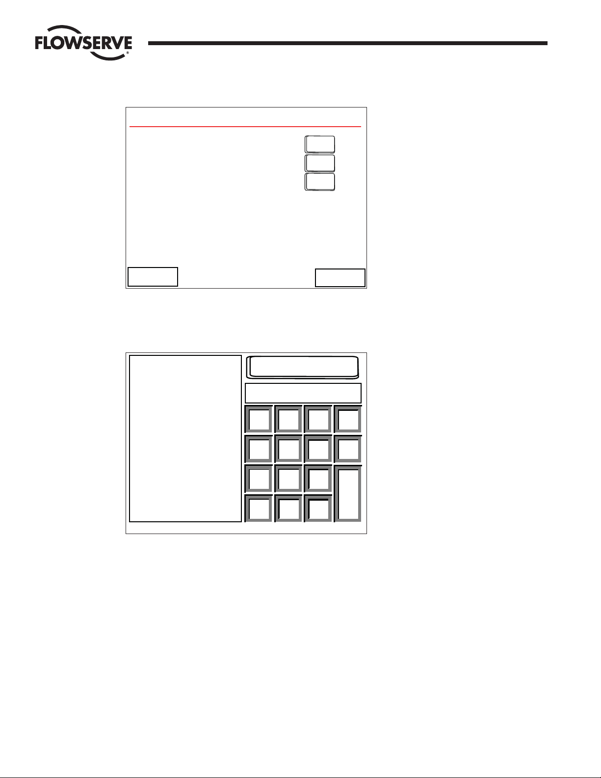
5.3 Change Tags
Each MOV has a Tag name associated with it to provide a user-friendly identification. These tags can be
edited by the user via the Change Tags screen (Figure 5-6).
Figure 5-6: Change Tag Name screen
The MOV Address indicates the MOV currently being edited. The arrows to the left and right of the MOV
Address allow the user to navigate between MOVs. The +10 and -10 buttons allow the user to rapidly skip
between MOVs.
In the center of the screen the MOV tag name is displayed. The Pos and Pos arrows allow the user to edit
different characters in the tag name. The Character + and Character - arrows allow the user to increase a
character, for example A to B to C or to decrease a character, C to B to A. In this manner, the user may
rapidly create custom tags for each MOV.
It is important to touch the “Save Tag” button before the user edits a different MOV or exits the screen.
“Save Tag” must be touched for each tag changed. Failing to touch “Save Tag” will result in loss of data.
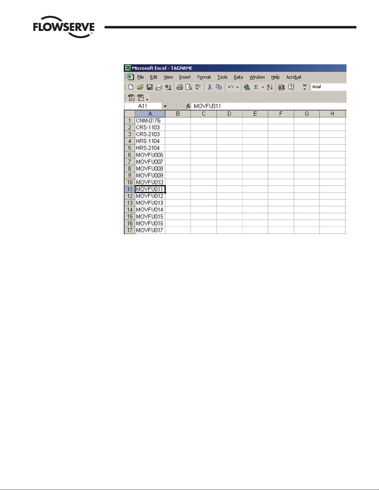
5.3.1 Altering Tag Names with Microsoft Excel
1. Attach a PC to the Master Station Ethernet port. Configure the PC Ethernet port to communicate with
the Master Station.
Example:
Master Station PC
IP 192.168.0.100 192.168.0.101
Mask 255.255.255.0 255.255.255.0
Gateway 192.168.0.1 192.168.0.1
Standby IP 0.0.0.0 0.0.0.0
2. Copy the TAGNAME file to a PC using a FTP (File Transfer Protocol).
3. Open the TAGNAME file with Excel.
4. Column A will contain 250 rows corresponding to the 250 allowable addresses for the Master Station.
5. Example Row 1 is MOV Address 1, Row 2 is MOV Address 2, etc.
6. Edit the tag name for each address.
7. The Master Station supports the ASCII character set.
Change Tag Name
MOV Address
Character -
Tag Value
MOVFU001
Character +
Pos -
Pos +
<< Back
Save Tag
1
-10
+10
Page 25
FCD LMAIM5001-00 DDC-100 Master Station II Installation and Operation Manual 25
Flow Control Division
Limitorque Actuation Systems
8. Tag names are limited to 8 characters. Spaces and other symbols are considered a character.
9. Save the file in .CSV (comma separated value) format.
10. Using FTP, copy the TAGNAME file to the Active Master Station.
11. Power cycle the Master Station to load the new TAGNAME file. On power-up the new tag names will
appear on the ACTIVE Master Station.
12. For a Hot Standby Master Station, after the Active unit has been power cycled, enter the
configuration screens and save the current configuration. This will transfer the new TAGNAME file to
the Standby Master Station.
Page 26

26 DDC-100 Master Station II Installation and Operation Manual FCD LMAIM5001-00
Flow Control Division
Limitorque Actuation Systems
This page is intentionally blank.
Page 27

FCD LMAIM5001-00 DDC-100 Master Station II Installation and Operation Manual 27
Flow Control Division
Limitorque Actuation Systems
6 MOV Network Configuration
These screens allow the user to configure the MOV network for operation. The first screen presented allows the user to
configure Baud Rate, Retries, and Poll Mode (Figure 6-1).
Figure 6-1: The Configure MOV Network screen
Once these parameters are configured, the “Auto Search” button can be pressed. This will cause the Master Station to
poll the network, searching for active MOVs. All inactive MOVs will be disabled in its configuration (Figure 6-2).
Figure 6-2: Auto-configuring Network screen
Touching “Next >>” will take the user to the next configuration screen on which the Timeout, First Active MOV, Last
Active MOV, Total MOVs, Propagation Delay, and RTS ON Delay can be configured (Figure 6-3).
Auto-Configuring Network
The Network is being auto-configured.
This process can take several minutes.
Please wait.
Estimated Time Remaining: # minutes
Baud Rate
4800
9600
19200
Retries
1
2
Redund. Loop
A Port Only
B Port Only
Configure MOV Network
Poll Mode
<< Back
Next >>
Auto Search
Page 28
28 DDC-100 Master Station II Installation and Operation Manual FCD LMAIM5001-00
Flow Control Division
Limitorque Actuation Systems
Figure 6-3: The second Configure MOV Network screen
Touching an “Edit” button will take the user to a screen similar to Figure 6-4. Each screen provides information about the
parameter being configured, the current value, and the valid values or range.
Figure 6-4: The Timeout Edit screen
The remaining eight screens under the Configure MOV Network section allow the user to select, graphically, which MOVs
are active (Figure 6-5).
Timeout
Current Value:
350
200-5000 (ms)
Valid Range:
MOV response
time-out period.
1 ms increments
(Min. 200 msec.)
350
<< Back
7
89
6
5
4
1
2
3
0.
CLR
DEL
-
E
N
T
EDIT
EDIT
EDIT
EDIT
EDIT
EDIT
Timeout (ms): 350
Prop. Delay (ms): 10
RTS ON Delay (ms): 10
Total Active MOVs: 32
First Conf. MOV: 1
Last Conf. MOV: 32
Configure MOV Network
<< Back
Next >>
Page 29

FCD LMAIM5001-00 DDC-100 Master Station II Installation and Operation Manual 29
Flow Control Division
Limitorque Actuation Systems
Figure 6-5: The Active MOVs screen
MOVs are represented by green/red lamps. Active MOVs are green, while inactive MOVs are red. Touching the number of
an MOV will toggle its state from Active to Inactive or Inactive to Active.
By selecting the Next button, the Master Station screen will advance to the next screen to enable/disable additional
MOVs. There are eight screens for activating all 250 MOVs.
Table 6-1: MOV activation pages
Page MOVs
1 of 8 1-32
2 of 8 33-64
3 of 8 65-96
4 of 8 97-128
5 of 8 129-160
6 of 8 161-192
7 of 8 193-224
8 of 8 225-250
Next >>
<< Back
001 002 003 004 005 006 007
008 009 010 011 012 013 014
015 016 017 018 019 020 021
022 023 024 025 026 027 028
029 030 031 032
Press on a MOV to toggle activation
MOV Not Active
MOV Active
LEGEND
Active MOVs MOVs 1-32 Page 1 of 8
Page 30

30 DDC-100 Master Station II Installation and Operation Manual FCD LMAIM5001-00
Flow Control Division
Limitorque Actuation Systems
This page is intentionally blank.
Page 31

FCD LMAIM5001-00 DDC-100 Master Station II Installation and Operation Manual 31
Flow Control Division
Limitorque Actuation Systems
7 DCS Port Configuration
7.1 Introduction
DCS Port: includes baud rate for DCS communication, stop bits, parity, electrical standard, DCS address,
RTS ON delay, RTS OFF delay, HMI state during DCS communication traffic, and selectable register maps
for Modbus function code 3, Modbus function code 5/15, and Modbus function code 6/16.
These screens allow the user to configure the DCS port for operation. The first screen presented allows
the user to configure Baud Rate, Retries, Parity, and Electrical connection (Figure 7-1).
Figure 7-1: The Configure DCS Port screen
Touching “Next >>” will take the user to the next DCS Port configuration screen on which the DCS Port
Address, RTS ON Delay, RTS OFF Delay, and HMI control may be disabled when DCS communication
traffic is active (Figure 7-2).
Configure DCS Port
Baud Rate
Stop Bits
Electrical
1
2
RS-232
RS-422
RS-485
None
Even
Odd
Parity
4800
9600
19200
38400
57600
115200
<< Back
Next >>
Page 32

32 DDC-100 Master Station II Installation and Operation Manual FCD LMAIM5001-00
Flow Control Division
Limitorque Actuation Systems
Figure 7-2: The DCS Port Configuration screen
Touching “EDIT” next to “DCS Address,” “RTS ON Delay (ms)” or “RTS OFF Delay (ms)” will allow the
user to enter new values.
Figure 7-3: DCS Port Address screen
DCS Port Address
Current Value:
1
1-247
Valid Range:
Modbus node
address for this
Master Station
for communication
to DCS or PLC.
1
<< Back
7
89
6
5
4
1
2
3
0.
CLR
DEL
-
E
N
T
DCS Port
DCS Address:
RTS ON Delay (ms):
RTS OFF Delay (ms):
HMI State during DCS Comm Traffic
HMI Control On
<< Back
1
0
0
EDIT
EDIT
EDIT
EDIT
EDIT
EDIT
Next >>
Page 33

FCD LMAIM5001-00 DDC-100 Master Station II Installation and Operation Manual 33
Flow Control Division
Limitorque Actuation Systems
Figure 7-4: RTS ON Delay screen
Press Back after editing values.
Figure 7-5: RTS OFF Delay screen
Press Back after editing values.
Touching “Next >>” on the DCS Port Configuration screen will take the user to the next DCS Data Table
Configuration screen.
7.2 Data Table Configuration
The Master Station data table is configurable for the Modbus Function codes 01, 05, 03, 05/15, 06/16.
The Modbus function codes 02 and 04 have a fixed data table and do not permit user alteration
(Figure 7-6).
RTS Off Delay
Current Value:
0
1-65535
Valid Range:
Time delay
(1 ms each incr.)
after the last
char. transmit
and before RTS
is dropped.
0
<< Back
7
89
6
5
4
1
2
3
0.
CLR
DEL
-
E
N
T
RTS On Delay
Current Value:
0
1-65535
Valid Range:
Time delay
(1 ms incr.)
between asserting
RTS and the
transmission of
data.
0
<< Back
7
89
6
5
4
1
2
3
0.
CLR
DEL
-
E
N
T
Page 34

34 DDC-100 Master Station II Installation and Operation Manual FCD LMAIM5001-00
Flow Control Division
Limitorque Actuation Systems
Figure 7-6: The Select Data Table screen
Touching the “View/Edit” button for Modbus 03 will take the user to a screen similar to Figure 7-7. This
screen permits the user to select the MOV parameters for holding register status.
<< Back Top Screen
Configure DCS Data Table
View/Edit
View/Edit
View/Edit
View/Edit
View/Edit
View/Edit
Read Only
Read/Write
Modbus Fc 03:
Modbus Fc 05/15:
Modbus Fc 06/16:
MNET Status
Page 35

FCD LMAIM5001-00 DDC-100 Master Station II Installation and Operation Manual 35
Flow Control Division
Limitorque Actuation Systems
03 —Read Holding Registers
Reads the binary contents of holding registers in the field units. The Master Station will allow the user to
select the number of registers to be visible per field unit up to a maximum of 10 (registers 4 – 13). Default
setting will display field unit registers 8 and 9.
Figure 7-7: The Register Selection screen
When the user selects the register(s) to be mapped into the DCS Data table, the toggle switch will display
a green dot. All registers between the first selected toggle switch and the last toggle switch selected will
be displayed. Once the selections have been completed, touching the “View >>” button will display a
sample Data Table for the first 12 registers (Figure 7-8).
Note: Once the selection is made, the “Store” button must be pressed for the configuration to be
stored.
Figure 7-8: The Sample Data Table screen
Touching the “<< Back” button will take the user to the register selection screen where the chosen register
format may be saved or altered to another configuration. (Figure 7-7).
Data Table Modbus Function Code 03
Reg.# MOV# Meaning
40001 1 Pos
40002 1 Status
40003 2 Pos
40004 2 Status
40005 3 Pos
40006 3 Status
40007 4 Pos
40008 4 Status
40009 5 Pos
40010 5 Status
40011 6 Pos
40012 6 Status
Reg.# MOV# Meaning
<< Back
Modbus Holding Registers
Select Desired Registers/MOV
Torque
Volts Analog #1 Analog #2
D. outFaultStatusPosition
DI #1 DI #2
Always
On
Store
View >>
<< Back
Page 36

36 DDC-100 Master Station II Installation and Operation Manual FCD LMAIM5001-00
Flow Control Division
Limitorque Actuation Systems
Selecting a register for a specific field unit follows the convention listed below.
Name MX-DDC UEC-3-DDC
Torque Torque (current) Average Torque (Opt)
Volts Actual Volts Not Used
Analog #1 Analog Input (User) Analog Input (User)
Analog #2 Analog Input (User) Analog Input (User)
Position Valve Position (0 - 100%) Valve Position (0 - 100%)
Status Register
Bit 00 Opened Opened
01 Closed Closed
02 Stopped Stopped
03 Opening Opening
04 Closing Closing
05 Valve Jammed Valve Jammed
06 Local Mode Selected Local Mode Selected
07 Combined Fault * Combined Fault *
08 Thermal Overload Fault Thermal Overload Fault
09 Future Use Fail De-Energize
10 Channel A Fault Channel A Fault
11 Channel B Fault Channel B Fault
12 Open Torque Switch Fault Open Torque Switch Faul
13 Close Torque Switch Fault Close Torque Switch Fault
14 Manual Operation Manual Operation
15 Phase Error Phase Error
Fault Register
Bit 00 Not Used Open Verify Fault
01 Not Used Close Verify Fault
02 Not Used Open De-Energize Fault
03 Not Used Close De-Energize Fault
04 Phases Missing Phases Missing
05 Phase Reversed Phase Reversed
06 Not Used Manual Mid to Open
07 Not Used Manual Open to Mid
08 Not Used Manual Mid to Close
09 Not Used Manual Close to Mid
10 Network ESD is ON ** Network ESD is ON**
11 Local ESD is ON Local ESD is ON
12 Unit Reset since last poll Unit Reset since last poll
13 Local Stop Selected Wrong Rotation
14 Opening in Local Opening in Local
15 Closing in Local Closing in Local
Page 37

FCD LMAIM5001-00 DDC-100 Master Station II Installation and Operation Manual 37
Flow Control Division
Limitorque Actuation Systems
Name MX-DDC UEC-3-DDC
Digital Output
Bit 00 Close Contactor Close Contactor
01 Open Contactor Open Contactor
02 AS-1 User (K3)
03 AS-2 SW-93 LED
04 AS-3 SW-93 LED
05 AS04 User (K6)
06 AR-1, Opt N/A
07 AR-2, Opt N/A
08 AR-3, Opt Bits 08-15
09 Network Relay Field Unit Software
10 - 15 Not Used Version ID
Digital Inputs 1
Bit 00 Remote Mode Selected Remote Mode Selected
01 Thermal Overload Fault Thermal Overload Fault
02 Open Torque Switch Open Torque Switch
03 Open Limit Switch Open Limit Switch
04 Close Torque Switch Close Torque Switch
05 Close Limit Switch Close Limit Switch
06 Not Used Aux. Open Input
07 Not Used Aux. Close Input
08 User 0, Terminal-21 User 0, TB2-1
09 User 1, Terminal-10 User 1, TB2-2
10 User 2, Terminal-9 User 2, TB2-3
11 User 3, Terminal-6 User 3, TB2-4
12 User 4, Terminal-7 User 4, TB2-5
13 User 5, Terminal-5 User 5, TB2-6
14 User 6, Opt, Terminal-23 User 6, I/O Module Only
15 User 7, Opt, Terminal-24 User 7, I/O Module Only
Digital Inputs 2
Bit 00 Not Used Analog in 1 Lost
01 Not Used Analog in 2 Lost
02 Analog in 1 Lost Analog in 3 Lost
03 Analog in 2 Lost Analog in 4 Lost
04 Network A/B Lost Network A/B Lost
05 Not Used Reserved
06 DDC Bd. Present Reserved
07 I/O Opt Board Present Reserved
08 Not Used Reserved
09 Not Used Reserved
10 Not Used Reserved
11 Not Used Reserved
12 Phase Lost Phase Lost
13 Phase Reverse Phase Reverse
14 User 8, Opt, Terminal-25 User 8, I/O Module Only
15 Not Used User 9, I/O Module Only
Page 38

38 DDC-100 Master Station II Installation and Operation Manual FCD LMAIM5001-00
Flow Control Division
Limitorque Actuation Systems
DCS Requested Register = [(field unit address –1) * number of registers per unit] + desired register
Touching the “View/Edit” button for Modbus 05/15 will take the user to a screen similar to Figure 7-9.
This screen permits the user to select desired coils/MOV.
01 —Read Coil Status
Reads the ON/OFF status of discrete outputs (coils) in the field units. This data table is configured with the
Modbus Function code 05/15 parameters.
05 —Force Single Coil / 15 —Force Multiple Coil
Forces only a single coil to either the ON or OFF state (15 Forces multiple coils to either the ON or OFF
state). This is a configurable value.
Figure 7-9: The Force Coils screen
When the users selects the coils to be mapped into the DCS Data table, the toggle switch will display a
green dot. All coils between the first selected toggle switch and the last toggle switch selected will be
displayed. Once the selections have been completed, touching the “View >>” button will display a sample
Data Table for the first 12 coils (Figure 7-10).
Modbus Coils
AS-1
Close/Stop
Select Desired Coils/MOV
Open/Stop
AS-2
AS-3 AS-4
AR-3
AR-2AR-1
Store
View >>
<< Back
Always
On
Always
On
Page 39

FCD LMAIM5001-00 DDC-100 Master Station II Installation and Operation Manual 39
Flow Control Division
Limitorque Actuation Systems
Figure 7-10: The Data Coils screen
Available Coils for each MOV
Coil Bit Slave
Number Number Address MX-DDC UEC-3-DDC I/O Module
1 0 1 Close / Stop Close / Stop Do Not Use
2 1 1 Open / Stop Open / Stop Do Not Use
3 2 1 AS-1 Lockout / K3 Relay #3
4 3 1 AS-2 Do Not Use Relay #4
5 4 1 AS-3 Do Not Use Relay #5
6 5 1 AS-4 K6 Relay #6
7 6 1 AR-1 Do Not Use Relay #2
8 7 1 AR-2 Do Not Use Relay #1
9 8 1 AR-3 Do Not Use Do Not Use
Touching the “<< Back” button will take the user to the coil selection screen where the chosen coil format
may be saved or altered to another configuration. (Figure 7-9).
Note: Once the selection is made, the “Store” button must be pressed for the configuration to be stored.
Selecting a coil for a specific field unit follows the convention listed below.
DCS Requested Coil = [(field unit address –1) * number of coils per unit] + desired coil
06 —Preset Single Register / 16 —Preset Multiple Register
Presets a value into a single-holding register. (16 Presets a value into multiple-holding registers) The data
table for this function code only permits one or two write registers per field unit. A unique data table is
created starting at register 45001.
Touching the “View/Edit” button for Modbus 06/16 will take the user to a screen similar to Figure 7-12.
This screen permits the user to select the MOV parameters for holding register status.
Data Table Modbus Function Code 05
Coil# MOV# Meaning
0001 1 Close
0002 1 Open
0003 2 Close
0004 2 Open
0005 3 Close
0006 3 Open
0007 4 Close
0008 4 Open
0009 5 Close
0010 5 Open
0011 6 Close
0012 6 Open
Coil# MOV# Meaning
<< Back
Page 40

40 DDC-100 Master Station II Installation and Operation Manual FCD LMAIM5001-00
Flow Control Division
Limitorque Actuation Systems
Figure 7-11: The Writer Holding Register screen
When the users selects the number of command registers to be mapped into the DCS Data table, the
toggle switch will display a green dot. Once the selections have been completed, touching the “View >>”
button will display a sample Data Table for the first 12 control or command registers (Figure 7-13).
Figure 7-12: Sample Data Table for Modbus Function Code 06/16
Limited to two registers per write with the Modus Function code, 16. Touching the “<< Back” button will
take the user to the Write Register selection screen where the chosen register format may be saved or
altered to another configuration (Figure 7-12). Selecting a register for a specific field unit follows the
convention listed on the next page.
DCS Requested Write Register = [(field unit address –1) * number of registers per unit] + desired register
Data Table Modbus Function Code 06
Reg.# MOV# Meaning
45001 1 CMD
45002 2 CMD
45003 3 CMD
45004 4 CMD
45005 5 CMD
45006 6 CMD
45007 7 CMD
45008 8 CMD
45009 9 CMD
45010 10 CMD
45011 11 CMD
45012 12 CMD
Reg.# MOV# Meaning
<< Back
Modbus Holding Registers
Select Desired Number of
Write Holding Registers
1/MOV
2/MOV
Store
View >>
<< Back
Page 41

FCD LMAIM5001-00 DDC-100 Master Station II Installation and Operation Manual 41
Flow Control Division
Limitorque Actuation Systems
Valid Command Register Operations
Values MX-DDC Definition UEC-3-DDC Definition
256 Open Open
512 Stop Stop
768 Close Close
1280 Start / Terminate Network ESD Start / Terminate Network ESD
2304 Engage AS-1 Engage #1 (I/O Module Only)
2560 Engage AS-2 Engage #2 (I/O Module Only)
2816 Engage AS-3 Engage #3
3072 Engage AS-4 Engage #4 (I/O Module Only)
3328 Engage AR-1 Engage #5 (I/O Module Only)
3584 Engage AR-2 Engage #6
4352 Disengage AS-1 Disengage #1 (I/O Module Only)
4608 Disengage AS-2 Disengage #2 (I/O Module Only)
4864 Disengage AS-3 Disengage #3
5120 Disengage AS-4 Disengage #4 (I/O Module Only)
5376 Disengage AR-1 Disengage #5 (I/O Module Only)
5632 Disengage AS-2 Disengage #6
6656 Enables “move-to” for units Enables “move-to” for units
requiring the 2 register writes. requiring the 2 register writes.
19200 + Value Position Value for units capable of Position Valve for units capable of
accepting 1 write “move-to” accepting 1 write “move-to”
Valid Argument Register Operations
Values MX-DDC Definition UEC-3-DDC Definition
0 - 100 Desired Valve Position Desired Valve Position
Page 42

42 DDC-100 Master Station II Installation and Operation Manual FCD LMAIM5001-00
Flow Control Division
Limitorque Actuation Systems
02 —Read Input Status
Reads the ON/OFF status of discrete inputs in the field units. This function code provides information
from field unit holding registers 9 – 13.
Read Input Status Data Table
Digital Slave Register / bit MX-DDC
Input Number Address MX-DDC UEC-3-DDC I/O Module
1 1 9/00 Opened
2 1 9/01 Closed
3 1 9/02 Stopped
4 1 9/03 Opening
5 1 9/04 Closing
6 1 9/05 Valve Jammed
7 1 9/06 Local Mode
8 1 9/07 Combined Fault
9 1 9/08 Thermal O/L
10 1 9/09 Fail De-Energize
11 1 9/10 Channel A Fault Channel A Fault
12 1 9/11 Channel B Fault Channel B Fault
13 1 9/12 Open Torque Switch
14 1 9/13 Close Torque Switch
15 1 9/14 Operated Manually
16 1 9/15 Phase Error
17 1 10/10 Network ESD Active
18 1 10/11 Local ESD Active
19 1 10/12 Microprocessor reset
20 1 10/13 Local Stop
21 1 10/14 Local Opening
22 1 10/15 Local Closing
23 1 12/00 Remote Mode User 8
24 1 12/08 User 0 User 0
25 1 12/09 User 1 User 1
26 1 12/10 User 2 User 2
27 1 12/11 User 3 User 3
28 1 12/12 User 4 User 4
29 1 12/13 User 5 User 5
30 1 12/14 User 6 User 6
31 1 12/15 User 7 User 7
32 1 13/14 User 8 User 19
Page 43

FCD LMAIM5001-00 DDC-100 Master Station II Installation and Operation Manual 43
Flow Control Division
Limitorque Actuation Systems
04 —Read Input Registers
Reads the binary contents of the input registers in the field units. This function code will map the
following field unit registers 4 – 8 into a data table.
Read Input Registers Data Table
Master Field Unit Field Unit
Station Register Register Address MX-DDC UEC-3-DDC
30001 4 1 Torque Scaled Output* Average Torque Output
30002 5 1 Main Volts Analog Input
30003 6 1 Analog Input Analog Input
30004 7 1 Analog Input Analog Input
30005 8 1 Valve Position (Scaled) Valve Position (Scaled)
30006 4 2 Torque Scaled Output* Average Torque Output
30007 5 2 Main Volts Analog Input
30008 6 2 Analog Input Analog Input
30009 7 2 Analog Input Analog Input
30010 8 2 Valve Position (Scaled) Valve Position (Scaled)
Page 44

44 DDC-100 Master Station II Installation and Operation Manual FCD LMAIM5001-00
Flow Control Division
Limitorque Actuation Systems
This page is intentionally blank.
Page 45

FCD LMAIM5001-00 DDC-100 Master Station II Installation and Operation Manual 45
Flow Control Division
Limitorque Actuation Systems
8 Ethernet Port Configuration
The Master Station includes support for several TCP/IP protocols, including Modbus Ethernet and HTTP (web server).
Each Master Station processing unit must be configured with a unique IP address, mask, gateway, and Hot Standby IP
Address if Hot Standby is installed (Figure 8-1). The Hot Standby IP Address is discussed in detail in Chapter 10.
Note: If Hot Standby is not installed, the Hot Standby IP Address must be 0.0.0.0.
Figure 8-1: The Configure Ethernet Port screen
Touching the “Edit” button for each row will allow the user to edit the octets of the addresses, one octet at a time, from
left to right (Figures 8-2, 8-3, 8-4, 8-5).
Use the “Next” and “Back” buttons on each editing screen to navigate between screens.
Figure 8-2: Edit Octet One screen
<< Back
IP Address 1
Current Value:
192
1-255
Valid Range:
1st octet of
IP Address for
this CPU
### ___ ___ ___
192
7
89
6
5
4
1
2
3
0.
CLR
DEL
-
E
N
T
Next >>
EDIT
EDIT
EDIT
EDIT
EDIT
EDIT
EDIT
EDIT
<< Back Top Screen
IP Address
192 168 0 100
Mask
255 255 255 0
Gateway
192 168 0 1
Hot Standby IP Address
0 0 0 0
Configure Ethernet Port
Page 46

46 DDC-100 Master Station II Installation and Operation Manual FCD LMAIM5001-00
Flow Control Division
Limitorque Actuation Systems
Figure 8-3: Edit Octet Two screen
Figure 8-4: Edit Octet Three screen
Figure 8-5: Edit Octet Four screen
<< Back
IP Address 1
Current Value:
100
1-255
Valid Range:
4th octet of
IP Address for
this CPU
___ ___ ___ ###
100
7
89
6
5
4
1
2
3
0.
CLR
DEL
-
E
N
T
Next >>
<< Back
IP Address 1
Current Value:
0
1-255
Valid Range:
3rd octet of
IP Address for
this CPU
___ ___ ### ___
0
7
89
6
5
4
1
2
3
0.
CLR
DEL
-
E
N
T
Next >>
<< Back
IP Address 1
Current Value:
168
1-255
Valid Range:
2nd octet of
IP Address for
this CPU
___ ### ___ ___
168
7
89
6
5
4
1
2
3
0.
CLR
DEL
-
E
N
T
Next >>
Page 47

FCD LMAIM5001-00 DDC-100 Master Station II Installation and Operation Manual 47
Flow Control Division
Limitorque Actuation Systems
9 General Settings Configuration
9.1 Overview
General settings include the Clock, Passwords, and Version (Figure 9-1).
Figure 9-1: The Configure General Settings screen
9.2 Clock
The clock is configured on the Clock screen (Figure 9-2). Touching an up arrow will increase a value,
while the down arrow will decrease the value.
Configure General Settings
Clock
Passwords
Version
<< Back
Page 48

48 DDC-100 Master Station II Installation and Operation Manual FCD LMAIM5001-00
Flow Control Division
Limitorque Actuation Systems
Figure 9-2: The Configure Clock screen
9.3 Passwords
Figure 9-3: The Login screen
Note: Each user level must be a unique password.
Passwords can be four digit numbers. The correct password for View, Control, or Configure will take the
user to the Main Menu (Figure 1-4).
If “Help” is pressed on the password screen, the user is given the opportunity to reset all passwords to
the defaults (Figure 1-3). Please contact Limitorque to obtain the reset password.
Passwords are easily configured via the Change Passwords screen (Figure 9-4).
7
89
6
5
4
1
2
3
0
DEL
CLR
E
N
T
Cancel
Help
Login: Please Enter Your Password
****
Clock
Current Date and Time
Month Day Year Hour Minute
<< Back
Top Screen
1 / 1 / 2003 12 : 30
Page 49

FCD LMAIM5001-00 DDC-100 Master Station II Installation and Operation Manual 49
Flow Control Division
Limitorque Actuation Systems
Figure 9-4: The Change Passwords screen
Touching the “Edit” button will take the user to an editing screen (Figure 9-5) which will allow them to
enter a new value for the password.
Figure 9-5: The Edit View Password screen
'View' Password
Current Value:
100
000-9999
Valid Range:
This password
permits the user
to VIEW network
conditions. Does
not allow control
or configuration.
100
<< Back
7
89
6
5
4
1
2
3
0.
CLR
DEL
-
E
N
T
<< Back
Top Screen
EDIT
EDIT
EDIT
EDIT
EDIT
EDIT
Change Passwords
'View' Role: 100
'Supervisor' Role: 200
'Administrator' Role: 300
Page 50

50 DDC-100 Master Station II Installation and Operation Manual FCD LMAIM5001-00
Flow Control Division
Limitorque Actuation Systems
9.4 Version
The Version information provided is read-only and may be requested by technical support to help
troubleshoot the Master Station (Figure 9-6).
Figure 9-6: The Master Station Revisions screen
<< Back Top Screen
Master Station Revisions
HMI Application Version 03/05.01
CPU Application Version 5163
Page 51

FCD LMAIM5001-00 DDC-100 Master Station II Installation and Operation Manual 51
Flow Control Division
Limitorque Actuation Systems
10 Hot Standby Configuration
10.1 Overview
The Master Station is capable of Hot Standby Operation. Two identical processing units communicate with
each other via an Ethernet 10-BaseT connection. One processing unit is configured to be “Hot” while the
other unit is configured to be “Standby.”
10.2 Configuration
Each unit must be configured for TCP/IP communication. This is accomplished via the HMI interface on
the “Configure Ethernet Port” screen (Figure 10-1).
Figure 10-1: The Configure Ethernet Port screen
In addition, the “Hot Standby IP Address” must be configured with the other processing unit’s IP address.
For example, the Hot processing unit must have the Standby processing unit’s IP address in the “Hot
Standby IP Address” section, and the Standby processing unit must have the Hot processing unit’s IP
address in the “Hot Standby IP Address” section.
IP addresses are configured by touching the “Edit” button on the row of the address to be configured.
This will allow the user to set the octets of the IP address from the left to the right, one octet at a time.
Use the “Next” and “Back” buttons on each editing screen to navigate between screens.
Following the successful configuration of the IP address information for each unit, further configuration is
necessary.
The “Configure Hot Standby” screen of the HMI (Figure 10-2) allows the user to configure the startup
mode of each processing unit, displays the current state of each processing unit (i.e. Idle, Standby, or
EDIT
EDIT
EDIT
EDIT
EDIT
EDIT
EDIT
EDIT
<< Back Top Screen
IP Address
192 168 0 100
Mask
255 255 255 0
Gateway
192 168 0 1
Hot Standby IP Address
192 168 0 101
Configure Ethernet Port
Page 52

52 DDC-100 Master Station II Installation and Operation Manual FCD LMAIM5001-00
Flow Control Division
Limitorque Actuation Systems
Hot) and allows the user to force the units to switch roles such that the Hot unit becomes the Standby
unit and the Standby unit becomes the Hot unit (Figure 10-3).
Figure 10-2: Configure Hot Standby screen
When configuration changes are saved in the Hot processing unit, these changes are transfered to the
Standby processing unit. Therefore, the network configuration, DCS configuration, and other
configurations only need to be performed once. The configuration for the Hot Standby Parameters are
unique for each processing unit, however, and as such must be completed independently for each
processing unit. The Hot Standby configuration is not transferred from the Hot unit to the Standby unit
when the configuration is saved.
Figure 10-3: Edit Hot Standby screen
Change State
Active/Standby
Configure Hot Standby
Hot Backup State
Idle
Standby
Active
Hot Backup Startup
Hot
Standby
Change State
Active/Standby
Configure Hot Standby
Hot Backup State
Idle
Standby
Active
Hot
Edit
Hot Backup Startup
Page 53

FCD LMAIM5001-00 DDC-100 Master Station II Installation and Operation Manual 53
Flow Control Division
Limitorque Actuation Systems
10.3 Operation
Under normal operating conditions, the Hot processing unit will transmit incremental data updates to the
Standby processing unit via the Ethernet connection.
The Standby unit will also monitor the communication on the network to ensure that the Hot processing
unit is viable.
In the event of a Hot unit failure, the Standby unit will smoothly transition into the Hot role. In addition, a
forced switch may be imposed. The transition period from Hot to Standby and Standby to Hot takes under
20 milliseconds to complete.
Each processing unit is capable of three states: Idle, Standby, and Hot.
Idle state: the processing unit is active, will accept incremental updates from a Hot unit, but will not perform
the Hot unit’s duties nor will the processing unit switch to Hot state should a Hot failure be detected.
Standby state: the processing unit is active, will accept incremental updates from a Hot unit, and will
switch to Hot state should a Hot failure be detected.
Hot state: the processing unit is the Hot unit and will perform the Hot duties of Network polling and
incremental updating of the Standby processing unit.
A state change can occur in any of the following conditions:
Hot Unit Failure: the Hot unit fails to send incremental updates to the Standby unit and there is no
network traffic.
Hot-Standby communication failure: the Standby unit is not receiving incremental update information
from the Hot unit but detects Network traffic. The Standby unit will zero its database and set an alert error.
The HMI will detect this state and will display “Idle” instead of “Standby”.
Page 54

54 DDC-100 Master Station II Installation and Operation Manual FCD LMAIM5001-00
Flow Control Division
Limitorque Actuation Systems
This page is intentionally blank.
Page 55

FCD LMAIM5001-00 DDC-100 Master Station II Installation and Operation Manual 55
Flow Control Division
Limitorque Actuation Systems
11 Network Status
The Network Status screens (Figure 11-1) present an overview of the entire network, 25 MOVs per page. There are ten
pages total. Use the “<< Back” and “Next >>” buttons to navigate between the screens.
Figure 11-1: Network Status Page 1 screen
There are two levels of information presented on this screen.
The first colored bar (left) indicates communication status. Green is good communication on both channels A and B.
Yellow indicates Channel A communication failure. Blue indicates Channel B communication failure. Red indicates failure
on both channels.
The second colored bar indicates MOV Fault status. A green bar indicates no fault, while a red flashing bar indicates
MOV fault.
Touching a MOV will take the user to the View MOV Status screen. The View MOV Status screens are discussed in
Chapter 13.
Network Status MOVs 1-25 Pg 1 of 10
<< Back Next >>
ACTIVE
No Comm Faults
Channel A Channel B
MOV Fault
Press on a MOV to view status detail
001 002 003 004 005
006 007 008 009 010
011 012 013 014 015
016 017 018 019 020
021 022 023 034 025
Channel A and B
No MOV Fault
Page 56

56 DDC-100 Master Station II Installation and Operation Manual FCD LMAIM5001-00
Flow Control Division
Limitorque Actuation Systems
This page is intentionally blank.
Page 57

FCD LMAIM5001-00 DDC-100 Master Station II Installation and Operation Manual 57
Flow Control Division
Limitorque Actuation Systems
12 View MOV Status
The View MOV Status screens allow the user to see detailed information regarding the MOV’s current status (Figure 12-1).
Figure 12-1: View MOV Status Page 1 screen
The first page allows the user to navigate between MOVs using the arrows to the left and right of the MOV Address. The
Tag name for each MOV is displayed for reference. A convenient “Control MOV” button is provided which allows the user
to jump to the Control MOV screen. Control MOV functionality is discussed in Chapter 14.
Gray lamps indicate an off or clear condition, while Red lamps indicate an on or active condition.
Figures 12-2, 12-3, 12-4, and 12-5 provide an overview of the comprehensive status information these screens provide
the user.
Figure 12-2: View MOV Status Page 2 screen
<< Back
More >>
MOV Address 1
View Status (page 2 of 5)
Tag MOVFU001
Opened Jammed
Local
Fault
Future
Th O/L
Phase
Channel A
Channel B
Open T/S
Close T/S
Manual Move
Closed
Stopped
Remote Mode
Opening
Closing
View Status (page 1 of 5)
MOV Address 1
Tag MOVFU001
ACTIVE
<< Back
More >>
0 % Open
Opened
Closed
Stopped
Opening
Closing
Fault
Channel A
Channel B
Control MOV
Type: MX
Page 58

58 DDC-100 Master Station II Installation and Operation Manual FCD LMAIM5001-00
Flow Control Division
Limitorque Actuation Systems
Figure 12-3: View MOV Status Page 3 screen
Figure 12-4: View MOV Status Page 4 screen
Figure 12-5: View MOV Status page 5 screen
<< Back
More >>
MOV Address 1
View Status (page 5 of 5)
Tag MOVFU001
Lost AI#1
Remote Mode
Lost AI#2
I/O Board
Analog Input #1 12345
Analog Input #2 12345
View Torque
Status Info
<< Back
More >>
MOV Address 1
View Status (page 4 of 5)
Tag MOVFU001
Remote
Remote Mode
Close L.S.
Future
Future
User #1
User #0
User #3
User #4
User #5
User #6
User #7
Th O/L
Open T.S.
Open L.S.
Close T.S.
User #2
User #8
<< Back
More >>
MOV Address 1
View Status (page 3 of 5)
Tag MOVFU001
Phase Lost
Remote Mode
Lcl Stop
Lcl Open
Lcl Close
AS-2
AS-1
AS-3
AS-4
AR-1 (Opt)
AR-2 (Opt)
AR-3 (Opt)
Phase Rev
Net ESD
Lcl ESD
Reset
Page 59

FCD LMAIM5001-00 DDC-100 Master Station II Installation and Operation Manual 59
Flow Control Division
Limitorque Actuation Systems
Page 5 (Figure 12-5) provides a link to Torque Status information (Figure 12-6).
Figure 12-6: MOV Torque Status screen
Start % Open 0
Stop % Open 0
Time (ms) 0
High Mid Tq 0
High Tq Pos 0
Avg. Tq 0
Remote Mode
Hi Tq @ Stop 0
Hi Start Tq 0
Hi Stop Tq 0
<< Back
MOV Address 1
MOV Torque Status
Tag
MOVFU001
Page 60

60 DDC-100 Master Station II Installation and Operation Manual FCD LMAIM5001-00
Flow Control Division
Limitorque Actuation Systems
This page is intentionally blank.
Page 61
FCD LMAIM5001-00 DDC-100 Master Station II Installation and Operation Manual 61
Flow Control Division
Limitorque Actuation Systems
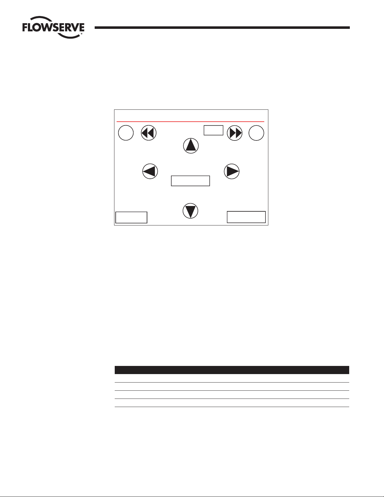
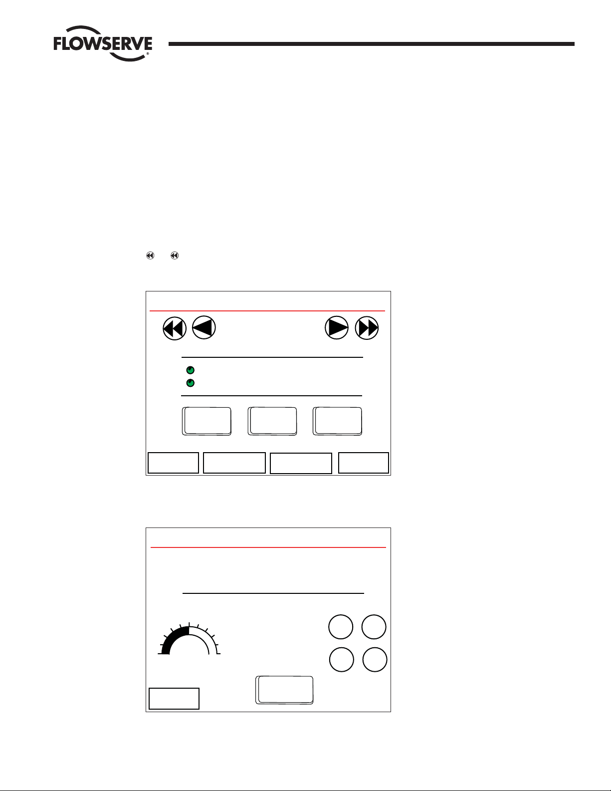
13 Control MOV
MOVs can be controlled from these screens. This includes opening, stopping, closing, and opening to a set position
(such as 50%).
Control MOV Page one (Figure 13-1) allows the user to open, stop, and close a MOV. Navigation between MOVs is
accomplished via the arrows at the top of the screen. The MOV Address and Tag indicate the MOV being controlled. The
and arrow buttons move the address in increments of 10.
Figure 13-1: Control MOV Page 1 screen
Control MOV page two (Figure 13-2) allows the user to set a MOV to an arbitrary position.
Figure 13-2: Control MOV Page 2 screen
Control MOV
MOV ID: 1
Tag MOVFU001
SET
POSITION
Percent Open Set Position
50%
Local Mode
50%
SHUT OPEN
+1
+10
-1
-10
<< Back
Control MOV
MOV Address 1
Tag MOVFU001
Channel A
Channel B Closed
OPEN
LOCAL MODE
STOP
CLOSE
<< Back
More >>
AR Relays
AS Relays
Page 62

62 DDC-100 Master Station II Installation and Operation Manual FCD LMAIM5001-00
Flow Control Division
Limitorque Actuation Systems
Figure 13-3: Control Auxillary Coils screen 1
Figure 13-4: Control Auxillary Coils screen 2
Control Aux. Coils
<< Back
MOV Address: 1 Tag MOVFU001
Note: Relays must be configured for
DDC Control at the MOV.
Feedback to User Inputs
is recommended
AS-1 AS-2 AS-3 AS-4
User #0 User #2 User #4 User #6
User #1 User #3 User #5 User #7
1
111
0
0
00
Control Aux. Coils
<< Back
MOV Address: 1 Tag MOVFU001
Note: Relays must be configured for
DDC Control at the MOV.
Feedback to User Inputs
is recommended
AS-1 AS-2 AS-3
User #0 User #2 User #4 User #6
User #1 User #3 User #5 User #7
1
11
0
00
Page 63

FCD LMAIM5001-00 DDC-100 Master Station II Installation and Operation Manual 63
Flow Control Division
Limitorque Actuation Systems
14 Emergency Shut Down
Should it be necessary to initiate an Emergency Shut Down of the networked MOVs, this can be accomplished by
accessing the Emergency Shut Down screen from the Main Menu (Figure 14-1).
Figure 14-1: Emergency Shut Down screen
Two options are available: Initiate a shutdown and Clear a shutdown. Once an Emergency Shut Down has completed and
is no longer necessary, the Emergency Shut Down state is cleared by pressing the Clear button.
When an Emergency Shut Down is Initiated, the Emergency Shut Down in Progress screen will be displayed
(Figure 14-2).
Figure 14-2: Emergency Shut Down in Progress screen
Emergency Shut Down In Progress
The Emergency Shut Down Procedure
has been initiated.
Main Menu
Procedure Complete
Emergency Shut Down ACTIVE
Pressing the red button will initiate
an Emergency Shut Down procedure
for the Network.
Once Initiated, the Emergency Shut
Down Procedure cannot be revoked.
Clear
Emergency
Shut Down
Initiate
Emergency
Shut Down
Cancel
Page 64

64 DDC-100 Master Station II Installation and Operation Manual FCD LMAIM5001-00
Flow Control Division
Limitorque Actuation Systems
When an Emergency Shut Down is Cleared, the Emergency Shut Down Termination in Progress screen will be displayed
(Figure 14-3).
Figure 14-3: Emergency Shut Down Termination screen
Emergency Shut Down Termination
The Emergency Shut Down Procedure
termination is in progress.
Main Menu
Procedure Complete
Page 65

FCD LMAIM5001-00 DDC-100 Master Station II Installation and Operation Manual 65
Flow Control Division
Limitorque Actuation Systems
15 Logger
The Logger allows the user to monitor the status of the network or communication traffic. The Logger Menu provides
two options: Data Analyzer and Network Status (Figure 15-1).
Figure 15-1: Logger Menu screen
Note: In a Hot Standby configuration, the Standby unit does not report logger functions.
The Data Analyzer screen allows the user to monitor communication traffic (Figure 15-2). Several monitoring options
are available:
Channel A: monitor communication on Channel A port
Channel B: monitor communication on Channel B port
DCS Port: monitor communication on DCS port
MNET Port: monitor communication on Modbus ethernet port
Activity Log Disabled: no logging
Logger
Data Analyzer
Logger Menu ACTIVE
<< Back
Page 66

66 DDC-100 Master Station II Installation and Operation Manual FCD LMAIM5001-00
Flow Control Division
Limitorque Actuation Systems
Figure 15-2: Data Analyzer Log screen
The Network Status Log screen (Figure 15-3) allows the user to log messages from the MOV network such as status
updates, fault information, and position. Only the last 10 messages are visible via the HMI, but all messages are
streamed to the printer port.
Figure 15-3: Network Status Log screen
Logger ACTIVE
10-28-03 16:15:50 MASTER MODE LOGGING
10-28-03 16:15:50 MOVFU001 1 NO COMMU
10-28-03 16:15:51 MOVFU002 2 NO COMMU
10-28-03 16:15:52 MOVFU003 3 NO COMMU
10-28-03 16:15:53 MOVFU004 4 NO COMMU
Start
<< Back
Data Analyzer Log ACTIVE
Channel A
Channel B
DCS Port
Modbus ENET
Activity Log Disabled
<< Back
Port Activity to Log
Page 67

FCD LMAIM5001-00 DDC-100 Master Station II Installation and Operation Manual 67
Flow Control Division
Limitorque Actuation Systems
Figure 15-4: Data Analyzer and Logger Concurrent Use Error screen
This screen appears if the user attempts to simultaneously activate both logger functions.
OK
When Data Analyzer is
Active, Logger is disabled
and when Logger is active,
Data Analyzer is disabled.
Message
Page 68

68 DDC-100 Master Station II Installation and Operation Manual FCD LMAIM5001-00
Flow Control Division
Limitorque Actuation Systems
This page is intentionally blank.
Page 69

FCD LMAIM5001-00 DDC-100 Master Station II Installation and Operation Manual 69
Flow Control Division
Limitorque Actuation Systems
16 Error Messages
Error messages appear when a user attempts to initiate a function out of sequence or while another process is operating.
Should a user attempt an unsafe task, the following error messages will be displayed.
Figure 16-1: Control Error
This screen will be displayed when control of a MOV is attempted on the Standby processor.
Figure 16-2: Configuration Error 1
This screen will be displayed when configuration of the Standby processor is attempted.
Configuration Error
Please use the ACTIVE unit to
configure the network.
This unit is configured
in STANDBY mode.
<< Back
Control Error
This unit is configured
in STANDBY mode.
Please use the ACTIVE unit to control
the network.
<< Back
Page 70

70 DDC-100 Master Station II Installation and Operation Manual FCD LMAIM5001-00
Flow Control Division
Limitorque Actuation Systems
Figure 16-3: Configuration Error 2
Torque information is viewed on the Active processor.
Figure 16-4: Inactivity Timeout
If the Master Station has not been used for a five minute period, the user will be logged out in 60 seconds.
Cancel
Due to inactivity, this
session will logoout in
60 seconds. Press the Cancel
button to continue this
session.
Inactivity Timeout
Configuration Error
Please use the ACTIVE unit to
view torque information.
This unit is configured
in STANDBY mode.
<< Back
Page 71

FCD LMAIM5001-00 DDC-100 Master Station II Installation and Operation Manual 71
Flow Control Division
Limitorque Actuation Systems
Figure 16-5: HMI Lockout Alert
If HMI control has been set to “Off”, this screen appears when the user attempts control from the Master Station touch
screen while the DCS is communicating with the Master Station.
Figure 16-6: HMI Control Verification screen
If HMI Control is turned OFF, the user will see an error screen if control is attempted while DCS or MNET traffic is
present.
HMI Control Verification
This unit is configured for
"HMI Control Disabled" during
DCS or MNET communications traffic.
Please wait while DCS and MNET
communications traffic is monitored.
OK
This operation cannot be
performed at this time,
since there is communication
traffic on the DCS port or
the MNET port.
Please try again.
Alert
Page 72

72 DDC-100 Master Station II Installation and Operation Manual FCD LMAIM5001-00
Flow Control Division
Limitorque Actuation Systems
This page is intentionally blank.
Page 73

FCD LMAIM5001-00 DDC-100 Master Station II Installation and Operation Manual 73
Flow Control Division
Limitorque Actuation Systems
17 Web Server Operation
Figure 17-1: Web navigation
Index View MOV Status Network Status
View Configuration Master Station Configuration
MOV Active/Inactive Tables
MOV Active/Inactive Tables
MOV Status
Network Status
MOV Status
Page 74

74 DDC-100 Master Station II Installation and Operation Manual FCD LMAIM5001-00
Flow Control Division
Limitorque Actuation Systems
Figure 17-2
Figure 17-3
To be supplied.
View Configuration
View MOV Status
Page 75

FCD LMAIM5001-00 DDC-100 Master Station II Installation and Operation Manual 75
Flow Control Division
Limitorque Actuation Systems
Figure 17-4
Key: = Red
= Green
= Yellow
=Blue
B
Y
G
R
MOV Status | MOVs 001-050 | Page 1 of 5 | Jump To Page: [1] [2] [3] [4] [5]
LEGEND No Communication Faults No MOV Fault
Channel A Fault Channel B Fault
Channel A and Channel B Fault MOV Fault
R
R
RY
GG
Refresh Data
MOV 001
MOV 002
MOV 003
MOV 004
MOV 005
MOV 006
MOV 007
MOV 008
MOV 009
MOV 010
MOV 011
MOV 012
MOV 013
MOV 014
MOV 015
MOV 016
MOV 017
MOV 018
MOV 019
MOV 020
MOV 021
MOV 022
MOV 023
MOV 024
MOV 025
MOV 026
MOV 027
MOV 028
MOV 029
MOV 030
MOV 031
MOV 032
MOV 033
MOV 034
MOV 035
MOV 036
MOV 037
MOV 038
MOV 039
MOV 040
MOV 041
MOV 042
MOV 043
MOV 044
MOV 045
MOV 046
MOV 047
MOV 048
MOV 049
MOV 050
RR
RR
RR
RR
RR
RR
RR
RR
RR
RR
RR
RR
RR
RR
RR
RR
RR
RR
RR
RR
RR
RR
RR
RR
RR
RR
RR
RR
RR
RR
RR
RR
RR
RR
RR
RR
RR
RR
RR
RR
RR
RR
RR
RR
RR
RR
RR
RR
RR
RR
Page 76

76 DDC-100 Master Station II Installation and Operation Manual FCD LMAIM5001-00
Flow Control Division
Limitorque Actuation Systems
Figure 17-4
Note: The setting shown above indicates default.
Master Station Confi guration
DCS Port Setup
DCS Address 1
DCS Baud Rate 9600
DCS Stop 1
DCS Parity None
DCS Electrical RS-232
DCS RTS ON 0
DCS RTS OFF 0
DCS HB Start Hot
DCS HMI Enabled Disable
Ethernet Port Setup
Enet ReadWrite Read Only
IP Address 192.168.0.100
Mask 255.255.255.0
Gateway 192.168.0.1
Standby IP Address 0.0.0.0
DCS Port / Ethernet port Data Table Parameters
DCS Register First Position
DCS Register Last Status
DCS 5/15 Coil Map ‘Close / Stop’ through ‘Open / Stop’
DCS Write Register 1
Network Setup
Network Baud Rate 9600
Network Timeout 500
Network Retries 1
Network Poll Mode LOOP
Network Propogation Delay 10
Network RTS Delay 10
First Confi gured Slave 1
Last Confi gured Slave 32
Total Active Slaves 32
MOV Active/Inactive Status
MOV 001-032
MOV 033-064
MOV 065-096
MOV 097-128
MOV 129-160
MOV 161-192
MOV 193-224
MOV 225-250
Page 77

FCD LMAIM5001-00 DDC-100 Master Station II Installation and Operation Manual 77
Flow Control Division
Limitorque Actuation Systems
Figure 17-4
Note: Gray lamps indicate an off or clear condition, while red lamps indicate an on or active condition.
<< Back to Status
MOV Status Detail | MOV Address 001 | [<<Prev MOV] [Next MOV>>]
MOV Tag Name: MOVFU001
Torque 0
Analog #1 0
Analog #2 0
Position 0
STATUS REGISTER
Opened
Closed
Stopped
Opening
Closing
Valve Jammed
Local Mode Selected
Combined Fault
Thermal Overload Fault
Fail De-Energize (UEC-3 ONLY)
Channel A Fault
Channel B Fault
Open Torque Switch Fault
Digital Output
Close Contactor
Open Contactor
AS-1
AS-2
AS-3
AS-4
AR-1, Opt
AR-2, Opt
AR-3, Opt
Digital Inputs 1 (Remote Mode Selected
Thermal Overload Fault
Open Torque Switch
Open Limit Switch
User 0, Terminal-21
User 1, Terminal-10
User 2, Terminal-9
User 3, Terminal-6
User 4, Terminal-7
User 5, Terminal-5
User 6, Terminal-23
User 7, Terminal-24
Digital Inputs 2
Analog In 1 Lost
Analog In 2 Lost
Network A/B Lost
DDC Bd. Present
I/O Opt Board Present
Phase Lost
Network Relay
Close Torque Switch Fault
Manual Operation
Phase Error
FAULT REGISTER
DIGITAL I/O
Phase(s) Missing
Phase Reversed
Network ESD is ON
Local ESD is ON
Unit Reset since last poll
Local Stop Selected
Opening in Local
Closing in Local
Refresh Status
Page 78

78 DDC-100 Master Station II Installation and Operation Manual FCD LMAIM5001-00
Flow Control Division
Limitorque Actuation Systems
This page is intentionally blank.
Page 79

FCD LMAIM5001-00 DDC-100 Master Station II Installation and Operation Manual 79
Flow Control Division
Limitorque Actuation Systems
18 Touch Panel Backlight
When the touch panel backlight burns out, the panel’s status LED will turn orange. The HMI is programmed for touch
operation to be disabled when the backlight burns out, which prevents the panel from sending commands to the PLC.
The touch panel unit uses a CCFL, long-life type backlight. The actual life of the backlight however, will vary depending on
the operating conditions, and replacement may be required. The backlight has a life of 30,000 hours (approximately 3.4
years), when the backlight is lit continuously (time required for brightness to fall to half its normal level).
Note: The touch panel screen saver feature is enabled to prevent continuous backlight operation for a longer
backlight life expectancy.
Pro-face part number: GP377L/S-BL00-MS
Warning
• To prevent an electric shock, be sure the touch panel’s power is disconnected from the power supply prior to
changing the backlight.
• When the power has just been turned OFF, the unit and backlight are still very hot. Be sure to use gloves to prevent
burns.
• The backlight is very fragile. Do not touch the glass tube directly or try to remove its power cord. If the glass tube
breaks, you may be injured.
Use the following steps to change the backlight. Be sure to use gloves.
1. Turn OFF power to the Master Station. Disconnect power.
2. Remove the power and serial cables from the touch panel and remove from the Master Station.
3. Unscrew the panel’s two (2) top face attachment screws.
4. Push down on the lock clip and open the panel’s rear cover.
5. Disconnect the backlight's power connector from the inverter board. Do not try to pull the cord out of the backlight.
6. Push the backlight's lock tab to the right to free the backlight, then pull it upwards and out of the unit.
Page 80

80 DDC-100 Master Station II Installation and Operation Manual FCD LMAIM5001-00
Flow Control Division
Limitorque Actuation Systems
80 DDC-100 Master Station II Installation and Operation Manual FCD LMAIM5001-00
7. Insert the new backlight and slide it into its slot until the lock tab can be clicked into place.
8. Attach the new backlight's power connector to the inverter board.
9. To replace the panel's rear cover, insert the cover’s guide tabs into the case's guide slots and close the cover. Be
sure that the rear cover connector and the front unit connector are correctly aligned
10. Install the panel's two (2) top face attachment screws.
11. Insert the touch panel into the Master Station by first attaching the power cables and serial cable, then install the
touch panel retaining clips.
12. Attach power to the Master Station and Turn ON the Master Station.
Page 81

FCD LMAIM5001-00 DDC-100 Master Station II Installation and Operation Manual 81
Flow Control Division
Limitorque Actuation Systems
FCD LMAIM5001-00 DDC-100 Master Station II Installation and Operation Manual 81
19 FTP Upload of MOV Tag Name Database
Using an FTP software application, connect to the Master Station TCP/IP port. Log onto the Master Station.
Page 82

82 DDC-100 Master Station II Installation and Operation Manual FCD LMAIM5001-00
This page is intentionally blank.
Flow Control Division
Limitorque Actuation Systems
Page 83

FCD LMAIM5001-00 DDC-100 Master Station II Installation and Operation Manual 83
20 How to Order Parts
To order parts or obtain further information about your Flowserve Limitorque Master Station II, contact your local
Limitorque distributor sales office, or:
FLOWSERVE CORPORATION
Limitorque Actuation Systems
5114 Woodall Road
P.O.Box 11318
Lynchburg, VA 24506-1318
Phone (434) 528-4400
Fax (434) 845-9736
To find the Limitorque distributor or sales office near you, go to http://www.limitorque.com
All inquiries or orders must be accompanied by the following information supplied on the actuator nameplate:
1. Master Station model
2. Order number
3. Serial number
Flow Control Division
Limitorque Actuation Systems
Page 84

84 DDC-100 Master Station II Installation and Operation Manual FCD LMAIM5001-00
This page is intentionally blank.
Flow Control Division
Limitorque Actuation Systems
Page 85

FCD LMAIM5001-00 DDC-100 Master Station II Installation and Operation Manual 85
21 Appendix
Figure A-1: Typical single Master Station II network diagram
Flow Control Division
Limitorque Actuation Systems
Page 86

86 DDC-100 Master Station II Installation and Operation Manual FCD LMAIM5001-00
Figure A-2: Typical hot standby Master Station II network diagram
Limitorque Actuation Systems
R
REVISION
RACK MOUNTABLE HOT
STANDB Y MASTER STAT ION
TITLE
DRAWING NO.
1ST ORDER NO.
APPROVED
CHECKED
DRAWN
DATE
DESCRIPTION
NO.
REV
SHEET
OF
DATE
DATE
DATE
15-493-0384-4
1 1
DKA 9/12/03
L-783 REV-A 4/26/93
MOV-3
SEE NOTE 5
A1* 15
A1 16
29 A2*
41 A2
MOV-2
SEE NOTE 5
A1* 15
A1 16
29 A2*
41 A2
MOV-1
SEE NOTE 5
A1* 15
A1 16
29 A2*
41 A2
MOV-248
SEE NOTE 5
A1* 15
A1 16
29 A2*
41 A2
MOV-249
SEE NOTE 5
A1* 15
A1 16
29 A2*
41 A2
MOV-250
SEE NOTE 5
A1* 15
A1 16
29 A2*
41 A2
MOV-4
SEE NOTE 5
A1* 15
A1 16
29 A2*
41 A2
MOV-247
SEE NOTE 5
A1* 15
A1 16
29 A2*
41 A2
N/C
N/C
N/C
-----
N/CN/C
N/CN/C
N/C
N/C
30
30
30
30
30303030
FRONT VIEW
REAR VIEW
TOP VIEW
ON/OFF SWITCH
110VAC POWER ENTRY
FUSE PROTECTION
EXT. 24VDC
MONITOR
FRONT VIEW
5.750
(146)
8.718
(221)
17.000
(432)
19.000
(483)
4X .278 x .406 OBLONG
(7) (10)
17.727
(450)
1.432
(36)
TERMINALS & CONNECTORS
HANDLES
o
l
FUSES
FUSES
l
o
ETHERNET
DO NOT USE
SINGLE
-+
24VDC
PROPER OPERATION
INSIDE OF UNIT FOR
INPUT ONLY
EXTERNAL 24VDC
MOVE JUMPERS ON
250 V
INPUT
POWER
~1.5A
100-240VAC
ON
OFF
FUSES
2 AMP
DCS
DATA *
GND
CHANNEL B
PRINTER / DEBUG
WITH 110-240VAC
OPTIONAL
DO NOT USE
HOT STANDBY
GND
DAT
A *
DAT
A
DCS
PRINTER / DEBUG
ON
OFF
~1.5A
INPUT
100-240VAC
250 V
POWER
2 AMP
FUSES
-+
24VDC
PROPER OPERATION
INSIDE OF UNIT FOR
INPUT ONLY
EXTERNAL 24VDC
MOVE JUMPERS ON
WITH 110-240VAC
CHANNEL A
DAT
A
NO SERVICEABLE PARTS INSIDE
MONITOR
GND (SEE NOTE 6)
MASTER STATION POWER REQUIREMENTS:
SINGLE: 110/240 VAC, 3.0 AMP (1.5 AMP PER CPU)
24 VDC, 4 AMP (2 AMP PER CPU)
JUMPER SELECTABLE
(DO NOT USE WITH 110-240 VAC CONNECTED)
TEMPERTURE RATING:
STORAGE: -20°C TO +60°C
OPERATIONAL: 0°C TO +45°C
PRINTER/DEBUG
SAME AS DCS PORT RS-232
DCS PORT
RS-232
DCD
RXD
TXD
DTR
GND
DSR
RTS
CTS
PIN
123456789
RS-422RS-485
TXD+
RXD+
GND
RXD-
TXD-
TXRXD+
GND
TXRXD-
ETHERNET PORT
MASTER STATION TO PC STRAIGHT-THRU
MASTER STATION TO HUB STRAIGHT-THRU
MASTER STATION TO PLC STRAIGHT-THRU
CABLE TYPE: DATA QUALITY CATEGORY 5 WITH
STANDARD RJ-45 CONNECTOR.
JUMPER CABLE MUST BE INSTALLED FROM MX-DDC TERMINAL BLOCK
(6) MASTER STATION MUST BE CONNECTED TO CLEAN EARTH-GROUND
(LESS THAN 5 OHMS) FOR ENHANCED NOISE REJECTION AND A
CLEAR/SAFE PATH FOR SURGE CURRENTS.
POLARITY AND LEVEL OF THE NETWORK'S DATA CONNECTION
CAN BE CHECKED BY MEASURING VOLTAGE BETWEEN DATA AND
DATA* TERMINALS. THIS VOLTAGE SHOULD BE GREATER THAN
+200mV DC WITH MASTER STATION NETWORK PORTS DISCONNECTED.
DATA TERMINAL IS POSITIVE WITH RESPECT TO DATA* TERMINAL.
DATA TERMINAL IS POSITIVE WITH RESPECT TO DATA* TERMINAL
ACTUATOR, CONTACT ENGINEERING FOR ALTERNATIVE EARTH GROUND
IF LOW IMPEDANCE EARTH GROUND IS NOT AVAILABLE AT EACH
NOISE REJECTION AND PROVIDES A CLEAR/SAFE PATH FOR SURGE
A CLEAN EARTH-GROUND CONNECTION (LESS THAN 5 OHMS) ENHANCES
(5) EARTH GROUND: GROUND ROD OR CONNECTION TO GROUND ROD.
(4) BELDEN 3105A, 9841, OR 3074F SHIELDED TWISTED PAIR CABLE IS
(3) CONNECTIONS SHOWN ARE TYPICAL. THE NUMBER OF MOV'S SHOWN
(2) CORRECT POLARITY FOR FIELD UNIT AND MASTER STATION CONNECTIONS
(1) MASTER STATION AND FIELD UNITS REQUIRE EXTERNAL POWER SUPPLY.
PIN 30 TO EARTH-GROUND.
DIAGNOSTIC NOTE:
---------------
- SHIELD
30 - SURGE PROTECTION
N/C - NO CONNECTION
16 - DATA A1
15 - DATA A1*
41 - DATA A2
29 - DATA A2*
------------------
EARTH GROUND NOTE:
SURGE PROTECTION STRATEGIES.
CURRENTS.
RECOMMENDED.
MAY NOT INDICATE TRUE SYSTEM SIZE.
IS NECESSARY FOR PROPER OPERATION.
MOV - MOTOR OPERATED VALVE
_______
LEGEND:
_____
NOTES:
Flow Control Division
Limitorque Actuation Systems
Page 87

FCD LMAIM5001-00 DDC-100 Master Station II Installation and Operation Manual 87
Flow Control Division
Limitorque Actuation Systems
Page 88

Flow Control Division
Limitorque Actuation Systems
Limitorque
5114 Woodall Road, P.O. Box 11318
Lynchburg, VA 24506-1318
Phone (434) 528-4400, Fax (434) 845-9736
http://www.limitorque.com
Limitorque
Abex Road
Newbury
Berkshire, RG14 5EY
England
Phone 44-1-635-46999
Fax 44-1-635-36034
Limitorque Nippon Gear Co., Ltd.
Asahi-Seimei Bldg. 4th Floor
1-11-11 Kita-Saiwai, Nishi-Ku
Yokohama-Shi, (220-0004)
Japan
Phone 81-45-326-2065
Fax 81-45-320-5962
Limitorque India, Ltd.
15/4, Mile Stone
Mathura Road
Faridabad 121002
India
Phone 91-129-2276586
Fax 91-129-2277135
Flowserve Australia, Pty. Ltd.
14 Dalmore Drive
Scoresby, Victoria 3179
Australia
Phone: 61 3 9759 3300
Facsimile: 61 3 9759 3301
Limitorque Asia, Pte., Ltd.
12, Tuas Avenue 20
Singapore 638824
Phone 65-6868-4628
Fax 65-6862-4940
(Replaces 435-11000)
© 2004 Flowserve Corporation, Irving, Texas, USA. Flowserve and Limitorque are registered trademarks of Flowserve Corporation. FCD LMAIM5001-00 Printed in USA.
Flowserve Corporation has established industry leadership in the design and manufacture of its products. When properly selected, this Flowserve product is designed to
perform its intended function safely during its useful life. However, the purchaser or user of Flowserve products should be aware that Flowserve products might be used in
numerous applications under a wide variety of industrial service conditions. Although Flowserve can (and often does) provide general guidelines, it cannot provide specific
data and warnings for all possible applications. The purchaser/user must therefore assume the ultimate responsibility for the proper sizing and selection, installation,
operation, and maintenance of Flowserve products. The purchaser/user should read and understand the Installation Operation Maintenance (IOM) instructions included with
the product, and train its employees and contractors in the safe use of Flowserve products in connection with the specific application.
While the information and specifications contained in this literature are believed to be accurate, they are supplied for informative purposes only and should not be considered certified or as a guarantee of satisfactory results by reliance thereon. Nothing contained herein is to be construed as a warranty or guarantee, express or implied,
regarding any matter with respect to this product. Because Flowserve is continually improving and upgrading its product design, the specifications, dimensions and information contained herein are subject to change without notice. Should any question arise concerning these provisions, the purchaser/user should contact Flowserve
Corporation at any one of its worldwide operations or offices.
FLOWSERVE CORPORATION
FLOW CONTROL DIVISION
Limitorque Actuation Systems
5114 Woodall Road
P.O. Box 11318
Lynchburg, VA 24506-1318
Phone: 434 528 4400
Facsimile: 434 845 9736
www.limitorque.com
For more information about Flowserve Corporation, visit www.flowserve.com or call USA 1 800 225 6989.
 Loading...