

Page 1
USER INSTRUCTIONS
Installation
Operation
Maintenance
D30 Compact
Digital Positioner
FCD PMENIM0030-01-A5 – 05/18
Page 2

D30 Digital Positioner FCD PMENIM0030-01-A5 – 05/18
2
Contents
1. Introduction 3
2. Storage 6
3. Installation 7
4. Control 17
5. Maintenance/service 34
6. Trouble shooting 39
7. Technical data 40
8. Dimensions 42
9. Spare parts 43
Page 3

D30 Digital Positioner FCD PMENIM0030-01-A5 – 05/18
3
1. Introduction
The D30 is a digital positioner designed
primarily for controlling modulating valves. The
positioner can be used with single or double
acting actuators with either rotary or linear
movement.
The D30 can be equipped with modules for
limit switches and pressure gauges. Pressure
sensors can be installed to offer advanced
diagnostics.
The modules can be factory assembled before
delivery or fitted later.
The modules for limit switches can contain one
of the following:
• Two mechanical contacts
• Two proximity switches
• Two inductive sensors
See page 12 for more options available
Page 4

D30 Digital Positioner FCD PMENIM0030-01-A5 – 05/18
4
Warning!
Special Conditions for Safe Use
The enclosure of PMV D30 Intrinsically safe version is made of aluminium and any impact
or friction caused by external objects shall be avoided in the application.
The surface area of the plastic parts on the cover exceeds the limits specified in EN
60079-0 for II 1G (EPL Ga) for gas group IIC and intensive rubbing or brush charging
should be avoided when used in an IIC explosive atmosphere.
The cable connection of the Remote Unit with the D30 – unit shall be type A or B in
accordance with EN 60079-25. The cable must be adequately mechanically protected in
all instances and have a temperature rating for the ambient temperature range at the site.
Control Drawing D4-086C contains the parameters for intrinsically safety.
The intrinsic safe circuits D30 is insulated from earth and complies with the dielectric
strength test of 500 VAC.
In a hazardous environment where there is a risk of explosion, electrical connections
must comply with the relevant regulations.
Do not disconnect equipment unless area is known to be non-hazardous. or; read,
understand and adhere to the manufacturer’s live maintenance procedures. To prevent
ignition of flammable or combustible atmospheres, disconnect power before servicing,
Substitutions of components may impair suitability for hazardous (classified) locations.
When installing PMV D30 Intrinsically safe unit always consult drawing D4-086C
Page 5

D30 Digital Positioner FCD PMENIM0030-01-A5 – 05/18
5
Maintenance Service
Warning!
When upgrading electronically parts inside a PMV positioner approved for installation in
Hazardous locations special procedures apply, permission from PMV/Flowserve is required
prior to the start of work. Please contact a Flowserve office for information regarding proper
procedures www.pmv.nu or infopmv@flowserve.com
-Always turn off the air and electrical supplies before starting any work.
Safety instruction
Read the safety instructions in this manual carefully before using the product. The
installation, operation, and maintenance of the product must be done by staff with the
necessary training and experience. If any questions arise during installation, contact the
supplier/sales office before continuing work.
Warning
The valve can open or close very quickly when in operation and, if handled incorrectly, it may
cause damages. There may also be unintentional effects due to it fully opening or shutting
off the flow in the process pipe. Please note the following:
• If the input signal fails or is switched off, the valve operates quickly to its default position.
• If the compressed air supply fails or is turned off, rapid movements can occur.
• The valve is not controlled by the input signals when in the Out of Service mode. It will
open/close in the event of an internal or external leak.
• If a high value is set for Cut off, fast movements can occur.
• When the valve is controlled in the Manual mode, the valve can operates quickly.
• Incorrect settings can cause self-oscillation, which can lead to damage.
Important
• Always turn off the compressed air supply before removing or disconnecting the air
supply connection or the integral filter. Remove or disconnect with care as air connection
”C-” is still under pressure even after the air supply is turned off.
• Always work in an ESD (Emergency Discharge) protected area when servicing the Printed
circuit boards (PCB´s). Make sure the input signal is switched off.
• The air supply must be free from moisture, water, oil and particles according to DIN/ISO
8573-1-2001 3.2.3.
Page 6

D30 Digital Positioner FCD PMENIM0030-01-A5 – 05/18
6
2. Storage
General
The D30 positioner is a precision instrument.
Therefore it is essential that it is handled and
stored in the correct way. Always follow the
instructions in this IOM!
Note: As soon as the positioner is connected
and started, internal air venting will provide
protection against corrosion and prevent
the ingress of moisture. For this reason, the
air supply pressure should always be kept
on unless repair/maintenance work of the
positioner, actuator or valve equipment is in
progress.
Keep the cover mounted on the positioner and
replace any damaged window.
Storage indoors
Store the positioner in its original packaging.
The storage environment must be clean, dry,
and cool (15 to 26°C, 59 to 79°F).
Storage outdoors or for a longer period
If the positioner must be stored outdoors,
it is important that all the cover screws are
tightened and that all open ports/connections
are properly sealed and/or plugged.
The red shipping plugs are not intended as a
permanent outdoor plug. The unit should be
packed with a desiccant (silica gel) in a plastic
bag or similar, covered with plastic, and not
exposed to sunlight, rain, or snow.
This is also applicable for long-term storage
(more than 1 month) and for long transport by
sea.
Storage in a warm place
When the positioner is stored - without air
supply pressure applied - in a warm place with
a high relative humidity and is subjected to
daily temperature variations, the air inside the
unit will expand and contract.
This means that air from outside the unit may
be drawn into the positioner. Depending on the
temperature variations, relative humidity, and
other factors, condensation and corrosion can
occur inside the unit, which in turn can give rise
to functional disorders or a failure.
Page 7

D30 Digital Positioner FCD PMENIM0030-01-A5 – 05/18
7
3. Installation
Removal of cover
General purpose / Intrinsically safe
Remove cover by first loosening the screw 1
and then the two screws 2.
To install cover, first tighten the screw 1, then
the two screws 2.
Tighten to 1.5 Nm ± 15%.
Supply air should meet requirements specified
on page 5. A coalescing filter/regulator
should be installed in front of the supply air
connection. Now connect the air supply to the
filter, which is connected to the D30 positioner.
Tubing
It is recommended to use tubes with a
minimum inner diameter of Ø 6 mm (¼”).
Air supply requirements
Poor quality air supply is the main cause of
problems in pneumatic systems.
The air supply must be free from moisture,
water, oil and particles and delivered @ 1.4-8
barg (20-115 psi)
Standard: DIN/ISO 8573-1-2001 3.2.3
Filtered to 5 Micron, dew point -40°C/F
Oil 1mg/m³ (0,83 ppm by weight)
The air must come from a refrigeration dried
supply or be treated in such a way that its dew
point is at least 10°C (18°F) below the lowest
expected ambient temperature.
To ensure a stable and problem-free air supply,
we recommend the installation of a
coalescing filter/regulator <5µ as close to the
positioner as possible.
Before the air supply is connected to the
positioner, we recommend the hose is
opened freely for 2 to 3 minutes to allow any
contamination to be blown out. Direct the air
jet into a large paper bag to trap any water, oil,
or other foreign materials. If this indicates that
the air system is contaminated, it should be
properly cleaned before continuing.
2
1
WARNING! Do not direct the open air jet
towards people or objects because it may
cause personal injury or damage.
Page 8

D30 Digital Positioner FCD PMENIM0030-01-A5 – 05/18
8
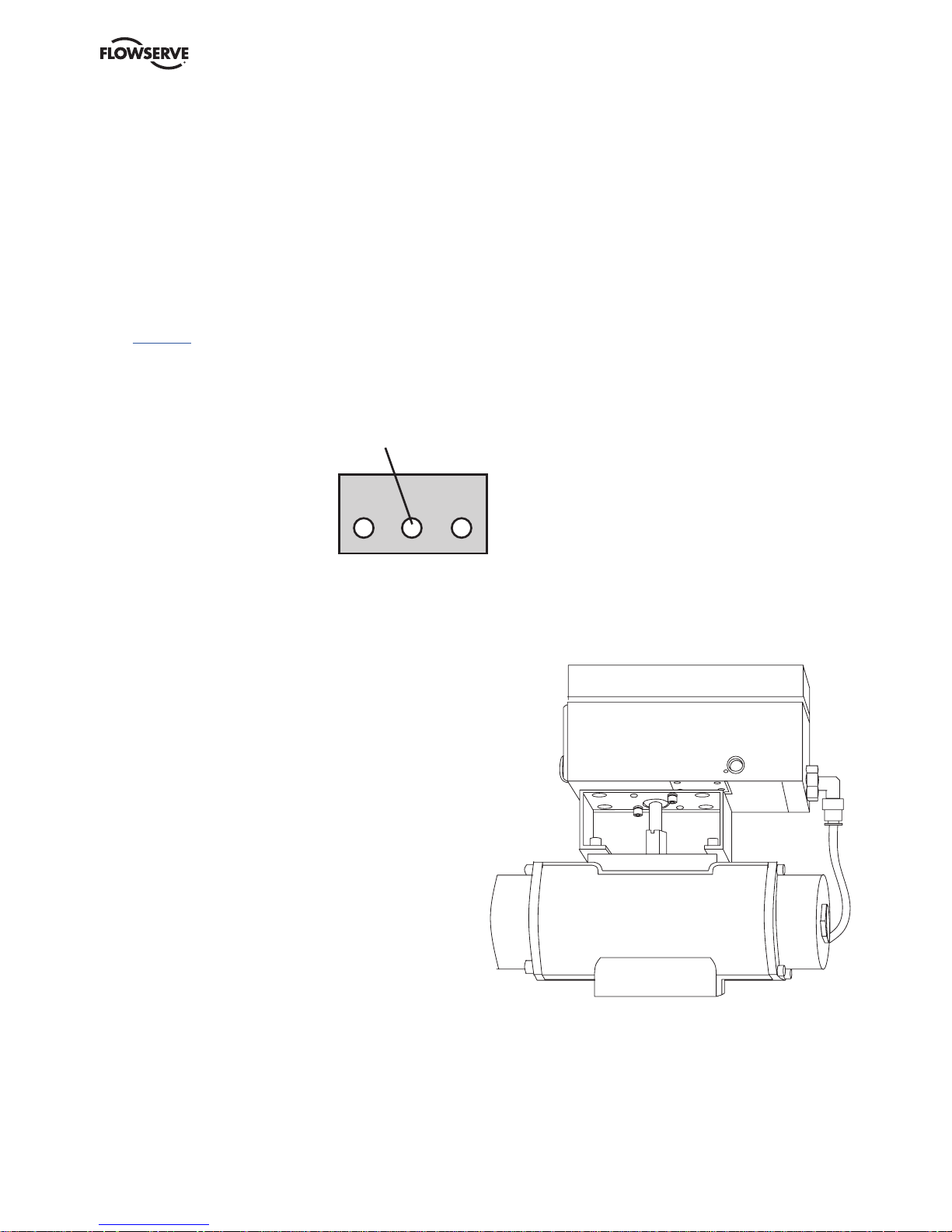
Mounting
Note: If the positioner is installed in a
hazardous environment, it must be of a type
approved for this purpose.
All versions of the D30 positioner have an ISO
F05 footprint. The holes are used to attach the
D30 to the mounting bracket B. Please contact
PMV or your local distributor representative
with actuator specifics for the proper mounting
bracket and hardware.
The spindle shaft S09 can be changed to suit
various actuators in question by the use of
adaptors.
It is important that the positioner’s spindle
shaft and the lever arms, that transfer the
actuator movements, are correctly mounted.
Any tension between these parts can cause
incorrect operation and abnormal wear.
Spindle shafts
S39 S09
AAssembly examples
Rotary movement Linear movement
C
B
S23
S9
0,354
9
0,079
2
S39
23,2
0,913
0,394
10
S23
5
0,197
4
0,157
0,957
24,3
M3 8
0,236
6
0,394
10
0,354
9
0,189
4,80
M8x1
0,091
2,30
Note: There are many spindle options available depending on the actuator. Please contact your local PMV
supplier for all options available.
Page 9
D30 Digital Positioner FCD PMENIM0030-01-A5 – 05/18
9
Connections
Air:
Port S Supply air, 1.4-8 barg (20-115 psi)
Port C+ Connection to actuator, opening
Port C- Connection to actuator, closing
(only for double action)
Plug for single action, see below
Electrical connection
See page 12.
Dimensions
Air connections: ¼” NPT alt. G ¼”
Electrical connection: M20 x 1.5 alt. NPT ½”
Loctite 577 or equivalent is recommended as a
sealant.
S
Must be plugged when converting
to single action function.
External air
Connection
C+ C-
Rotary actuators VDI/VDE 3485
(Namur)
Fit bracket on actuator and secure
with 4 x screws.
Mount positioner to bracket. Secure with 4 x M6
screws using 2.5 Nm (1.8 lb ft) torque.
Install tubing between actuator and positioner.
Page 10

D30 Digital Positioner FCD PMENIM0030-01-A5 – 05/18
10
Single acting positioner, Direct function
Actuator with closing spring
When the control signal increases, the pressure C+
to the actuator is increased. The valve stem moves
upward and rotates the positioner spindle counter-
clockwise. When the control signal drops to zero,
C+ is vented and the valve closes.
Reverse function
C+
CS
C+
CS
C+
CS
Actuator with opening spring
When the control signal increases the pressure
C+ to the actuator is increased. The valve stem
moves downward and the positioner spindle rotates
clockwise. When the control signal drops to zero,
C+ is vented and the valve opens.
Double acting positioner, Direct function
Double acting actuator
When the control signal increases, the pressure
C+ to the actuator is increased. The valve stem is
pressed upward and rotates the positioner
spindle counter-clockwise. When the control signal
is reduced, the pressure C- to the
actuator increases and the valve spindle is pressed
downward. If the control signal
disappears, the pressure goes to C-, C+ vents, and
the valve closes.
Page 11

D30 Digital Positioner FCD PMENIM0030-01-A5 – 05/18
11
Gauge block
Gauge blocks are available for D30s with ¼” G
or ¼” NPT air connections. To install, ensure
seals are aligned, then use 3 Nm (2.2 lb ft) of
torque when fastening the gauge block to the
positioner using the two screws supplied with
the kit.
Page 12
D30 Digital Positioner FCD PMENIM0030-01-A5 – 05/18
12
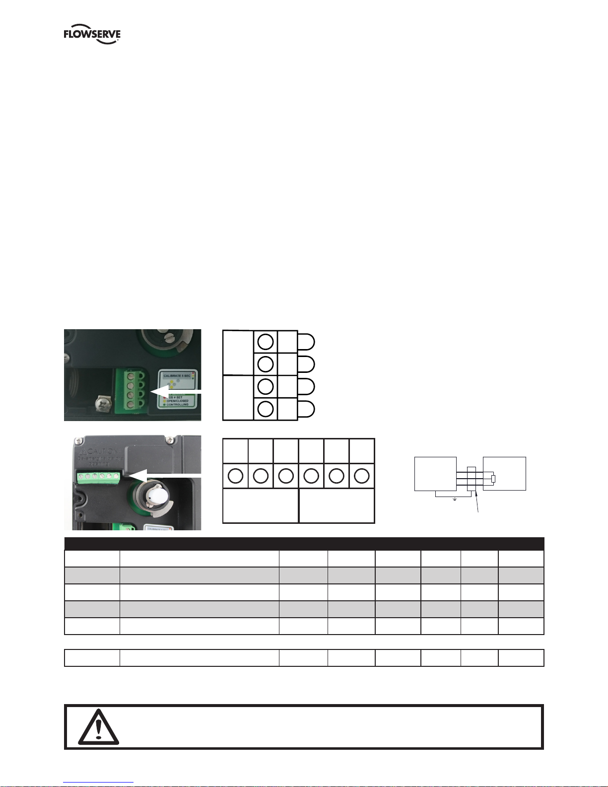
Electrical connections
Terminal block diagram for the D30.
The terminal block for the positioner is
accessible when the aluminum cover is
removed.
The D30 digital positioner has been designed to
operate correctly in electromagnetic (EM) fields
found in typical industrial environments. Care
should be taken to prevent the positioner from
being used in environments with
excessively high EM field strengths (greater
than 10 V/m). Portable EM devices such as
hand-held two-way radios should not be used
within 30 cm of the device.
Ensure proper wiring and shielding techniques
of the control lines, and route control lines
away from electro-magnetic sources that may
cause unwanted noise.
An electromagnetic line filter can be used to
further eliminate noise.
In the event of a severe electrostatic discharge
near the positioner, the device should be
inspected to ensure correct operability. It may
be necessary to recalibrate the D30 positioner
to restore operation.
1 2 3 4
+ -
4-20mA
in
+ -
4-20mA
out
1. Input signal + 4-20mA DC
2. Input signal - 4-20mA DC
3. 4-20mA + Feedback 13-28 VDC
4. 4-20mA - Feedback 13-28 VDC
Lower
Switch
Upper
Switch
6 7 8 9
10
5
switch es or re mote
Optional board
5 6 7 8 9 10
POSITIONER
Potentiometer
or F5 unit
HAZARDEOU S AREA
8
9
10
Po:0.38W
According
Safety
Barrier
5 or 8
6 or 9
7 or10
Switch
Ui,li,Pi and Li
to table
Scheduled drawing
No modification perm ited without
reference to Notif ied Body
OUT
1 2 3 4
+ -
INPUT
SIGNAL
+ -
4-20mA
Option
D30 Model code
Position B designates certification
3+
Remote Unit
Safety
1+
2-
Ci ≤ 11.3 nF
Substitutions of components may impair suitability for hazardous (classified) locations.
less than 10m or 30 feet
switches
(Position B; B=A or B=E) AND
Reqires shielded cable
4-20mA input signal
HAZARDEOUS AREA UNCLASISIFIED AREA
D30 series terminal configuration
4-20mA Output signal
(Position J; J=4 or J=5)
(Unit has no switches)
Pin 3 and 4
Pin 1 and 2
HAZARDEOUS AREA UNCLASISIFIED AREA
Position H 13 designates Indicator type
Position K designates switch type
(Wher x any character)
Position GG; GG=Rx
Position J designates comunication protokoll
HAZARDEOUS AREA UNCLASISIFIED AREA
or; read, understand and adhere to the manufacturer's live maintenance procedures.
(Position B; B=A or B=E) AND
4-
To prevent ignition of flammable or combustible atmospheres, disconnect power before ser vicing,
Do not disconnect equipment unles s area is known to be non-hazardous.
(Position K; K≠X)
(Position J; J=4 or J=5) AND
Safety
Barrier
is not suitable for Da,Db or Dc enviroments
Warnings:
Barrier
Li ≤ 11.3 µH
If Pos H 13 =D (dome indicator) then product
POSITIONER
Ui ≤ 28 V
Ii ≤ 93 mA
Pi ≤ 653 mW
POSITIONER
Ui ≤ 28 V
Ii ≤ 93 mA
Pi ≤ 653 mW
Ci ≤ 22 nF
Li ≤ 11.3 µH
-
ANNOTATIONDIMENSIONMATERIALDESCRIPTION
HOLE TOL. UNSPECIFIED TOLERANCES ACCORDING TO: SURFACE
PROJECTION EUROPA
-
Control Drawing
1 2 3 4 5 6 7 8 9 10 11 12 13 14 15 16 17 18 19
A A A B C D E - F G G H H H - I J K L M N
model code positi on
K
model code posit ion
B
A E
Note SWIT CH Type Ci nF Li uH U i V I i mA Pi mW
Min .
temp
T4 (*) T5 (* ) T6 (* )
T
(III C Da)
ATE X iaIECEx
ia
5
2 SJ2-SN NAMUR 30 100 16 25 34 -40 96 68 56 100 Ga ,Da Ga ,Da
6
1 SJ2-N NAMUR 30 100 16 25 34 -25 96 68 56 100 Ga ,Da Ga ,Da
7
1 SC2-N0-GN NAMUR 150 150 16 25 34 -25 95 67 55 100 Ga ,Da Ga ,Da
8
1 SC2-N0-YE NAMUR 150 150 16 25 34 -25 95 67 55 100 Ga ,Da Ga ,Da
G
Mechanical sw itch gold Mec. 1 1 28 45 315 -40 78 60 45 Ga ,Da Ga ,Da
N
3 NJ 2-V3-N NAMUR 40 50 16 25 34 -25 96 68 56 100 Ga Ga
P
Hamli n Proxim ity Reed 1 1 28 45 315 -40 80 - - Ga ,Da Ga ,Da
S
Mechanical sw itch Mec. 1 1 28 45 315 -40 78 60 45 Ga ,Da Ga ,Da
U
3 NCN4-V3-N0 NAMUR 100 100 16 25 34 -25 73 88 100 100 Ga Ga
not e 1 Higher Ui,Li and Pi w ith l ower a mbient temeratures a re alow ed see Certificat e PTB 99 ATEX 2219 X or IECEx PTB 11.0091X
not e 2 Higher Ui,Li and Pi w ith l ower a mbient temeratures a re alow ed see Certificate PTB 00 ATEX 2049 X or IEC Ex PTB 11.0092X
not e 3 Higher Ui,Li and Pi w ith l ower a mbient temeratures a re alow ed see Certificate PTB 00 ATEX 2032 X or IEC Ex PTB 11.0021X
Remote Unit
Order code Switch 5 6 7 8 9 10
S Limit switches Mechanical SPDT NO NC Com NO NC Com
N Namur V3 type sensor, P&F NJ2-V3-N - + Not Used - + Not Used
P Limit switches Proximity SPDT NO NC Com NO NC Com
5 Slot type Namur sensor, P&F SJ2-SN - + Not Used - + Not Used
6 Slot type Namur sensor, P&F SJ2-N - + Not Used - + Not Used
RM Remote Board Not Used Not Used Not Used CCW RA CW
Warning! In a hazardous environment where there is a risk of explosion, electrical
connections must comply with the relevant regulations.
Page 13

D30 Digital Positioner FCD PMENIM0030-01-A5 – 05/18
13
Limit switch calibration
• Losen screws (1) and adjust cams.
• Adjust lower cam first and then upper cam
• Tighten screws (1)
Aproximat switching plase for reed switches
1
Page 14

D30 Digital Positioner FCD PMENIM0030-01-A5 – 05/18
14
Feedback option (cont.)
Calibration of the 4-20 mA transmitter
Connecting the switches/sensors
switche s or rem ote
Optional board
5 6 7 8 9 10
POSITIONER
Potentiometer
or F5 unit
HAZARDEOUS A REA
8
9
10
Po:0.38W
According
Safety
Barrier
5 or 8
6 or 9
7 or10
Switch
Ui,li,Pi and Li
to table
Scheduled drawing
No modification permited w ithout
reference to Notified Body
OUT
1 2 3 4
+ INPUT
SIGNAL
+ -
4-20mA
Option
D30 Model code
Position B designates certification
3+
Remote Unit
Safety
1+
2-
Ci ≤ 11.3 nF
Substitutions of components may im pair suitability for hazardous (classified) locations.
less than 10m or 30 feet
switches
(Position B; B=A or B=E) AN D
Reqires shielded cable
F5ISxx-xxx-P27-xxPVxxx-x
4-20mA input signal
HAZARDEOUS AREA UNCLASISIFIED AREA
D30 series terminal configuratio n
4-20mA Output signal
(Position J; J=4 or J=5)
Terminal 8-9 upper switch
(Unit has no switches)
Pin 3 and 4
Pin 1 and 2
HAZARDEOUS AREA UNCLASISIFIED AREA
Position H 13 designates Indicator t ype
Position K designates switch type
(Wher x any character)
Terminal 5-7 lower switch
Position GG; GG=Rx
Position J designates comunication prot okoll
HAZARDEOUS AREA UNCLASISIFIED AREA
or; read, understand and adher e to the manufacturer's live maintenance procedures.
terminal 7 and 10 not used for Na mur Switches
(Position B; B=A or B=E) AN D
4-
F5ISxx-xxx-POT-xxPVxxx-x
Allowed F5 units are:
To prevent ignition of flammable or combust ible atmospheres, disconnect power before servicing,
Do not disconnect equipment unless area is known to be non-hazardous.
(Position K; K≠X)
(Position J; J=4 or J=5) AND
F5ISxx-xxx-P18-xxPVxxx-x
Safety
Barrier
is not suitable for Da,Db or Dc enviroments
Warnings:
Barrier
Li ≤ 11.3 µH
If Pos H 13 =D (dome indi cator) then product
POSITIONER
Ui ≤ 28 V
Ii ≤ 93 mA
Pi ≤ 653 mW
Potentiometer unit needs an ap ropriate and compatible
Certification for the Hazaredu s area
POSITIONER
Ui ≤ 28 V
Ii ≤ 93 mA
Pi ≤ 653 mW
Ci ≤ 22 nF
Li ≤ 11.3 µH
-
PMV Positioners
-
2017-12-11
imparted to a third party nor be us ed for any unauthorized purpose. Contrave ntion will be prosecuted
DRAWING NO.
DRW BY Rev. SCALE DATE
ANNOTATIONDIMENSIONMATERIALDESCRIPTION
HOLE TOL. UNSPE CIFIED TOLERANCES ACCORDING TO: SURFACE
-
PROJECTION EUROPA
-
PMV Automation AB
Control Drawing
KORTA GATAN 9 SE-17 1 54 SOLNA SWEDEN - Tel:+46(0)8 555 106 00-Fax:+46(0)8 555 106 01 - www.pmv.nu
-
D4-086C
LRW
-
D30
This document must not be copi ed without our written permissi on and the contents there of must not be
0
1 2 3 4 5 6 7 8 9 10 11 12 13 14 15 16 17 18 19
A A A B C D E - F G G H H H - I J K L M N
model code po sition
K
model code po sition
B
A E
Note S WITCH Type Ci nF Li u H U i V I i mA Pi mW
Min .
temp
T4 (*) T5 (* ) T 6 (*)
T
(IIIC Da)
ATE X iaIECEx
ia
5
2 SJ2-SN NAMUR 30 100 16 25 34 -40 96 68 56 100 Ga ,Da Ga ,Da
6
1 SJ2-N NAMUR 30 100 16 25 34 -25 96 68 56 100 Ga ,Da Ga ,Da
7
1 SC2-N0-GN NAMUR 150 1 50 16 25 34 -25 95 67 55 10 0 Ga ,Da Ga ,Da
8
1 SC2-N0-YE NAMUR 150 1 50 16 25 34 -25 95 67 55 10 0 Ga ,Da Ga ,Da
G
Mechanical switch go ld Mec. 1 1 28 45 315 -40 78 60 45 Ga ,Da Ga ,Da
N
3 NJ2-V 3-N NAMUR 40 50 16 25 34 -25 96 68 56 100 Ga Ga
P
Hamlin Proximity Reed 1 1 28 45 315 -40 80 - - Ga ,Da Ga ,Da
S
Mechanical switch Me c. 1 1 28 45 315 -40 78 60 45 Ga ,Da Ga ,Da
U
3 NCN4-V3-N0 N AMUR 100 100 16 25 34 -25 73 88 100 100 Ga Ga
not e 1 Higher Ui, Li and Pi w ith low er ambient temerat ures are alowed see Certifi cate PTB 99 ATEX 2219 X or IECEx PTB 11.0091X
not e 2 Higher Ui, Li and Pi w ith low er ambient temerat ures are alowed see Certificat e PTB 00 ATEX 2049 X or IECEx P TB 11.0092X
not e 3 Higher Ui, Li and Pi w ith low er ambient temerat ures are alowed see Certificat e PTB 00 ATEX 2032 X or IECEx P TB 11.0021X
Page 15

D30 Digital Positioner FCD PMENIM0030-01-A5 – 05/18
15
Type sign example
FFH PA
REVISIONS
S/N:
PMV Automation AB
FLOWSERVE, SWEDEN
Temp Range:
Software:
Solna, Sweden
www.flowserve.com
Input Pressure:
Input Signal:
Prod.year:
Ingress protection rati ng
Logo type
Serial.no
Area for switch type
and terminals
Bar Code
Special note
Applicable Certificat
Area for markings, Ex ratings
and associated warnings if applicable
Type and model
H FFPA
No modification permitted without reference
to the Notified Body.
Schedule drawing
Zebra Z-Xtreme 4000
0
2017-11-06
imparted to a third part y nor be used for any unauthor ized purpose. Contravention wi ll be prosecuted
2:1
D4-090C-A
LRW
D30
PMV Positioner
This document must not be copied without our written perm ission and the contents ther e of must not be
Sceduled Drawing
PROJECTION EUROPA
PMV Automation AB
DRAWING NO.
DRW BY Rev.
SCALE
DATE
ANNOTATIONDIMENSIONMATERIALDESCRIPTION
HOLE TOL. UNS PECIFIED TOLERANCES ACCORDING TO: SURFACE
KORTA GATAN 9 SE-171 54 SOLNA SWEDEN - T el:+46(0)8 555 106 00 - www.pmv.nu
D4-090C-2
REVISIONS
REV. DESCRIPTION DATE APPROVED
0470
INTRINSICALLY SAFE
Exia: When installed in accordance with installation
drawing: D4-086C.
WARNING! Avoid intensive rubbing or brush charging of
plastic parts in IIC explosive atmosphere.
Model code Certif ication declaration
DxxAxxxx-xxxxxz-xxyxxx
where z ≠ D and ( y≠N or y≠U)
II 1G Ex ia IIC T4 Ta -40 C to 85 C Ga
II 1D Ex ia IIIC T80 C Da
DxxAxxxx-xxxxxD-xxxxxx or
DxxAxxxx-xxxxxx-xxyxxx
where y=N or y=U
II 1 G Ex ia IIC T4 Ta -40 C to 85 C Ga
D30 Model code
Certification declaration
Serienummer
S/N:
www.flowserve.com
Input Signal:
and terminals
Area for switch type
Prod.year:
Bar Code
FLOWSERVE, SWEDEN
PMV Automation AB
IP 66
Area for logotype
Område för logotype
Software:
Type and model
Typbeteckning och modellkod
Streckkod
Solna, Sweden
Presafe 17 ATEX 11142X
Temp Range:
Special note
Serial.no:
Input Pressure:
NEMA Type
ingressprotection
60
40
1 2 3 4 5 6 7 8 9 10 11 12 13 14 15 16 17 18 19
A A A B C D E - F G G H H H - I J K L M N
H FFPA
No modification permitted without reference
to the Notified Body.
Scheduled drawing
and terminals
Prod.year:
Area for switch type
Bar Code
Special note
www.flowserve.com
S/N:
Serial.no:
FLOWSERVE, SWEDEN
PMV Automation AB
IP 66
Input Signal:
Temp Range:
Type and model
Typbeteckning och modellkod
Area for logotype
Område för logotype
Software:
Streckkod
Solna, Sweden
Serienummer
IECEx PRE 17.0046X
Certification declaration
Input Pressure:
NEMA Type
ingressprotection
60
40
D4-090C-6
REVISIONS
REV. DESCRIPTION DATE APPROVED
0470
INTRINSICALLY SAFE
Exia: When installed in accordance with installation
drawing: D4-086C.
WARNING! Avoid intensive rubbing or brush charging of
plastic parts in IIC explosive atmosphere.
Model code Certif ication declaration
DxxExxxx-xxxxxz-xxyxxx
where z ≠ D and ( y≠N or y≠U)
II 1G Ex ia IIC T4 Ta -40 C to 85 C Ga
II 1D Ex ia IIIC T80 C Da
DxxExxxx-xxxxxD-xxxxxx or
DxxExxxx-xxxxxx-xxyxxx
where y=N or y=U
II 1 G Ex ia IIC T4 Ta -40 C to 85 C Ga
D30 Model code
Zebra Z-Xtreme 4000
LRW 0
imparted to a third part y nor be used for any unauthor ized purpose. Contravention wi ll be prosecuted
2:1
D4-090C-E
2017-11-06
D30
PMV Positioner
This document must not be copied without our written perm ission and the contents ther e of must not be
Sceduled Drawing
PROJECTION EUROPA
PMV Automation AB
DRAWING NO.
DRW BY Rev.
SCALE
DATE
ANNOTATIONDIMENSIONMATERIALDESCRIPTION
HOLE TOL. UNS PECIFIED TOLERANCES ACCORDING TO: SURFACE
KORTA GATAN 9 SE-171 54 SOLNA SWEDEN - T el:+46(0)8 555 106 00 - www.pmv.nu
1 2 3 4 5 6 7 8 9 10 11 12 13 14 15 16 17 18 19
A A A B C D E - F G G H H H - I J K L M N
Page 16

D30 Digital Positioner FCD PMENIM0030-01-A5 – 05/18
16
D30 Digital Positioner model code
A Model no
D 3 0 Full LCD menu, LED status
B Approval, Certificate
D General purpose version
E IEC
A ATEX
C Function
H High Flow - Single/double acting - Spool valve
D Connections Air, Electrical
G 1/4” G air, M20 x 1,5 electrical
M 1/4” NPT air, M20x1,5 electrical
N 1/4” NPT air, 1/2”NPT electrical
E Connection feature
2 2 Electrical conduits
T 2 Electrical conduits, threaded Aux. ventilation
F Housing material/ Surface treatment
U Aluminium/Powder epoxy, black
G Mounting options / Shaft
R M Remote mounting (position sensing unit sold separately)
0 9 Double D type, adaptor spindle
2 1 NAF shaft, including Mounting bracket D4-As920
2 3 VDI/VDE 3845 rotar y, Mounting kit not included
3 0 Adaptor shaft, select between 01/06/26/30/36
3 9 IEC 534-6, Flat D t ype, nut incl. Mounting kit not included
H Cover and Indicator
P V A PMV,Black cover, Arrow indicator
P V B PMV, Black cover, No indicator
F W A Flowserve, White, Arrow indicator
F W B Flowserve, White, No indicator
I Temperature/seals
U -40°C to 80°C
J Input signal/Protocoll
4 4-20 mA / none
5 4-20 mA, / HART
P Profibus PA (Only when B = D)
K Feedback option, switches
X No feedback option
T 4-20 mA transmitter only
S Limit switches Mechanical SPDT
N Namur V3 type sensor, P+F NJ2-V3-N
P Limit switches Proximity SPDT
5 Slot t ype Namur sensor, P+F SJ2-SN
6 Slot t ype Namur sensor, P+F SJ2-N
L Options, Add in electronics
0 No pressure sensors
3 3 pressure sensors
M Accessories
X No accessories
M Gauge block 1/4” G (DA, 3 gauges included)
N Gauge block 1/4” NPT (DA, 3 gauges included)
N Special Options
N No special options
S Exhaust silencers
A A A B C D E - F G G H H H - I J K L M N
Page 17

D30 Digital Positioner FCD PMENIM0030-01-A5 – 05/18
17
4. Control
ESC
OK
BASIC MENU
MAN/AUTO
OUT OF SERVICE
MANUAL
UNPROTECTED
FUNC
Menus and pushbuttons
The positioner is controlled using the five
pushbuttons and the display, which are
accessible when the aluminum cover is
removed.
For normal functioning, the display shows the
current value. Press the ESC button for two
seconds to display the main menu.
Use the pushbuttons to browse through
the main menu and the sub-menus.
The main menu is divided up into a basic menu
and a full menu, see page 19.
Other functions
ESC
Exit the menu without making any changes (as
long as any changes have not been confirmed
with OK).
FUNC
To select function and change parameters.
OK
To confirm selection or change of parameters.
MENU INDICATOR
Displays the position of the current menu row
in the menu.
IN SERVICE
The positioner is following the input signal.
This is the normal status when the positioner is
working.
OUT OF SERVICE
The positioner is not following the input signal.
Critical parameters can be changed.
MANUAL
The positioner can be stroked manually using the
pushbuttons. See section “Man/Auto”, page 25.
UNPROTECTED
Most of the parameters can be changed when
the positioner is in the “Unprotected” position.
However, critical parameters are locked when
the positioner is in the “In service” position.
LED color (R=Red, Y=Yellow, G=Green)
Codes during In Service
R Actual valve position deviates from requested/set
position
Y Fully opened /closed valve using Cut Of f (= OK)
G Controlling valve position (= OK)
Codes during Out of service
R Y Input signal not calibrated
Y G Feedback signal not calibrated
Y Y Out of Service (= OK)
Calibration alarm
R G No feedback movement. Check linkage from actuator
to positioner
R Y No air available. *(alarm available only when
pressure sensors installed)
R G G No pot connection. Check pot cable inside
positioner.
R Y Y No air relay. Check cable inside positioner.
R Y G Pot not calibrated. Go to Calibrate->Expert->Pot
on LCD menu.
Page 18

D30 Digital Positioner FCD PMENIM0030-01-A5 – 05/18
18
Menu indicator
There are indicators at both sides of the display
window and they indicate as follows:
Flashing in position Out of service
Flashing in position Manual
Displayed in position Unprotected
The indicators on the right-hand side show the
position in the current menu.
Menus
To display the menus you can select:
- Basic menu, which means you can browse
through four different menu items
- Full menu, which comprises ten steps. Use
the Shift Menu to browse through the menu
items
Full Menu can be locked out using a passcode.
The main menus are shown on the next page
and the sub-menus on the subsequent pages.
Changing parameter values
Change by pressing
until the desired figure
is flashing.
Press to step to the desired figure.
Confirm by pressing OK.
A change can be undone by pressing the ESC
button, which returns you to the previous
menu.
FULL MENU
CALIBRATE
FULL MENU
MAN/AUTO
FULL MENU
SHIFT MENU
Page 19

D30 Digital Positioner FCD PMENIM0030-01-A5 – 05/18
19
Menu system
The menus are described on
the following pages.
BASIC MENU
READ
BASIC MENU
MAN/AUTO
BASIC MENU
CALIBRATE
BASIC MENU
SHIFT MENU
FULL MENU
READ
FULL MENU
MAN/AUTO
FULL MENU
CALIBRATE
FULL MENU
SHIFT MENU
FULL MENU
STATUS
FULL MENU
SETUP
FULL MENU
TUNING
FULL MENU
ALARMS
FULL MENU
FACT SET
Page 20

D30 Digital Positioner FCD PMENIM0030-01-A5 – 05/18
20
First start
“Calibrate” is displayed in the basic menu
automatically, the first time power is applied. It
can be selected from the basic or full menu at
any time.
A complete auto-calibration will take a few
minutes depending on size of actuator and
includes end limit calibration (zero and
span), auto-tuning (dynamically sets the
control parameters for the actuated package
the positioner is controlling) and a check of
the movement speed. Start the automatic
calibration by selecting Auto-Cal and then
answer the questions in the display by pressing
OK or the respective arrow. More detail about
these questions can be found on page 23.
Calibration error messages
If a fault occurs during calibration, one of the
following error messages can be displayed:
No movement/press ESC to abort
Typically the result of an air delivery issue to the
actuator, a stuck valve or actuator, or incorrect
mounting and/or linkage arrangement. Check
for proper supply air to the positioner, pinched
tubing, proper actuator sizing, proper linkage
and mounting arrangement.
Pot uncalibrated/press ESC to abort
The potentiometer is out of range. The
potentiomenter is aligned using the Calibrate Expert cal - pot Menu. The calibration sequence
must be restarted after the fault is corrected.
Tip! Instant quick calibration
The D30 can be instantly calibrated by pressing
the top + bottom buttons for 5 seconds (see
picture). This function is available from any
menu position.
First start, Profibus PA
For Profibus PA, connect the input signal at pos
1 and 2 on the terminal block. See Electrical
connections in the manual.
In the SETUP/Devicedata/Profibus: change
the address from 126 to any number between
1-125. Never use the same number with more
than one unit. Install values in failsafe mode, for
communication when loss of signal.
Calibrate the unit.
GSD files are available at our web-page
www.pmv.nu
To install the D30_PROFIBUS.DDL file to
Siemens SIMATIC PDM.
1. Move the files to the directory where the
DeviceInstall.exe is located.
2. Run DeviceInstall.exe
BASIC MENU
CALIBRATE
For Expert Calibration
parameters - see page 29!
For further information on
calibrating the pot - see page 38
Instant quick calibration
Page 21

D30 Digital Positioner FCD PMENIM0030-01-A5 – 05/18
21
Parameter Description BYTE
SP Setpoint The SP has 5 bytes, 4 bytes for the float value 4+1=5
and one status byte. The status byte needs to be
128 (0x80Hex) or higher for the D30 to accept it.
READBACK Position The READBACK has 5 bytes, 4 bytes for the 4+1=5
float value and one status byte.
POS_D Digital position Returns actual position as a digital value with 2
definitions as below
0 = Not initialized
1 = Closed
2 = Opened
3 = Intermediate
CHECKBACK Detailed information of the device, coded bit wise. 3
Several messages can occur at the same time.
RCAS_IN Remote Cascade The RCAS_IN has 5 bytes, 4 bytes for the 4+1=5
float value and one status byte.
RCAS_OUT Remote Cascade The RCAS_OUT has 5 bytes, 4 bytes for 4+1=5
the float value and one status byte.
Status Byte Table
MSB LSB Meaning D30 info
0 0 0 0 1 0 x x Not connected
0 0 0 0 1 1 x x Device failure PROFIbus PA module failure
0 0 0 1 0 0 x x Sensor failure No sensor value
0 0 0 1 1 1 x x Out of service AI Function Block in O/S mode
1 0 0 0 0 0 x x Good - Non cascade Measured value OK
All Alarm values used
1 0 0 0 0 0 0 0 OK
1 0 0 0 1 0 0 1 Below low limit Lo Advisory alarm
1 0 0 0 1 0 1 1 Above high limit Hi Advisory alarm
1 0 0 0 1 1 0 1 Lo-Lo Critical alarm
1 0 0 0 1 1 1 1 Hi-Hi Critical alarm
Example SP = 43.7% and 50%
Float Hex Status
43.7 42 2E CC CD 80
50.0 42 48 00 00 80
Page 22

D30 Digital Positioner FCD PMENIM0030-01-A5 – 05/18
22
(FF) Foundation Fieldbus function blocks
Function blocks are sets of data sorted by
function and use. They can be connected to
each other to solve a control process, or to a
controlling DCS. To get a good introduction and
understanding of FF look at www.fieldbus.org
and download the “Technical Overview” from
the About FF pages.
(TB) Transducer Block
The TB contains unit specific data. Most of
the parameters are the same as parameters
found on the display. The data and the order
of data varies between different products. The
AO-block setpoint (SP) and process value (PV)
parameters are transceived to the TB through a
channel. The TB has to be in AUTO for the AOblock to be in AUTO.
The positioner has to be in menu-auto mode
and in service to be controlled from the
fieldbus. If the positioner is placed in menumanual mode then the transducer block will
be forced to (LO) local override. In this way a
person in the field will be able to control the
positioner from the keypad, without collision
with a control loop.
(RB) Resource Block
The RB is a set of parameters that looks the
same for all units and products. The values of
the RB define unit information that concerns
the Fieldbus Protocol such as MANUFAC_ID
which informs the unique manufacturer id. For
Flowserve it is 0x464C53. The RB has to be in
AUTO for the AO-block to be in AUTO.
(AO) Analogue Output Block
The AO follows Fieldbus Foundation’s standard
on content and action. It is used for transferring
(SP) setpoints from the bus to the positioner.
CAS_IN (cascade input) and RCAS_IN (remote
cascade input) are selected as inputs to the AO
block depending on the MODE_BLK parameter.
The selected input will be relayed to the SP
parameter of the AO block. BKCAL_OUT
(back calculated output) is a calculated
output that can be sent back to a controlling
object so that control bumps can be avoided.
Usually the BKCAL_OUT is set to be the (PV)
process value of the AO-block, i.e. the actual
measured position of the valve. OUT is the
primary calculated output of the AO block.
During a limited action (ramping) of the AO
block the RCAS_OUT parameter will supply
the final setpoint and the OUT parameter will
be the limited output. The transducer block is
connected through a channel to the AO block.
Through this channel the OUT value and SP are
transceived.
In order to set the AO block to AUTO, the TB
and the RB have to be in AUTO. Further the
AO block has to be scheduled. Using National
Instruments Configurator; scheduling can be
done by adding the unit to a project and then
click on the “upload to device” icon.
To write a setpoint value by hand, add Man to
MODE->Permitted parameter, and then choose
MODE->Target to Man. Make sure that the unit
is scheduled.
Example
A typical FF block loop control might look
like the following: Where the positioner is
represented by the AO-block.
AO-block
overview
RCAS_IN
CAS_IN
BKCAL_OUT
AO
RCAS_OUT
OUT
Transducer
AOPIDAI
BKCAL_OUTBKCAL_IN
OUT OUTIN CAS_IN
Page 23

D30 Digital Positioner FCD PMENIM0030-01-A5 – 05/18
23
The contents of the menu are shown on the next page. The various menu texts are described below.
Auto-Cal
Auto-tuning and calibration of end positions
Start tune
Starts the tuning. Questions/commands are displayed during
calibration. Select the type of movement, function, etc. with
and confirm with OK as shown in the chart on the next
page.
Lose prev value? OK?
A warning that the value set previously will be lost (not during
the first auto-tuning).
Direction? Air-to-open.
Select for direct function.
Direction? Air-to-close.
Select for reverse function.
In service? Press OK
Calibration finished. Press OK to start positioner functioning.
(If ESC is pressed, the positioner assumes the ”Out of service”
position but the calibration is retained).
TravelCal
Calibration of end positions
Start cal
Start end position calibration.
Lose prev value? OK?
A warning that the previously set value will be lost. Confirm
with OK. The calibration sequence starts.
In service? Press OK
Calibration finished. Press OK to start positioner functioning.
(If ESC is pressed, the positioner assumes the ”Out of
service”position but the calibration is retained).
Perform
Setting gain
Normal
100% gain
Perform G, F, E, D, C, B, A
Possibility to select a lower gain in steps.
Default setting is D.
Note. Original P. I. D. will always be shown in display
BASIC MENU
CALIBRATE
Page 24

D30 Digital Positioner FCD PMENIM0030-01-A5 – 05/18
24
The menu contents are shown in the figures on the right and the texts are described below:
Current values can be read using the Read Menu and some values can be reset.
Pos Shows current position
Set&pos Set point and position
Set&dev Set point and deviation
Pos graph Shows position graph
Temp Shows current temperature
Statistics
n cycles Shows number of cycles.
1 cycle = [move of valve
+change direction+move
opposite direction] regardless
of size of each move/stroke.
Acc travel Travel = [accumulated % valve
has moved/100].
Example: move 60% up + move
40% down =>Acc travel = 1
mean dev Shows accumulated
deviation in %
m.abs dev Shows accumulated
absolute deviation in %
# of resets Shows number of resets
runtime Shows accumulated runtime
since last reset
Extr temp Shows extreme min and max
temperature
Histogram Shows position and time for
position value
Alarms Displays tripped alarms
READ
S&P Actual
Statistics
pulse rate
READ
pos
READ
set&pos
READ
set&dev
READ
Pos Graph
READ
temp
READ
Statistics
READ
Alarms
Statistics
n cycles
Statistics
mean dev
Statistics
m. abs dev
Statistics
runtime
Statistics
# of resets
Statistics
ex tr. temp
Statistics
histogram
Statistics
Reset stat
Statistics
acc travel
BASIC MENU
READ
Page 25

D30 Digital Positioner FCD PMENIM0030-01-A5 – 05/18
25
The Man/Auto menu is used to change between manual and automatic modes.
The menu contents are shown in the figures on
the right and the various texts are described
below:
AUT, OK = MAN
Positioner in automatic mode
MAN, OK = AUT
Positioner in manual mode
In the MAN mode, the value of POS can be
changed using . The push-buttons
increase/decrease the value in steps. The value
can also be changed in the same way as for the
other parameter values, as described on page
14
Other functions
C+ can be fully opened by pressing and
then immediately OK simultaneously.
C- can be fully opened by pressing and OK
simultaneously.
C+ and C- can be fully opened for blowing clean
by pressing and OK simultaneously.
BASIC MENU
MAN/AUTO
When changing between MAN and AUT
mode, the OK button must be pressed for 3
seconds.
AUT, OK= MAN
POS = 12,3%
OK
MAN, OK= AUT
POS = 12,3%
Page 26

D30 Digital Positioner FCD PMENIM0030-01-A5 – 05/18
26
The Status Menu is used to select whether or not the positioner is in service.
The menu contents are shown in the figures on the right
and the various texts are described below:
o o service Not in service. Flashing
indicator in upper left hand corner of display.
in service Positioner in service.
Critical parameters
cannot be changed.
The Shift Menu is used to choose between the basic menu and the full menu.
The menu contents are shown in the figures on
the right and the various texts are described
below:
No Full menu selected.
Yes Basic menu selected.
The Menu can be locked with a passcode,
see Setup menu.
BASIC MENU
SHIFT MENU
Full menu
no
OK
Full menu
yes
OK
FULL MENU
STATUS
OK
OK
STATUS
o o service
STATUS
in service
When changing between In service and Out
of service, the OK button must be pressed
for 3 seconds.
Page 27

D30 Digital Positioner FCD PMENIM0030-01-A5 – 05/18
27
FULL MENU
SETUP
The Setup Menu is used for various settings.
The menu contents are shown in the chart on the next page and the various texts are described
below:
Actuator Type of actuator Size of actuator Time out
Rotating Rotating actuator. Small 10 s
Linear Linear actuator. Medium 25 s
Large 60 s
Extra large 180 s
Lever Only for linear actuator.
Lever stroke
Stroke length to achieve correct display. Input only needed in case display
value is off
Level cal
Calibration of positions to achieve correct display.
Direction
Direct
Direct function (signal increase opens). Indicator/spindle rotates counterclock wise.
Reverse
Reverse function.
Character Curves that show position as a function of input signal.
Linear
See diagram.
Equal %
Quick open
Sqr root
Custom
Create own curve.
Cust chr
# of point
Specify number of points
(3, 5, 9, 17, or 33)
Cust curve Enter values on X and Y axes.
Curr range (Use this function to split range)
0%= 4.0 mA
100%=20.0 mA Possibility of selecting which input signal values will correspond to
0% and 100% movement respectively. Examples of settings:
4 mA = 0%, 12 mA = 100%, 12 mA = 0%, 20 mA = 100%.
Qo
Sqr
Lin
Eq%
Signal
Movement
x
y
Page 28

D30 Digital Positioner FCD PMENIM0030-01-A5 – 05/18
28
TRVL range Setting end positions
0%=0.0% Select Out of Service.
Set percentage value for
desired end position
(e.g. 3%).
Set 0% Select In Service.
Connect calibrator.
Move forward to desired end
position (0%) and press OK.
100%=100.0% Select Out of Service.
Set percentage value for
desired end position
(e.g. 97%).
Set 100% Select In Service.
Connect calibrator. Move
forward to desired end
position (100%)
and press OK.
Trvl ctrl Behavior at set end position
Set low Choose between Free
(positioner will control until a
mechanical top is reached),
Limit (stop at set end
position), and Cut off (Default
value. Go directly to a
mechanical stop at a
redefined setpoint).
Set high Similar to Set low.
Values Select position for Cut off and
Limit at the respective end
positions.
Passcode Setting passcode for
access to the menu
Numbers between 0000 and 9999 can be used
as passcodes. 0 = no passcode required.
Appearance On display
Language Select menu language.
Units Select units.
Def. Display Select value(s) to be
displayed during service.
The display reverts to this
value 10 minutes after any
change is made.
Start menu Start in Basic menu or
Full menu.
Orient Orientation of text on display.
Par mode Display of control parameters
such as P, I, D or K, Ti, Td.
Devicedata
HW rew
SW rew General parameters.
Capability
HART Menu with HART parameters.
Only amendable with HART
communicator. It is possible
to read from display.
Profibus PA
Status Indicates present status
Device ID Serial number
Address 1-126
Tag Allotted ID
Descriptor ID description
Date SW release date
Failsafe Value = preset pos
Time = Set time +10sec=
time before movement
Valve act = failsafe
(preset pos) or last value
(present pos)
Alarm out= On/Off
Foundation Fieldbus
Device ID Serial number
Nod address Address on the bus provided
by the DCS system
TAG–PD_TAG Name provided by the
DCS system
Descriptor D30 positioner
Date SW release date
Sim jumper Simulate jumper, FF
simulation functionality
activated = ON
Page 29

D30 Digital Positioner FCD PMENIM0030-01-A5 – 05/18
29
FULL MENU
TUNING
The menu contents are shown in the chart on the next page and the various texts are described
below:
Close time Minimum time from fully open to closed.
Open time Minimum time from closed to fully open.
Deadband Setting deadband. Min. 0.1%.
Expert Advanced settings.
Control See explanations below.
Toggles tep Test tool for checking functions. Overlays a square wave on the set value.
Self test Internal test of processor
Undo You can read last 20 changes.
P,I,D and K,Ti,Td parameters
If one of the gains is changed, the
corresponding value in the other gain set is
changed accordingly.
Page 30

D30 Digital Positioner FCD PMENIM0030-01-A5 – 05/18
30
FULL MENU
ALARMS
The menu contents are shown in the chart on the next page and the various texts are described below:
Deviation Alarm generated when deviation occurs
On/Off Alarm on/off.
Distance Allowed distance before alarm is generated.
Time Total deviation time before alarm is generated.
Alarm out Select ON/OFF offers output on terminals.
Valve act Behavior of valve when alarm is generated.
Limit 1 Alarm above/below a certain level.
On/Off Alarm on/off.
Minipos Setting of desired min. position.
Maxpos Setting of desired max. position.
Hysteresis Desired hysteresis.
Alarm on Select ON/OFF offers output on terminals.
Valve act Behavior of valve when alarm is generated.
Limit 2 See Limit 1.
See diagram below!
0%
100%
Alarm Limit 1 on
Alarm Limit 2 on
Alarm Limit 1 off
Alarm Limit 2 off
Alarm Limit 2 on
Alarm Limit 1 on
Alarm Limit 1 off
Alarm Limit 2 off
Travel
Set alarm and hysteresis values
Limit 1, max
Hysteresis
Limit 2, max
Hysteresis
Hysteresis
Limit 2, min
Hysteresis
Limit 1, min
Page 31

D30 Digital Positioner FCD PMENIM0030-01-A5 – 05/18
31
Temp Alarm based on temperature
On/Off Temperature alarm on/off.
Low temp Temperature setting.
High temp Temperature setting.
Hysteresis Allowed hysteresis.
Alarm out Select ON/OFF offers output on terminals.
Valve act Behavior of valve when alarm is generated.
Valve act
No action Alarm generated only. Operations not affected.
Goto open Valve moves to 100%. Positioner changes to position Manual.
Goto close Valve moves to 0%. Positioner changes to position Manual.
Manual Valve stays in unchanged position. Positioner moves to position Manual.
Page 32

D30 Digital Positioner FCD PMENIM0030-01-A5 – 05/18
32
Expert Calibration
When entering “ExpertCal” mode - walk through the list of parameters described below.
Set values where applicable. Confirm by pressing OK.
Set point LO: Use the calibrator set to 4 mA
(or set another value on the display). Press
OK.
Set point HI: Use a calibrator of 20 mA
(or set another value on the display). Press
OK.
Pressure LO: Use a supply of 1.4 bar (20 psi)
(or set another value on the display). Press
OK. Pressure read out only possible on D30
with built in pressure sensor.
Pressure HI: Use a supply of 8 bar (115 psi)
(or set another value on the display). Press
OK. Pressure read out only possible on D30
with built in pressure sensor.
Transmitter: Connect 10 - 28 VDC. Connect
an external mA meter to the loop. Read low
value on mA meter and adjust with up/down
key. Press OK to set low value.
Repeat procedure to set High value.
Also see video on www.pmv.nu
Pot: Potentiometer setting, see section 5.
Also see video on www.pmv.nu
Full reset: Resets all set values and enters
Factory mode. To reset the values only, use
FACT SET in main menu, see below.
FULL MENU
FACT SET
The menu contents are shown in the chart below.
The default values that were set on delivery can be reset using the Fact Set menu.
Values from calibration and from other settings will then be lost.
FACT SET
no
OK
OK
Press OK
for 3 seconds
OK
OK
Discard
settings?
Input
accepted
OK
FACT SET
Done
OK
FACT SET
yes
Page 33

D30 Digital Positioner FCD PMENIM0030-01-A5 – 05/18
33
READ
MAN/AUTO AUT,OK=MAN MAN,OK=AUT
CALIBRATE AutoCal F
TravelCal E C+ & C-**
D default temp
C
Expert cal full reset B statistics runtime
alarms # of reset
normal
Histogram
Reset stat
SHIFT MENU
small
Type medium
O O SERVIC large
STATUS IN SERVICE
SETUP
Lever* Stroke Air To Open
Lever cal Air To Close
Direction
X0=
Y0=
0% =
Set 0%
100%= 0% =
Set 100% Set 0%
100%=
Set 100%
free
Direction
Set high Limit Low
Limit Hi Pos/Set Position
Set Point
Old New 0=Off
Language svenska
Italiano mA
mm
norsk cm mm
cm
bar
Units psi Grad C
Position kPa Grad F
Kelvin
Temp
position
Start Logo On/off
full Tag
LED On/off
Date
Orient. normal Device ID
HW rev
SW rev
Hart
Control (x) On/off
TUNING Close time
Open time K,Ti,Td
Expert
start
Abort step
ALARMS Deviation On/off
Limit On/off Time
Alarm out
On/off On/off
Max diff
Alarm out Alarm out On/off
Low temp no action
Alarm out High temp goto open
Alarm out manual
Temp
FACT SET no
yes
Replacement for page xx in the D30 IOM for software version 1.2
pos
set&pos
set&dev
G Highest Pos Graph
Supply Pr** n cycles
acc travel
Balance mean dev
Perform pot outsignal m. abs dev
A Lowest
extr temp
Basic menu
Full menu rotating single act
linear double act
Function
Size Texas-size
linear
Actuator equal %
quick open
custom
sqr root
Character #of points
Cust chr Cust curve
Curr range
Trvl range
Trvl ctrl Cutoff Low direct
Set low cutoff Cutoff Hi reverse
limited
Values
Transm.
Passcode
english
Appearance
deutsch
français percent
español percent
chinese inch
degrees inch
Setpoint degrees
Pressure**
Def. Displ
Start menu
last value set&pos
basic set&dev Message
menu
Descriptor
flipped Poll adr
Assemblyno
Devicedata Capability Univ cmd
Spec cm
Burst
Togglestep PID params
Self test Run time
Deadband Leakage Spring Adj cycle time
Undo Friction size
Distance
Minpos
Maxpos Valve act
Hysteresis Min Pres
Max Pres
Valve act Valve act Hysteresis
Pos=Pres
Pressure Valve act Hysteresis goto close
Valve act
Valve act
(*) appear if Linear set
(**) appear if pressure sensor exist
(x) Position is show in upper row (PID, KTiTd, Min Pulse)
Page 34

D30 Digital Positioner FCD PMENIM0030-01-A5 – 05/18
34
5. Maintenance/service
When carrying out service, replacing a circuit board, etc., it may be necessary to remove and
refit various parts of the positioner. This is described on the following pages.
Read the Safety Instructions on page 4 and 5 before starting work on the positioner.
Cleanliness is essential when working with the positioner. Contamination in the air ducts
will inevitably lead to operational disturbances. Do not disassemble the unit more than
that described here.
DO NOT take the valve block apart because its function will be impaired.
When working with the D30 positioner, the work place must be equipped with ESD
protection before the work is started.
Always turn off the air and electrical supplies before starting any work.
Please see section for special conditions for safe use and spare parts on page 5!
Please contact a Flowserve office for information regarding proper procedures.
www.pmv.nu or infopmv@flowserve.com
Disassembling D30
Removing cover and inner cover
• Unscrew the screws A and remove the cover. When mounting cover – see page 5.
• Pull off the arrow pointer, B.
• Unscrew the screws C and remove the inner cover.
Note: Removing inner cover will void warranty.
A
B
C
Page 35

D30 Digital Positioner FCD PMENIM0030-01-A5 – 05/18
35
Circuit boards (PCB)
Disconnect or switch off the electric power supply before starting any work.
• Lift off the display PCB..
• Release the cable connections.
• Unscrew the two screws B and lift up the circuit board.
B
Page 36

D30 Digital Positioner FCD PMENIM0030-01-A5 – 05/18
36
Limit Switches
When installing the switch card, make sure it is
placed correctly.Secure the PC board with the
two screws. Make sure the holes are centred
before tightening the screws.
Note! When installing the cam assembly for
mechanical switches, retract both switch arms
first.
Install the cam assembly and tighten the
screws loosely to obtain enough friction to lock
the cams.
Adjust the lower cam first, then the upper cam.
Page 37

D30 Digital Positioner FCD PMENIM0030-01-A5 – 05/18
37
Valve block
Turn off the air and electric power
supply before starting any work.
• Remove the three screws A and lift out the
valve block
N.B. Do not disassemble the valve block
• When installing the valve block — torque the
three screws to 0,4 Nm and seal with
Loctite® 222.
Pressure sensors
Three pressure sensors are available as an
option. They indicate pressure for supply, Cand C+ air,and can be used by ValveSight™ to
enable advanced valve diagnostics.
The sensors are mounted on a circuit board
which mounts next to the air relay on the floor
of the housing at B using three screws.
Pressure sensor PCB - top view
Pressure sensor PCB - bottom view
A
Page 38

D30 Digital Positioner FCD PMENIM0030-01-A5 – 05/18
38
Potentiometer
90° spring loaded potentiometer
The spring-loaded potentiometer can be
removed from the gearwheel for calibration or
replacement.
If the potentiometer is replaced or the setting is
changed, it must be calibrated.
• Select the menu Calibrate - Expert - Cal pot.
The display shows Set gear.
• Turn the spindle shaft clockwise to end
position and press OK. Either turn manually
or use the up/down arrows (with supply
air) to stroke the positioner to turn the shaft
clockwise (see Manual mode page 25).
• Move spring (1) aside and disengage
cogwheels. Turn potentiometer according
to display until OK is shown. Press OK. See
drawing below.
• Move back spring (1) and secure
potentiometer (2) calibration. See drawing
below.
2
1
Page 39

D30 Digital Positioner FCD PMENIM0030-01-A5 – 05/18
39
6. Trouble shooting
Symptom Action
Input signal change to positioner does not
affect actuator position.
• Check air supply pressure, air cleanliness,
and connection between positioner and
actuator.
• Out of service, in manual mode.
• Check input signal to positioner.
• Check mounting and connections of
positioner and actuator.
Change in input signal to positioner makes
actuator move to its end position.
• Check input signal.
• Check mounting and connections of
positioner and actuator.
Inaccurate control. • Perform Auto-calibration and check for
any leaks.
• Uneven air supply pressure.
• Uneven input signal.
• Wrong size of actuator being used.
• High friction in actuator/valve package.
• Excess play in actuator/valve package.
• Excess play in mounting of positioner on
actuator.
• Dirty/humid supply air.
Slow movements, unstable regulation.
• Implement auto-tuning.
• Increase the deadband (Tuning menu).
• Adjust Performance (Calibrate menu).
Page 40

D30 Digital Positioner FCD PMENIM0030-01-A5 – 05/18
40
7. Technical data
Rotation angle min 25° max 100°
Stroke From 5 mm (0.2¨)
Input signal 4-20 mA DC
Air supply 1.4-8 barg (20-115 psi) DIN/ISO 8573-1 3.2.3
Free from oil, water and moisture.
Air delivery Up to 760 nl/min @ 6 bar (29.3 scfm @ 87 psi)
Air consumption 8 nl/min @ 6 bar (0.31 scfm @ 87 psi)
Air connections ¼” G or NPT
Cable entry 2x M20x1.5 or ½” NPT
Electrical connections Screw terminals 2.5 mm2 /AWG14
Linearity <0.4%
Repeatability <0.5%
Hysteresis <0.3%
Dead band 0.1-10% adjustable
Display Graphic, view area 15 x 41 mm (0.6 x 1.6¨)
UI 5 push buttons
CE directives 93/68EEC, 89/336/EEC, 92 /31/EEC
Voltage drop, w/o HART 8 V
Voltage drop, with HART 9.4 V
Vibrations < 0.25% FS 10-500 Hz 2g max
Enclosure IP66
Material Die-cast Aluminum
Surface treatment Powder epoxy
Temperature range –40°C to +80°C (-40˚F to 176˚F)
Weight 1.8 kg (4 lbs)
Mounting position Any
Communication protocols Hart, Profibus PA, Foundation Fieldbus
Page 41

D30 Digital Positioner FCD PMENIM0030-01-A5 – 05/18
41
Mechanical switches
Type SPDT
Size V3
Rating 3 A/125 VAC / 2 A/30 VDC
Temperature range -40°C to 80°C (–22°F to 180°F)
NAMUR sensors
(NJ2-V3-N)
Type Proximity DIN EN 60947-5-6:2000
Load current
1 mA ≤ I ≤ 3 mA
Voltage range 8 VDC
Hysteresis 0.2%
Temperature range –25°C to 85°C (–13°F to 185°F)
Proximity switches
Type SPDT
Rating 0.4 A @ 24 VDC, Max 10 W
Operating time Max 1.0 ms
Max voltage 200 VDC
Contact resistance
0.2 Ω
Temperature range -40°C to 80°C (–22°F to 180°F)
Slot NAMUR switches
(SJ2-SN, SJ2-N)
Type Proximity DIN EN 60947-5-6:2000
Load current
1 mA ≤ I ≤ 3 mA
Voltage 8 VDC
Hysteresis 0.2%
Temperature range –25°C to 85°C (–40°F to 185°F) SJ2-N
–40°C to 85°C (–40°F to 185°F) SJ2-SN
4-20 mA transmitter
Supply 11-28 VDC
Output 4-20 mA
Resolution 0.1%
Linearity full span +/–0.5%
Output current limit 30 mA DC
Load impedance 800 Ω @ 24 VDC
Page 42

D30 Digital Positioner FCD PMENIM0030-01-A5 – 05/18
42
8. Dimensions
100
173,5
53
63
M6 (4x)
17,7
17,7
17,7
17,7
28,6
28,6
28,6
M8 (3x) alt.
5/16"-18 UNC (3x)
1
17,5
32,5
47,5
62,5
77,5
9(2x)
11(3x)
M8(2x)
G1/4" alt.
1/4" NPTF
16
46
63
103
M20x1.5 alt.
1/2" NPT
33
29
24,5
10
9
4,8
24
12
10
164
126
70
50
55
2,3
M8x1
4
10
9,5
7
6
M3
REV.
MODIFICATION
DATE
MOD.BY
1
New cover implemented. New gauge block implemented. M8 was M6.
180321
KBM
Page 43

D30 Digital Positioner FCD PMENIM0030-01-A5 – 05/18
43
9. Spare parts
No Part no Description
1 D4-SP37PVA Black cover incl. screws and flat indicator
1 D4-SP37FWA White cover incl. screws and flat indicator
2 D4-SP40 Internal cover incl. screws
3 D4-SP1516 External covers SST, 2, incl screws
4 3-SXX Spindle adaptor (XX = 01, 02, 06, 26, 30, 36)
5 D4-SP05-09 S09 shaft compl. incl. gear wheel, friction clutch, spring
5 D4-SP05-21 S21 shaft compl. incl. gear wheel, friction clutch, spring
5 D4-SP05-23 S23 shaft compl. incl. gear wheel, friction clutch, spring
5 D4-SP05-39 S39 shaft compl. incl. gear wheel, friction clutch, spring
6 D4-SP400 Air relay complete, incl. cable, seal, screws
7 D4-SP08 Potentiometer compl. incl. spring, bracket, cable
8 3-SP37HR PCB LCD assembly
9 D4-SP7-80H PCB mother board 4-20 mA / HART
9 D4-SP7-80P PCB mother board Profibus PA
9 D4-SP7-80F PCB mother board Fieldbus
10 D4-SP84-3 Pressure sensor assembly complete
11 D4-SPGB Bag with screws, O-rings, seals, pair of sintered brass silencers, cable
gland
12 D4-SP940M Gauge block G, complete incl. screws, seals, 3 gauges / SST, Brass
12 D4-SP940N Gauge block G, complete incl. screws, seals, 3 gauges / SST, Brass
13 D4-SP45S Limit switches Mechanical SPDT compl.
13 D4-SP45N Limit switches Namur V3 P&F NJ2-V3-N compl.
13 D4-SP45P Limit switches Proximity SPDT compl.
13 D4-SP455 Limit switches Namur slotted P&F SJ2-SN compl.
13 D4-SP456 Limit switches Namur slotted P&F SJ2-N compl.
Note: PMV does not offer spare parts for certified units
Page 44

D30 Digital Positioner FCD PMENIM0030-01-A5 – 05/18
44
1
2
8
9
5
11
10
12
7
6
13
Page 45

Page 46

47
PMV Automation AB
Korta Gatan 9
SE-171 54 SOLNA
SWEDEN
Phone: +46 (0)8-555 106 00
E-mail: infopmv@flowserve.com
PMV USA
14219 Westfair West Drive
Houston, TX 77041, USA
Phone: +1 281 671 9209
Fax: +1 281 671 9268
E-mail: pmvsales@flowserve.com
Flowserve Flow Control
Burrell Road, Haywards Heath
West Sussex RH16 1TL
Phone: +44(0)1444 314400
E-mail: pmvuksales@flowserve.com
Flowserve Flow Control Benelux
Rechtzaad 17
4703 RC Roosendaal
THE NETHERLANDS
Phone: +31 (0) 30 6771946
Fax: +27 (0) 30 6772471
E-mail: fcbinfo@flowserve.com
Flowserve Flow Control GmbH
Rudolf-Plank Strasse 2
D-76275 Ettlingen
GERMANY
Phone: +49 (0) 7243 103 0
Fax: +49 (0) 7243 103 222
E-mail: argus@flowserve.com
Flowserve Corporation
No. 35, Baiyu Road
Suzhou Industrial Park
Suzhou 215021, Jiangsu Province,
PRC
Phone: +86-512-6288-1688
Fax: +86-512-6288-8737
Flowserve (China)
585, Hanwei Plaza
7 Guanghau Road
Beijing, China 100004
Phone: +86 10 6561 1900
Flowserve Pte Ltd
No. 12 Tuas Avenue 20
Singapore 638824
Phone: +65 6879 8900
Fax: +65 6862 4940
Flowserve do Brasil Ltda
Rua Tocantins, 128 - Bairro Nova Gerti
São Caetano do Sul,
São Paulo 09580-130 Brazil
Phone: +5511 4231 6300
Fax: +5511 4231 6329 - 423
Flowserve Corporation has established industry leadership in the design and manufacture of its products. When
properly selected, this Flowserve product is designed to perform its intended function safely during its useful life.
However, the purchaser or user of Flowserve products should be aware that Flowserve products might be used
in numerous applications under a wide variety of industrial service conditions. Although Flowserve can provide
general guidelines, it cannot provide specific data and warnings for all possible applications. The purchaser/user
must therefore assume the ultimate responsibility for the proper sizing and selection, installation, operation, and
maintenance of Flowserve products. The purchaser/user should read and understand the (D3 Digital Positioner
User Instructions) instructions included with the product, and train its employees and contractors in the safe use of
Flowserve products in connection with the specific application.
While the information and specifications contained in this literature are believed to be accurate, they are supplied
for informative purposes only and should not be considered certified or as a guarantee of satisfactory results by
reliance thereon. Nothing contained herein is to be construed as a warranty or guarantee, express or implied,
regarding any matter with respect to this product. Because Flowserve is continually improving and upgrading its
product design, the specifications, dimensions and information contained herein are subject to change without
notice. Should any question arise concerning these provisions, the purchaser/user should contact Flowserve
Corporation at any one of its worldwide operations or offices.
For more information about Flowserve Corporation, contact www.flowserve.com or call USA 1-800-225-6989.
FCD PMENIM0030-01-A5 – 05/18
To find your local Flowserve
representative:
To find your local Flowserve representative
please use the Sales Locator
System found at www.flowserve.com30
© May 2018, Flowserve Corporation, Irving, Texas
flowserve.com
 Loading...