

Page 1
AND MAINTENANCE
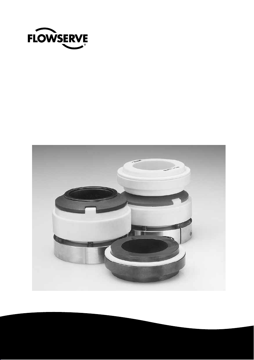
Chemiepac
955, 956, 958, 970, 971, 978
INSTALLATION,
OPERATING,
INSTRUCTIONS
Experience In Motion
Experience In Motion
Page 2

To seal*
Machine manufacturer :
Machine type :
End user :
Plant :
Works standard :
Drawing number : see details based on the order
Article ident. number : see details based on the order
Table of Contents
1.0 Brief description, function
2.0 Information on safety
3.0 General
4.0 Transport, storage
5.0 Preparing for installation
6.0 Installation
7.0 Connecting the fluid supply
8.0 Starting up, operation
9.0 Shutting down, removal
10.0 System check
11.0 Maintenance, replacement parts, aftersales service
IMPORTANT!
CAREFULLY READ AND OBSERVE THESE INSTRUCTIONS AND THE INFORMATION ON
SAFETY BEFORE HANDLING OR STARTUP
FIELD OF OPERATIONS AND PERMITTED USE
The FLOWSERVE CHEMIEPAC is intended exclusively for the sealing of liquids in pumps. All other
instances of use are not permissible. The manufacturer is not liable for any damage incurred through
non-permitted use; the risk is borne by the user alone.
* Should details based on the order not be given, the user shall be responsible for the assignment
according to permitted use.
-2-
Page 3

Installation, Operating and Maintenance Instructions Chemiepac Mechanical Seal
1.0 BRIEF DESCRIPTION, FUNCTION
1.1 Specifications for the operations described herein:
Application limits
Product pressure p (bar) depending on temperature see catalogue
Speed v (m/s) 8
Product temperature t (°C) to 125° C type 970...
to 100° C type 950...
The application limits specified are maximum load values and assist in preselection.
The application limits must be checked for every application.
A warranty in an individual case is possible only when FLOWSERVE knows the exact
application conditions and these have been confirmed in a separate agreement.
1.2 Surface temperature of seal faces:
The temperature class as per EN 13463-1 is based on the expected surface temperature of the faces. The difference between the medium temperature and the surface
temperature of the faces depends on various factors.
The annexed diagram shows how the temperature class can be calculated on the basis
of a temperature difference obtained in practice.
1.3 Brief description
The CHEMIEPAC is a partially assembled mechanical seal system designed to seal
rotating shafts with respect to stationary housings, e.g. a pump shaft with respect to
the housing.
The CHEMIEPAC consists of two units:
The stationary unit is the mating ring (4) with corresponding flat gasket (5). One face
of the mating ring is designed as a seal face, the opposite face is marked “no seal
face”. The mating ring and flat gasket must be connected tightly to the pump housing.
The rotating unit comprises the components 1-3, 6-10, 14 and 15 for the CHEMIEPAC
955, 956 and 958, and 1-3, 6-15 for the CHEMIEPAC 970, 971 and 978. The main
component is the elastic bellows of PTFE that the two-part drive bolts tightly and free
of twisting to the shaft. The face of the bellows is designed as a seal face.
Near the seal face the mechanical properties of the PTFE material are enhanced by
additives. An exchangeable seal ring is available for the CHEMIEPAC 970,971 and 978.
A spring plate (6) is locked along the axis and free of twisting with the bellows and
has built-in springs (3) that are supported in the axial direction against the drive. In
the installed state, the seal faces of the stationary mating ring and the seal face of the
bellows form the seal gap through mutual elastic contact. The medium is sealed from
the atmosphere at the seal gap. The sealing effect is generated by the bellows’ spring
pretension and reinforced by the hydraulic closing force arising from the pressure
exerted by the sealing medium.
-3-
Page 4
1.4 Function
The MS is supplied with liquid from the product.
There must always be liquid at the seal gap to generate a seal film. The seal film also
exists when the shaft is stationary.
When the shaft is rotating the seal faces of the seal and mating rings are separated
from each other by the seal film, and so operate in a virtually non-contacting and nonwearing state.
1.5 Function conditions
The function of the MS is obtained only when the following conditions are fulfilled:
- the seal gap is supplied with clean, solids-free fluid only (solids size < 5µm).
! The product pressure may not exceed the specifications under Item 1.1.
- plane-lapped seal faces.
- perpendicularity between the seal face and the shaft axis.
- unforced freedom of movement of the rotating parts within the specified tolerances.
- prevention of sedimentation on the surfaces of the shaft or shaft sleeve by e.g. crys-
tallization or polymerization.
- prevention of the product from adhering in the area of the seal gap.
- permanent seal film in the seal gap.
- adherence to the specified operating data as per § 1.1 and/or the data sheet.
If these operating requirements are not fulfilled the consumption of product, for
example, is increased or product constituents can escape into the atmosphere. Other
effects can include high component temperatures.
See the directive 94/4/EC and prEN 13463-5; issue 2002; section 4.4.3.
2.0 INFORMATION ON SAFETY
2.1 DANGER: This symbol means that failing to observe this information involves
the risk of personal injury and / or considerable damage to property.
IMPORTANT: This symbol draws your particular attention to important infor-
!
mation that is possibly not clear even to qualified personnel. This information,
however, must be observed to prevent malfunctions that in turn could directly
or indirectly give rise to serious injury and/or property damage.
EXPLOSION PROTECTION: This means that failure to observe these instructions will involve the risk of explosion in potentially explosive environments
which can cause harm to persons and / or considerable damage to property.
2.2 The customer and / or the operator must ensure that all persons assigned to handle,
assemble, and operate the mechanical seal have carefully read these operating instructions before they commence any installation, commissioning, or maintenance work.
Personnel attending to the installation and operation must be fully acquainted with the
layout and function of the MS and its supply system.
-4-
Page 5

Installation, Operating and Maintenance Instructions Chemiepac Mechanical Seal
2.3 Damage may cause leakage in liquid or gaseous form. The hazardous effects
correspond to those of the product, and there may be hazard to persons or
the environment. The operator’s regulations concerning work safety, accident
prevention, and pollution for this plant section must be adhered to without
exception.
2.4 Components coming into contact with the leakage must be corrosion-resistant
!
or corrosion-proof.
2.5 All MSs sent to FLOWSERVE for servicing or repairs must be decontaminated.
!
2.6 When employing elastomers of EP (ethylene-propylene) or butyl rubber, do not
!
use any grease or oil on a mineral basis as a lubricant.
3.0 GENERAL
3.1 All illustrations and details in these operating instructions are subject to technical
alterations that are necessary in improving the MS.
3.2 The copyright on these operating instructions is the property of FLOWSERVE. The-
se operating instructions are intended for the assembly, operating, and supervisory
personnel and contain regulations and drawings of a technical character that may not,
in full or in part, be copied, distributed, used without authorization for competitive
purposes, or given to others.
3.3 We point out that we accept no liability for any instances of damage or malfunctions
incurred through nonadherence to these operating instructions.
4.0 TRANSPORT, STORAGE
4.1 The MS must be transported and stored in the unopened original packaging. The
storage site must be dry and free of dust. Influences through temperature or irradiation
must be avoided.
4.2 Parts or complete MSs that have been dropped or otherwise subjected to heavy im-
pacts during transport must not be installed. An inspection by FLOWSERVE becomes
necessary.
4.3 After a storage period of three years the MS must be inspected for properties as new.
This applies in particular to the secondary seals and seal faces. We recommend an
inspection by FLOWSERVE.
4.4 If the machine is to be preserved with integrated MS the preserving medium
must not impair the functions of the MS by e.g. fouling, hardening, or swelling
the secondary seals.
-5-
Page 6

5.0 PREPARING FOR INSTALLATION
5.1 The MS may be installed when there are no visible signs of damage to the MS.
This applies in particular to the seats, centrings, and the static sealing elements.
Before installing, consult the specifications on the accompanying documents
!
to verify that the correct MS has been installed correctly and is suitable for the
specified application. Do not exceed the design data.
Requisite for all assembly work are the installation drawing and parts list and
!
the tools and aids required for the assembly.
Vibrations must be prevented from transferring to the installed MS during
operation, e.g. through structural measures implemented on the machine.
5.2 The installation chamber for the MS must be checked against the corresponding drawing and table of dimensions. It must be ensured that all dimensions,
surface qualities, and tolerances (e.g. concentricity, run-out, fits) are observed.
The specifications under e.g. ISO 21049 or API 682, DIN 28 161, FLOWSERVE
publication FSD 101, FLOWSERVE publication 127 must be observed.
5.3 Ensure the highest degree of cleanness. Force must not be used to install the CHEMIE-
PAC. Use only suitable tools and aids.
5.4 The seal faces of the MS are important functional sites and may not be damaged.
5.5 All functional and assembly areas for the secondary seals (e.g. O-rings) must be
dimensionally accurate, free of striae and burrs, chamfered, and radiused.
5.6 The locating surfaces of the MS and installation chamber must be undamaged and the
feed pipes and ring channels dry.
5.7 A thin coat of product-compatible grease (e.g. DOW Chemical 111) is to be applied to
the sealing elements (e.g. O-rings). Excess grease is to be avoided.
5.8 Depending on the installation direction, a lubricant, e.g. Molykote M55 or PTFE spray
without solvent, must be applied to the shaft or shaft sleeve.
The areas for the clamp connections must remain free of grease, otherwise the
!
holding force will become inadequate for correct functioning.
Inserting the installation plates.
Place the spring-loaded unit (1–3, 6–[14]15) on a clean surface. Compress the
!
bellows by applying light, uniform pressure to the drive. The installation plates
must not be inserted until just before the actual installation otherwise there will
be a very high downtime leakage for the first 45 minutes. The setting dimension
is obtained when the installation plates are inserted.
-6-
Page 7

Installation, Operating and Maintenance Instructions Chemiepac Mechanical Seal
6.0 INSTALLATION
6.1 Observe the machine manufacturer’s specifications and the following information
when installing the MS in the machine.
The machine to take the MS must be earthed in accordance with the applicable
regulations for electrical installations (e.g. VDE rules) to conduct away any
electrostatic build-up and so prevent spark formation.
6.2 The mating ring with the installed flat gasket must be pressed into the mating ring
mount uniformly by hand or under a press. The seal face is protected with a lapped
plate or the seal ring. Use oil or grease as a lubricant (see Item 5.7).
Tighten the cover uniformly and flatly.
Under no circumstances may O-rings of EP rubber come into contact with
!
mineral oil or grease (see item 5.7).
6.3 Push the spring-loaded unit (items 1 - 3, 6-[14] 15 ) on the shaft or shaft sleeve.
Displace the drive (item 9) until the setting dimension is obtained, and bolt firmly to
the shaft or shaft sleeve with (item 8).
Max. tightening torques (Nm) for item 8:
Thread (mm) For material: 1.4571 / 2.4610
M5 2.3
M6 5
M8 9
M10 17
M12 51
When the shaft is of e.g. PTFE, PP, or elastomers the drive (9) must be secured in addition along the axis (packing gland).
!
After tightening the drive, the installation plates must always be removed.
!
Components provided by the customer for installing the MS, e.g. the pump
cover or fastening bolts, must exhibit adequate properties and dimensions. It
must not be possible to overstress these components, e.g. the max permitted
tightening torque must not be exceeded.
6.4 To reduce friction forces during installation the shaft or shaft sleeve is lubricated
!
with a thin coat of oil or grease in the area of the dynamic sealing element (see
Item 5.7).
6.5 Conduct a static pressure test. Do not exceed the max pressures under item 1.1.
-7-
Page 8

6.6 Should there be gas or air pockets in the sealing chamber, these can accumulate with
the rotation at the outer diameter of the seal gap at machine start-up. As a consequence the machine runs dry at the seal gap for an undefined period and damage may
be caused to the seal faces.
7.0 CONNECTING THE FLUID SUPPLY
7.1 The MS is operated with a fluid supply system in accordance with the specifications
from the machine manufacturer. To carry off the heat generated by friction and to prevent deposits in the area of the seal face, adequate liquid circulation must be ensured,
e.g. feed from the discharge branch of the pump. The inlet of the circulation pipe (min.
1/4“) in the seal cover must be in the area of the seal gap. The seal gap is supplied
with clean, solids-free fluid only.
Escaping leakage must not form an explosive mixture.
Forced ventilation must be ensured in the sealing chamber when the circulati-
on line is connected. Should there be gas or air pockets in the sealing chamber, these can accumulate with the rotation at the outer diameter of the seal
gap at machine start-up. As a consequence the machine runs dry at the seal
gap for an undefined period and damage may be caused to the seal faces.
Monitoring the liquid circulation is a recommended measure for ensuring that
the MS operates properly.
Suitable measures must be implemented to prevent errors in the operation of
shut-off and throttling devices installed in the fluid supply.
8.0 STARTING UP, OPERATION
The MS is ready for operation after it has been installed, the fluid supply connected,
and the sealing chamber carefully vented.
The Chemiepac 955-958 must not be operated with normal water. The addition
!
of a wetting agent is recommended. Please wait for at least twenty minutes
before starting up the seal.
It must be ensured that the machine is protected against penetration by dust
and / or that dust deposits are removed at regular intervals so that they cannot
exceed a thickness of 5 mm on the surfaces of the faces.
It must be ensured, e.g. in the form of a level monitor, that the sealing chamber is completely vented and filled with liquid in all operating states if it is to
minimise the heat generated by friction and therefore the surface temperature
of the seal elements.
If the application limits for operations in accordance with these instructions
cannot be observed, the temperature of the supply fluid and / or the installed
-8-
Page 9

Installation, Operating and Maintenance Instructions Chemiepac Mechanical Seal
components must be monitored at all times by a device that shuts down the
machine once a critical temperature is reached. This device can consist of
resistance thermometers or thermoelements.
8.1 The installed MS is bi-directional.
8.2 The sealing chamber must be vented carefully before startup.
8.3 During the static pressure test on the pump the test pressure must not exceed the
specifications (see § 1.1).
8.4 To carry off the heat generated by friction and to prevent deposits in the area of the
seal faces, adequate circulation must be ensured for the supply fluid, e.g. forced
circulation.
At all operating temperatures the product must not come within 20 K of its
evaporating point. Should this not be the case during certain operating situations (e.g. shutdown, start-up) forced circulation or adequate cooling must be
generated to promote heat removal.
Escaping leakage must not form an explosive mixture.
8.5 Pressure should be applied to the product in a step-by-step process, and not abruptly.
Exceeding the max pressures given under item 1.1 will cause damage to the
!
MS.
8.6 Operation, malfunctions
SYMPTOM CAUSE
Large loss of product - shaft eccentric.
- pipe connection leaks.
- damage to the MS
(product exits into atmosphere)
Fluid supply temperature
too high
8.7 The pump shaft may be stopped at any time.
9.0 SHUTTING DOWN, REMOVAL
9.1 The machine may be shut down at any time under normal circumstances.
9.2 Before the MS is removed the machine must be shut down and depressurised.
9.3 The shaft may be shut down under pressure.
9.4 Remove the MS by following the instructions for installation in reverse order.
Removing the pressure transmitter may release medium! All information and
- product pressure too high (higher friction)
- lack of supply fluid
-9-
Page 10

regulations regarding safety measures and protective clothing with respect to
this plant section must be observed and strictly adhered to. The operator must
ensure the proper disposal of the media collected when the machine is vented
or drained.
9.5 Carefully replace the removed MS in the original packaging (e. g. wooden crate) and
store or send this to FLOWSERVE for inspection.
10.0 SYSTEM CHECK
Routine maintenance of the MS extends to the monitoring of the set values for pressu-
re, temperature, and leakage quantity.
Routine maintenance must be conducted at suitable intervals to prevent soiling
in or on shut-off and throttle devices installed in the fluid supply.
10.1 Removing the MS for an inspection becomes necessary when:
- the specified leakage values are exceeded and, after enquiries at FLOWSERVE, no
other written agreement ensues.
- after an installation period of more than three years.
- an inspection of the pump is due, and a similarly long operating period is expected
thereafter.
11.0 MAINTENANCE, REPLACEMENT PARTS, AFTERSALES SERVICE
11.1 Repairs must be conducted by FLOWSERVE within the guarantee period. In special
cases (emergencies) competent personnel may replace individual parts in situ after
consultation with FLOWSERVE.
11.2 Replacement parts are to be ordered with the ID numbers given in the annexed
parts list.
!
11.3 A warranty is given only for the original replacement parts delivered by
FLOWSERVE. All parts of the MS meet with high-precision dimensional
!
tolerances and are matched to one another. Only a part replacement as
given in the FLOWSERVE quality assurance documentation ensures smooth
operation.
11.4 We expressly point out that original replacement parts and accessories not
delivered by FLOWSERVE are not tested or released by FLOWSERVE. Under
!
certain circumstances therefore, usind and / or installing such products may
impair the properties given in the MS design and hence undermine the active
and / or passive safety. All incidents of damage incurred through the use of
nonoriginal replacement parts or appurtenances render all liabilities and warranties on the part of FLOWSERVE void.
Please note that special manufacturing and delivery specifications exist for all parts
-10-
Page 11

Installation, Operating and Maintenance Instructions Chemiepac Mechanical Seal
of our products manufactured or procured by ourselves, and the replacement parts
are always offered in accordance with the latest technology and with the most current
regulations and laws.
The MS cannot function during all assembly and maintenance work.
!
-11-
Page 12

FIS177eng Rev 07/05 Printed in Europe
flowserve.com
To find your local Flowserve representative
and find out more about Flowserve Corporation, visit
www.owserve.com
Flowserve Corporation has established industry leadership in the design and manufacture of its products. When properly selected, this Flowserve product is designed to perform its intended function safely during its useful life. However, the purchaser or user of Flowserve products should be aware that Flowserve products might be used in numerous
applications under a wide variety of industrial service conditions. Although Flowserve can provide general guidelines,
it cannot provide specic data and warnings for all possible applications. The purchaser/user must therefore assume
the ultimate responsibility for the proper sizing and selection, installation, operation, and maintenance of Flowserve
products. The purchaser/user should read and understand the Installation Instructions included with the product, and
train its employees and contractors in the safe use of Flowserve products in connection with the specic application.
While the information and specications contained in this literature are believed to be accurate, they are supplied for
informative purposes only and should not be considered certied or as a guarantee of satisfactory results by reliance
thereon. Nothing contained herein is to be construed as a warranty or guarantee, express or implied, regarding any
matter with respect to this product. Because Flowserve is continually improving and upgrading its product design,
the specications, dimensions and information contained herein are subject to change without notice. Should any
question arise concerning these provisions, the purchaser/user should contact Flowserve Corporation at any one of
its worldwide operations or ofces.
© Copyright 2005 Flowserve Corporation
USA and Canada
Kalamazoo, Michigan USA
Telephone: +1 269 381 2650
Telefax: +1 269 382 8726
Europe, Middle East, Africa
Essen, Germany
Telephone: +49 201-31 93 70
Telefax: +49 201-2200-561
Asia Pacific
Singapore
Telephone: +65 6544 6800
Telefax: +65 6214 0541
Latin America
Mexico City
Telephone: +52 55 5567 7170
Telefax: +52 55 5567 4224
 Loading...