

Fisher & Paykel WH8560J1, WH8560P1, WH8060P1, WH7560J1, WH7560P1 Service Manual

479646
Service Manual
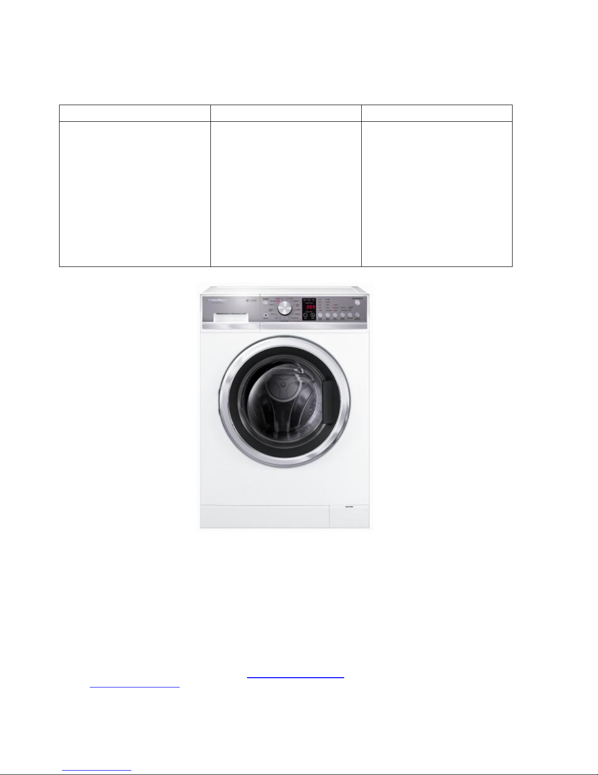
Front Load Washer
Models:
WH8560P1
WH8560J1
WH8060P1
WH7560P1
WH7560J1
479646 - OCTOBER 2014
Fisher & Paykel Appliances Ltd
78 Springs Road
East Tamaki
Auckland 2013
PO Box 58-546, Botany
Auckland 2163
New Zealand
Phone: 09 273 0600
Fax: 09 273 0656
Email: customer.care@fp.co.nz
Fisher & Paykel Customer Services Pty Ltd
PO Box 798, Cleveland, QLD 4163
A.C.N. 003 3335 171
19 Enterprise Street
Cleveland, QLD 4163
Australia
Telephone: (07) 3826 9100
Facsimile: (07) 3826 9164
E-mail: customer.care@fp.com.au
Fisher & Paykel Singapore Pte Ltd
150 Ubi Avenue 4
#03-01A
Ubi Biz-hub
Singapore 408825
Telephone: +65 65470100
Facsimile: +65 65470123
COPYRIGHT FISHER & PAYKEL LTD 2014 - ALL RIGHTS RESERVED
2
The specifications and servicing procedures outlined in this manual are subject to change without notice.
The latest version is indicated by the reprint date and replaces any earlier editions
PRODUCT
Brand
Product Code
Model
Fisher & Paykel
92141
92142
92136
92137
93161
95141
95142
95108
95109
WH8560P1 FP AA
WH8560J1 FP AA
WH7560P1 FP AA
WH7560J1 FP AA
WH8060P1 FP AA
WH8560P1 FP SG
WH8560J1 FP SG
WH7560P1 FP SG
WH7560J1 FP SG

479646
3
CONTENTS
1 HEALTH & SAFETY ................................................................................................................................ 5
2 SPECIFICATIONS ................................................................................................................................... 6
2.1 Product Dimensions ............................................................................................................................ 6
2.2 Product weight .................................................................................................................................... 6
2.3 Water Rating ....................................................................................................................................... 6
2.4 Energy Rating ..................................................................................................................................... 7
2.5 Noise Rating ........................................................................................................................................ 7
2.6 Heating Element .................................................................................................................................. 7
2.7 Temperature Sensor ........................................................................................................................... 7
2.8 Detergent/Softener Dispenser ............................................................................................................ 7
2.9 Wash Motor ......................................................................................................................................... 7
2.10 Water Inlet Valves ............................................................................................................................... 8
2.11 Pressure Sensor ................................................................................................................................. 8
2.12 Drain Pump ......................................................................................................................................... 8
2.13 Door Lock ............................................................................................................................................ 8
2.14 Flood Protection .................................................................................................................................. 8
2.15 Motor EMI Filter ................................................................................................................................... 8
2.16 EMI Filter Capacitor ............................................................................................................................ 8
2.17 Product Finish ..................................................................................................................................... 9
2.18 Drain Filter ........................................................................................................................................... 9
3 SERIAL LABEL ..................................................................................................................................... 10
4 INSTALLATION ..................................................................................................................................... 11
4.1 Water Connection ............................................................................................................................. 12
4.2 Levelling ............................................................................................................................................ 12
4.3 Drain Hose ........................................................................................................................................ 12
5 OPERATION .......................................................................................................................................... 13
5.1 Control Panel Layout ......................................................................................................................... 13
5.2 Power off Memory Function .............................................................................................................. 14
5.3 Operating Modes ............................................................................................................................... 14
5.3.1 Drain Pump ................................................................................................................................ 14
5.3.2 Filling With Water ...................................................................................................................... 14
5.3.4 Add a Garment (P models only) ................................................................................................ 14
5.3.5 End of Cycle .............................................................................................................................. 14
5.4 Wash Progress Display ..................................................................................................................... 14
6 WASH PROGRAMS .............................................................................................................................. 15
6.1 Wash Program Chart ........................................................................................................................ 15
7 SERVICING PROCEDURES ................................................................................................................. 17
7.1 Component Location ......................................................................................................................... 17
7.2 Dis-assembly Procedure ................................................................................................................... 18
7.2.1 Removal of Top Panel ............................................................................................................... 18
7.2.2 Removal of Rear Cover ............................................................................................................. 18
7.2.3 Removal of Kick Panel .............................................................................................................. 19
7.2.4 Removal of Cabinet Bellows Clamp .......................................................................................... 19
7.2.5 Removal of Control Panel ......................................................................................................... 19
7.2.6 Replacing the Display Module ................................................................................................... 20
7.2.7 Removal of the front Panel ........................................................................................................ 20
7.2.8 Removal of the Drum Assembly ................................................................................................ 21
7.2.9 Replacing Drum Vane ............................................................................................................... 22
7.2.10 Removal of the Door Lock ......................................................................................................... 22
7.2.11 Removal of the Door ................................................................................................................. 23
7.2.12 Pump Blockages........................................................................................................................ 23
7.2.13 Removal of the Drain Pump ...................................................................................................... 23
7.2.14 Removal of Water Valves .......................................................................................................... 24
7.2.15 Removal of the Heater .............................................................................................................. 24
7.2.16 Removal of the Rotor ................................................................................................................ 25
7.2.17 Removal of the Stator ................................................................................................................ 25
7.2.18 Removal of the Motor Controller ............................................................................................... 26

479646
4
8 WIRING DIAGRAM & COMPONENT RESISTANCES .........................................................................27
9 CONNECTOR LAYOUT .........................................................................................................................28
10 MODEL/SIZE SETTING .........................................................................................................................29
11 DIAGNOSTIC MODE .............................................................................................................................30
11.1 Self Test ........................................................................................................................................... 30
11.2 Water Valve Tests ............................................................................................................................ 31
11.3 Drum Rotation Test .......................................................................................................................... 31
11.4 Door Lock Test ................................................................................................................................. 31
11.5 Heater Test ....................................................................................................................................... 31
12 SHOW ROOM MODE ............................................................................................................................32
13 FAULT CODES ......................................................................................................................................33
13.1 Fault Code Flow Charts .................................................................................................................... 34
13.1.1 Door Open .................................................................................................................................34
13.1.2 No Tap .......................................................................................................................................35
13.1.3 Err 7:00 ......................................................................................................................................36
13.1.4 Err 7:01 ......................................................................................................................................37
13.1.5 Err 7:02 ......................................................................................................................................38
13.1.6 Err 7:03 ......................................................................................................................................39
13.1.7 Err 7:04 ......................................................................................................................................40
13.1.8 Err 7:06 ......................................................................................................................................41
13.1.9 Err 7:07 ......................................................................................................................................42
13.1.10 Err 7:08 ......................................................................................................................................43
13.1.11 Err 7:09 ......................................................................................................................................44
13.1.12 Err 10 .........................................................................................................................................45
13.1.13 Err 12 .........................................................................................................................................46
13.1.14 Err 37 .........................................................................................................................................47
13.1.15 Err 74 .........................................................................................................................................48
13.1.16 Err 75 .........................................................................................................................................49
13.1.17 Err 105 .......................................................................................................................................50
13.1.18 Err 235 .......................................................................................................................................51
13.2 Trouble Shooting Flow Charts .......................................................................................................... 52
13.2.1 Unit Will Not Power Up ..............................................................................................................52
13.2.2 No Water ....................................................................................................................................53
13.2.3 Not Draining ...............................................................................................................................54
13.2.4 Abnormal Noise and Vibration ...................................................................................................55
13.2.5 Leaking Water ............................................................................................................................56
14 DIAGNOSTICS LEVELS ........................................................................................................................57
15 SOLVING OPERATING PROBLEMS ...................................................................................................60
15.1 Wash Cycle Time Variations ............................................................................................................ 60
15.2 Detergent/Fabric Softener Remaining in the Dispenser .................................................................. 60
15.3 Washing Comes out Very Wet at Cycle End .................................................................................... 60
16 SOLVING WASH PROBLEMS ..............................................................................................................61
16.1 Creasing ........................................................................................................................................... 61
16.2 Poor Soil Removal ............................................................................................................................ 61
16.3 Dye Transfer ..................................................................................................................................... 61
16.4 Black or Grey Marks on Washing ..................................................................................................... 61
16.5 Tangling ............................................................................................................................................ 61
479646
5
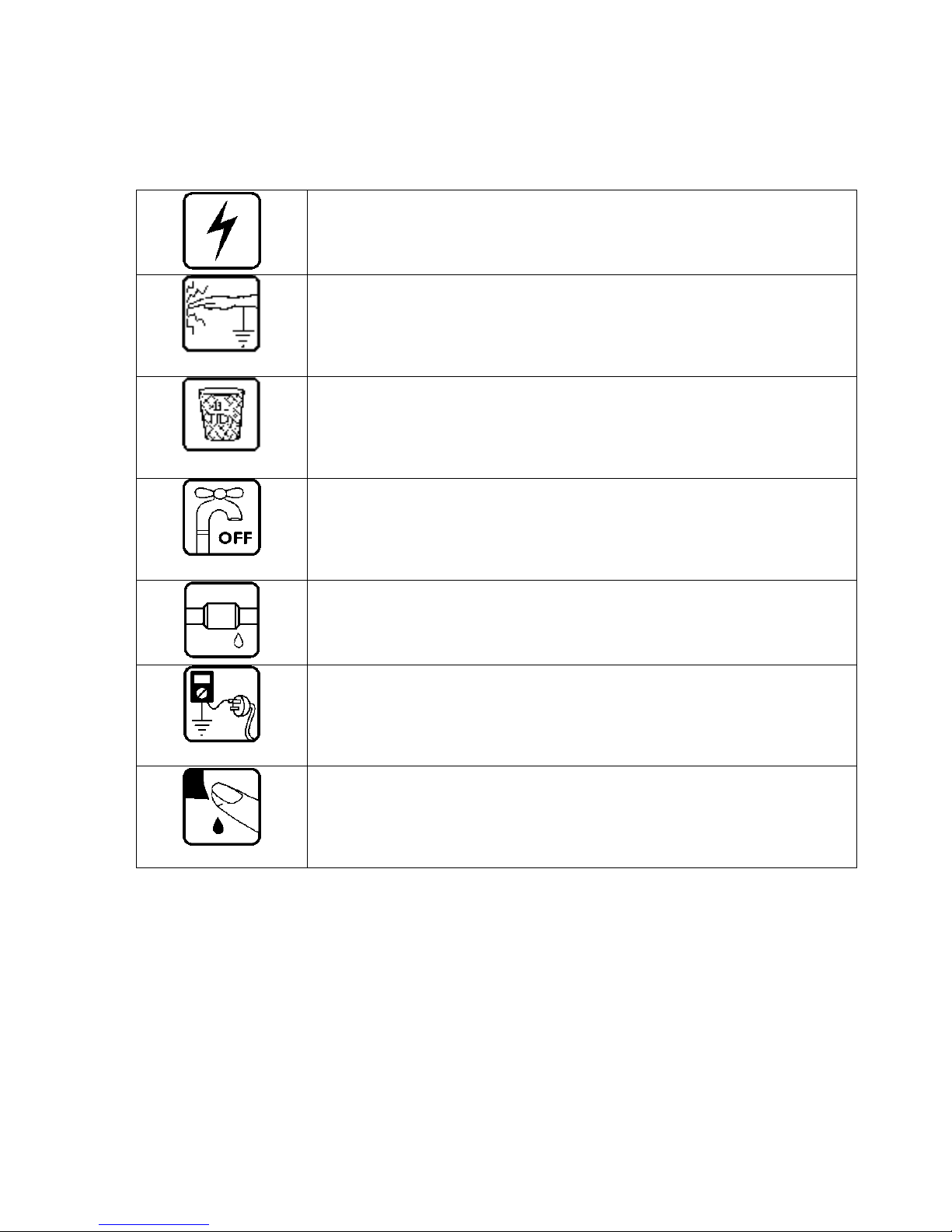
1 HEALTH & SAFETY
When servicing the washer, health & safety issues must be considered at all times. Specific safety issues are
listed below with the appropriate icon.
Electrical Safety
Ensure the mains power has been disconnected before servicing the washer.
If the mains supply is required to be on to service the washer, make sure it is
turned off when removing any electrical component or connection to avoid electric
shock.
Electrostatic Discharge
An anti-static strap is to be used as electrical static discharge (ESD) protection
when servicing electronic components.
Good Working practices
Ensure the work area is in a tidy and orderly condition at all times so as not to
cause a hazard while service work is being completed. Always clean and tidy the
washer and work area after service is completed.
Isolate Water Supply
Turn off the water connection tap before servicing
Water Leak Check
Check for water leaks as part of the testing after the service has been completed.
Insulation test
Megger test to check insulation
Warning: short together the phase and neutral pins on the plug so not to damage
any electronic circuitry.
Sharp Metal Edges
When working around cut sheet metal edges, use appropriate gloves or protection
to eliminate the change of receiving a laceration.
479646
6
2 SPECIFICATIONS
2.1 Product Dimensions
Model
Width
Depth
Height
WH8560
600mm
650mm
850mm
WH8060
600mm
650mm
850mm
WH7560
600mm
590mm
850mm
2.2 Product weight
Model
Kgs
WH8560
69
WH8060
69
WH7560
69
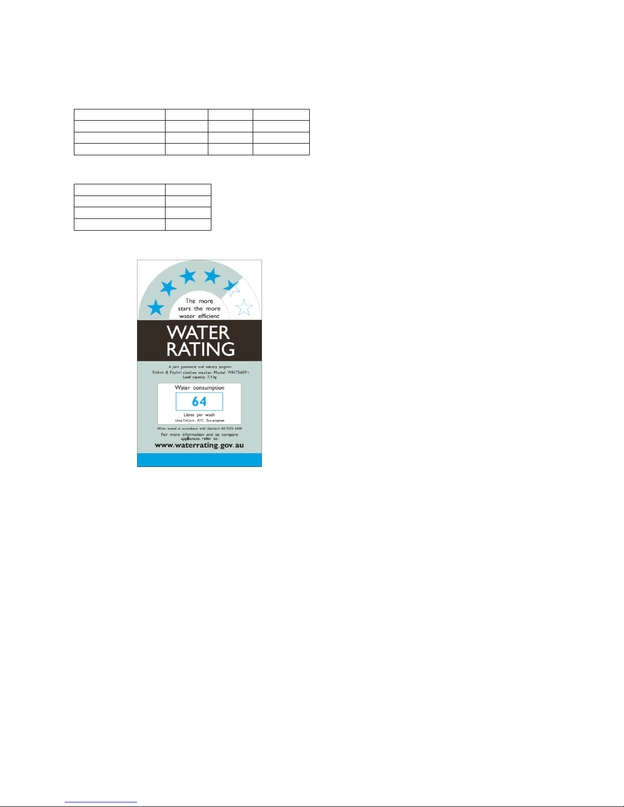
2.3 Water Rating
4.5 Star Water rating using the Cotton 40OC cycle.
479646
7
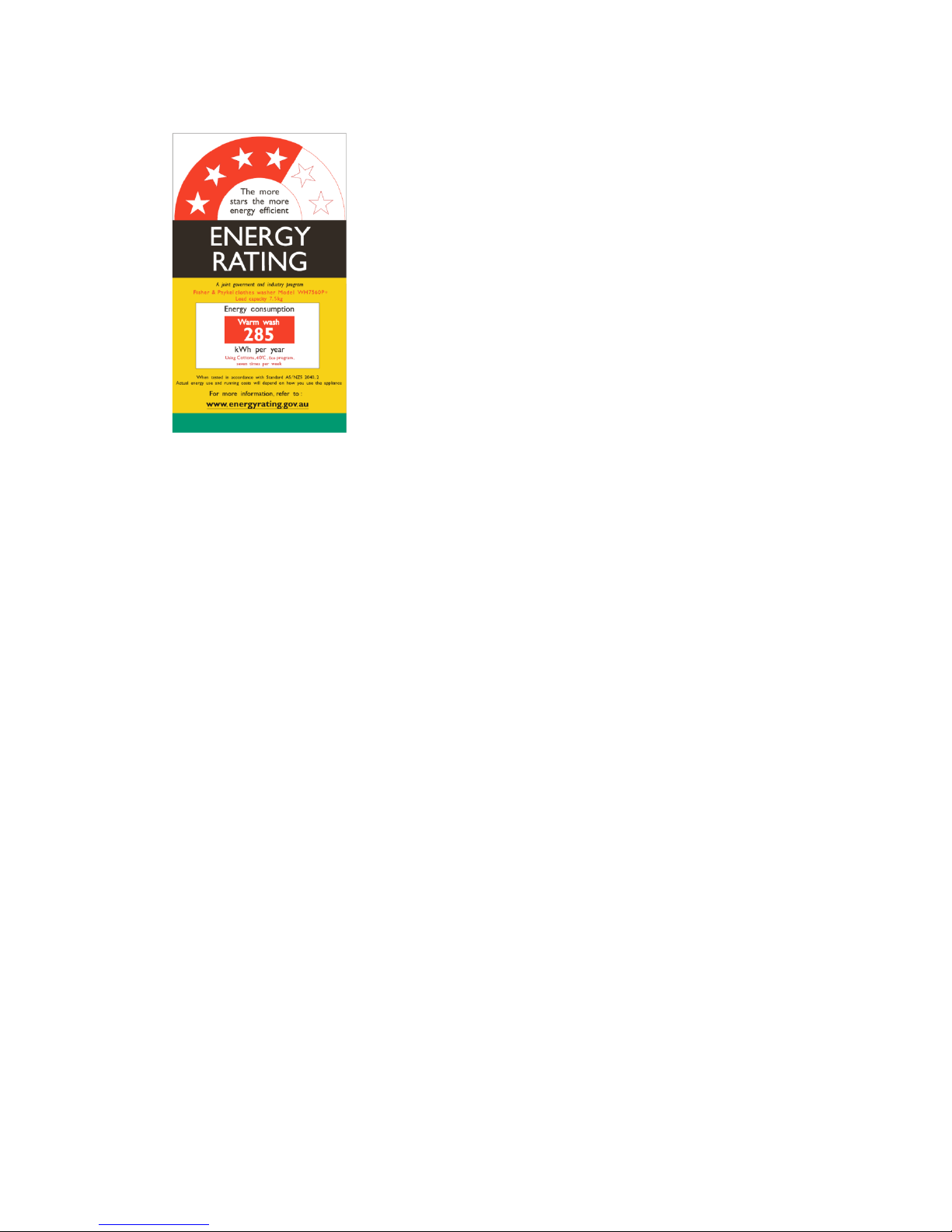
2.4 Energy Rating
220V - 240V AC, 50Hz, 2000W, 10Amp maximum
4 Star rating
2.5 Noise Rating
72 dB
2.6 Heating Element
1800 Watts.
Resistance 30Ω.
Overheat protection thermal link 167OC.
2.7 Temperature Sensor
NTC type: Reduces in resistance as temperature rises.
Resistance 13K Ω @ 25 oC.
2.8 Detergent/Softener Dispenser
Compartments: There are three: Prewash, Main Wash and Softener
Pre Wash and Main wash are for powder detergent only DO NOT USE LIQUIDS.
2.9 Wash Motor
Electronically commutated 27 pole direct drive 3 phase brushless DC motor.
Motor Resistance @20oC (68oF): 14.5Ω +/- 10% (28Ω +/- 1.95Ω phase to phase).

479646
8
2.10 Water Inlet Valves
Cold Valve dual type.
Hot valve single type.
220V – 240V AC 50Hz.
Resistance 4 KΩ +/- 5%.
Cold maximum inlet temperature 35OC.
Hot maximum inlet temperature 65OC.
2.11 Pressure Sensor
The machine is fitted with a pressure sensor, which controls the fill to any water level. The pressure sensor
is a stand alone component which is replaceable and is connected to the tub air chamber via the pressure
tube.
2.12 Drain Pump
220V – 240V AC 50Hz.
Total power 30W.
Resistance 212 Ω.
Pump out rate 15litres/min.
Overheat protection thermal link 105OC.
2.13 Door Lock
Type Solenoid Activated.
With mechanical release.
Resistance Terminal 2 & 3 190Ω 10%.
Nominal Voltage Terminal 2&3 230V.
2.14 Flood Protection
Pressure sensor activated.
The drain pump will run when pressure switch is activated and fault code 12 will be displayed.
2.15 Motor EMI Filter
Inductor – 7.8mH
2.16 EMI Filter Capacitor
X Capacitor 0.47uF
Y Capacitor 470nF
L Inductor > 4mH
479646
9
2.17 Product Finish
Cabinet - sheet metal powder coated.
Inner drum - stainless steel.
Outer tub – plastic.
Outer door frame – plastic.
Inner door – glass.
Front panel – plastic.
Kick panel – plastic.
Detergent dispenser – plastic.
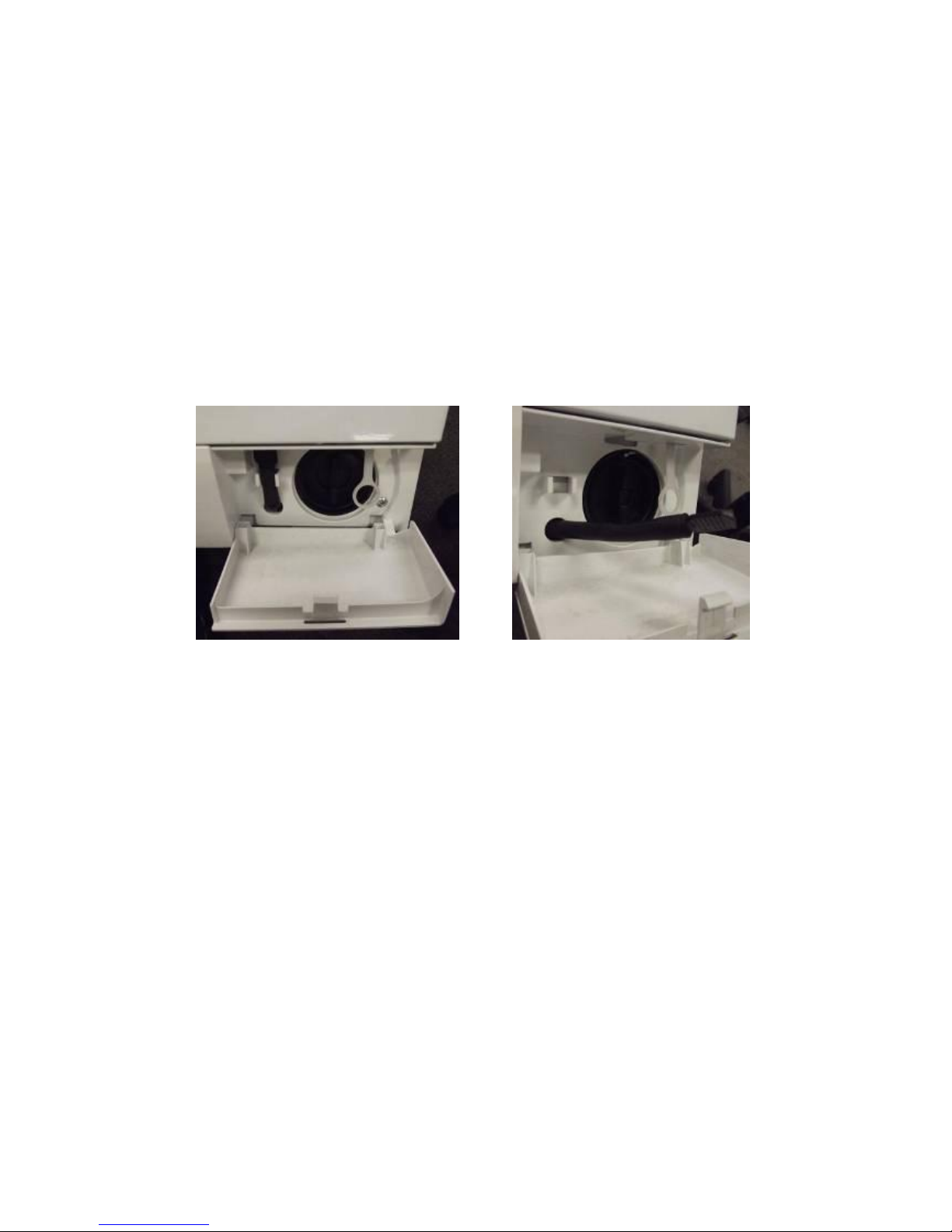
2.18 Drain Filter
Recommended to be cleaned once a month.
Open the filter compartment cover in the lower right hand corner and unhook the pump outlet hose
pulling it out (about 150mm), remove the plug and drain residual water into a shallow dish.
Replace the plug into the hose and refit hose back into housing.
Remove filter by turning counter-clockwise.
Flush clean with running water.
Refit it the reverse procedure

479646
10
3 SERIAL LABEL
The serial label is located on the front panel top centre of the door porthole.
.
The last 9 digits of serial number indicate where manufactured, date of manufacture and sequential number.
CR D 2 G 0001
CR= Manufacture code 0959= Product number
D= Year 2013 G= 16th Day
2= 2nd Month
Year
2013
2014
2015
2016
2017 D E F G
H
Month
Jan
Feb
Mar
Apr
May
Jun
Jul
Aug
Sep
Oct
Nov
Dec
1 2 3 4 5 6 7 8 9 A B
C
Day
1 2 3 4 5 6 7 8 9
10
11
12
13
14
15
1 2 3 4 5 6 7 8 9 A B C D E F
16
17
18
19
20
21
22
23
24
25
26
27
28
29
30
31 G H J K L M N P Q R S T U V W X
479646
11
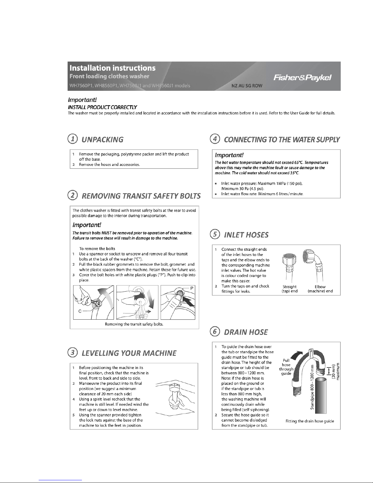
4 INSTALLATION
479646
12
4.1 Water Connection
Hot & cold inlet valves.
30 kPa (4.3PSI) Minimum water pressure.
1000 kPa (145PSI) Maximum water pressure.
4.2 Levelling
50mm Adjustment height
Level within – 2 degrees side to side & front to back.
4.3 Drain Hose
1.2M Length of standard hose
2.5M Max length if extended
1200mm Max pump from floor
800mm Minimum
479646
13
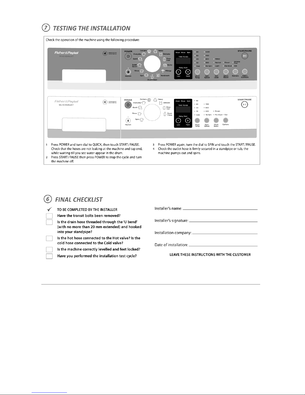
5 OPERATION
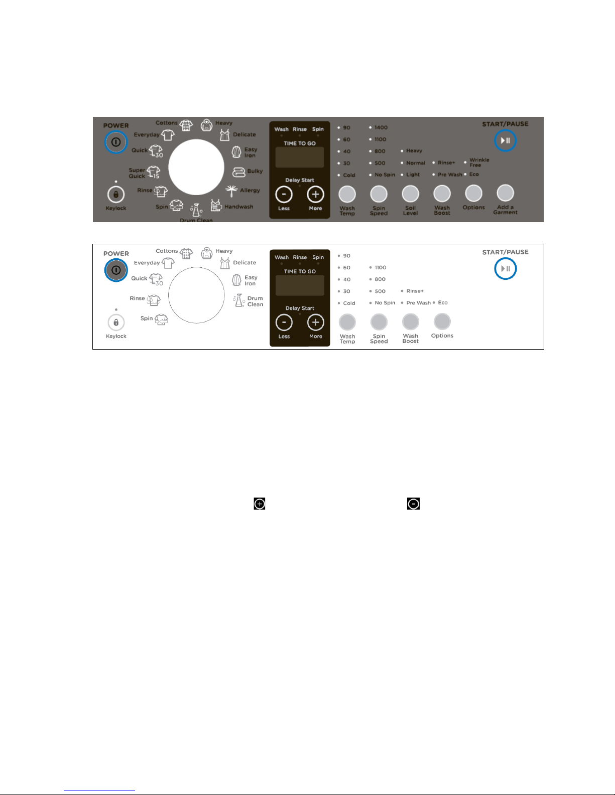
5.1 Control Panel Layout
WH8560J1/WH75J1 (QuickSmart)
Power Button
Used to switch washer on and off.
Key Lock
Activated and deactivated by pressing the KEY LOCK button for 2 seconds. Once activated, the light above
the button is illuminated.
Program Knob
Rotary action with up to 13 programs dependent on model.
Delay Start
Enables delay of the the start of the wash cycle from between 5 minutes and 12 hours. To program the
delay start time simply use the MORE button to increase and the LESS button to decrease the time or
to turn the delay start off.
Display Screen
Displays the remaining wash time, user warning, any error messages and wash progress.
Wash Temperature
Used to select wash temperatures which are adjustable from cold to 90 oC but is dependent on wash cycle
selected.
Spin Speed
Used to select desired spin speed between no spin and 1400 rpm but is dependent on model and the wash
cycle selected.
Soil Level (P models only)
Used for adjusting the wash to suit the amount of soil in the load. Heavy for dirty clothes, Light for lightly
soiled clothes. These adjust the wash time accordingly.
Wash Boost
Allows the selection of an extra rinse (Rinse +) to the program and/or a Pre Wash for extra dirty loads.
WH85/7560P1 (WashSmart) WH8060P1

479646
14
Options
Press this button to select the ECO and Wrinkle free functions.
Wrinkle free (P models only) is for loads that are not going to be removed after the completion of the wash
cycle and will tumble the clothes every 15 minutes for up to 12 hours.
The ECO function saves energy and water. This function reduces the wash temperature slightly and
increase the wash time by approximately 10 minutes.
Add a Garment (P models only)
Used to add or remove items during the wash stage of the cycle under certain conditions. It will only operate
during the wash cycle and if the wash temperature is less than 60OC.
Start/ Pause
Press this button to start the selected wash cycle. Operation can be paused at any time by pressing the
button. The display will begin to blink and the operation will stop. To continue, press the button again.
5.2 Power off Memory Function
The machines have a built in memory function. If the power goes off, the washing machine will remember
the current settings and place in the wash cycle. It will automatically return to the same place in the cycle
and continue when the power is restored.
5.3 Operating Modes
5.3.1 Drain Pump
The filter of the drain pump requires cleaning approximately once a month. The pump will automatically
activate if the machine over fills.
5.3.2 Filling With Water
The machine fills with a combination of cold & hot water for the main wash e.g. Cotton 60, with the rinse
being of cold water.
5.3.3 Washing and Heating
When the wash requires a wash temperature that is greater than the mixed inlet temperature, the machine
heats the water with an on board element. The temperature is subject to the program selection and is
monitored by the temperature sensor.
5.3.4 Add a Garment (P models only)
This function is only available during a wash cycle with a selected wash temperature below 60 degrees.
When the ADD A GARMENT button is activated, the machine will pause and the start/pause LED will flash.
The pump will turn on and pump out some of the wash water if the level is above the door seal. To continue
the wash, press the start/pause button.
5.3.5 End of Cycle
At the end of cycle the machine stops automatically with the screen displaying the word END.
5.4 Wash Progress Display
The display has LED indicators that illuminate as the machine progresses through each of the steps of the
cycle: Wash, Rinse and Spin.

479646
15
6 WASH PROGRAMS
6.1 Wash Program Chart
WASHSMART
Cycle
Designed for
Max.
Load
size
(Kg)*
Default Setting
Default
Cycle
Time
Cottons**
Normally Soiled
everyday cotton loads
7.5 , 8.0
or 8.5
1400 rpm
40OC
2:17
Everyday
Normally or lightly
soiled everyday
items
7.5, 8.0
or 8.5
1400 rpm
40OC
1:00
Heavy
Heavy soiled durable
garments
7.5, 8.0
or 8.5
1400 rpm
60OC
2:10
Delicate
Delicate lightly soiled
items
4
500 rpm
40OC
0:45
Easy Iron
Minimising creasing
4
800 rpm
40OC
1:04
Bulky
Washing bulky items
4
800 rpm
40OC
1:50
Allergy
Asthma sufferers &
people with skin
sensitivities
7.5, 8.0
or 8.5
1400 rpm
60OC
2:30
Handwash
Very delicate lightly
soiled garments
2
500 rpm
30OC
0:45
Quick
Lightly soiled
garments
4
800 rpm
40OC
0:30
Super
Quick
Freshening up small
musty or lightly
soiled items
2
800 rpm
40OC
0:15
Rinse
Items that require
rinsing only
7.5, 8.0
or 8.5
1400 rpm
Cold
0:25
Spin
Spinning of wet
items
7.5, 8.0
or 8.5
1400 rpm
N/A
0:12
Basket
Clean
Maintaining the
cleanliness of your
washer
N/A
1400 rpm
90OC
0:59
* Depends on your model of washer (7.5kg or 8.5 kg capacity).
** Cottons, 40
o
C, 1400rpm, normal soil level and Eco option selected is the recommended water and
energy saving cycle for normally soiled, everyday washing.
479646
16
QUICKWASH
Cycle
Designed for
Max.
Load
size
(Kg)*
Default Setting
Default
Cycle
Time
Cottons**
Normally Soiled
everyday cotton loads
7.5 or
8.5
1100 rpm
40OC
2:17
Everyday
Normally or lightly
soiled everyday
items
7.5 or
8.5
1100 rpm
40OC
1:00
Heavy
Heavy soiled durable
garments
7.5 or
8.5
1100 rpm
60OC
2:10
Delicate
Delicate lightly soiled
items
4
500 rpm
40OC
0:45
Easy Iron
Minimising creasing
4
800 rpm
40OC
1:04
Quick
Lightly soiled
garments
4
800 rpm
40OC
0:30
Rinse
Items that require
rinsing only
7.5 or
8.5
1100 rpm
Cold
0:25
Spin
Spinning of wet
items
7.5 or
8.5
1100 rpm
N/A
0:12
Basket
Clean
Maintaining the
cleanliness of your
washer
N/A
1100 rpm
90OC
0:59
* Depends on your model of washer (7.5kg or 8.5 kg capacity).
** Cottons, 40 oC, 1100rpm, normal soil level and Eco option selected this is the recommended water and
energy saving cycle for normally soiled, everyday washing.
479646
17
7 SERVICING PROCEDURES
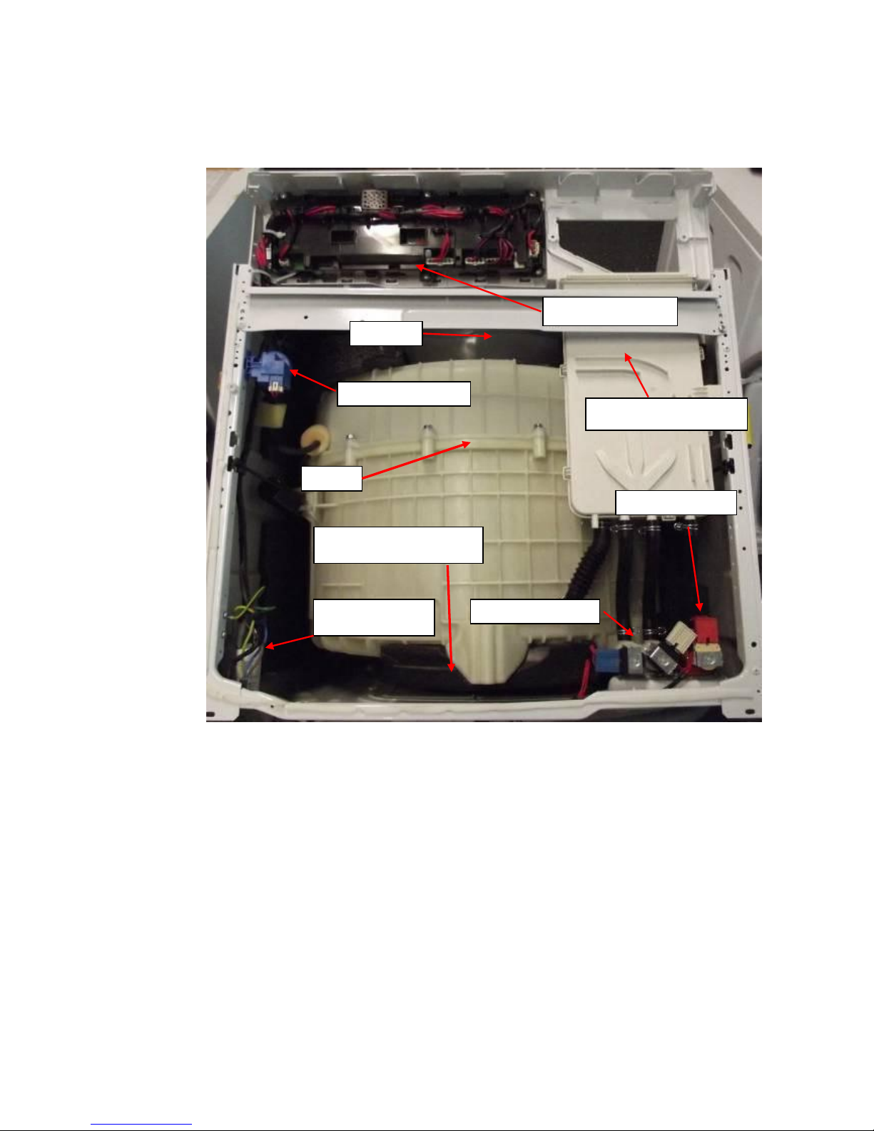
7.1 Component Location
Pressure Sensor
Detergent Dispenser
Cold inlet valves
Hot inlet valve
RFI Capacitor
Tub
Upper Counter weight
Bellows
Display Module
479646
18
7.2 Dis-assembly Procedure
7.2.1 Removal of Top Panel
1. Remove the 2 self-tapping screws securing
the top panel to the rear of the cabinet. Slide
the top panel toward the rear to clear the
side locators and then upwards to take off.
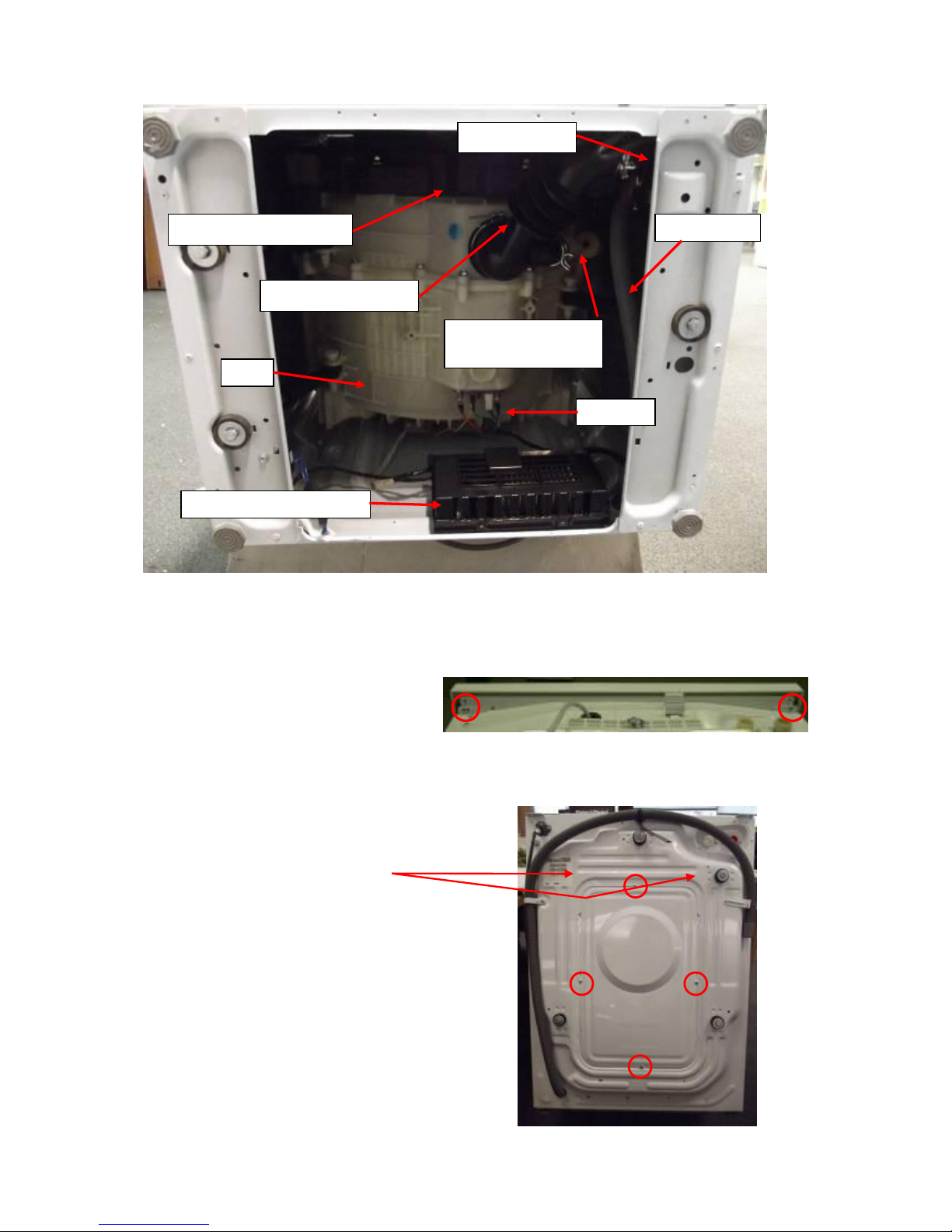
7.2.2 Removal of Rear Cover
1. Remove 4 self-tapping screws holding the rear
cover to the rear of the cabinet.
2. To remove the rear cover, slide it down and out
from the locating slots.
Reassemble in the reverse order.
Drain Pump
Tub to Pump Hose
Air chamber for
pressure sensor
Motor controller module
Heater
Front counter weights
Drain Hose
Tub
479646
19
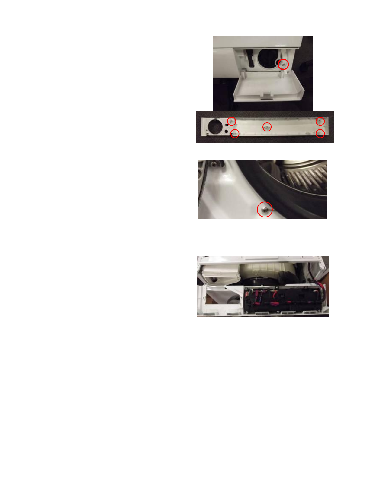
7.2.3 Removal of Kick Panel
1. To remove the kick panel, open the pump cover
and drain the pump of any water (refer to
Section 2.18).
2. Remove the screw.
3. Carefully unclip the kick plate from its locking
clips.
NB. If too tight to free, then remove the base panel
and release the 5 clips from the inside of the front
panel.
Reassemble in the reverse order
7.2.4 Removal of Cabinet Bellows Clamp
1. Undo the screw holding the clamp in position.
2. Unhook the wire clamp to separate and remove.
3. Remove bellows from cabinet.
Reassemble in the reverse order
7.2.5 Removal of Control Panel
1. Follow the procedure for removal of top panel
(refer to Section 7.2.1).
2. Remove dispenser drawer by pressing down on
the area indicated by the word push on the
siphon inside the dispenser.
3. Remove the 2 screws securing the control panel
to the dispenser housing.
4. Remove the 2 screws securing the top edge of
the control panel to the cabinet.
5. Remove the control panel from the front of the
cabinet. Lift up to release the locating spigots
then forward to clear the dispenser housing.
6. Remove the wiring harness from the display
module.
Reassemble in the reverse order.
 Loading...