

Fisher & Paykel WHI260P, WH1260F, WH1060P Installation Manual
IMPORTANT!
SAVE THESE INSTRUCTIONS
The models shown in this document may not be available in all markets and are subject to change at any time. For current details about model
and specification availability in your country, please go to our website www.fisherpaykel.com or contact your local Fisher & Paykel dealer.
2 UNPACKING
1
Remove the packaging, polystyrene packer and lift the product off the base.
2
Remove the hose(s) and accessories.
IMPORTANT!
INSTALL PRODUCT CORRECTLY
The washer must be properly installed and located in accordance with the installation instructions before it is used.
Refer to the User guide for full details.
1 BEFORE YOU BEGIN
NZ AU
FRONT LOADING CLOTHES WASHER
INSTALLATION GUIDE
WHI260P, WH1260F & WH1060P models
3
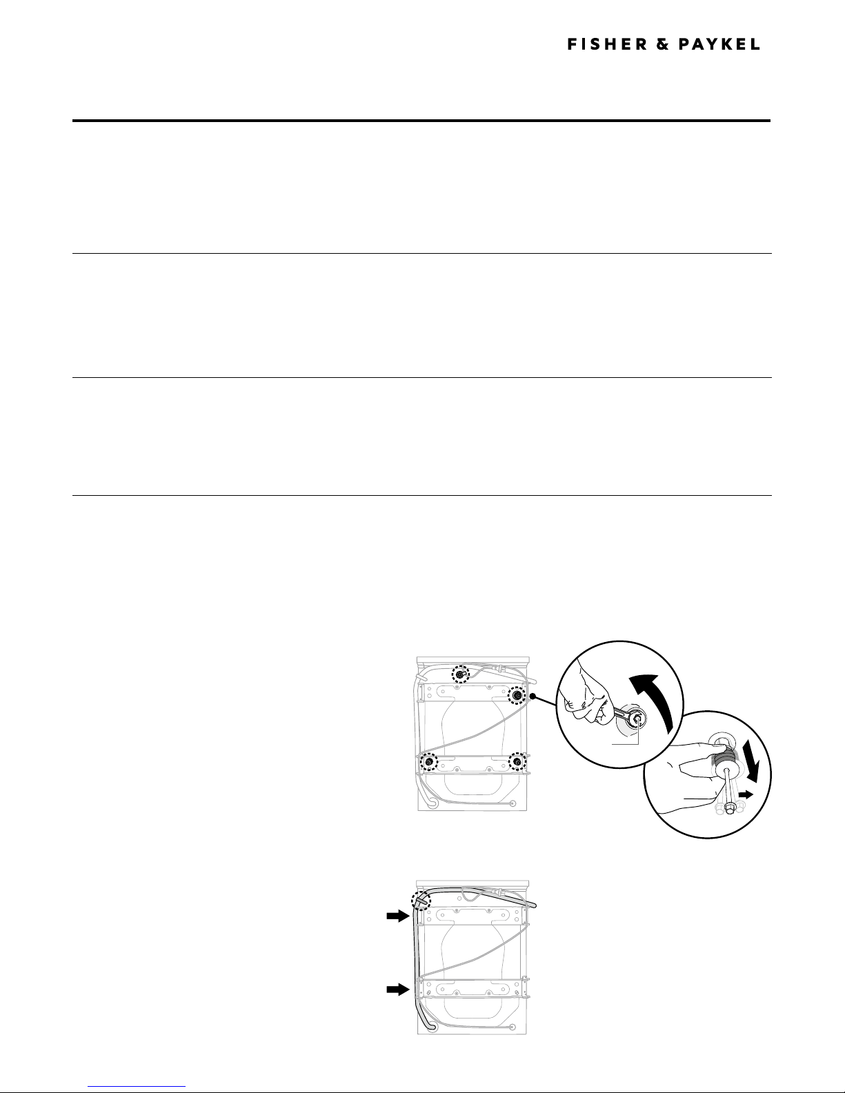
Move the drain hose from the from the plastic clasp and
clasps on the side of the transit braces.
Removing the drain hose
Removing transit safety bolts
The clothes washer is fitted with transit safety bolts at the rear to avoid possible damage to the interior during transportation.
IMPORTANT!
The transit bolts MUST be removed prior to operation of the machine. Failure to remove these will result in damage to the
machine.
Note: the transit bolts MUST be removed in order to use the power cord.
3 REMOVING TRANSIT SAFETY BOLTS
Removing the transit safety bolts
B
A
To remove the bolts
1
Use a spanner or socket to unscrew and remove all
4transit bolts at the back of the washer (refer to A).
2
Pull the black rubber grommets to remove the bolt,
grommet and white plastic spacers from the machine
(refer to B). Retain these for future use.
9 FINAL CHECKLIST
TO BE COMPLETED BY THE INSTALLER
Have the transit bolts been removed?
Is the drain hose threaded through the ‘U bend‘ (with no more
than 20mm extended) and hooked into your standpipe?
Is the hot hose connected to the Hot valve? Is the cold hose
connected to the Cold valve?
Is the machine correctly levelled and feet locked?
Have you performed the installation test cycle?
8 TESTING THE INSTALLATION
Check the operation of the machine using the following procedure:
1
Press ‘POWER’ and turn dial to ‘Quick’, then touch .
Check that the hoses are not leaking at the machine and tap end, while waiting until you see water appear in the drum.
2
Touch then press ‘POWER’ to stop the cycle and turn the machine off.
3
Press ‘POWER’ again, turn the dial to ‘Spin’ and touch .
4
Check the outlet hose is firmly secured in a standpipe or tub, or to a spigot and the machine pumps out and spins.
!0
FOR MORE INFORMATION
For detailed information on the features
of your washer and warranty information
If you…
have any questions or comments
need a Fisher & Paykel Authorised Repairer
to service your product
need replacement parts or accessories
want to register your product
Before you call for service or assistance…
Check the things you can do yourself including:
1
the product is correctly installed, and that it is level
2
you are familiar with its normal operation.
7 DRAIN HOSE
Drain hose placement in a stand pipe or tub
1
To guide the drain hose over the tub or standpipe the hose guide must be fitted to the drain hose.
The height of the standpipe or tub should be between 800 – 1200mm.
2
Secure the hose guide so it cannot become dislodged from the standpipe or tub.
IMPORTANT!
If the drain hose is placed on the ground or if the standpipe or tub is less than 800mm high, the
washing machine will continuously drain while being filled (siphon).
Regularly check that your standpipe or tub is free from lint or other obstructions, which may
affect how your machine works or may cause flooding.
6 INLET HOSES
1
Connect the straight ends of the inlet hoses to the taps and the elbow ends to the
corresponding machine inlet valves. The hot valve is colour coded orange to make this easier.
Tighten the inlet hose ends by hand until the hose seal makes contact with the tap sealing face
and then tighten a further half-turn. Make sure there are no kinks in the hoses.
2
Turn the taps on and check for leaks. Check for leaks again after 24hours.
Straight
(tap) end
Elbow
(machine) end
7
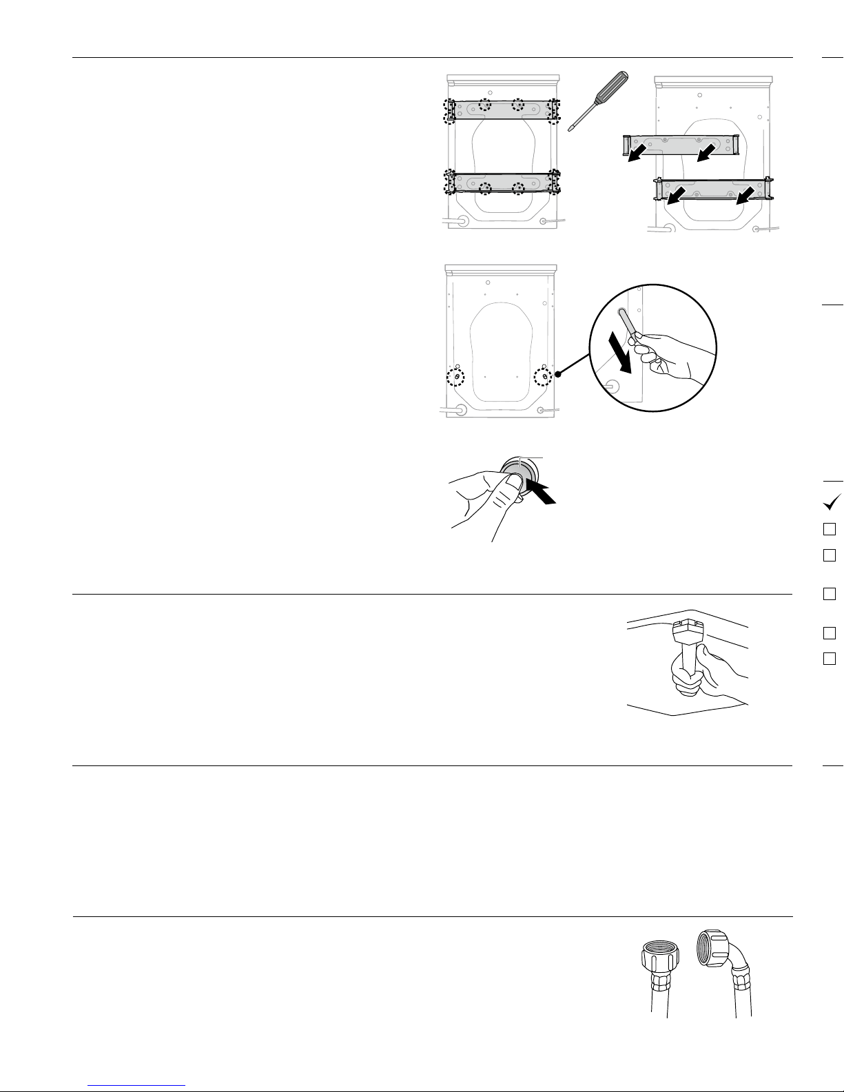
Remove the yellow safety clip from the power cord.
8
Cover the transit bolt holes with the plastic plugs (provided).
Push to clip into place (refer to F).
Covering bolt holes with plastic plugs
F
6
Remove (pull out) the two transit rods located below the two
lower transit bolt holes (refer to E).
Removing the transit rods
E
3 REMOVING TRANSIT SAFETY BOLTS CONTD...
4 LEVELLING YOUR MACHINE
1
Before positioning the machine in its final position, check that the machine is level, front to
back and side to side.
2
Manoeuvre the product into its final position (we suggest a minimum clearance of 20mm
eachside).
3
Use a spirit level to check that the machine is correctly level. If needed, pull the machine out.
Loosen the lock nut using the spanner provided and wind the feet up or down to correctly level
the machine.
4
Using the spanner provided tighten the lock nuts against the base of the machine to lock
thefeet in position.
5 CONNECTING TO THE WATER SUPPLY
IMPORTANT!
The hot water temperature should not exceed 65°C. Temperatures above this may make the machine fault or cause damage to
the machine. The cold water should not exceed 35°C.
Inlet water pressure: Maximum 1MPa(150psi), Minimum 30kPa(4.5psi).
Inlet water flow rate: Minimum 6litres/minute.
4
Remove the 12 transit brace screws from the left and right
sides, and near the centre of both the top and bottom braces
(refer to C).
5
Remove the braces (refer to D) and retain these and the
screws for future use.
Removing the braces
D
Removing the transit brace screws
C
 Loading...