

Following checks and confirmations should be taken for safety.
Check the following things by the time of the cabinet assembly after the lens
replacement.
1. Check the lens is securely fixed.
2. Check the proper wiring and the wires are fixed properly.
3. Check each connector is connected properly.
4. Check no wiring is tangled on the gear of lens motor or the other mechanical parts.
5. Check no parts is missing, or no mounting part is loose.
LCD PROJECTOR LENS
MODEL LNS-T31A/W31A/T32
LENS REPLACEMENT PROCEDURE
NOTES ON LENS REPLACEMENT
Lens replacement should be performed by the qualified service personnel.
It should be followed by this procedure precisely.
Before attempt to replace the lens, confirm the model number (both the LCD
projector and the lens) and use the proper lens.
The lens cover is on the lens for protection. Be sure to remove the lens cover
before installation.
When installing or removing the lens, be careful not to stain, scratch or
damage the lens.
If you have any questions, contact the dealers.
Following parts are contained in the packing.
1AA6P1P3188A- (ICYDA-A)
PARTS LIST
● LENS
● LIGHT-BLOCK SHEET BASE
● DRIVER (3 mm, Green)
● DRIVER (4 mm, Yellow)
● LIGHT-BLOCK SHEET For LNS-T31A
For LNS-W31A
For LNS-T32
1 piece
1 piece (Part No. 610 310 8001)
1 piece (Part No. 610 287 7328)
1 piece (Part No. 610 275 6029)
1 piece Type PB1 (Part No. 610 310 7950)
1 piece Type PC1 (Part No. 610 310 7967)
1 piece Type PF1 (Part No. 610 310 7974)
NOTE; Lens installation is different in cabinet design and lens attachment method
(Type A, B and C). Before installation the lens, check cabinet design and
proper installation should be made.
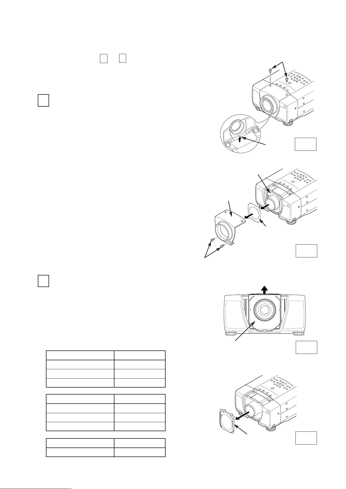
Fig-1
Fig-2
Fig-3
Fig-4
SCREW "A"
Remove 2 screws-A.
Press the button (or remove 2 screws-B) on
the lower of the lens cover and remove the
lens cover.
Remove the light-block sheet from the light-
block sheet base.
LENS REPLACEMENT PROCEDURE (FOR "A" TYPE )
REMOVE THE LENS COVER AND LIGHT-
BLOCK SHEET (See Figure-1 and 2)
1
1.
2.
2
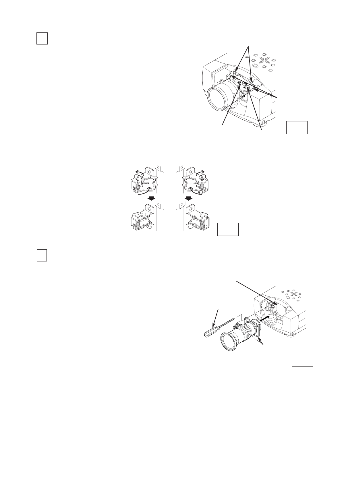
REMOVE THE LIGHT-BLOCK SHEET BASE
(See Figure-3 and 4)
Perform the steps
to
for lens replacement.
1
6
BUTTON
LENS COVER
LIGHT-BLOCK
SHEET BASE
SCREW "B" (Some models)
LIGHT-BLOCK SHEET
LIGHT-BLOCK
SHEET BASE
First set the lens at the center position with lens
shift adjustment.
3.
Slide the light-block sheet base upward.
Remove the light-block sheet base.
1.
2.
LIGHT-BLOCK
SHEET BASE
LENS MOTOR PARTS NO.
(LOCATED ON THE LENS)
LENS
MOTORASSEMBLY
ZOOMMOTOR
FOCUSMOTOR
LENS
MOTORASSEMBLY
ZOOMMOTOR
FOCUSMOTOR
LNS-T31A
6450477713
6450477157
6450477140
LNS-W31A
6450477706
6450477133
6450477126
-2-
LENS
MOTORASSEMBLY
LNS-T32
6450630323
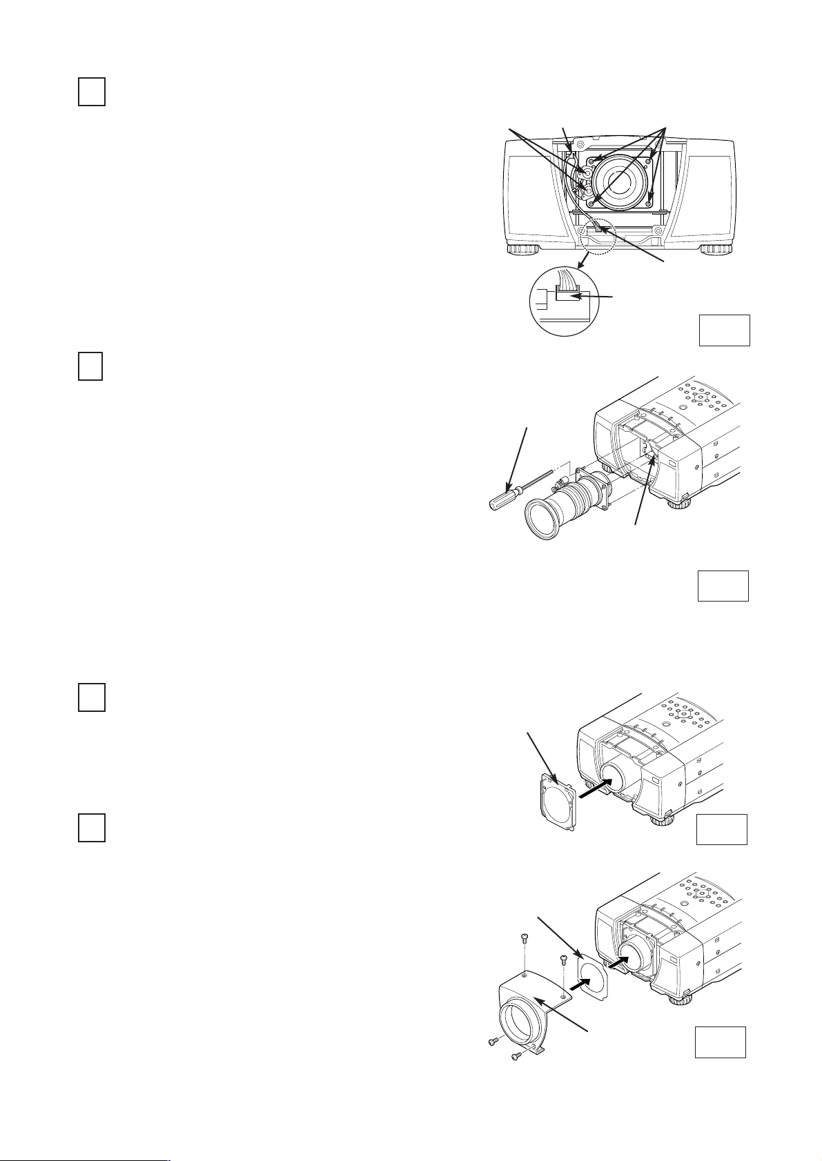
Fig-6
Fig-7
Fig-8
3
REMOVE THE LENS (See Figure-5 and 6)
Remove the connector "K16J" of the circuit board.
Remove the lens motor lead from lead holder.
Remove screws-C (4 screws) which fastens the
lens and remove the lens. Use the driver (3 mm,
Green) included with the lens to remove the
screws.
1.
2.
DRIVER
IN THE LENS
LENS MOUNTING
BRACKET
4
MOUNT THE LENS (See Figure-5 and 6)
5
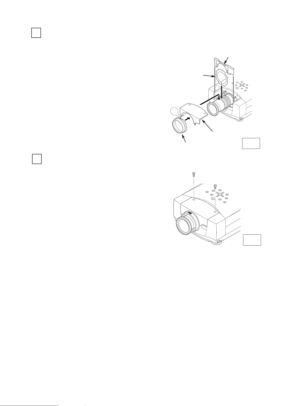
MOUNT THE LIGHT-BLOCK SHEET BASE
(See Figure-7)
6
MOUNT THE LIGHT-BLOCK SHEET AND
LENS COVER (See Figure-8)
Be careful not to drop the lens when removing the
screws.
After using, save the driver for latter use.
Remove protective caps (front and back) on the
lens.
Mount the lens on lens mounting bracket with 4
screws. (locate motor on left side).
Use the driver (4 mm, Yellow) included with the
lens to fasten the screws.
1.
2.
After using, save the driver for latter use.
Connect the lens motor lead to the connector
"K16J" of the circuit board.
Connect the lens motor lead to the lead holder.
3.
4.
Mount the light-block sheet base to the projector.
Mount the light-block sheet to the light-block sheet
base as shown in the Figure-8. (In the same
position as the removed sheet has been placed).
Use the sheet included with the lens.
Make sure the part no. and mark (TOP and BACK)
on Light-Block Sheet and set them properly.
Mount the lens cover with the screws.
1.
2.
3.
1.
LENS COVER
LIGHT-BLOCK
SHEET
LIGHT-BLOCK
SHEET BASE
(Part No. 412 062 3705)
LENS
MOTOR
LEAD
HOLDER
CONNECTOR "K16J"
LENS MOTOR LEAD
SCREW "C"
Fig-5
-3-
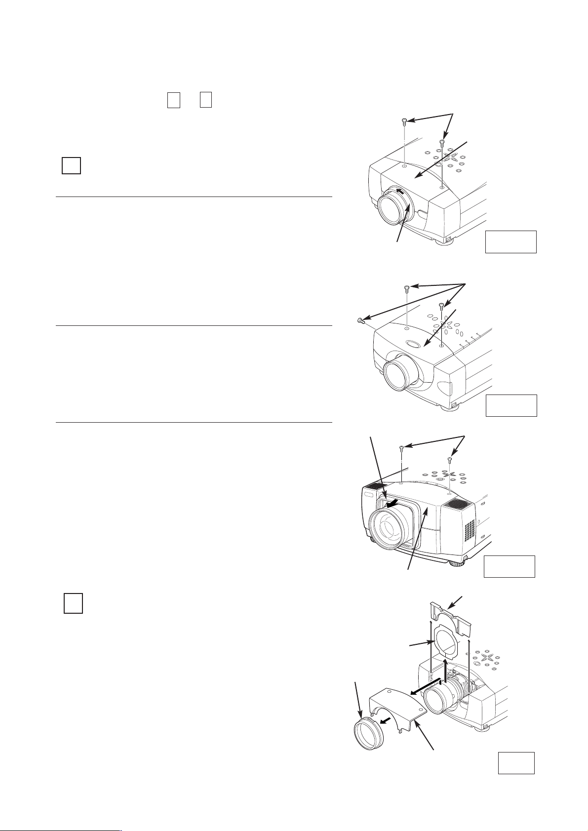
Turn the lens cover to counter-clockwise and
pull it toward front and remove the Lens
Cover.
Remove 2 Screws-A.
Remove the front cabinet
REMOVE THE LENS COVER AND
FRONT CABINET
1
1.
2.
2
REMOVE THE LIGHT-BLOCK SHEET BASE
AND LIGHT-BLOCK SHEET (See Figure-2)
Perform the steps
to
for lens replacement.
1
6
First set the lens at the fully lower position with
lens shift adjustment.
3.
Slide the light-block sheet base upward
and remove it.
Remove the light-block sheet from lens.
1.
2.
Fig-2
LIGHT-BLOCK
SHEET BASE
FRONT
CABINET
LENS COVER
LIGHT-BLOCK
SHEET
LENS REPLACEMENT PROCEDURE (FOR "B" TYPE)
SCREW "A"
SCREW "A"
SCREW "A"
Fig-1-1
Fig-1-2
Fig-1-3
Remove 2 Screws-A.
Remove the front cabinet
See Figure-1-2 and 2.
1.
2.
Pull Lens Cover toward front and remove it.
Remove 2 Screws-A.
Remove the front cabinet
See Figure-1-3 and 2.
1.
2.
3.
LENS COVER
FRONT CABINET
LENS COVER
FRONT CABINET
FRONT CABINET
-4-
See Figure-1-1 and 2.
4
MOUNT THE LENS (See Figure-5)
Remove protective caps (front and back) on the
lens.
Mount the lens on lens mounting bracket with
Upper 2 screws. (locate motor on left side).
Use the driver (4 mm, Yellow) included with the
lens to fasten the screws.
Remove the lower 2 screws on the Lens. (Lower 2
screws are not used.)
Slide the lens lock latches to "LOCK" position and
lock the lens. (See Figure-4)
Connect the lens motor connector to terminal.
(See Figure-3)
1.
2.
3.
4.
DRIVER
IN THE LENS
LENS MOUNTING
BRACKET
Fig-5
Fig-3
SCREW "B"
LENS LOCK
LATCHES
CONNECTOR
3
REMOVE THE LENS (See Figure-3 and 4)
Remove the lens motor connector from terminal.
Loosen the screws-B (2 screws) which fastens
the lens. {Use the driver (4 mm, Yellow) included
with the lens to loosen the screws.}
Slide the lens lock latches to "UNLOCK" position
and remove the lens.
1.
2.
Be careful not to drop the lens when removing the
screws. After using, save the driver for latter use.
3.
TERMINAL
LENS LOCK LATCHES
LOCK
POSITION
UNLOCK
POSITION
Fig-4
LOWER SCREWS
-5-
5
MOUNT THE LIGHT-BLOCK SHEET AND
LIGHT-BLOCK SHEET BASE (See Figure-6)
6
MOUNT THE FRONT CABINET AND LENS
COVER (See Figure-6 and 7)
Mount the light-block sheet on the lens as shown
in the Figure-6. (In the same position as the
removed sheet has been placed). Use the sheet
included with the lens.
Make sure the part no. and mark (TOP and BACK)
on Light-Block Sheet and set them properly.
Mount the light-block sheet base included with the
lens.
1.
2.
3.
LIGHT-BLOCK
SHEET BASE
FRONT
CABINET
LENS COVER
LIGHT-BLOCK
SHEET
Mount the front cabinet with 2 screws.
Mount the lens cover.
For the cabinet Fig. 1-1, position the marked UP of
Lens Cover on top and push in to the front cabinet
and turn the Lens Cover fully clockwise until it is
properly locked.
For the cabinet Fig. 1-3, push the Lens Cover onto
the cabinet
1.
2.
Fig-7
-6-
Fig-6
UP

- 7 -
Turn the lens cover to counter-clockwise and pull it
toward front and remove the Lens Cover.
Remove 2 Screws-A.
Remove the front cabinet
REMOVE THE LENS COVER AND
FRONT CABINET
1
1.
2.
2
REMOVE THE LIGHT-BLOCK SHEET BASE
AND LIGHT-BLOCK SHEET
Perform the steps
to
for lens replacement.
1
6
First set the lens at the fully lower position with lens
shift adjustment.
3.
Slide the light-block sheet base upward and
remove it.
Remove the light-block sheet from lens.
1.
2.
LIGHT-BLOCK
SHEET BASE
FRONT
CABINET
LENS COVER
LIGHT-BLOCK
SHEET
SCREW "A"
LENS COVER
FRONT CABINET
3
REMOVE THE LENS
Grasp the Lens Lock Lever and turn it fully
upward. Remove the Lens into the projector.
Disconnect the lens motor lead connector to the
socket on the lens attachment.
Remove 4 Screws and remove lens attachment.
1.
2.
3.
LENS
ATTACHMENT
SOCKET
CONNECTOR
LENS MOTOR
LEAD
LENS LOCK
LEVER
SCREW
Pull the Lens
Lock Lever
upward
LENS REPLACEMENT PROCEDURE (FOR "C" TYPE )

- 8 -
LENS
ATTACHMENT
Part No. (610 275 6029)
4
MOUNT THE LENS
Remove protective caps (front and back) on the optional lens.
Mount the lens on the lens attachment with 4 Screws.
Connect the lens motor lead connector to the socket on the lens attachment. (Motor Driven
Lens only.)
Grasp the Lens Lock Lever and turn it fully upward. Install the Lens into the projector. Turn
the Lens Lock Lever fully downward until lever is Locked (clicked position) properly.
When installing the Motor Driven Lens, be sure to mount Lens Motor on left-side.
After installing the lens, make sure the Lens is not loose and properly installed.
1.
2.
3.
4.
Push the Lens
Lock Lever fully
downward until it is
locked (clicked).
DRIVER
IN THE LENS
LENS
ATTACHMENT
SOCKET
CONNECTOR
LENS MOTOR
LEAD
LENS LOCK LEVER
LENS LOCK LEVER
SCREW
When the lens is attached to the projector and
images are being projected onto the screen, the
peripheral focus may be out of focus in some
localized areas. If this happens, insert the spacer
in between the lens attachment and the lens to
correct the focus.
Correcting the focus
Spacer "1"
Color; Clear
Thickness; 0.1 mm
40-inch projection
Screen
Inserting the spacers corrects the distance for best
diagonal focus at the screen.
The corrected distance is determined by the
thickness of the spacers that are used. As a guide,
the distance is adjusted by approximately 30 mm
for each 0.1-mm thickness of the spacers.
There are three types of spacers provided, and
there are four of each spacer type. Use these
spacers to correct the distance as required.
C
D
A
B
Distance
Spacer "2"
Color; Black
Thickness; 0.2 mm
Spacer "1"
Color; Cream
Thickness; 0.3 mm
Correction distance
30 mm/for 40-inch
projection
Correction distance
55 mm/for 40-inch
projection
Correction distance
80 mm/for 40-inch
projection
SPACER
A
B
C
D
A~D
Insertion position
of the focus
correction spacers.
Refer to following.
Insert spacers in
the location A~D
(above figure)
corresponding to
the screen location
A~D.
Screen

- 9 -
5
MOUNT THE LIGHT-BLOCK SHEET AND
LIGHT-BLOCK SHEET BASE
6
MOUNT THE FRONT CABINET AND LENS
COVER
Mount the light-block sheet on the lens. (In the same
position as the removed sheet has been placed). Use
the sheet included with the lens.
Make sure the mark (TOP and BACK) on Light-Block
Sheet and set them properly.
Mount the light-block sheet base included with the
lens.
1.
2.
LIGHT-BLOCK
SHEET BASE
FRONT
CABINET
LENS COVER
LIGHT-BLOCK
SHEET
Mount the front cabinet with 2 screws.
Mount the lens cover.
Position the marked UP of Lens Cover on top and
push in to the front cabinet and turn the Lens Cover
fully clockwise until it is properly locked.
1.
2.
UP

液晶プロジェクターレンズ
品番 LNS-T31A/W31A/T32
レンズ交換作業手順書
交換作業上の注意
レンズ交換はサ−ビス技術員が行ってください。
レンズ交換はこの作業手順書に従い、正しく行ってください。
レンズ交換のまえに、液晶プロジェクターの品番と交換レンズの品番をよく確
認のうえ、正しい品番のレンズをご使用ください。
レンズにはレンズ保護のためのキャップが付いています。レンズを取り付ける
まえに、かならずキャップを外してください。
レンズの取り付け、取り外しのとき、レンズ表面を手でさわったり傷を付けた
りしないようご注意ください。
適合レンズの詳しくは取扱販売店にご相談ください。
部品明細
梱包にはつぎの部品が入っています。
・レンズ本体
・遮光プレートベース
・専用ドライバー (3mm、 緑色)
・専用ドライバー (4mm、 黄色)
・遮光板 (LNS-T31A用)
(LNS-W31A用)
(LNS-T32用)
1AA6P1P3188A-(ICYDA-A)
1個
1個 (品番 6103108001)
1本 (品番 6102877328)
1本 (品番 6102756029)
1枚 型番 PB1(品番 6103107950)
1枚 型番 PC1(品番 6103107967)
1枚 型番 PF1(品番 6103107974)
安全のため、必ずつぎの点検と確認を行ってください。
レンズ交換のあと、キャビネットを組み立てるまえに、つぎの点検を行ってくだ
さい。
1.レンズがしっかり固定されているか。
2.配線が正しく行われているか、また配線の整形が正しく行われているか。
3.各接続コネクターは、しっかりはまっているか。
4.配線がレンズモーターのギヤーおよびその他のメカ部品にからまっていないか。
5.外れている部品はないか。
注意;このレンズはキャビネットの形状およびレンズ取り付け部によって取り付け
方法が異なります。(Aタイプ、Bタイプ、Cタイプ)
はじめにキャビネットの形状およびレンズ取り付け部をお確かめください。

レンズ交換は
スクリューA(2本)を外します。
レンズカバー下部のボタンを矢印の方向に押し、{モデルに
よってはレンズカバー下部のスクリューB (2本)を外しま
す。} レンズカバーを外します。
遮光プレートを遮光プレートベースより取り外します。
レンズ交換のしかた (Aタイプへの取り付け)
レンズカバー及び遮光プレートを外す。
(図 1、2参照)
1
1.
2.
1 6
〜
2
の手順で行います。
遮光プレートベースを外す。(図 3、4参照)
遮光プレートベースを上方にスライドさせます。
遮光プレートベースを手前に取り外します。
1.
2.
はじめにレンズシフトでレンズを移動範囲の中央にします。
3.
図1
図2
図3
図4
スクリュー "A"
ボタン
スクリュー "B"
レンズカバー
遮光プレート
遮光プレートベース
遮光プレートベース
遮光プレートベース
レンズに付随のモーターの品番
レンズ
モーターアセンブリー
ズームモーター
フォーカスモーター
レンズ
モーターアセンブリー
ズームモーター
フォーカスモーター
LNS-T31A
6450477713
6450477157
6450477140
LNS-W31A
6450477706
6450477133
6450477126
-2-
レンズ
モーターアセンブリー
LNS-T32
6450630323

3
レンズを外す。(図 5、6参照)
基板のコネクター "K16J"を外します。
レンズモーターのリードを上部ホルダーより外します。
レンズを固定しているスクリューC(4本)を外し、レン
ズを外します。 スクリューの取り外しは付属の専用ドラ
イバ−(3mm、緑色)をご使用ください。
1.
2.
スクリューを外すとき、レンズを落下させないようご注意く
ださい。
ドライバーはご使用になったあと、大切に保存してください。
後でレンズの取り付け、取り外しのとき必要です。
図5
図6
図7
図8
4
レンズを取り付ける。(図 5、6参照)
交換レンズに付いているレンズ保護キャップ(前後2箇所)
を外します
レンズをレンズマウントブラケットへレンズに付属のス
クリュー(4本)で取り付けます。(モーターを左側にし
て取り付けます。)
スクリューの締め付けは付属の専用ドライバ−(4mm、
黄色)をご使用ください。
1.
2.
ドライバーはご使用になったあと、大切に保存してください。
後でレンズの取り付け、取り外しのとき必要です。
5
遮光プレートベースを取り付ける。(図 7参照)
レンズモータのコネクターをレンズ下にあるプリント基
板のコネクター"K16J"に接続します。
モーターリードをレンズ上方にあるホルダーにかけます。
3.
4.
で外した遮光プレートベースを取り付ける。
2.
6
遮光プレート及びレンズカバーを取り付ける。
(図 8参照)
交換レンズに同梱されている遮光プレートをレンズに通
し遮光プレートベースに取り付けます。(もと付いていた
遮光プレートと同じ位置に取り付けます)。
遮光プレートには取り付け方向が表示されています。
THISSIDEBACKを 後方に、TOPを上側に取り付けま
す。
レンズカバーをスクリュー(2本 もしくは 4本)で取り
付ける。
1.
2.
3.
ホルダー
レンズモーター
レンズモーターリード
コネクター "K16J"
専用ドライバー
レンズマウントブラケット
レンズカバー
遮光プレート
遮光プレートベース
スクリュー "C"
(品番 4120623705)
-3-

レンズ交換は
レンズカバーを矢印の方向に回し手前に引っ張り、レンズカ
バーを取り外します。
スクリューA(2本)を外します。
前面キャビネットを取り外します。
レンズ交換のしかた (Bタイプへの取り付け)
レンズカバー及び前面キャビネットを外す。
1
1.
2.
1 6
〜
2
の手順で行います。
遮光プレートベース及び遮光プレートを外す。
(図 2 参照)
遮光プレートベースを上方にスライドさせ取り外します。
遮光プレートを取り外します。
1.
2.
はじめにレンズシフトでレンズを一番下までさげます。
図 1-1
スクリュー "A"
3.
図2
遮光プレート
遮光プレートベース
前面キャビネット
レンズカバー
図 1-2
スクリュー "A"
図 1-3
スクリュー "A"
スクリューA(3本)を外します。
前面キャビネットを取り外します。
(図 1ー2、2 参照)
1.
2.
レンズカバーを手前に引っ張り取り外します。
スクリューA(2本)を外します。
前面キャビネットを取り外します。
(図 1ー3、2 参照)
1.
2.
3.
前面キャビネット
前面キャビネット
前面キャビネット
レンズカバー
レンズカバー
-4-
(図 1ー1、2 参照)

4
レンズを取り付ける。(図 5参照)
交換レンズに付いているレンズ保護キャップ(前後2箇所)
を外します
レンズをレンズマウントブラケットへレンズに付属のスク
リュー(上側2本)で取り付けます。(モーターを左側にし
て取り付けます。) 下側の2本のスクリューはレンズ取
り付けには不要ですので取り外します。
{付属の専用ドライバ−(4mm,黄色)をご使用ください}。
レンズ両側の固定金具を固定側にスライドさせ、レンズを
固定します。(図4参照)
レンズモータのコネクターを中継ターミナルに接続しま
す。(図3参照)
1.
2.
3.
4.
図5
レンズマウントブラケット
専用ドライバ−
3
レンズを外す。(図 3、4参照)
レンズモーターのコネクター を中継タ−ミナルより外しま
す。
レンズを固定しているスクリューB(2本)を緩めます。
{付属の専用ドライバ−(4mm,黄色)をご使用ください}。
レンズ両側の固定金具を解除側にスライドさせ、レンズ
を
取り外します。
1.
2.
レンズを落下させないようご注意ください。
ドライバーはご使用になったあと、大切に保存してください。
後でレンズの取り付け、取り外しのとき必要です。
図3
図4
スクリュー "B"
レンズ
固定金具
レンズ固定金具
固定側
コネクター
解除側
3.
中継ターミナル
スクリュー(下側)
を取り外す。
-5-

図6
図7
5
6
遮光プレート及び遮光プレートベースを取り付
ける。(図 6参照)
交換レンズに同梱されている遮光プレートをレンズに通し
ます。
遮光プレートには取り付け方向が表示されています。
THISSIDEBACKを 後方に、TOPを上側に取り付けます。
交換レンズに同梱されている遮光プレートベースを取り付
けます。(もと付いていた遮光プレートベースと同じ位置
に取り付けます)。
1.
2.
前面キャビネットをスクリュー(2本)で取り付ける。
レンズカバーを前面キャビネットに取り付ける。
図1ー1のレンズカバーは凹部にUPの記載のある部分を上側
にし、前面キャビネットに差し込み、レンズカバーが止ま
るまで右一杯に回し、レンズカバーをしっかり固定します。
図1ー3のレンズカバーは前面より押し込んで取り付けます。
1.
2.
前面キャビネット及びレンズカバーを取り付け
る。(図 6、7参照)
遮光プレート
遮光プレートベース
前面キャビネット
レンズカバー
-6-
UP

-7 -
レンズ交換は
レンズカバーを矢印の方向に回し手前に引っ張り、レンズカ
バーを取り外します。
スクリューA(2本)を外します。
前面キャビネットを取り外します。
レンズカバー及び前面キャビネットを外します。
1
1.
2.
1 6
〜
2
の手順で行います。
遮光プレートベース及び遮光プレートを外します。
遮光プレートベースを上方にスライドさせ取り外します。
遮光プレートを取り外します。
1.
2.
はじめにレンズシフトでレンズを一番下までさげます。
スクリュー "A"
3.
遮光プレート
遮光プレートベース
前面キャビネット
レンズカバー
前面キャビネット
レンズカバー
3
レンズを外します。
1.
2.
3.
レンズを支えながらプロジェクターのレンズロックレバ
ーを解除し(レバーを
上方にスライドさせる)プロジェ
クター本体からレンズを取り外します。
レンズモーターリードのコネクターをレンズアタッチ
メントのソケットより取り外します。
レンズを固定しているスクリュー(4本)を緩めてレ
ンズをレンズアタッチメントより取り外します。
ソケット
レンズモーターリード
レンズアタッチメント
コネクター
タブをつまん
で上げ
る。
レンズロックレバー
スクリュー
解除
レンズ交換のしかた (Cタイプへの取り付け)

-8 -
レンズに付属の
ドライバー
レンズアタッチメント
品番 (6102756029)
レンズロックレバー
タブをつまん
で下げ
る。
4
レンズを取り付けます。
交換レンズを
1.
2.
3.
4.
ソケット
レンズモーターリード
レンズアタッチメント
コネクター
レンズロックレバー
交換レンズに付いているレンズ保護キャップ(前後2箇所)を外します
レンズモーターリードのコネクターをレンズアタッチメントのソケットに接続します。
プロジェクターのレンズロックレバーが解除されているのを確認した後、レンズアタッチメントに
取り付けたレンズをプロジェクター本体にはめ込みます。
プロジェクターのレンズロックレバーをつまみ、レンズロックレバーを下側一杯に(レバーがカチ
ッとロックするまで)下げます。(モーターを左側にして取り付けます。)
取り付け後、レンズが正しく取り付けられているか確認ください。
3
で取り外したレンズアタッチメントにスクリュー(4本)で取り付けます。
スクリュー
プロジェクターにレンズを取り付けてスクリーンに投
影した時、周辺フォーカスが局部的にずれている場合
があります。 このような場合、レンズアタッチメント
とレンズの間に付属のスペーサーを挿入しフォーカス
を補正してください。
周辺フォーカスの補正
スペーサー "1"
色 (クリア)、
厚み,0.1mm
補正距離
30mm/40インチ投影時
補正距離
55mm/40インチ投影時
補正距離
80mm/40インチ投影時
40インチ
投影
スクリーン
スペーサーを挿入することにより対角のベストフォー
カスの距離がスクリーン側に補正されます。
挿入するスペーサーの厚さにより補正距離が決定しま
す。補正距離の目安はスペーサーの厚さ0.1mmにつき
約30mmです。
スペーサーは3種類各4枚同梱されています。補正距離
に応じてスペーサーを挿入ください。
スペーサー "2"
色 (黒)、
厚み,0.2mm
スペーサー "3"
色 (クリーム)、
厚み,0.3mm
D
B
距離
C
A
スペーサー
A
B
C
D
A〜D
フォーカス補正用
スペーサー挿入位置
下記参照
フォーカス補正点
A〜Dに相当する
上図A〜Dの位置に
フォーカス補正用
スペーサーを
挿入する。
スクリーン

-9 -
5
6
遮光プレート及び遮光プレートベースを取り付
けます。
交換レンズに同梱されている遮光プレートをレンズに通し
ます。
遮光プレートには取り付け方向が表示されています。
THISSIDEBACKを 後方に、TOPを上側に取り付けます。
交換レンズに同梱されている遮光プレートベースを取り付
けます。(もと付いていた遮光プレートベースと同じ位置
に取り付けます)。
1.
2.
前面キャビネットをスクリュー(2本)で取り付けます。
レンズカバーを前面キャビネットに取り付けます。
レンズカバーは凹部にUPの記載のある部分を上側にし、前
面キャビネットに差し込み、レンズカバーが止まるまで右
一杯に回し、レンズカバーをしっかり固定します。
1.
2.
前面キャビネット及びレンズカバーを取り付け
ます。
遮光プレート
遮光プレートベース
前面キャビネット
レンズカバー
UP
 Loading...