

キャビネットの形状 (2)5ページ参照
1AA6P1P4097-- (IDLS)
液晶プロジェクターレンズ
品番 LNS-T03
レンズ交換・取付作業手順書
ご注意:レンズを取り付けるまえに
レンズはご使用になるプロジェクターのキャビネットの形状により、取付方法が異
なります。取り付けるまえにキャビネットの形状をよくお確かめのうえ、キャビネ
ットに合った取付作業手順にしたがい、正しくご使用ください。
レンズは液晶プロジェクターに適合した正しい品番のものをお使いください。詳し
くはカタログ、または販売店でお確かめください。
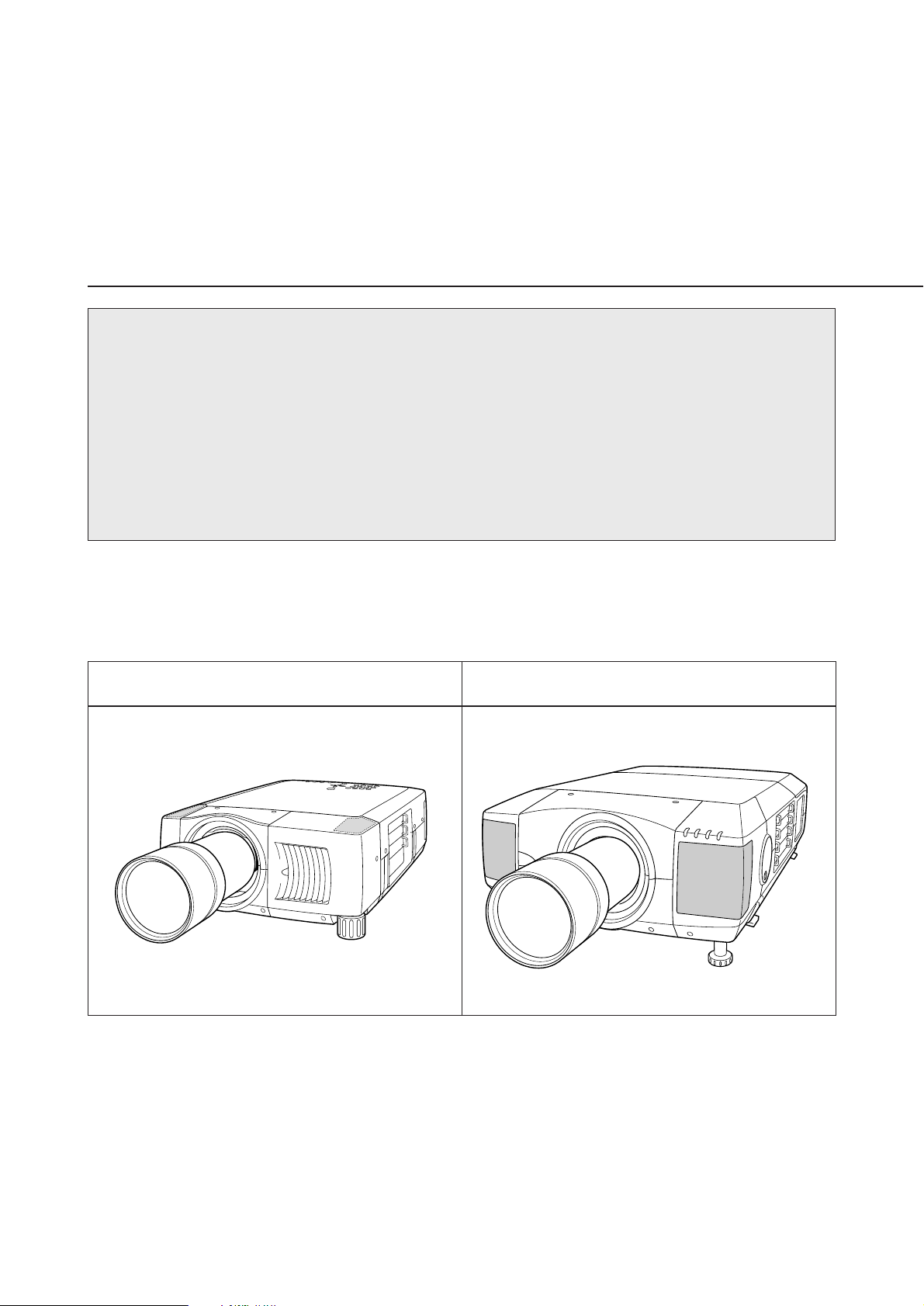
キャビネットの形状と取付作業手順
キャビネットの形状により取付作業手順が異なります。下図を参照のうえ、正しい作業
手順で行ってください。
キャビネットの形状 (1)2ページ参照
※上記形状以外の機種へのご使用については取扱販売店へご相談ください。
レンズの取り付け、または交換のあとに、お使いにならない部品が残る場合があります。
これらの部品は後日必要となる場合がありますので、大切に保管してください。
※説明文中の図は実際のものと異なる場合があります。
取り付け作業上の注意
●レンズの取り付け、交換作業はサービス技術員が行ってください。
●レンズの取り付け、交換作業はこの作業手順書にしたがい、正しく行ってくだ
さい。
●レンズにはレンズ保護のためのキャップが付いています。レンズを取り付ける
まえに、かならずキャップをはずしてください。
●レンズの取り付け、取り外しのとき、レンズの表面を手でさわったり傷を付け
たりしないようご注意ください。
レンズを取り付けたあと、レンズカバーを取り付けるまえに、つぎの点検を行って
ください。
1. レンズがしっかり固定されているか。
2. 外れている部品はないか。
安全のため、必ずつぎの点検と確認を行ってください。
部品明細
梱包には以下の部品が入っています。
・レンズ本体 1個
・専用ドライバー 1本
-1-
レンズの交換と取り付けかた {キャビネット形状 (1)の場合}
-2-
1
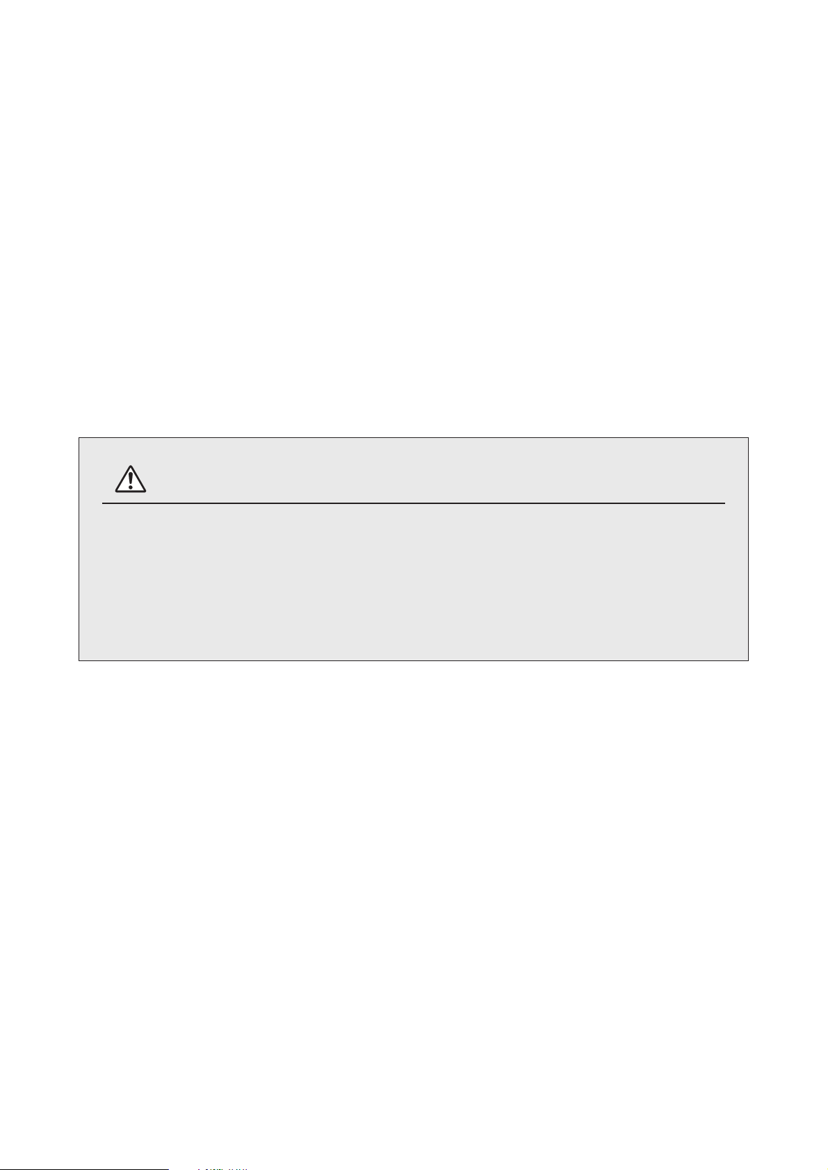
レンズカバー下のスクリューA(2本)を外し、
B部を矢印の方向に押し、レンズカバー下を下
方へ引いて外します。(図-1参照)
2
スクリューC(4本)を外し、レンズカバー上
を手前に引いて外します。(図-2参照)
3
レンズカバー上裏面のスクリューD(2本)を外
し、カバープレートを外します。(図-3参照)
図-1
レンズカバー下
A
図-2
レンズカバー上
C
C
B
D
図-3
レンズカバー上
カバ−プレ−ト
-3-
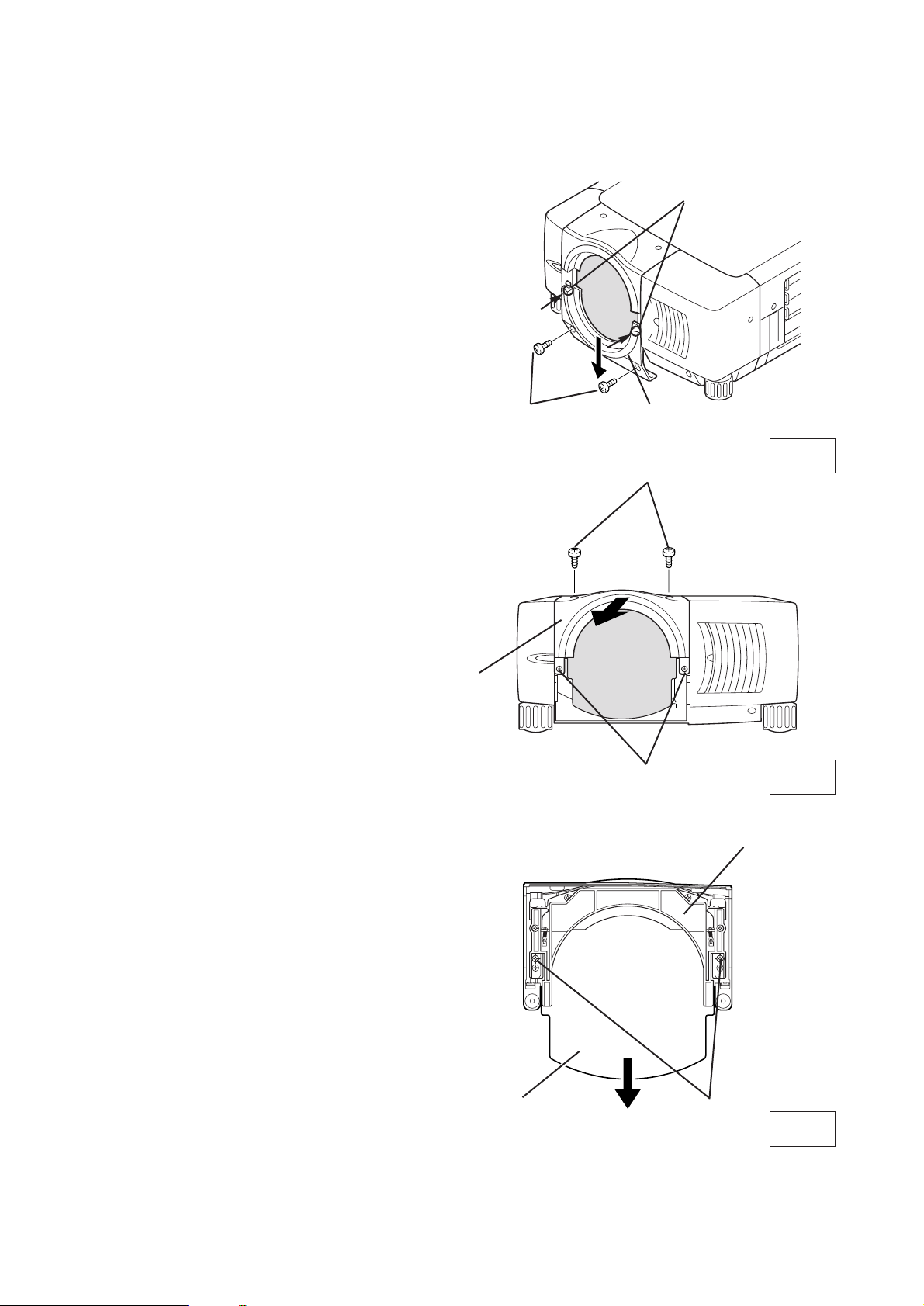
レンズに付属の
ドライバー
レンズアタッチメント
品番 (6102756029)
レンズロックレバー
レンズロックレバー 解除(上)側
レンズロックレバー 固定(下)側
5
プロジェクターのレンズロックレバーを解除し(レバータブをつまみ、レバーを上方にスライ
ドさせる)、レンズアタッチメントを取り付けたレンズをプロジェクター本体にはめ込みます。
(図-5、6参照)
プロジェクターのレンズロックレバーをつまみ、レンズロックレバーを下側一杯に(レバーが
カチッとロックするまで)下げます。(図-7参照)取り付け後、レンズが正しく取り付けられて
いるかご確認下さい。
4
レンズ後面についているレンズ保護キャップを外し、レンズへレンズアタッチメントをレンズに
付属のスクリュー(4本)で取り付けます。(図-4参照)
LensAttachement01
POA-LNA-01
(6103038742)
タブをつまん
で上げ
る。
タブをつまん
で下げ
る。
図-4
図-5
図-6
図-7
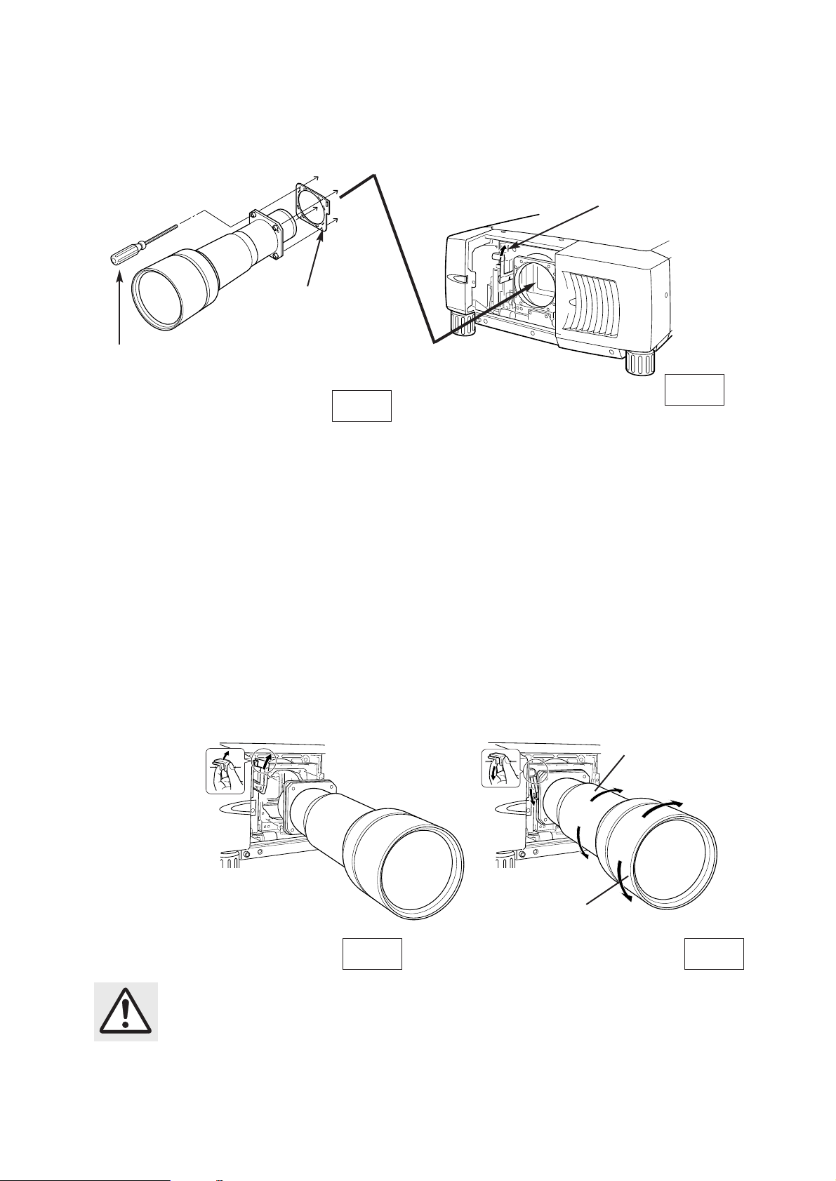
6
プロジェクターを設置場所に据え付け、電源を入れ、映像を投影します。プロジェクターの位置
を調整し、映像位置を合わせます。レンズのA部を回転させズームを調整します。 レンズのB部
を回転させフォーカスを調整します。
A部
回転させズーム
を調整します。
B部
回転させフォーカス
を調整します。
レンズの取り付け作業は必ず二人で行ってください。レンズを落としたり、
プロジェクターを破損する原因となります。
7
レンズカバー上を取り付けます。レンズカバー上のスクリューの取り付けは図-2をご参照くださ
い。レンズカバー下を取り付けます。レンズカバ−下を2本のスクリューで取り付けます。レン
ズカバー下のスクリューの取り付けは図-1をご参照ください。
レンズカバー上
レンズカバー下
図-8
-4-

レンズの交換と取り付けかた {キャビネット形状 (2)の場合}
-5-
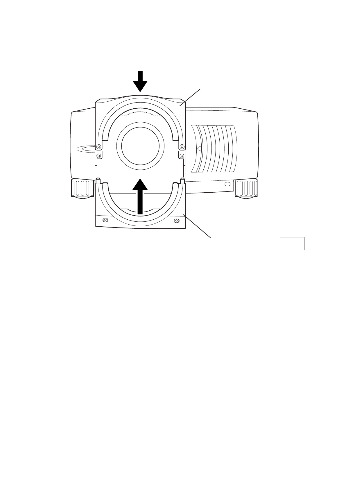
1
キャビネット前面のスクリューA(2本)を外
し、B部を矢印の方向に押し、レンズカバー上
を上方へ引いて外します。(図-1参照)
2
スクリューC(4本)を外し、レンズカバー下
を手前に引いて外します。(図-2参照)
3
レンズカバー上裏面のスクリューD(2本)を
外し、カバープレートを外します。
(図-3参照)
図-1
レンズカバー上
A
図-2
レンズカバー下
C
カバ−プレ−ト
レンズカバー上
D
図-3
B
B

-6-
5
プロジェクターのレンズロックレバーを解除側(上側)にスライドさせ、レンズアタッチメント
を取り付けたレンズをプロジェクター本体にはめ込みます。(図-5,6参照)
プロジェクターのレンズロックレバーを固定側(下側)にスライドさせレンズをしっかりと固定
させます。(図-7参照)取り付け後、レンズが正しく取り付けられているかご確認下さい。
レンズロックレバー
レンズロックレバー 解除(上)側
レンズロックレバー 固定(下)側
4
レンズ後面についているレンズ保護キャップを外し、レンズへレンズアタッチメントをレンズに
付属のスクリュー(4本)で取り付けます。(図-4参照)
図-5
タブをつまん
で上げ
る。
タブをつまん
で下げ
る。
図-6
図-7
レンズに付属の
ドライバー
レンズアタッチメント
品番 (6102756029)
LensAttachement01
POA-LNA-01
(6103038742)
図-4
6
プロジェクターを設置場所に据え付け、電源を入れ、映像を投影します。プロジェクターの位置
を調整し、映像位置を合わせます。レンズのA部を回転させズームを調整します。 レンズのB部
を回転させフォーカスを調整します。
A部
回転させズーム
を調整します。
B部
回転させフォーカス
を調整します。
レンズの取り付け作業は必ず二人で行ってください。レンズを落としたり、
プロジェクターを破損する原因となります。

-7-
7
レンズカバー下を取り付けます。レンズカバー下のスクリューの取り付けは図-2をご参照くださ
い。レンズカバー上を取り付けます。レンズカバー上のスクリューの取り付けは、図-1をご参照
ください。
図-8
レンズカバー下
レンズカバー上

Type of the Cabinet (1) (See Page 2)
LCD PROJECTOR LENS
MODEL NO. LNS-T03
LENS REPLACEMENT
AND INSTALLATION PROCEDURES
NOTES ON REPLACEMENT AND INSTALLATION
The procedures and the needed pars for lens installation depend on the type of
cabinet. Before installing or replacing the lens, make sure the type of cabinet of your
projector.
When installing or replacing the lens, make sure the Lens Model No. matches with to
your projector. Refer to the catalog, or contact your sales dealer for the proper Lens
Model No.
TYPE OF THE CABINET AND INSTALLATION PROCEDURES
Check the type of cabinet of your projector and follow the respective installation procedure
to install the lens correctly.
Type of the Cabinet (2) (See Page 5)
1AA6P1P4097-- (IDLS)
※ For lens installation to the other models than above, contact your sales dealer.

Not all the parts included may be used for lens installation or replacement. Keep these
parts for later use.
Note : Illustrations in this manual may differ from the actual product.
NOTES ON LENS INSTALLATION
• Lens installation and replacement should be made by the qualified service personnel.
• Be sure to install the lens following this procedure precisely.
• The lens cover is attached to the lens for protection. Be sure to remove the lens
cover from the lens before installation.
• When installing or replacing the lens, be careful not to stain, scratch or damage
its surface.
After installing or replacing the lens, be sure to confirm the followings for safety.
1. Make sure the lens is fixed on the projector.
2. Make sure no part is missing, or loose.
BE SURE TO CHECK THE FOLLOWING MATTERS FOR SAFETY
LIST OF CONTENTS
Following parts are included in the package.
• LENS 1 pc
• DRIVER 1 pc
-1-

LENS REPLACEMENT AND INSTALLATION PROCEDURE
{Type (1) Cabinet}
-2-
1
Remove 2 Screws A and Remove Lower Lens
Cover. Push part B and pull the Lower Lens
Cover down and remove it. (See Fig. 1.)
2
Remove 4 Screws C. Pull the Upper Lens Cover
toward front and remove it. (See Fig. 2.)
3
Remove 2 Screws D and Cover Plate from the
back of the Upper Lens Cover. (See Fig. 3.)
A
C
C
B
Fig-3
Fig-1
Fig-2
UPPER LENS
COVER
COVER PLATE
UPPER LENS
COVER
LOWER LENS
COVER
D

-3-
LENS LOCK RELEASE
Fig-4
LENS LOCK
4
Remove Lens Protection Cap from the rear (mounting side) of the Projection Lens and attach the
lens Attachment to the lens with 4 Screws. (Use screws attached to the lens.) See Fig. 4.
5
Grasp (release lock) the Lens Lock Lever and turn it fully upward. (See Fig. 6)
Mount the Lens into the lens mounting bracket and grasp the lens lock lever and turn it counter-
clockwise until the lever is locked. (See Fig. 5 and 7)
After installing the lens, make sure the lens is not loose and properly installed.
Grasp (unlock)
Lens Lock Lever
and pulling
upward.
Grasp (unlock) Lens
Lock Lever and fully
pulled downward until it
is locked (clicked).
Fig-6
Fig-7
LENS ATTACHMENT
Lens Attachment 01
POA-LNA-01
(610 303 8742)
Part No. (610 275 6029)
DRIVER INCLUDED
IN THE LENS PACKAGE
LENS LOCK
LEVER
Fig-5
LENS INSTALLATION NEEDS TWO OR MORE PEOPLE.
TO INSTALL THE LENS BY A SINGLE PERSON MAY RESULT IN A SERIOUS DAMAGE
ON THE LENS OR THE PROJECTOR BY DROPPING OR BUMPING THE PRODUCTS.
6
Set up the projector and project image on the screen. Turn the lens part "A" to adjust ZOOM. Turn
the lens part "B" to adjust FOCUS.
Turn the lens part "A"
to adjust ZOOM.
Turn the lens part "B"
to adjust FOCUS.
A
B
LENS MOUNTING
BRACKET

-4-
7
Put back the Upper Lens Cover to the projector and Fix the Upper Lens Cover with 4 Screws C.
(See Fig. 2.) Put back the Lower Lens Cover to the projector. Fix the Lower Cover with 2 Screws A.
(See Fig. 1.)
Fig-8
LOWER LENS
COVER
UPPER LENS
COVER

LENS REPLACEMENT AND INSTALLATION PROCEDURE
{Type (2) Cabinet}
-5-
2
Remove 4 Screws C. Pull the Lower Lens Cover
toward front and remove it. (See Fig. 2.)
3
Remove 2 Screws D and Cover Plate from the
back of the Upper Lens Cover. (See Fig. 3.)
Fig-1
UPPER LENS
COVER
Fig-2
LOWER LENS
COVER
C
COVER PLATE
UPPER LENS
COVER
D
Fig-3
C
B
A
1
Remove 2 Screws A and Remove Upper Lens
Cover. Push part B and pull the Upper Lens
Cover up and remove it. (See Fig. 1.)

-6-
LENS LOCK RELEASE
Part No. (610 275 6029)
Fig-4
LENS LOCK
4
Remove Lens Protection Cap from the rear (mounting side) of the Projection Lens and attach the
lens Attachment to the lens with 4 Screws. (Use screws attached to the lens.) See Fig. 4.
5
Grasp (release lock) the Lens Lock Lever and turn it fully upward. (See Fig. 6)
Mount the Lens into the lens mounting bracket and grasp the lens lock lever and turn it counter-
clockwise until the lever is locked. (See Fig. 5 and 7)
After installing the lens, make sure the lens is not loose and properly installed.
Lens Attachment 01
POA-LNA-01
(610 303 8742)
LENS ATTACHMENT
LENS LOCK
LEVER
Fig-5
Fig-6
Fig-7
Grasp (unlock) Lens
Lock Lever and fully
pulled downward until
it is locked (clicked).
Grasp (unlock)
Lens Lock Lever
and pulling
upward.
LENS INSTALLATION NEEDS TWO OR MORE PEOPLE.
TO INSTALL THE LENS BY A SINGLE PERSON MAY RESULT IN A SERIOUS DAMAGE
ON THE LENS OR THE PROJECTOR BY DROPPING OR BUMPING THE PRODUCTS.
A
B
6
Set up the projector and project image on the screen. Turn the lens part "A" to adjust ZOOM. Turn
the lens part "B" to adjust FOCUS.
Turn the lens part "A"
to adjust ZOOM.
Turn the lens part "B"
to adjust FOCUS.
DRIVER INCLUDED
IN THE LENS PACKAGE
LENS MOUNTING
BRACKET

-7-
Fig-8
LOWER LENS
COVER
UPPER LENS
COVER
7
Put back the Lower Lens Cover to the projector and Fix the Lower Lens Cover with 4 Screws C.
(See Fig. 2.) Put back the Upper Lens Cover to the projector. Fix the Upper Cover with 2 Screws A.
(See Fig. 1.)
 Loading...