


|
|
|
|
|
|
|
|
|
|
|
|
|
|
|
|
|
|
|
|
|
|
|
|
|
|
|
|
|
|
|
|
|
|
|
|
|
|
|
|
|
|
|
|
|
|
|
|
|
|
|
|
|
PN 50049:E0 |
ECN 01-106 |
Universal Digital Alarm
Communicator/Transmitter
UDACT-F
Instruction Manual
Document 50049 |
Rev: E |
01/22/2001 |
Fire Alarm System Limitations
An automatic fire alarm system–typically made up of smoke detectors, heat detectors, manual pull stations, audible warning devices, and a fire alarm control with remote notification capability–can provide early warning of a developing fire. Such a system, however, does not assure protection against property damage or loss of life resulting from a fire.
The Manufacturer recommends that smoke and/or heat detectors be located throughout a protected premise following the recommendations of the current edition of the National Fire Protection Association Standard 72 (NFPA 72), manufacturer's recommendations, State and local codes, and the recommendations contained in the Guide for Proper Use of System Smoke Detectors, which is made available at no charge to all installing dealers. A study by the Federal Emergency Management Agency (an agency of the United States government) indicated that smoke detectors may not go off in as many as 35% of all fires. While fire alarm systems are designed to provide early warning against fire, they do not guarantee warning or protection against fire. A fire alarm system may not provide timely or adequate warning, or simply may not function, for a variety of reasons:
Smoke detectors may not sense fire where smoke cannot reach the detectors such as in chimneys, in or behind walls, on roofs, or on the other side of closed doors. Smoke detectors also may not sense a fire on another level or floor of a building. A second-floor detector, for example, may not sense a first-floor or basement fire.
Particles of combustion or "smoke" from a developing fire may not reach the sensing chambers of smoke detectors because:
•Barriers such as closed or partially closed doors, walls, or chimneys may inhibit particle or smoke flow.
•Smoke particles may become "cold," stratify, and not reach the ceiling or upper walls where detectors are located.
•Smoke particles may be blown away from detectors by air outlets.
•Smoke detectors may be drawn into air returns before reaching the detector.
The amount of "smoke" present may be insufficient to alarm smoke detectors. Smoke detectors are designed to alarm at various levels of smoke density. If such density levels are not created by a developing fire at the location of detectors, the detectors will not go into alarm.
Smoke detectors, even when working properly, have sensing limitations. Detectors that have photoelectronic sensing chambers tend to detect smoldering fires better than flaming fires, which have little visible smoke. Detectors that have ion- izing-type sensing chambers tend to detect fast-flaming fires better than smoldering fires. Because fires develop in different ways and are often unpredictable in their growth, neither type of detector is necessarily best and a given type of detector may not provide adequate warning of a fire.
Smoke detectors cannot be expected to provide adequate warning of fires caused by arson, children playing with matches (especially in bedrooms), smoking in bed, and violent explosions (caused by escaping gas, improper storage of flammable materials, etc.).
While a fire alarm system may lower insurance rates, it is not a substitute for fire insurance!
Heat detectors do not sense particles of combustion and alarm only when heat on their sensors increases at a predetermined rate or reaches a predetermined level. Rate-of-rise heat detectors may be subject to reduced sensitivity over time. For this reason, the rate-of-rise feature of each detector should be tested at least once per year by a qualified fire protection specialist. Heat detectors are designed to protect property, not life.
IMPORTANT! Smoke detectors must be installed in the same room as the control panel and in rooms used by the system for the connection of alarm transmission wiring, communications, signaling, and/or power. If detectors are not so located, a developing fire may damage the alarm system, crippling its ability to report a fire.
Audible warning devices such as bells may not alert people if these devices are located on the other side of closed or partly open doors or are located on another floor of a building. Any warning device may fail to alert people with a disability or those who have recently consumed drugs, alcohol or medication. Please note that:
•Strobes can, under certain circumstances, cause seizures in people with conditions such as epilepsy.
•Studies have shown that certain people, even when they hear a fire alarm signal, do not respond or comprehend the meaning of the signal. It is the property owner's responsibility to conduct fire drills and other training exercise to make people aware of fire alarm signals and instruct them on the proper reaction to alarm signals.
•In rare instances, the sounding of a warning device can cause temporary or permanent hearing loss.
A fire alarm system will not operate without any electrical power. If AC power fails, the system will operate from standby batteries only for a specified time and only if the batteries have been properly maintained and replaced regularly.
Equipment used in the system may not be technically compatible with the control. It is essential to use only equipment listed for service with your control panel.
Telephone lines needed to transmit alarm signals from a premise to a central monitoring station may be out of service or temporarily disabled. For added protection against telephone line failure, backup radio transmission systems are recommended.
The most common cause of fire alarm malfunction is inadequate maintenance. To keep the entire fire alarm system in excellent working order, ongoing maintenance is required per the manufacturer's recommendations, and UL and NFPA standards. At a minimum, the requirements of Chapter 7 of NFPA 72 shall be followed. Environments with large amounts of dust, dirt or high air velocity require more frequent maintenance. A maintenance agreement should be arranged through the local manufacturer's representative. Maintenance should be scheduled monthly or as required by National and/ or local fire codes and should be performed by authorized professional fire alarm installers only. Adequate written records of all inspections should be kept.
LimWarLg.p65 01/10/2000

Installation Precautions
WARNING - Several different sources of power can be connected to the fire alarm control panel. Disconnect all sources of power before servicing. Control unit and associated equipment may be damaged by removing and/or inserting cards, modules, or interconnecting cables while the unit is energized. Do not attempt to install, service, or operate this unit until this manual is read and understood.
CAUTION - System Reacceptance Test after Software Changes. To ensure proper system operation, this product must be tested in accordance with NFPA 72 Chapter 7 after any programming operation or change in site-specific software. Reacceptance testing is required after any change, addition or deletion of system components, or after any modification, repair or adjustment to system hardware or wiring.
All components, circuits, system operations, or software functions known to be affected by a change must be 100% tested. In addition, to ensure that other operations are not inadvertently affected, at least 10% of initiating devices that are not directly affected by the change, up to a maximum of 50 devices, must also be tested and proper system operation verified.
This system meets NFPA requirements for operation at 0-49° C/32-120° F and at a relative humidity of 85% RH (noncondensing) at 30° C/86° F. However, the useful life of the system's standby batteries and the electronic components may be adversely affected by extreme temperature ranges and humidity. Therefore, it is recommended that this system and all peripherals be installed in an environment with a nominal room temperature of 15-27° C/60-80° F.
Verify that wire sizes are adequate for all initiating and indicating device loops. Most devices cannot tolerate more than a 10% I.R. drop from the specified device voltage.
Adherence to the following will aid in problem-free installation with long-term reliability:
Like all solid state electronic devices, this system may operate erratically or can be damaged when subjected to light- ning-induced transients. Although no system is completely immune from lightning transients and interferences, proper grounding will reduce susceptibility. Overhead or outside aerial wiring is not recommended, due to an increased susceptibility to nearby lightning strikes. Consult with the Technical Services Department if any problems are anticipated or encountered.
Disconnect AC power and batteries prior to removing or inserting circuit boards. Failure to do so can damage circuits.
Remove all electronic assemblies prior to any drilling, filing, reaming, or punching of the enclosure. When possible, make all cable entries from the sides or rear. Before making modifications, verify that they will not interfere with battery, transformer, and printed circuit board location.
Do not tighten screw terminals more than 9 in-lbs. Over-tightening may damage threads, resulting in reduced terminal contact pressure and difficulty with screw terminal removal.
Though designed to last many years, system components can fail at any time. This system contains static-sensitive components. Always ground yourself with a proper wrist strap before handling any circuits so that static charges are removed from the body. Use static-suppressive packaging
to protect electronic assemblies removed from the unit.
Follow the instructions in the installation, operating, and programming manuals. These instructions must be followed to avoid damage to the control panel and associated equipment. FACP operation and reliability depend upon proper installation by authorized personnel.
FCC Warning
WARNING: This equipment generates, uses, and can |
Canadian Requirements |
|
radiate radio frequency energy and if not installed and |
This digital apparatus does not exceed the Class A |
|
used in accordance with the instruction manual, may |
limits for radiation noise emissions from digital |
|
cause interference to radio communications. It has |
apparatus set out in the Radio Interference Regulations |
|
been tested and found to comply with the limits for class |
of the Canadian Department of Communications. |
|
A computing device pursuant to Subpart B of Part 15 of |
Le present appareil numerique n'emet pas de bruits |
|
FCC Rules, which is designed to provide reasonable |
||
radioelectriques depassant les limites applicables aux |
||
protection against such interference when operated in a |
||
appareils numeriques de la classe A prescrites dans le |
||
commercial environment. Operation of this equipment in |
||
Reglement sur le brouillage radioelectrique edicte par le |
||
a residential area is likely to cause interference, in which |
||
ministere des Communications du Canada. |
||
case the user will be required to correct the interference |
||
|
||
at his own expense. |
|
LimWarLg.p65 01/10/2000

This digital communicator has been designed to comply with standards set forth by the following regulatory agencies:
•Underwriters Laboratories Standard UL 864
•NFPA 72 National Fire Alarm Code
•CAN/ULC - S527M Standard for Control Units for Fire Alarm Systems
Before proceeding, the installer should be familiar with the following documents.
NFPA Standards
This digital communicator complies with the following NFPA Standards:
NFPA 72 National Fire Alarm Code for Central Station Signaling Systems Protected Premises Unit (Automatic, Manual and Waterflow), Local Fire Alarm Systems (Automatic, Manual, Waterflow and Sprinkler Supervisory), Proprietary Fire Alarm Systems (Protected Premises Unit), Automatic Fire Detectors, Installation, Maintenance and Use of Notification Appliances for Fire Alarm Systems and Inspection, Testing and Maintenance for Fire Alarm Systems.
FM Approved (with Ademco 685 Receiver)
Underwriters Laboratories Documents:
UL 38 Manually Actuated Signaling Boxes
UL 217 Smoke Detectors, Single and Multiple Station
UL 228 Door Closers–Holders for Fire Protective Signaling Systems
UL 268 Smoke Detectors for Fire Protective Signaling Systems
UL 268A Smoke Detectors for Duct Applications
UL 346 Waterflow Indicators for Fire Protective Signaling Systems
UL 464 Audible Signaling Appliances
UL 521 Heat Detectors for Fire Protective Signaling Systems
UL 864 Standard for Control Units for Fire Protective Signaling Systems
UL 1481 Power Supplies for Fire Protective Signaling Systems
UL 1638 Visual Signaling Appliances
UL 1971 Signaling Devices for Hearing Impaired
CAN/ULC - S524M Standard for Installation of Fire Alarm Systems
Other:
NEC Article 250 Grounding
NEC Article 300 Wiring Methods
NEC Article 760 Fire Protective Signaling Systems
Applicable Local and State Building Codes
C22.1, Canadian Electrical Code, Part I
C22.2 No. 0, General Requirements - Canadian Electrical Code, Part II
C22.2 No. 0.4, Bonding and Grounding of Electrical Equipment (Protective Grounding) - Canadian
C282, Emergency Electrical Power Supply for Buildings - Canadian
Requirements of the Local Authority Having Jurisdiction (LAHJ)
Fire•Lite Documents
Fire•Lite Device Compatibility Document |
Document #15384 |
4 |
Document #50049 Rev. E0 01/22/01 P/N 50049:E0 |

Table of Contents
CHAPTER 1: Product Description ......................................................................................................................... |
7 |
1.1: Product Features.......................................................................................................................................... |
7 |
FIGURE 1-1: UDACT-F Assembly .................................................................................................... |
8 |
1.2: Controls and Indicators ............................................................................................................................... |
9 |
FIGURE 1-2: Controls and Indicators ................................................................................................. |
9 |
1.3: Compatible Panels....................................................................................................................................... |
9 |
1.4: Digital Communicator................................................................................................................................. |
9 |
1.5: Circuits ........................................................................................................................................................ |
10 |
1.5.1: Power Requirements ......................................................................................................................... |
10 |
1.5.2: Communications ............................................................................................................................... |
10 |
1.5.3: Primary and Secondary Phone Lines ................................................................................................ |
10 |
1.5.4: Communicator Fail Relay Driver...................................................................................................... |
10 |
1.5.5: Earth Ground..................................................................................................................................... |
10 |
1.6: Specifications .............................................................................................................................................. |
10 |
1.7: Telephone Requirements and Warnings ...................................................................................................... |
11 |
1.7.1: Telephone Circuitry - PH1 & PH2 .................................................................................................... |
11 |
1.7.2: Digital Communicator....................................................................................................................... |
11 |
1.7.3: Telephone Company Rights and Warnings: ...................................................................................... |
11 |
1.7.4: For Canadian Applications................................................................................................................ |
12 |
1.8: Modes and Special Functions...................................................................................................................... |
13 |
1.8.1: Normal Mode .................................................................................................................................... |
13 |
1.8.2: Program Mode................................................................................................................................... |
13 |
1.8.3: Lamp Test Mode ............................................................................................................................... |
13 |
1.8.4: Troubleshoot Mode ........................................................................................................................... |
13 |
1.8.5: Type Mode......................................................................................................................................... |
13 |
1.8.6: Clear Function................................................................................................................................... |
13 |
1.8.7: Manual Test Function........................................................................................................................ |
13 |
CHAPTER 2: Installation......................................................................................................................................... |
14 |
2.1: Mounting Options ...................................................................................................................................... |
14 |
FIGURE 2-1: ABS-8RF....................................................................................................................... |
14 |
2.2: Panel Mounting ........................................................................................................................................... |
14 |
2.2.1: MS-9200............................................................................................................................................ |
14 |
FIGURE 2-2: UDACT-F Mounting to MS-9200 ................................................................................ |
14 |
FIGURE 2-3: External UDACT-F Mounting in ABS-8RF - MS-9200............................................... |
15 |
TABLE 2-1: Annunciator LED Assignments (MS-9200) ................................................................... |
16 |
2.2.2: MS-9600............................................................................................................................................ |
17 |
FIGURE 2-4: UDACT-F Wiring to MS-9600..................................................................................... |
17 |
TABLE 2-2: Annunciator LED Assignments (MS-9600) ................................................................... |
18 |
2.2.3: Sensiscan 2000.................................................................................................................................. |
19 |
FIGURE 2-5: UDACT-F Mounting in CHS-4 .................................................................................... |
19 |
FIGURE 2-6: EIA-485 Connection Sensiscan 2000............................................................................ |
20 |
FIGURE 2-7: 24 VDC Power Connection to UDACT-F .................................................................... |
21 |
TABLE 2-3: Sensiscan 2000 Annunciator LED Assignments ............................................................ |
22 |
2.3: UL Power-limited Wiring Requirements..................................................................................................... |
23 |
FIGURE 2-8: Typical Wiring Diagram for UL Power-limited Requirements .................................... |
23 |
2.4: Output Circuits ............................................................................................................................................ |
24 |
2.4.1: Telephone Circuits ............................................................................................................................ |
24 |
FIGURE 2-9: Wiring Phone Jacks....................................................................................................... |
24 |
2.4.2: Relay Driver ...................................................................................................................................... |
25 |
FIGURE 2-10: Relay Driver Connections ........................................................................................... |
25 |
FIGURE 2-11: Monitoring for UDACT-F Trouble............................................................................. |
26 |
Document #50049 |
Rev. E0 01/22/01 P/N 50049:E0 |
5 |

Table of Contents
CHAPTER 3: Programming Instructions ............................................................................................................... |
27 |
3.1: Entering Program Mode .............................................................................................................................. |
27 |
3.2: Switch (Key) Functions ............................................................................................................................... |
28 |
FIGURE 3-1: UDACT-F Keypad ........................................................................................................ |
28 |
3.3: Programming Options ................................................................................................................................. |
28 |
TABLE 3-1: Start and End Monitoring Address ................................................................................. |
31 |
TABLE 3-2: Primary Number Event Codes - 3+1, 4+1 Express and 4+1 Standard ........................... |
34 |
TABLE 3-3: Primary Number Event Codes - 4+2 Standard and 4+2 Express.................................... |
35 |
TABLE 3-4: Ademco Contact ID Primary Number ............................................................................ |
36 |
TABLE 3-5: Secondary Number Event Codes - 3+1, 4+1 Express and 4+1 Standard ....................... |
37 |
TABLE 3-6: Secondary Number Event Codes - 4+2 Standard and 4+2 Express................................ |
38 |
TABLE 3-7: Ademco Contact ID Secondary Number ........................................................................ |
39 |
CHAPTER 4: Operating Instructions .................................................................................................................... |
40 |
4.1: Normal Mode............................................................................................................................................... |
40 |
4.1.1: Keypad Functions.............................................................................................................................. |
40 |
4.1.2: Displays............................................................................................................................................. |
41 |
FIGURE 4-1: UDACT-F Phone Connectors and LEDs ...................................................................... |
42 |
4.1.3: Normal Mode Operation ................................................................................................................... |
42 |
4.1.4: Key Report Descriptions ................................................................................................................... |
44 |
4.2: Type Mode................................................................................................................................................... |
44 |
4.2.1: Disabling of Zones or Points............................................................................................................. |
45 |
4.2.2: Zone or Point Supervisory................................................................................................................. |
45 |
4.3: Troubleshoot Mode...................................................................................................................................... |
46 |
FIGURE 4-2: Handset/Speaker Connection ........................................................................................ |
46 |
4.4: Lamp Test Mode.......................................................................................................................................... |
46 |
Appendix A: Reporting Formats .......................................................................................................................... |
47 |
TABLE A-1: Data Reporting Structure .............................................................................................. |
47 |
TABLE A-2: Letter Code Definitions for Table A-1 ......................................................................... |
48 |
TABLE A-3: Ademco Contact ID Reporting Structure ...................................................................... |
49 |
TABLE A-4: Addressable Module Reporting Structure ..................................................................... |
50 |
TABLE A-5: Zone Reporting Structure .............................................................................................. |
50 |
Appendix B: Compatible Receivers ..................................................................................................................... |
51 |
TABLE B-1: Compatible UL Listed Receivers .................................................................................. |
51 |
Appendix C: Programming Reference Sheets ..................................................................................................... |
52 |
Appendix D: Point Assignments - MS-9200 ........................................................................................................ |
56 |
Appendix E: Code Wheel Matching Point Assignments - MS-9200 ................................................................. |
57 |
Appendix F: Point Assignments - MS-9600 ......................................................................................................... |
58 |
F.1: Type Mode Programming .......................................................................................................................... |
58 |
F.1.1: For Zone Identification: ................................................................................................................... |
58 |
F.1.2: For Point Identification: ................................................................................................................... |
58 |
F.2: Event Code/Report Transmission ............................................................................................................... |
58 |
F.2.1: For Zone Reporting: ......................................................................................................................... |
58 |
F.2.2: For Point Reporting: ......................................................................................................................... |
58 |
F.3: Point Assignments ...................................................................................................................................... |
59 |
Appendix G: Zone Assignments ........................................................................................................................... |
64 |
6 |
Document #50049 |
Rev. E0 01/22/01 P/N 50049:E0 |

Product Description
CHAPTER 1 Product Description
The Universal Digital Alarm Communicator/Transmitter (UDACT-F) may be used with the Fire•Lite MS-9200, MS-9600 and Sensiscan 2000 FACPs (Fire Alarm Control Panels). The UDACT-F transmits system status to UL listed Central Station Receivers via the public switched telephone network. The UDACT-F is compact in size and may be mounted inside the host FACP or may mount externally in a separate enclosure. EIA-485 annunciator communications bus and 24 volt (nominal) connections are required. The UDACT-F is capable of reporting 198 points or 56 zones when used with the MS-9200, 636 points or 99 zones when used with the MS-9600 and 56 zones when used with the Sensiscan 2000.
1.1Product Features
•Dual telephone lines
•Dual telephone line voltage detect
•UL recognized “Dialer Runaway” prevention
• Compact in size: 6.75" (17.145 cm) x 4.25" (10.795 cm)
• Built-in programmer
•Built-in four character red 7-segment LED display
•Manual test report function
•Manual master transmission clear function
• |
Mounts either inside control panel or in separate ABS-8RF or UBS-1F enclosure |
|
• |
Communicates vital system status including: |
|
|
Independent zone/point alarm |
UBS-1F |
Independent zone/point trouble
Independent zone/point supervisory
AC (mains) power loss - programmable
Low battery and earth fault
System off-normal
12 or 24 hour test signal
Abnormal test signal per new UL requirements
Annunciation of UDACT-F troubles, including loss of phone lines, communication failure with either Central Station and total communication failure
•Troubleshoot Mode converts keypad to DTMF touchpad
•Individual LEDs for:
Power
EIA-485 loss
Manual Test
Kissoff
Comm Fail
Primary Line Seize
Secondary Line Seize
•Open collector relay driver for Total Communication Failure or UDACT-F trouble
•Real Time Clock
•Extensive transient protection
•Simple EIA-485 interface to host panel
Document #50049 Rev. E0 01/22/01 P/N 50049:E0 |
7 |

Product Features
FIGURE 1-1:UDACT-F Assembly
Primary
Phone Line
Secondary
Phone Line
Modular Cables
P/N MCBL-7 (order separately)
24 VDC power in (use power-limited source)
EIA-485 connector (use power-limited source)
Comm Fail Output |
(power-limited) |
24 VDC |
(power-limited) |
Connect to  J16 on MS-9200,
using supplied ribbon cable
8 |
|
|
|
|
|
|
|
|
|
|
|
|
|
|
|
|
|
|
|
|
|
|
|
|
|
|
|
|
|
|
|
|
|
|
|
|
|
|
|
|
|
|
|
|
|
|
|
|
|
|
|
|
|
|
|
|
|
|
|
|
|
|
|
|
|
|
|
|
|
|
|
|
|
|
|
|
|
|
|
|
|
|
|
|
|
|
|
|
|
|
|
|
|
|
|
|
|
|
|
|
|
|
|
|
|
|
|
|
|
|
|
|
|
|
|
|
|
|
|
|
|
|
|
|
|
|
|
|
|
|
|
|
|
|
|
|
|
|
|
|
|
|
|
|
|
|
|
|
|
|
|
|
|
|
|
|
|
|
|
|
|
|
|
|
|
|
|
|
|
|
|
|
|
|
|
|
|
|
|
|
|
|
|
|
|
|
|
|
|
|
|
|
|
|
|
|
|
|
|
|
|
|
|
|
|
|
|
|
|
|
|
|
|
|
|
|
|
|
|
|
|
|
|
|
|
|
|
|
|
|
|
|
|
|
|
|
|
|
|
|
|
|
|
|
|
|
|
|
|
|
|
|
|
|
|
|
|
|
|
|
|
|
|
|
|
|
|
|
|
|
|
|
|
|
|
|
|
|
|
|
|
|
|
|
|
|
|
|
|
|
|
|
|
|
|
|
|
|
|
|
|
|
|
|
|
|
|
|
|
|
|
|
|
|
|
|
|
|
|
|
|
|
|
|
|
|
|
|
|
|
|
|
|
|
|
|
|
|
|
|
|
|
|
|
|
|
|
|
|
|
|
|
|
|
|
|
|
|
|
|
|
|
|
|
|
|
|
|
|
|
|
|
|
|
|
|
|
|
|
|
|
|
|
|
|
|
|
|
|
|
|
|
|
|
|
|
|
|
|
|
|
|
|
|
|
|
|
|
|
|
|
|
|
|
|
|
|
|
|
|
|
|
|
|
|
|
|
|
|
|
|
|
|
|
|
|
|
|
|
|
|
|
|
|
|
|
|
|
|
|
|
|
|
|
|
|
|
|
|
|
|
|
|
|
|
|
|
|
|
|
|
|
|
|
|
|
|
|
|
|
|
|
|
|
|
|
|
|
|
|
|
|
|
|
|
|
|
|
|
|
|
|
|
|
|
|
|
|
|
|
|
|
|
|
|
|
|
|
|
|
|
|
|
|
|
|
|
|
|
|
|
|
|
|
|
|
|
|
|
|
|
|
|
|
|
|
|
|
|
|
|
|
|
|
|
|
|
|
|
|
|
|
|
|
|
|
|
|
|
|
|
|
|
|
|
|
|
|
|
|
|
|
|
|
|
|
|
|
|
|
|
|
|
|
|
|
|
|
|
|
|
|
|
|
|
|
|
|
|
|
|
|
|
|
|
|
|
|
|
|
|
|
|
|
|
|
|
|
|
|
|
|
|
|
|
|
|
|
|
|
|
|
|
|
|
|
|
|
|
|
|
|
|
|
|
|
|
|
|
|
|
|
|
|
|
|
|
|
|
|
|
|
|
|
|
|
|
|
|
|
|
|
|
|
|
|
|
|
|
|
|
|
|
|
|
|
|
|
|
|
|
|
|
|
|
|
|
|
|
|
|
|
|
|
|
|
|
|
|
|
|
|
|
|
|
|
|
|
|
|
|
|
|
|
|
|
|
|
|
|
|
|
|
|
|
|
|
|
|
|
|
|
|
|
|
|
|
|
|
|
|
|
|
|
|
|
|
|
|
|
|
|
|
|
|
|
|
|
|
|
|
|
|
|
|
|
|
|
|
|
|
|
|
|
|
|
|
|
|
|
|
|
|
|
|
|
|
|
|
|
|
|
|
|
|
|
|
|
|
|
|
|
|
|
|
|
|
|
|
|
|
|
|
|
|
|
|
|
|
|
|
|
|
|
|
|
|
|
|
|
|
|
|
|
|
|
|
|
|
|
|
|
|
|
|
|
|
|
|
|
|
|
|
|
|
|
|
|
|
|
|
|
|
|
|
|
|
|
|
|
|
|
|
|
|
|
|
|
|
|
|
|
|
|
|
|
|
|
|
|
|
|
|
|
|
|
|
|
|
|
|
|
|
|
|
|
|
|
|
|
|
|
|
|
|
|
|
|
|
|
|
|
|
|
|
|
|
|
|
|
|
|
|
|
|
|
|
|
|
|
|
|
|
|
|
|
|
|
|
|
|
|
|
|
|
|
|
|
|
|
|
|
|
|
|
|
|
|
|
|
|
|
|
|
|
|
|
|
|
|
|
|
|
|
|
|
|
|
|
|
|
|
|
|
|
|
|
|
|
|
|
|
|
|
|
|
|
|
|
|
|
|
|
|
|
|
|
|
|
|
|
|
|
|
|
|
|
|
|
|
|
|
|
|
|
|
|
|
|
|
|
|
|
|
|
|
|
|
|
|
|
|
|
|
|
|
|
|
|
|
|
|
|
|
|
|
|
|
|
|
|
|
|
|
|
|
|
|
|
|
|
|
|
|
|
|
|
|
|
|
|
|
|
|
|
|
|
|
|
|
|
|
|
|
|
|
|
|
|
|
|
|
|
|
|
|
|
|
|
|
|
|
|
|
|
|
|
|
|
|
|
|
|
|
|
|
|
|
|
|
|
|
|
|
|
|
|
|
|
|
|
|
|
|
|
|
|
|
|
|
|
|
|
|
|
|
|
|
|
|
|
|
|
|
|
|
|
|
|
|
|
|
|
|
|
|
|
|
|
|
|
Document #50049 Rev.E0 1/22/01 P/N 50049:E0 |
||||||||||||||||||||||||||||||||||

Controls and Indicators
1.2Controls and Indicators
Front Panel Switches |
FIGURE 1-2:Controls and Indicators |
|
|
CLEAR |
Digits 0 - 9 |
TEST |
A |
MODE |
B |
Up Arrow |
C |
Down Arrow |
D |
1st EVENT |
E |
ENTER/STORE |
F |
Displays
• EIA-485 - yellow LED
• COMM. FAIL - yellow LED
• KISS OFF - green LED
• POWER - green LED
• Four 7-Segment Displays - red
• Primary Phone Line Active - red LED
• Secondary Phone Line Active - red LED
• TEST - green LED
1.3Compatible Panels
The UDACT-F has been designed to be compatible with the following Fire•Lite control panels:
•Sensiscan 2000
•MS-9200
•MS-9600
1.4Digital Communicator
Two modular phone jacks allow easy connection to telephone lines. Modular jacks are labeled PH1 and PH2 for the Primary and Secondary phone lines. Telephone line 'Primary and Secondary Active' red LEDs are provided as well as a green 'Kissoff' LED. The integral digital communicator provides the following functions:
•Line Seizure - takes control of the phone lines disconnecting any premises phones
•Off/On Hook - perform on and off-hook status to the phone lines
•Listen for dial tone - 440 hertz tone typical in most networks
•Dialing the Central Station(s) number - default is Touch-Tone®, programmable to rotary
•For tone burst or touchtone type formats: Discern proper 'Ack' and 'Kissoff' tone(s) - the frequency and time duration of the tone(s) varies with the transmission format. The UDACT-F will adjust accordingly.
•Communicate in the following formats (refer to “Compatible Receivers” on page 51, for a list of compatible receivers):
6 Tone Burst Types: 20 pps (3+1 Standard & Express, 4+1 Standard & Express, 4+2 Standard & Express)
3 Touchtone Types: (4+1 Ademco Express, 4+2 Ademco Express, Ademco Contact ID)
Document #50049 Rev. E0 01/22/01 P/N 50049:E0 |
9 |

Circuits
1.5Circuits
The UDACT-F circuit board contains a CPU, other primary components and wiring interface connectors
1.5.1 Power Requirements
Operating voltage for the UDACT-F must be power-limited, filtered, nonresettable 21.2 to 28.2 volts. The 24 VDC nominal operating power must be supplied by the control panel and is connected to TB1 of the UDACT-F.
Note: If the UDACT-F is installed in an MS-9200 FACP, power is provided directly through UDACT-F connector J10 which connects via supplied ribbon cable to the MS-9200 main circuit board connector J16.
1.5.2 Communications
Communications between the UDACT-F and the host FACP is accomplished over a two-wire EIA-485 serial interface which is power-limited and supervised by the control panel and the UDACT-F. The wiring connections are made to the RS+, RSand Shield terminals of TB1 on the UDACT-F.
The EIA-485 circuit cannot be T-tapped and must be wired in a continuous fashion from the control panel to the UDACT-F and, if installed, an annunciator. The wire must be 12 AWG to 18 AWG (0.75 to 3.25 mm2) twisted, shielded pair cable with a characteristic impedance of 120 ohms (+/- 20%). Limit the total wire resistance to 100 ohms on the EIA-485 circuit. Do not run cable adjacent to, or in the same conduit as, 120 VAC service, noisy electrical circuits that are powering mechanical bells or horns, audio circuits above 25 voltsRMS, motor control circuits or SCR power circuits.
Note: If the UDACT-F is installed in an MS-9200 FACP, the EIA-485 data line is supplied directly through UDACT-F connector J10 which connects via supplied ribbon cable to the MS-9200 main circuit board connector J16.
1.5.3 Primary and Secondary Phone Lines
Modular jacks are used to interface the primary and secondary phone lines to the public telephone network.
1.5.4 Communicator Fail Relay Driver
Relay driver output for Central Station communication failure is provided.
1.5.5 Earth Ground
Connect a separate earth ground wire to TB3 terminal 1 for transient protection. When mounted in the MS-9200 or MS-9600, the UDACT-F receives an earth ground connection via the upper right corner mounting position.
1.6Specifications
DC Power - TB1, Terminals 1 & 2
24 VDC (nominal) filtered, nonresettable and power-limited. Voltage range is 21.2 to 28.2 volts. DC power TB1 Terminals 1(+), 2(-) 40 mA in standby, 75 mA maximum while communicating (for MS-9200 installation, use connector J10) and 100 mA with the open collector output engaged and communicating.
Data Communications - TB1, Terminals 3 - 7
EIA-485 serial interface, TB1 Terminal 3 = RS+, 4 = RS-, 5 = Shield, 6 = future use, 7 = future use. Power-limited source must be used. (For MS-9200 installation, use connector J10).
10 |
Document #50049 Rev.E0 1/22/01 P/N 50049:E0 |
Telephone Requirements and Warnings
Auxiliary Output - TB3, Terminals 2 & 3
TB3 Terminal 2 = Communicator Failure. Power-limited circuit. An open collector type output, normally high, active low which sinks up to 40 mA. TB3 Terminal 3 = 21.2 to 28.2 volts, power-limited. Use UL listed relay P/N MR-101/C or MR-201/C with this output.
Earth Ground - TB3, Terminal 1
TB3 Terminal 1 = Earth Ground connection. Connect this terminal to building earth ground using solid minimum 12 AWG (3.25 mm2) wire to provide lightning protection. This connection is not required when the UDACT-F is mounted in an MS-9200 or MS-9600 since the upper right mounting hole provides an earth ground connection.
1.7Telephone Requirements and Warnings
1.7.1 Telephone Circuitry - PH1 & PH2
Ringer Equivalence Number (REN) = 0.6B
AC Impedance 10.0 Mega Ohm
Complies with FCC Part 68
Mates with RJ31X Male Connector
Supervision Threshold: less than 4.0 volts for 2 minutes
The REN is used to determine the quantity of devices which may be connected to the telephone line. Excessive RENs on the telephone line may result in the devices not ringing in response to an incoming call. In most, but not all areas, the sum of the RENs should not exceed five (5.0). To be certain of the number of devices that may be connected to the line, as determined by the total RENs, contact the telephone company to determine the maximum REN for the calling area.
1.7.2 Digital Communicator
Before connecting the UDACT-F to the public switched telephone network, the installation of two RJ31X jacks is necessary. The following information if provided if required by the local telephone company:
Manufacturer: Fire•Lite Alarms, Inc.
One Firelite Place
Northford, CT 06472
Product Model Number: UDACT-F
FCC Registration Number: 1W6USA-20723-AL-E
Ringer Equivalence Number: 0.6B
1.7.3 Telephone Company Rights and Warnings:
The telephone company, under certain circumstances, may temporarily discontinue services and/or make changes in its facilities, services, equipment or procedures which may affect the operation of this digital communicator. However, the telephone company is required to give advance notice of such changes or interruptions.
If the digital communicator causes harm to the telephone network, the telephone company reserves the right to temporarily discontinue service. Advance notification will be provided except in cases when advance notice is not practical. In such cases, notification will be provided as soon as possible. The opportunity will be given to correct any problems and to file a complaint.
DO NOT CONNECT THIS PRODUCT TO COIN TELEPHONE, GROUND START OR PARTY LINE SERVICES.
Document #50049 Rev. E0 01/22/01 P/N 50049:E0 |
11 |

Telephone Requirements and Warnings
When the digital communicator activates, premise phones will be disconnected.
Two separate phone lines are required. Do not connect both telephone interfaces to the same telephone line.
The digital communicator must be connected to the public switched telephone network upstream of any private telephone system at the protected premises.
An FCC compliant telephone cord must be used with this equipment. This equipment is designed to be connected to the telephone network or premises wiring using a compatible RJ31X male modular plug which is Part 68 compliant.
1.7.4 For Canadian Applications
The following is excerpted from CP-01 Issue 5:
“NOTICE: The Industry Canada (IC) label identifies certified equipment. This certification means that the equipment meets certain telecommunications network protective, operational and safety requirements as prescribed in the appropriate Terminal Equipment Technical Requirements document(s). The Department does not guarantee the equipment will operate to the user’s satisfaction.”
Before installing this equipment, users should ensure that it is permissible to be connected to the facilities of the local telecommunications company. The equipment must also be installed using an acceptable method of connection. The customer should be aware that compliance with the above conditions may not prevent degradation of service in some situations.
Repairs to certified equipment should be made by an authorized Canadian maintenance facility designated by the supplier. Any repairs or alterations made by the user to this equipment, or equipment malfunctions, may give the telecommunications company cause to request the user to disconnect the equipment.
Users should ensure for their own protection that the electrical ground connections of the power utility, telephone lines and internal metallic water pipe system, if present, are connected together. This precaution may be particularly important in rural areas.
CAUTION
Users should not attempt to make such connections themselves, but should contact the appropriate electric inspection authority or electrician.
“The Ringer Equivalence Number (REN) assigned to each terminal device provides an indication of the maximum number of terminals allowed to be connected to a telephone interface. The termination of an interface may consist of any combination of devices subject only to the requirement that the sum of the REN of all devices does not exceed 5.”
Representative: |
NOTIFIER/FIRE-LITE, CANADA |
|
24 Viceroy Road |
|
Concord, Ontario L4K2L9 |
IC Certificate Number: 2132 6030 A
Ringer Equivalence Number (REN): 0.6B
Load Number: 3
12 |
Document #50049 Rev.E0 1/22/01 P/N 50049:E0 |

Modes and Special Functions
1.8Modes and Special Functions
1.8.1 Normal Mode
Normal Mode is the standard mode of operation. In this mode, the UDACT-F monitors host FACP status as well as monitoring telephone line voltage. The UDACT-F reports system status information to UL listed Central Stations. Information transmitted includes general alarm, trouble and supervisory. It also transmits either the number of zones or points activated or the specific point(s) activated. Specific system trouble conditions and specific UDACT-F troubles are also transmitted.
1.8.2 Program Mode
Program Mode is used to program the UDACT-F. While the UDACT-F is in the program mode, it cannot receive host FACP status information. Refer to “Programming Instructions” on page 27, for complete programming instructions.
1.8.3 Lamp Test Mode
This mode turns on all segments of the four character display plus all LEDs on the UDACT-F.
1.8.4 Troubleshoot Mode
Troubleshoot Mode may be used for testing the telephone line wiring. Connection from the UDACT-F's modular jacks, through RJ31X jacks and into the telephone network may be easily checked. In this mode, the keypad acts similar to a telephone touchpad.
1.8.5 Type Mode
Type Mode is used to define the specific type of device (point) used or function of a zone. This mode is also used to disable the alarm report for any zone/point in the system. The feature which disables the zone/point alarm report must be used for zones/points programmed into the host FACP as remote silence, reset, drill or acknowledge switches.
1.8.6 Clear Function
When the clear function is activated, it causes the UDACT-F to immediately stop transmissions, hang-up from the telephone network, clear out any messages that were waiting for transmission and reset.
1.8.7 Manual Test Function
The manual test function allows for a test report message to be sent to both Central Stations upon activation.
Document #50049 Rev. E0 01/22/01 P/N 50049:E0 |
13 |
Installation
CHAPTER 2 |
Installation |
2.1Mounting Options
FIGURE 2-1:ABS-8RF
The UDACT-F may be mounted in the control panel or mounted remotely in an ABS-8RF or UBS-1F enclosure up to 6,000 feet (1,800 m) away from the control panel. All power must be removed from the FACP before making any connections to prevent circuit damage. The EIA-485 serial interface is connected between the control panel and UDACT-F using twisted, shielded pair wire. Power should be wired from the control panel's 24 VDC (nominal) filtered, nonresettable output to TB1 on the UDACT-F (except when mounted in the MS-9200).
2.2Panel Mounting
2.2.1 MS-9200
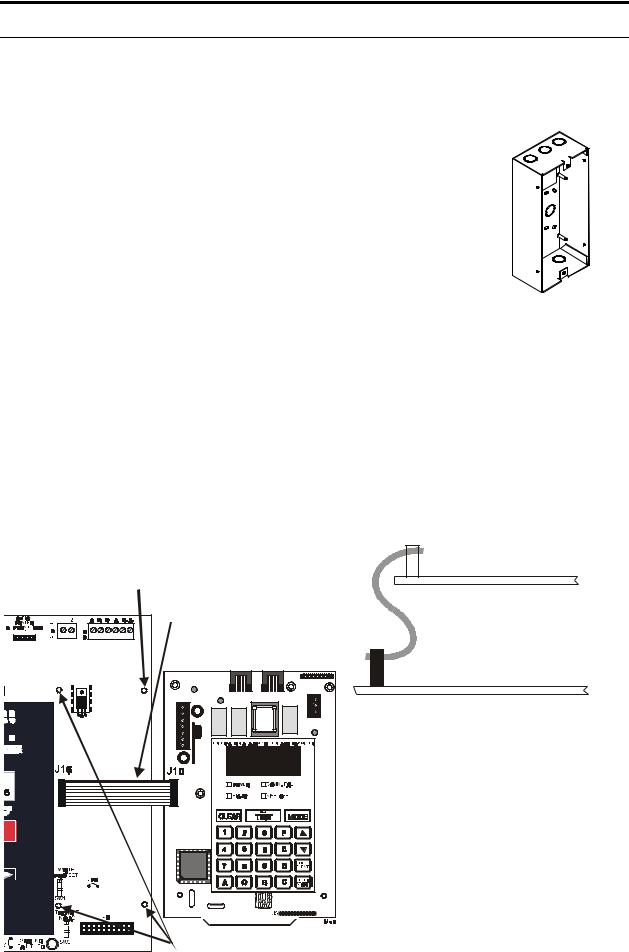
The MS-9200 must have firmware with a Part Number of 73580 or higher installed to allow use of the UDACT-F. Remove all power from the MS-9200 by disconnecting AC and batteries. Install the supplied standoffs (three nylon and one aluminum standoff) in the appropriate holes located on the right side of the MS-9200 main circuit board as illustrated in Figure 2-2. Using the ribbon cable supplied with the UDACT-F, connect J10 on the UDACT-F to J16 on the MS-9200. Note that the colored edge of the ribbon cable must be oriented toward the top edge of the UDACT-F as illustrated in Figure 2-2. Carefully seat the UDACT-F on the nylon standoffs and secure to the aluminum standoff with the supplied screw.
The EIA-485 circuit and 24 VDC power are provided directly from connector J16 of the MS-9200. Note that a 120 ohm EOL resistor is not required on the UDACT-F EIA-485 terminals when it is installed inside the MS-9200 cabinet. The EOL resistor is required at the last device on the EIA-485 line, external to the MS-9200.
FIGURE 2-2:UDACT-F Mounting to MS-9200
Aluminum standoff with nut, required for transient protection
MS-9200 |
Supplied ribbon cable attached as illustrated to the right. Note position of colored edge.
UDACT-F
 J10
J10
UDACT-F
J16
MS-9200
14 |
Nylon standoffs
Document #50049 Rev.E0 1/22/01 P/N 50049:E0

Panel Mounting
FIGURE 2-3:External UDACT-F Mounting in ABS-8RF - MS-9200 Solid Earth
|
|
|
|
|
|
|
Ground |
|
|
|
|
|
|
|
Connection |
Supervised and power-limited EIA-485 and power connections |
DO NOT USE |
||||||
THESE TERMINALS |
|
|
|||||
|
|
|
|||||
|
|
|
|
|
|
|
|
24 VDC |
To Phone |
|
Lines |
||
Nonresettable |
||
(Supervised) |
||
Power |
||
|
||
|
Ferrite Cores |
|
|
P/N FBD-1 |
|
|
Install 120 ohm EOL resistor |
|
|
(P/N 71244) on TB1 Terminals |
|
|
3 & 4, if last or only device on |
|
|
EIA-485 line. |
|
|
MS-9200 cabinet |
|
|
UDACT-F in ABS-8RF |
|
|
(shown with cover removed) |
|
MS-9200 |
|
|
Notes: |
|
1.This arrangement allows use of the UDACT-F simultaneously with the RTM-8F module
2.Ferrite cores are recommended for all applications
3.Recommended wire is 12 AWG to 18 AWG (0.75 to 3.25 mm2) twisted wire
4.Shielded wire is not required (unless mandated by local AHJ) If shield wire is used, connect only one end of the shield:
shield may be connected to cabinet (earth ground) at fire alarm panel, or
shield may be connected to TB1 Terminal 5 (shield) at UDACT-F as shown in Figure 2-3. Note that the shield end that is not connected should be insulated to prevent accidental grounding. Do not connect both ends of the shield under any circumstance, since a ground fault may result.
5.Conduit is recommended for external wire runs. Consult local building codes
6.Connect Ground Strap (supplied with ABS-8RF enclosure) from Earth Ground terminal on the UDACT-F to a solid building earth ground. Conduit alone will not provide a reliable earth ground.
7.UDACT-F may be located up to 6,000 feet (1,800 m) away from the host control panel
8.Refer to “Specifications” on page 10, for power requirements
Document #50049 Rev. E0 01/22/01 P/N 50049:E0 |
15 |

Panel Mounting
CAUTION: Connecting a UDACT-F to an MS-9200 which also has an ACM, AFM or LDM Series annunciator connected, will alter the assignments of the first eight yellow LEDs on the annunciator as follows:
TABLE 2-1: Annunciator LED Assignments (MS-9200)
|
Assignment |
Assignment |
|
Yellow Annunciator LED |
Without UDACT-F |
With UDACT-F |
|
|
|
|
|
1 |
System Trouble |
System Trouble |
|
(less AC loss) |
(less AC loss) |
||
|
|||
|
|
|
|
2 |
Signals Silenced |
Signals Silenced |
|
|
|
|
|
3 |
Not Used |
Program Mode |
|
(panel off-normal) |
|||
|
|
||
|
|
|
|
4 |
Not Used |
Supervisory |
|
|
|
|
|
5 |
Supervisory |
Bell Trouble |
|
|
|
|
|
6 |
Prealarm |
Prealarm/Maintenance Alert |
|
|
|
|
|
7 |
AC Fail |
Low Battery |
|
|
|
|
|
8 |
Panel Trouble |
AC Fail |
|
|
|
|
16 |
Document #50049 Rev.E0 1/22/01 P/N 50049:E0 |
Panel Mounting
2.2.2 MS-9600
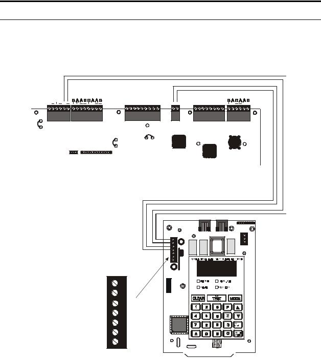
The UDACT-F may be mounted to a BRKT-9600 bracket inside the FACP cabinet (see MS-9600 instruction manual) or mounted remotely in a UBS-1F or ABS-8RF enclosure (see Figure 2-3) and wired according to the diagram below.
FIGURE 2-4:UDACT-F Wiring to MS-9600
24 VDC |
|
|
|
|
|
|
|
|
|
|
Nonresettable |
|
|
|
|
|
T R D G I |
I |
O O |
|
|
Power |
|
|
|
|
|
|
||||
|
|
|
|
|
X C T N N |
N U U |
|
|||
|
|
|
|
|
|
V R D + |
– |
T |
T |
|
|
|
A LA R M |
TR B L |
S UP V |
|
+ – |
|
+ |
– |
shield |
TB3 |
TB4 |
TB5 |
|
|
TB6 |
TB7 |
|
|
|
TB8 |
|
|
|
|
|
|
|||||
JP3 |
|
|
|
|
|
|
|
|
|
|
CUT TO |
|
|
DISABLE |
|
JP5 |
LOCAL |
CUT TO |
|
CHARGER |
JP6 |
|
MONITOR 4XTM |
|
|
|
|
|
|
4XTM OPT BD |
|
|
J10 |
J11 |
MS-9600 Control Panel
+24V |
1 |
GND |
2 |
RS+ |
3 |
RS– |
4 |
SHIELD |
5 |
RS+ |
6 |
RS– |
7 |
J10
J5 
Notes for External Applications:
1.Ferrite cores are recommended for all applications
2.Recommended wire is 12 AWG to 18 AWG (0.75 to 3.25 mm2) twisted wire
3.Shielded wire is not required (unless mandated by local AHJ) If shield wire is used, connect only one end of the shield:
shield may be connected to cabinet (earth ground) at fire alarm panel, or
shield may be connected to TB1 Terminal 5 (shield) at UDACT-F as shown in Figure 2-3. Note that the shield end that is not connected should be insulated to prevent accidental grounding. Do not connect both ends of the shield under any circumstance, since a ground fault may result.
4.Conduit is recommended for external wire runs. Consult local building codes
5.Connect Ground Strap (supplied with ABS-8RF enclosure) from Earth Ground terminal on the UDACT-F to a solid building earth ground. Conduit alone will not provide a reliable earth ground.
6.UDACT-F may be located up to 6,000 feet (1,800 m) away from the host control panel
7.Refer to “Specifications” on page 10, for power requirements
Document #50049 Rev. E0 01/22/01 P/N 50049:E0 |
17 |

Panel Mounting
Connecting a UDACT-F to an MS-9600 which also has an ACM, AFM or LDM Series annunciator connected, will not alter the assignments of the first eight yellow LEDs on the annunciator.
TABLE 2-2: Annunciator LED Assignments (MS-9600)
|
Assignment |
|
Yellow Annunciator LED |
With or Without UDACT-F |
|
|
|
|
1 |
System Trouble |
|
(less AC loss) |
||
|
||
|
|
|
2 |
Signals Silenced |
|
|
|
|
3 |
Program Mode |
|
(panel off-normal) |
||
|
||
|
|
|
4 |
Supervisory |
|
|
|
|
5 |
Bell Trouble |
|
|
|
|
6 |
Prealarm/Maintenance Alert |
|
|
|
|
7 |
Low Battery |
|
|
|
|
8 |
AC Fail |
|
|
|
18 |
Document #50049 Rev.E0 1/22/01 P/N 50049:E0 |

Panel Mounting
2.2.3 Sensiscan 2000
Remove all power from the control panel by disconnecting AC and batteries. Install the three supplied nylon support posts for the top and bottom left of the UDACT-F, one aluminum/nylon and one aluminum standoff in the CHS-4 chassis slot in which the UDACT-F is to be installed (refer to Figure 2-5). Position the UDACT-F on the standoffs and secure on the aluminum standoff with a #6-32 screw. Alternatively, the UDACT-F may be mounted remotely using an ABS-8RF or UBS-1F enclosure. Ferrite cores are recommended for this application. Refer to Figure 2-3, “External UDACT-F Mounting in ABS-8RF - MS-9200,” on page 15, and the accompanying notes for wiring alternatives.
Connect the communication line between the EIA-485 terminal block on the CPU-2000 and TB1 Terminals 3 & 4 on the UDACT-F, making certain to observe polarity. Refer to Figure 2-6, “EIA-485 Connection Sensiscan 2000,” on page 20. Recommended wire is 12 AWG to 18 AWG (0.75 to 3.25 mm2) twisted pair. If no other devices are connected to the EIA-485 line, install a 120 ohm EOL resistor across the UDACT-F TB1 Terminals 3 & 4.
Connect the supplied Ground Strap from the UDACT-F Earth Ground terminal on TB3 to the CHS-4 chassis. Connect 24 VDC filtered, nonresettable power to TB1 Terminals 1 & 2 on the UDACT-F. Refer to Figure 2-7, “24 VDC Power Connection to UDACT-F,” on page 21.
FIGURE 2-5:UDACT-F Mounting in CHS-4
UDACT-F
nylon support posts
ground strap
CPU-2000
CHS-4
nylon & aluminum standoff
aluminum standoff and screw
Document #50049 Rev. E0 01/22/01 P/N 50049:E0 |
19 |

Panel Mounting
FIGURE 2-6:EIA-485 Connection Sensiscan 2000
 EIA-485 (supervised and power-limited)
-
+
TB1
Terminal 3 RS+
Terminal 4 RS-
+
-
Install 120 ohm EOL resistor (P/N: 71244) across Terminals 3 (RS+) & 4 (RS-) if last or only device on EIA-485 line. Note that Terminals 6 (RS+) & 7 (RS-) are not used at this time.
CPU-2000
UDACT-F
20 |
Document #50049 Rev.E0 1/22/01 P/N 50049:E0 |
Panel Mounting
FIGURE 2-7:24 VDC Power Connection to UDACT-F
Power (supervised and power-limited)
TB1-1 +
TB1-2 -
|
|
|
|
|
|
|
|
|
|
|
|
|
|
|
|
|
|
|
|
|
|
|
|
|
|
|
|
|
|
|
|
|
|
TB3-3 + |
|
|
|
|
|
- TB3-4 |
|
|
|
|
|||||||||||||||||||
|
|
|
|
|
|
|
|
|
|
|
|
|
|
|
|
|
|
|
|
|
|
|
|
|
|
|
|
|
|
|
|
|
|
|
|
|
|
|
|
|
|
|
|||||||||||||||||||||
|
|
|
|
|
|
|
|
|
|
|
|
|
|
|
|
|
|
|
|
|
|
|
|
|
|
|
|
|
|
|
|
|
|
|
|
|
|
|
|
|
|
|
|
|
|
|
|
|
|
|
|
|
|
|
|
|
|
|
|
|
|
|
|
|
|
|
|
|
|
|
|
|
|
|
|
|
|
|
|
|
|
|
|
|
|
|
|
|
|
|
|
|
|
|
|
|
|
|
|
|
|
|
|
|
|
|
|
|
|
|
|
|
|
|
|
|
|
|
|
|
|
|
|
|
|
|
|
|
|
|
|
|
|
|
|
|
|
|
|
|
|
|
|
|
|
|
|
|
|
|
|
|
|
|
|
|
|
|
|
|
|
|
|
|
|
|
|
|
|
|
|
|
|
|
|
|
|
|
|
|
|
|
|
|
|
|
|
|
|
|
|
|
|
|
|
|
|
|
|
|
|
|
|
|
|
|
|
|
|
|
|
|
|
|
|
|
|
|
|
|
|
|
|
|
|
|
|
|
|
|
|
|
|
|
|
|
|
|
|
|
|
|
|
|
|
|
|
|
|
|
|
|
|
|
|
|
|
|
|
|
|
|
|
|
|
|
|
|
|
|
|
|
|
|
|
|
|
|
|
|
|
|
|
|
|
|
|
|
|
|
|
|
|
|
|
|
|
|
|
|
|
|
|
|
|
|
|
|
|
|
|
|
|
|
|
|
|
|
|
|
|
|
|
|
|
|
|
|
|
|
|
|
|
|
|
|
|
|
|
|
|
|
|
|
|
|
|
|
|
|
|
|
|
|
|
|
|
|
|
|
|
|
|
|
|
|
|
|
|
|
|
|
|
|
|
|
|
|
|
|
|
|
|
|
|
|
|
|
|
|
|
|
|
|
|
|
|
|
|
|
|
|
|
|
|
|
|
|
|
|
|
|
|
|
|
|
|
|
|
|
|
|
|
|
|
|
|
|
|
|
|
|
|
|
|
|
|
|
|
|
|
|
|
|
|
|
|
|
|
|
|
|
|
|
|
|
|
|
|
|
|
|
|
|
|
|
|
|
|
|
|
|
|
|
|
|
|
|
|
|
|
|
|
|
|
|
|
|
|
|
|
|
|
|
|
|
|
|
|
|
|
|
|
|
|
|
|
|
|
|
|
|
|
|
|
|
|
|
|
|
|
|
|
|
|
|
|
|
|
|
|
|
|
|
|
|
|
|
|
|
|
|
|
|
|
|
|
|
|
|
|
|
|
|
|
|
|
|
|
|
|
|
|
|
|
|
|
|
|
|
|
|
|
|
|
|
|
|
|
|
|
|
|
|
|
|
|
|
|
|
|
|
|
|
|
|
|
|
|
|
|
|
|
|
|
|
|
|
|
|
|
|
|
|
|
|
|
|
|
|
|
|
|
|
|
|
|
|
|
|
|
|
|
|
|
|
|
|
|
|
|
|
|
|
|
|
|
|
|
|
|
|
|
|
|
|
|
|
|
|
|
|
|
|
|
|
|
|
|
|
|
|
|
|
|
|
|
|
|
|
|
|
|
|
|
|
|
|
|
|
|
|
|
|
|
|
|
|
|
|
|
|
|
|
|
|
|
|
|
|
|
|
|
|
|
|
|
|
|
|
|
|
|
|
|
|
|
|
|
|
|
|
|
|
|
|
|
|
|
|
|
|
|
|
|
|
|
|
|
|
|
|
|
|
|
|
|
|
|
|
|
|
|
|
|
|
|
|
|
|
|
|
|
|
|
|
|
|
|
|
|
|
|
|
|
|
|
|
|
|
|
|
|
|
|
|
|
|
|
|
|
|
|
|
|
|
|
|
|
|
|
|
|
|
|
|
|
|
|
|
|
|
|
|
|
|
|
|
|
|
|
|
|
|
|
|
|
|
|
|
|
|
|
|
|
|
|
|
|
|
|
|
|
|
|
|
|
|
|
|
|
|
|
|
|
|
|
|
|
|
|
|
|
|
|
|
|
|
|
|
|
|
|
|
|
|
|
|
|
|
|
|
|
|
|
|
|
|
|
|
|
|
|
|
|
|
|
|
|
|
|
|
|
|
|
|
|
|
|
|
|
|
|
|
|
|
|
|
|
|
|
|
|
|
|
|
|
|
|
|
|
|
|
|
|
|
|
|
|
|
|
|
|
|
|
|
|
|
|
|
|
|
|
|
|
|
|
|
|
|
|
|
|
|
|
|
|
|
|
|
|
|
|
|
|
|
|
|
|
|
|
|
|
|
|
|
|
|
|
|
|
|
|
|
|
|
|
|
|
|
|
|
|
|
|
|
|
|
|
|
|
|
|
|
|
|
|
|
|
|
|
|
|
|
|
|
|
|
|
|
|
|
|
|
|
|
|
|
|
|
|
|
|
|
|
|
|
|
|
|
|
|
|
|
|
|
|
|
|
|
|
|
|
|
|
|
|
|
|
|
|
|
|
|
|
|
|
|
|
|
|
|
|
|
|
|
|
|
|
|
|
|
|
|
|
|
|
|
|
|
|
|
|
|
|
|
|
|
|
|
|
|
|
|
|
|
|
|
|
|
|
|
|
|
|
|
|
|
|
|
|
|
|
|
|
|
|
|
|
|
|
|
|
|
|
|
|
|
|
|
|
|
|
|
|
|
|
|
|
|
|
|
|
|
|
|
|
|
|
|
|
|
|
|
|
|
|
|
|
|
|
|
|
|
|
|
|
|
|
|
|
|
|
|
|
|
|
|
|
|
|
|
|
|
|
|
|
|
|
|
|
|
|
|
|
|
|
|
|
|
|
|
|
|
|
|
|
|
|
|
|
|
|
|
|
|
|
|
|
|
|
|
|
|
|
|
|
|
|
|
|
|
|
|
|
|
|
|
|
|
|
|
|
|
|
|
|
|
|
|
|
|
|
|
|
|
|
|
|
|
|
|
|
|
|
|
|
|
|
|
|
|
|
|
|
|
|
|
|
|
|
|
|
|
|
|
|
|
|
|
|
|
|
|
|
|
|
|
|
|
|
|
|
|
|
|
|
|
|
|
|
|
|
|
|
|
|
|
|
|
|
|
|
|
|
|
|
|
|
|
|
|
|
|
|
|
|
|
|
|
|
|
|
|
|
|
|
|
|
|
|
|
|
|
|
|
|
|
|
|
|
|
|
|
|
|
|
|
|
|
|
|
|
|
|
|
|
|
|
|
|
|
|
|
|
|
|
|
|
|
|
|
|
|
|
|
|
|
|
|
|
|
|
|
|
|
|
|
|
|
|
|
|
|
|
|
|
|
|
|
|
|
|
|
|
|
|
|
|
|
|
|
|
|
|
|
|
|
|
|
|
|
|
|
|
|
|
|
|
|
|
|
|
|
|
|
|
|
|
|
|
|
|
|
|
|
|
|
|
|
|
|
|
|
|
|
|
|
|
|
|
|
|
|
|
|
|
|
|
|
|
|
|
|
|
|
|
|
|
|
|
|
|
|
|
|
|
|
|
|
|
|
|
|
|
|
|
|
|
|
|
|
|
|
|
|
|
|
|
|
|
|
|
|
|
|
|
|
|
|
|
|
|
|
|
|
|
|
|
|
|
|
|
|
|
|
|
|
|
|
|
|
|
|
|
|
|
|
|
|
|
|
|
|
|
|
|
|
|
|
|
|
|
|
|
|
|
|
|
|
|
|
|
|
|
|
|
|
|
|
|
|
|
|
|
|
|
|
|
|
|
|
|
|
|
|
|
|
|
|
|
|
|
|
|
|
|
|
|
|
|
|
|
|
|
|
|
|
|
|
|
|
|
|
|
|
|
|
|
|
|
|
|
|
|
|
|
|
|
|
|
|
|
|
|
|
|
|
|
|
|
|
|
|
|
|
|
|
|
|
|
|
|
|
|
|
|
|
|
|
|
|
|
|
|
|
|
|
|
|
|
|
|
|
|
|
|
|
|
|
|
|
|
|
|
|
|
|
|
|
|
|
|
|
|
|
|
|
|
|
|
|
|
|
|
|
|
|
|
|
|
|
|
|
|
|
|
|
|
|
|
|
|
|
|
|
|
|
|
|
|
UDACT-F
MPS-24AF
Power (supervised and power-limited) |
TB1-1 + |
TB1-2 -
TB2-1 + - TB2-2


 Cut jumper JP1 to make output nonresettable for use with UDACT-F
UDACT-F |
MPS-24BF |
Note: Power for the UDACT-F must be 24 VDC filtered, nonresettable
Document #50049 Rev. E0 01/22/01 P/N 50049:E0 |
21 |
 Loading...