


MS-9050UD

Addressable Fire Alarm Control Panel
MS-9050UD
PN: 52413:B ECN 07-494
IMPORTANT! The SLC Manual Document #51309 must be referenced in addition to this
manual when installing or servicing the Fire Alarm Control Panel.
Document #52413
8/29/07 Revision:
B

PrecauLarge.PMD 02/26/2007
An automatic fire alarm system–typically made up of
smoke detectors, heat detectors, manual pull stations,
audible warning devices, and a fire alarm control panel with
remote notification capability–can provide early warning of a
developing fire. Such a system, however, does not assure
protection against property damage or loss of life resulting
from a fire.
The Manufacturer recommends that smoke and/or heat
detectors be located throughout a protected premise follow-
ing the recommendations of the current edition of the
National Fire Protection Association Standard 72 (NFPA 72),
manufacturer's recommendations, State and local codes,
and the recommendations contained in the Guides for
Proper Use of System Smoke Detectors, which are made
available at no charge to all installing dealers. These docu-
ments can be found at http:/www.systemsensor.com/html/
applicat.html. A study by the Federal Emergency Manage-
ment Agency (an agency of the United States government)
indicated that smoke detectors may not go off in as many as
35% of all fires. While fire alarm
systems are designed to provide early warning against fire,
they do not guarantee warning or protection against fire. A
fire alarm system may not provide timely or adequate
warning, or simply may not function, for a variety of reasons:
Smoke detectors may not sense fire where smoke cannot
reach the detectors such as in chimneys, in or behind walls,
on roofs, or on the other side of closed doors. Smoke
detectors also may not sense a fire on another level or floor
of a building. A second-floor detector, for example, may not
sense a first-floor or basement fire.
Particles of combustion or "smoke" from a developing fire
may not reach the sensing chambers of smoke detectors
because:
• Barriers such as closed or partially closed doors, walls, or
chimneys may inhibit particle or smoke flow.
• Smoke particles may become "cold," stratify, and not
reach the ceiling or upper walls where detectors are
located.
• Smoke particles may be blown away from detectors by air
outlets.
• Smoke particles may be drawn into air returns before
reaching the detector.
The amount of "smoke" present may be insufficient to alarm
smoke detectors. Smoke detectors are designed to alarm
at various levels of smoke density. If such density levels are
not created by a developing fire at the location of detectors,
the detectors will not go into alarm.
Smoke detectors, even when working properly, have sens-
ing limitations. Detectors that have photoelectronic sensing
chambers tend to detect smoldering fires better than flam-
ing fires, which have little visible smoke. Detectors that have
ionizing-type sensing chambers tend to detect fast-flaming
fires better than smoldering fires. Because fires develop in
different ways and are often unpredictable in their growth,
neither type of detector is necessarily best and a given type
of detector may not provide adequate warning of a fire.
Smoke detectors cannot be expected to provide adequate
warning of fires caused by arson, children playing with
matches (especially in bedrooms), smoking in bed, and
violent explosions (caused by escaping gas, improper stor-
age of flammable materials, etc.).
Heat detectors do not sense particles of combustion and
alarm only when heat on their sensors increases at a
predetermined rate or reaches a predetermined level.
Rate-of-rise heat detectors may be subject to reduced
sensitivity over time. For this reason, the rate-of-rise
feature of each detector should be tested at least once
per year by a qualified fire protection specialist. Heat
detectors are designed to protect property, not life.
IMPORTANT! Smoke detectors must be installed in the
same room as the control panel and in rooms used by
the system for the connection of alarm transmission
wiring, communications, signaling, and/or power. If
detectors are not so located, a developing fire may
damage the alarm system, crippling its ability to report
a fire.
Audible warning devices such as bells may not alert
people if these devices are located on the other side of
closed or partly open doors or are located on another
floor of a building. Any warning device may fail to alert
people with a disability or those who have recently con-
sumed drugs, alcohol or medication. Please note that:
• Strobes can, under certain circumstances, cause
seizures in people with conditions such as epilepsy.
• Studies have shown that certain people, even when
they hear a fire alarm signal, do not respond or com-
prehend the meaning of the signal. It is the property
owner's responsibility to conduct fire drills and other
training exercise to make people aware of fire alarm
signals and instruct them on the proper reaction to
alarm signals.
• In rare instances, the sounding of a warning device
can cause temporary or permanent hearing loss.
A fire alarm system will not operate without any
electrical power. If AC power fails, the system will
operate from standby batteries only for a specified time
and only if the batteries have been properly maintained
and replaced regularly.
Equipment used in the system may not be technically
compatible with the control. It is essential to use only
equipment listed for service with your control panel.
Telephone lines needed to transmit alarm signals from
a premise to a central monitoring station may be out of
service or temporarily disabled. For added protection
against telephone line failure, backup radio transmis-
sion systems are recommended.
The most common cause of fire alarm malfunction is
inadequate maintenance. To keep the entire fire alarm
system in excellent working order, ongoing maintenance
is required per the manufacturer's recommendations,
and UL and NFPA standards. At a minimum, the require-
ments of NFPA 72 shall be followed. Environments with
large amounts of dust, dirt or high air velocity require
more frequent maintenance. A maintenance agreement
should be arranged through the local manufacturer's
representative. Maintenance should be scheduled
monthly or as required by National and/or local fire codes
and should be performed by authorized professional fire
alarm installers only. Adequate written records of all
inspections should be kept.
While a fire alarm system may lower insurance
rates, it is not a substitute for fire insurance!
Fire Alarm System Limitations

PrecauLarge.PMD 02/26/2007
WARNING - Several different sources of power can be
connected to the fire alarm control panel. Disconnect all
sources of power before servicing. Control unit and asso-
ciated equipment may be damaged by removing and/or
inserting cards, modules, or interconnecting cables while
the unit is energized. Do not attempt to install, service, or
operate this unit until this manual is read and understood.
CAUTION - System Reacceptance Test after Software
Changes. To ensure proper system operation, this product
must be tested in accordance with NFPA 72 after any
programming operation or change in site-specific software.
Reacceptance testing is required after any change,
addition or deletion of system components, or after any
modification, repair or adjustment to system hardware or
wiring.
All components, circuits, system operations, or software
functions known to be affected by a change must be 100%
tested. In addition, to ensure that other operations are not
inadvertently affected, at least 10% of initiating devices that
are not directly affected by the change, up to a maximum of
50 devices, must also be tested and proper system
operation verified.
This system meets NFPA requirements for indoor dry
operation at 0-49° C/32-120° F
and at a relative humidity of
93 ±2% RH (non-condensing) at 32 ±2°
C/90 ±3° F.
However, the useful life of the system's standby batteries
and the electronic components may be adversely affected
by extreme temperature ranges and humidity. Therefore, it
is recommended that this system and all peripherals be
installed in an environment with a nominal room tempera-
ture of 15-27° C/60-80° F.
Verify that wire sizes are adequate for all initiating and
indicating device loops. Refer to manual Specifications
section for maximum allowable I.R. drop from the specified
device voltage.
Like all solid state electronic devices, this system may
operate erratically or can be damaged when subjected to
lightning-induced transients. Although no system is
completely immune from lightning transients and
interferences, proper grounding will reduce susceptibility.
Overhead or outside aerial wiring is not recommended, due
to an increased susceptibility to nearby lightning strikes.
Consult with the Technical Services Department if any
problems are anticipated or encountered.
Disconnect AC power and batteries prior to removing or
inserting circuit boards. Failure to do so can damage
circuits.
Remove all electronic assemblies prior to any drilling,
filing, reaming, or punching of the enclosure. When
possible, make all cable entries from the sides or rear.
Before making modifications, verify that they will not
interfere with battery, transformer, and printed circuit board
location.
Do not tighten screw terminals more than 9 in-lbs.
Over-tightening may damage threads, resulting in reduced
terminal contact pressure and difficulty with screw terminal
removal.
This system contains static-sensitive components.
Always ground yourself with a proper wrist strap before
handling any circuits so that static charges are removed
from the body. Use static-suppressive packaging to
protect electronic assemblies removed from the unit.
Follow the instructions in the installation, operating, and
programming manuals. These instructions must be
followed to avoid damage to the control panel and
associated equipment. FACP operation and reliability
depend upon proper installation by authorized personnel.
Adherence to the following will aid in problem-free
installation with long-term reliability:
WARNING: This equipment generates, uses, and can
radiate radio frequency energy and if not installed and
used in accordance with the instruction manual, may
cause interference to radio communications. It has
been tested and found to comply with the limits for class
A computing device pursuant to Subpart B of Part 15 of
FCC Rules, which is designed to provide reasonable
protection against such interference when operated in a
commercial environment. Operation of this equipment
in a residential area is likely to cause interference, in
which case the user will be required to correct the
interference at their own expense.
Canadian Requirements
This digital apparatus does not exceed the Class A
limits for radiation noise emissions from digital
apparatus set out in the Radio Interference Regulations
of the Canadian Department of Communications.
Le present appareil numerique n'emet pas de bruits
radioelectriques depassant les limites applicables aux
appareils numeriques de la classe A prescrites dans le
Reglement sur le brouillage radioelectrique edicte par
le ministere des Communications du Canada.
FCC Warning
Installation Precautions

Table of Contents
4
MS-9050UD P/N: 52413:B 8/29/07
SECTION 1: Product Description .........................................................................................................................12
1.1: Features and Options...................................................................................................................................12
1.2: Specifications ..............................................................................................................................................13
1.2.1: Current Availability...........................................................................................................................14
1.3: Controls and Indicators........................................................................................... .....................................14
1.4: Circuits ........................................................................................................................................................15
1.5: Digital Alarm Communicator/Transmitter..................................................................................................16
1.6: Components.................................................................................................................................................17
1.6.1: Intelligent Addressable Detectors: Newer Series..............................................................................17
1.6.2: Intelligent Addressable Modules: Newer Series............................................................. ..................17
1.6.3: 300 Series Intelligent Addressable Devices......................................................................................17
1.6.4: Device Accessories ...........................................................................................................................17
1.7: Optional Modules........................................................................................................................................18
1.8: Accessories..................................................................................................................................................18
1.8.1: PK-CD Programming Utility ............................................................................................................18
1.8.2: Dress Panel........................................................................................................................................18
1.8.3: Trim Ring..........................................................................................................................................18
1.9: ANN-BUS Devices .....................................................................................................................................19
1.9.1: ANN-BUS Wiring.............................................................................................................................19
1.9.1.1 Calculating Wiring Distance for ANN-BUS Modules ............................................................ 19
1.9.1.2 Wiring Configuration ..............................................................................................................21
1.9.1.3 Powering ANN-BUS Devices from Auxiliary Power Supply ................................................22
1.9.2: ANN-BUS Device Addressing..........................................................................................................22
1.9.3: ANN-80 Remote Fire Annunciator...................................................................................................23
1.9.3.1 Specifications ....................................................................................... ...................................23
1.9.3.2 Installation ................................................................................. ..............................................23
1.9.3.3 Mounting .......................................................................................................... .......................23
1.9.3.4 Opening/Closing Annunciator .......................................................................................... ......23
1.9.3.5 Wiring ANN-80 to FACP ................................................................................... ....................24
1.9.4: ANN-S/PG Serial/Parallel Interface Module....................................................................................26
1.9.4.1 Specifications ....................................................................................... ...................................26
1.9.4.2 PRN 6 Printer Installation .......................................................................................................26
1.9.4.2.1 Connecting PRN 6 Printer ....................................................................................................27
1.9.4.2.2 Setting Printer Options .........................................................................................................27
1.9.5: ANN-I/O LED Driver Module..........................................................................................................28
1.9.5.1 ANN-I/O Board Layout ................................................................................ ..........................28
1.9.5.2 Specifications ....................................................................................... ...................................28
1.9.5.3 ANN-I/O Connection to FACP ...............................................................................................29
1.9.5.4 ANN-I/O Module LED Wiring ...............................................................................................30
1.9.6: ANN-LED Annunciator Module.......................................................................................................31
1.9.6.1 ANN-LED Board Layout ........................................................................................................31
1.9.6.2 Specifications ....................................................................................... ...................................31
1.9.6.3 ANN-LED Connection to FACP ............................................................................................32
1.9.7: ANN-RLY Relay Module..................................................................................................................33
1.9.7.1 ANN-RLY Board Layout ........................................................................................................33
1.9.7.2 Specifications ....................................................................................... ...................................33
1.9.7.3 Mounting/Installation .......................................... ..................................................... ............... 33
1.9.7.4 ANN-RLY Connection to FACP ............................................................................................34
1.10: Getting Started...........................................................................................................................................34
1.11: Telephone Requirements and Warnings....................................................................................................35
1.11.1: Telephone Circuitry.........................................................................................................................35
1.11.2: Digital Communicator.....................................................................................................................35
1.11.3: Telephone Company Rights and Warnings .....................................................................................36
1.11.4: For Canadian Applications..............................................................................................................37
SECTION 2: Installation ........................................................................................................................................38
Table of Content s

MS-9050UD P/N: 52413:B 8/29/07 5
Table of Contents
2.1: Mounting Backbox............................................... ...................................................... ................................. 38
2.2: Mounting Chassis/Transformer/Main Circuit Board...................................................................................39
2.3: Power...........................................................................................................................................................42
2.3.1: AC Power and Earth Ground Connection.........................................................................................42
2.3.2: Battery Power....................................................................................................................................42
2.4: Relays.............................................................................................................. ............................................43
2.5: Notification Appliance Circuits ..................................................................................................................43
2.5.1: Configuring NACs........................................................................................... .................................44
2.6: UL Power-limited Wiring Requirements....................................................................................................45
2.7: Digital Communicator.................................................................................................................................46
2.8: Optional Modules/Accessories Installation.................................................................................................47
2.8.1: 4XTMF Transmitter Module Installation..........................................................................................47
SECTION 3: Programming ..................................................................................................... ..............................50
3.1: Programming Data Entry ............................................................................................................................50
3.2: User Programming ............................ ..................................................... .....................................................51
3.3: Initial Power-up...................................................................................... .....................................................52
3.4: Programming Screens Description..............................................................................................................52
3.5: Programming and Passwords ......................................................................................................................52
3.6: Master Programming Level............................................................ .............................................................54
3.6.1: Autoprogram......................................... ..................................................... .......................................55
3.6.2: Point Program........................................................................................ ............................................56
3.6.2.1 Detector Programming ............................................................................................................56
3.6.2.1.1 Add Detector ........................................................................................................................56
3.6.2.1.2 Delete Detector ....................................................................................................................57
3.6.2.1.3 Edit Detector ........................................................................................................................57
3.6.2.2 Module Programming .............................................................................................................66
3.6.2.2.1 Add Module .........................................................................................................................66
3.6.2.2.2 Delete Module ......................................................................................................................67
3.6.2.2.3 Edit Module Screen for Monitor Module ............................................................................67
3.6.2.2.4 Edit Module Screen for Control Modules ............................................................................76
3.6.3: Zone Setup ........................................................................................................................................83
3.6.3.1 Enable ......................................................................................................................................83
3.6.3.2 Disable ....................................................................................................................................84
3.6.3.3 Zone 17, 18 and 19 ..................................................................................................................84
3.6.3.4 Zones Installed ........................................................................................................................85
3.6.3.5 Zones Enabled .........................................................................................................................85
3.6.3.6 Zones Disabled ........................................................................................................................85
3.6.3.7 Zone Type ...............................................................................................................................85
3.6.3.8 Zones Available ......................................................................................................................87
3.6.4: Loop Setup...................................... ...................................................... ............................................87
3.6.4.1 Style ........................................................................................................................................87
3.6.4.2 Loop Protocol .........................................................................................................
.................87
3.6.5: System Setup................................ ...................................................... ...............................................88
3.6.5.1 Trouble Reminder ...................................................................................................................89
3.6.5.2 Banner .....................................................................................................................................89
3.6.5.3 Time-Date ...............................................................................................................................90
3.6.5.3.1 Time .....................................................................................................................................90
3.6.5.3.2 Date ......................................................................................................................................91
3.6.5.3.3 Clock Format ........................................................................................................................91
3.6.5.3.4 Daylight Savings Time .........................................................................................................91
3.6.5.4 Timers .....................................................................................................................................92
3.6.5.4.1 PAS (Positive Alarm Sequence) Delay ................................................................................92
3.6.5.4.2 Pre-signal Delay ...................................................................................................................93
3.6.5.4.3 Waterflow Delay ..................................................................................................................93
3.6.5.4.4 AC Loss Delay .....................................................................................................................94

Table of Contents
6
MS-9050UD P/N: 52413:B 8/29/07
3.6.5.5 NAC (Notification Appliance Circuit) ....................................................................................94
3.6.5.5.1 Enabled ....................................................................................................... ..........................95
3.6.5.5.2 Type ........................................................................................ ..............................................96
3.6.5.5.3 Silenceable ...........................................................................................................................96
3.6.5.5.4 Auto Silence .........................................................................................................................97
3.6.5.5.5 Coding (only for NACs not programmed as Sync Strobe Type) .........................................97
3.6.5.5.6 Zone ........................................................................................ ..............................................99
3.6.5.5.7 Silence Inhibited ......................................................................................... ..........................99
3.6.5.5.8 Sync Type ..................................... ........................................................................................99
3.6.5.6 Relays .............................................................................................. ........................................100
3.6.5.7 Canadian Option ............................................................................................ ..........................101
3.6.5.8 Waterflow Silenceable ............................................................................................................101
3.6.6: Verify Loop .......................................................................................................................................101
3.6.7: History...............................................................................................................................................102
3.6.7.1 View Events ........................................................................................................ ....................102
3.6.7.2 Erase History ........................................................................................... ................................102
3.6.8: Walktest.............................................................................................................................................103
3.6.9: Option Modules................................................................................................................................104
3.6.9.1 ANN-BUS ........................................................................................................... ....................104
3.6.9.1.1 ANN-BUS Enabled ............................................................................................ ..................104
3.6.9.1.2 Modules Installed .................................................. ...............................................................105
3.6.9.1.3 Auto-Configure .................................................................................................. .................. 115
3.6.9.1.4 ANN-S/PG (Print) Options Screen ......................................................................................115
3.6.9.1.5 ANN-80 Options Screen ......................................................................................................116
3.6.9.2 Onboard DACT ............................................................................................. ..........................117
3.6.9.2.1 Onboard DACT Enable ........................................................................................................117
3.6.9.2.2 Primary Phone ............................................................................................... .......................117
3.6.9.2.3 Secondary Phone ................................................................................................ ..................118
3.6.9.2.4 Service Terminal ........................................................................................ ..........................118
3.6.9.2.5 Central Station ......................................................................................................................121
3.6.9.2.6 Trouble Call Limit (Dialer Runaway Prevention) ...............................................................122
3.6.9.2.7 Manual Dial Mode ...............................................................................................................134
3.6.10: Password Change ............................................................................................................................135
3.6.11: Clear Program..................................................................................................................................136
3.6.12: Program Check................................................................................................................................137
3.7: Maintenance Programming Level ...............................................................................................................139
3.7.1: Disable Point.....................................................................................................................................140
3.7.2: History...............................................................................................................................................141
3.7.3: Program Check..................................................................................................................................142
3.7.4: Walktest.............................................................................................................................................143
3.7.5: System...............................................................................................................................................143
3.7.6: Zone Setup.........................................................................................................................................145
SECTION 4: Operating Instructions ....................................................................................................................147
4.1: Panel Control Buttons..................................................................................................................................147
4.1.1: Acknowledge/Step.............................................................................................................................147
4.1.2: Alarm Silence....................................................................................................................................147
4.1.3: Drill/Hold 2 Sec ................................................................................................................................147
4.1.4: Reset..................................................................................................................................................147
4.2: Status Indicators and LEDs.........................................................................................................................148
4.3: Normal Operation........................................................................................................................................149
4.4: Trouble Operation........................................................................................................................................149
4.5: Alarm Operation..........................................................................................................................................151
4.6: Supervisory Operation.................................................................................................................................152
4.7: Process Monitor Operation..........................................................................................................................153
4.8: Hazard/Tornado Condition Operation .........................................................................................................153

MS-9050UD P/N: 52413:B 8/29/07 7
Table of Contents
4.9: Medical Alert Condition Operation.............................................................................................................153
4.10: NAC Operation .........................................................................................................................................153
4.11: Programmed Zone Operation....................................................................................................................154
4.12: Disable/Enable Operation .........................................................................................................................154
4.13: Waterflow Circuits Operation ...................................................................................................................154
4.14: Detector Functions ....................................................................................................................................154
4.15: Time Functions: Real-Time Clock ............................................................................................................154
4.16: Synchronized NAC Operation ..................................................................................................................155
4.17: Coded Operation .......................................................................................................................................155
4.18: Presignal....................................................................................................................................................155
4.19: Positive Alarm Sequence ..........................................................................................................................156
4.20: Special System Timers..............................................................................................................................157
4.20.1: Silence Inhibit Timer.......................................................................................................................157
4.20.2: Autosilence Timer............................ ..................................................... ..........................................157
4.20.3: Trouble Reminder ....................................................................................................... ....................157
4.20.4: Waterflow Retard Timer..................................................................................................................157
4.20.5: Alarm Verification (None or One Minute)......................................................................................158
4.21: Walktest.....................................................................................................................................................158
4.22: Read Status................................................................................................................................................159
4.22.1: System Point ....................................... ............................................................................................160
4.22.2: Zones.......................................... ...................................................... ...............................................161
4.22.3: Power............................ ...................................................... .............................................................162
4.22.4: Trouble Reminder ....................................................................................................... ....................163
4.22.5: Timers............. ...................................................... ...........................................................................163
4.22.6: NAC ................................................................................................................................................164
4.22.7: Relays.............................. ...................................................... ..........................................................164
4.22.8: Program Check................................................................................................................................165
4.22.9: History......................................................................................................... ....................................165
4.22.10: ANN-BUS.....................................................................................................................................166
4.22.11: Phone Line.....................................................................................................................................167
4.22.12: Central Station...............................................................................................................................167
4.22.13: Service Terminal ...........................................................................................................................168
4.22.14: Print...............................................................................................................................................169
4.22.15: Time-Date......................................................................................................................................171
SECTION 5: Central Station Communications ..................................................................................................172
5.1: Transmittal Priorities.................................... ..................................................... ..........................................175
SECTION 6: Local/Remote Site Upload/Download ............................................................................................177
6.1: Remote Download.................................. ...................................................... ...............................................177
6.2: Transferring a Program........................... .....................................................................................................178
6.3: Security Features.........................................................................................................................................179
SECTION 7: Power Supply Calculations .............................................................................................................180
7.1: Overview..................................... ...................................................... ..........................................................180
7.2: Calculating the AC Branch Circuit .............................................................................................................180
7.3: Calculating the System Current Draw............................................................. ............................................181
7.3.1: Overview............................................... ..................................................... .......................................181
7.3.2: How to Use Table 7.3 on page 182 to Calculate System Current Draw ...........................................181
7.4: Calculating the Battery Size..............................................................................................
..........................183
7.4.1: NFPA Battery Requirements................................................ .............................................................183
7.4.2: Selecting and Locating Batteries.......................................................................................................183
APPENDIX A: Software Zones ............................................................................................................................184
A.1: Correlations ...............................................................................................................................................184
APPENDIX B: Default Programming .................................................................................................................189
APPENDIX C: NFPA Standard-Specific Requirements ...................................................................................190

Table of Contents
8
MS-9050UD P/N: 52413:B 8/29/07
C.1: Central Station/Remote Station Transmitter:
Connection to FACP Dry Contacts ...........................................................................................................194
C.2: MBT-1 Municipal Box Trip - Silenceable .................................................................................................195
APPENDIX D: FACP with Keltron .....................................................................................................................196
APPENDIX E: Wire Requirements .................................................................................. ...................................197
APPENDIX F: HVAC Control ........................................................................................ .....................................198
F.1: Control Module Operation .........................................................................................................................198
F.1.1: HVAC SHUTDN .............................................................................................................................198
F.2: Monitor Module Operation ........................................................................................................................198
F.2.1: HVAC RESTART ............................................................................................................................198
F.2.2: HVAC OVRRIDE ............................................................................................................................199
APPENDIX G: Ademco Contact ID Format
Event Code Descriptions ...............................................................................................................200
G.1: Transmission Format Between DACT and Receiver ................................................................................200
G.2: Ademco Contact ID Typical Printout ........................................................................................................200

MS-9050UD PN 52413:B 8/29/07 9
It is imperative that the installer understand the requirements of the Authority Having Jurisdiction
(AHJ) and be familiar with the standards set forth by the following regulatory agencies:
• Underwriters Laboratories Standards
• NFPA 72 National Fire Alarm Code
• CAN/ULC - S527-99 Standard for Control Units for Fire Alarm Systems
NFPA Standards
NFPA 72 National Fire Alarm Code
NFPA 70 National Electrical Code
Underwriters Laboratories Documents:
UL 38 Manually Actuated Signaling Boxes
UL 217 Smoke Detectors, Single and Multiple Station
UL 228 Door Closers–Holders for Fire Protective Signaling Systems
UL 268 Smoke Detectors for Fire Protective Signaling Systems
UL 268A Smoke Detectors for Duct Applications
UL 346 Waterflow Indicators for Fire Protective Signaling Systems
UL 464 Audible Signaling Appliances
UL 521 Heat Detectors for Fire Protective Signaling Systems
UL 864 Standard for Control Units for Fire Protective Signaling Systems
UL 1481 Power Supplies for Fire Protective Signaling Systems
UL 1610 Central Station Burglar Alarm Units
UL 1638 Visual Signaling Appliances
UL 1971 Signaling Devices for Hearing Impaired
UL 2017 General-Purpose Signaling Devices and System
CAN/ULC - S524-01 Standard for Installation of Fire Alarm Systems
Other:
EIA-232E Serial Interface Standard
EIA-485 Serial Interface Standard
NEC Article 250 Grounding
NEC Article 300 Wiring Methods
NEC Article 760 Fire Protective Signaling Systems
Applicable Local and State Building Codes
Requirements of the Local Authority Having Jurisdiction (LAHJ)
Fire-Lite Documents:
Fire-Lite Device Compatibility Document #15384
SLC Wiring Manual Document #51309
This product has been certified to comply with the requirements in the Standard for Control Units and Accessories for Fire
Alarm Systems, UL 864, 9th Edition. Operation of this product with products not tested for UL 864, 9th Edition has not
been evaluated. Such operation requires the approval of the local Authority Having Jurisdiction (AHJ).
Before proceeding, the installer should be familiar with the following documents.
10 MS-9050UD PN 52413:B 8/29/07
FIRE ALARM
AC POWER
TROUBLE
1
4
7
*
2
3
1
5
6
89
0
#
ABC
DEF
GHI
JKL
PRS TUV
QZ_
_/.
CLEAR
ESC
MODE
ST
ENTER
ALARM
DRILL
RESET
TB1
TB2
TB5
TB6
TB7 TB3
J8
J9
J3
LCD DISPLAY
JP1
JP2
J4
J5
SW1
B+ B- B-B+A+ A- A+ A-
NAC1
NAC2
B+ A+ B- A-
AB
SLC
SHIELD
NO
NO
NONC
NC
NC
CC
C
PWR
ANN-BUS
RCV XMT DTR GND
BATTERY
J1
J2
J6
PH2
PH1
4XTMF
LED3
LED2
LED1
KISSOFF
PS2 Keyboard Interface
DACT Phone
Line Jacks
(nonpower-limited,
supervised)
DB9F
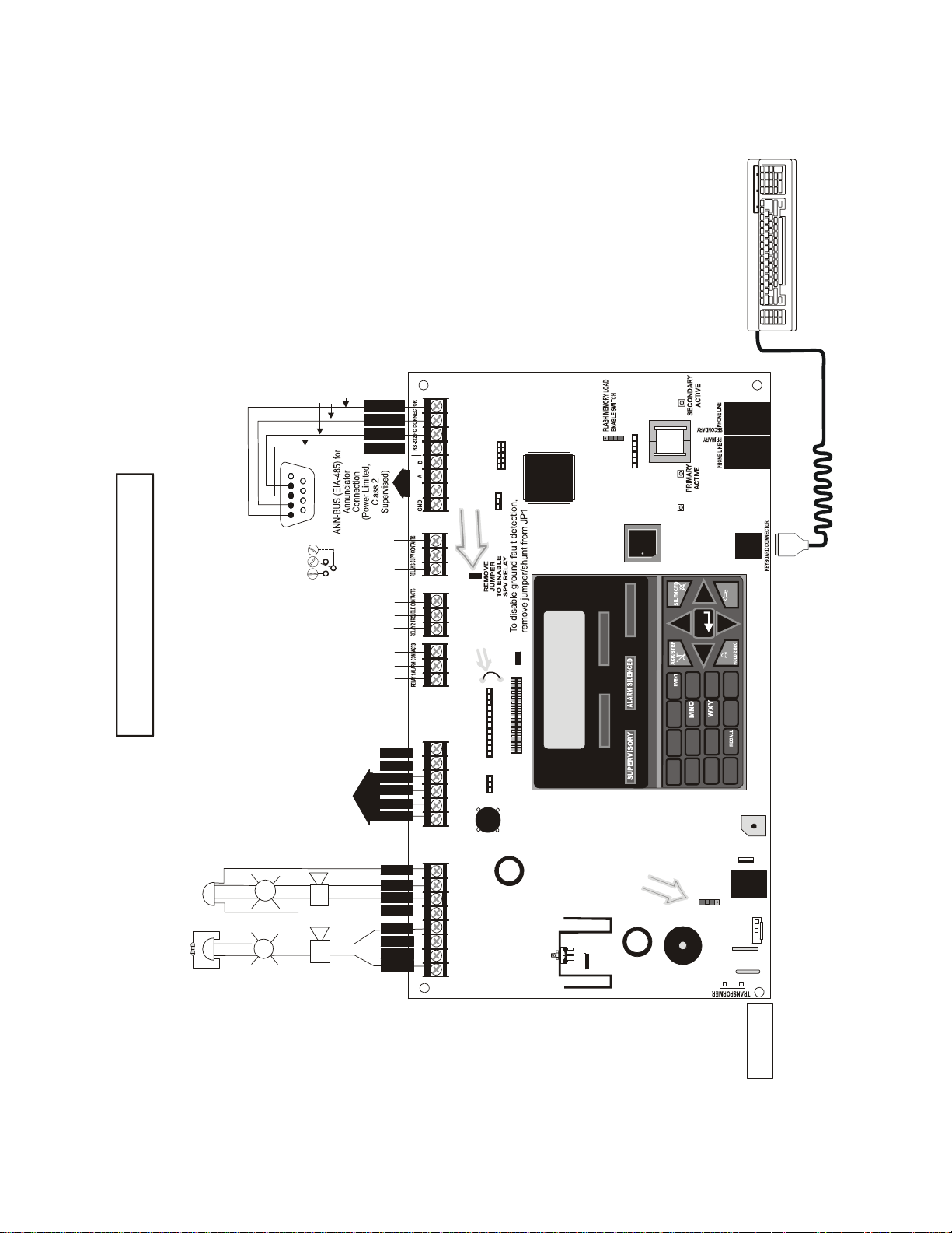
Special Application Power
NAC #1 Shown Style Y (Class B) (Power-Limited, Class 2, Supervised)
NAC #2 Shown Style Z (Class A) (Power-Limit ed, Class 2, Su pervised)
2.5 amps m a x. per circuit . Tota l available current 2.5 amps.
Nonsupervised Contact Ratings:
2.0 amps @ 30 VDC (resistive)
0.5 amps @ 30 VAC (resistive)
Conta c ts shown below in normal
conditi on (AC power with no al ar m ,
trouble or supervisory activity).
A Fail Safe Trouble
relay switches to the
NO position du r i n g
trouble co nd itions and
under loss of all power.
personal computer with FACP
Upload/Download Utility.
50 foot maximum within same room.
(Nonsupervised,
Power-limited (Class 2) Circuit)
Refer to the SLC Wiring
Manual for detailed
information on wiring
addressable devices
for Style 4, 6 and 7.
(Power- Limit ed, Clas s 2
Supervised Ci rcuit)
ELR 4.7K, ½W
Battery
Basic System Connections
Notification Appliance Circuits
2 Programmable Relays &
1 Fixed Trouble Relay
EIA-232 to
personal computer
SLC Loop
NO NC C
NC NO C
NO NC C
Alarm* Trouble
Supervisory*
5 4 3 2 1
9 8 7 6
Green
Black
White
Red
NC NO C
24 VDC, nonpowe r - l im it e d,
supervised, 18 Amp Hour max.
(* )Factory default relay programming
B
+
B
-
BA
+
A
-
A
X
M
T
6
R
C
V
5
G
N
D
8
D
T
R
7
Transformer
Connector
Nonpower-limited,
Supervised
Remove this jumper to enable
Supervisory relay wh en
4XTMF module is installed
NAC #1
-
+
B
+
B
-
1
4
A
+
A
-
23
+
+
NAC #2
B
+
B
-
A
+
A
-
+
+
+
56
78
CAUTION!
HIGH VOLTAGE
1
4
2
3
5
6
JP28
Cut JP28 to
supervise
4XTMF
J11
+
_
SW27
Charger Enable/Disable
Switch (shown in charger
enable position)
9050udlayo90.cdr
For specific UL wiring
information, refer to "UL
Power-limited Wiring
Requirements" on page 45
MS-9050UD PN 52413:B 8/29/07 11
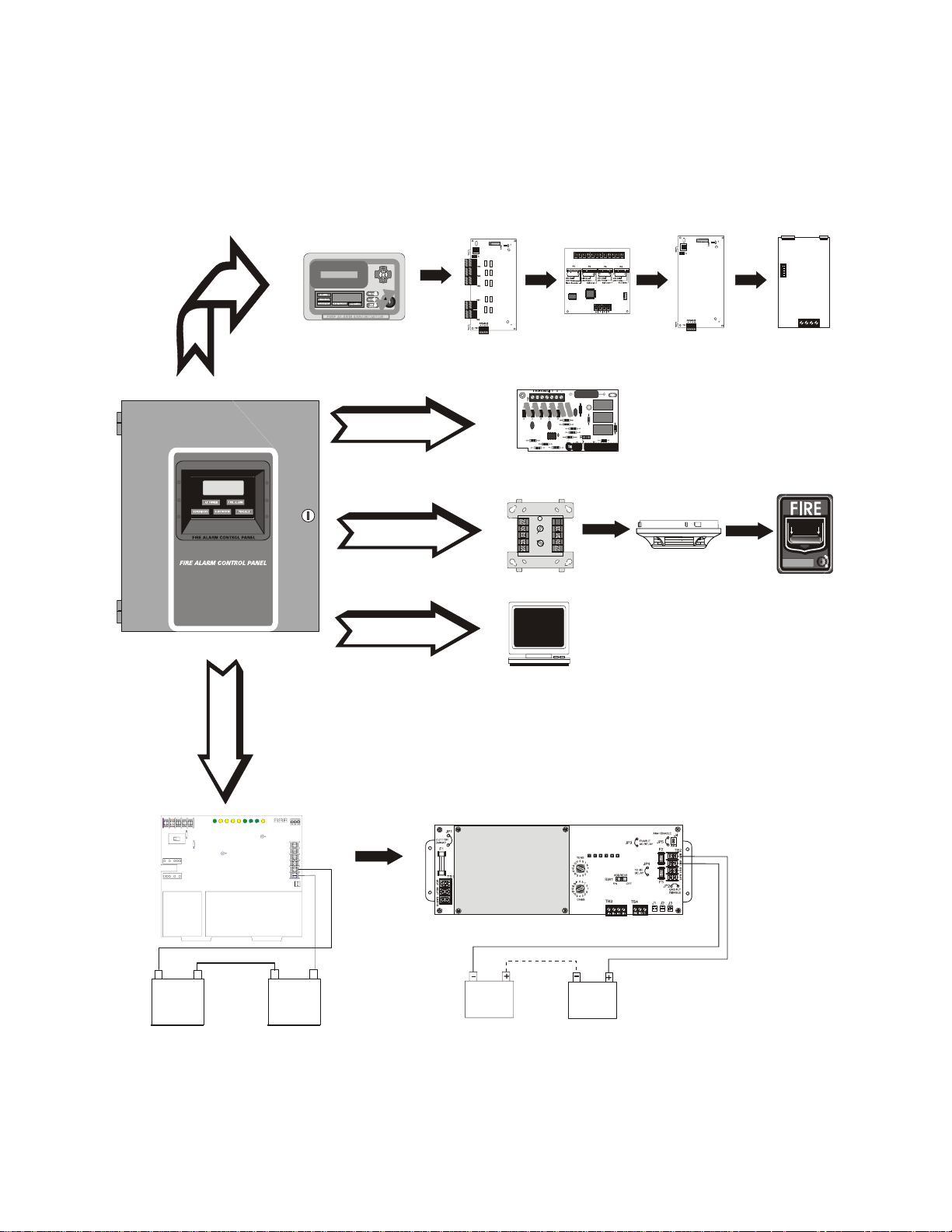
Peripheral Devices
CHG-120F Charger
Doc. #50888
CHG-75 Charger
Doc. #51315
Addressable Devices and SLC Wiring
Doc. #51309
SLC Loop
Battery Connector
ANN-BUS
ANN-80
Text Annunciator
Doc. #52749
ANN-I/O
LED Driver
Doc. #151416
ANN-S/PG
Printer Driver
Doc. #151417
9050UDperi.cdr
ANN-RLY
10 Form-C Relay Card
Doc. #53033
ANN-(R)LED
LED Display
Doc. #53032
4XTMF
Municipal Box Transmitter
RS-232
Local PC

Product Description Features and Options
12 MS-9050UD PN 52413:B 8/29/07
SECTION 1 Product Description
The MS-9050UDis a combination FACP (Fire Alarm Control Panel) and DACT (Digital Alarm
Communicator/Transmitter) all on one circuit board. This compact, cost effective, intelligent
addressable control panel has an extensive list of powerful features. The combination of Fire-Lite’s
newer series devices and legacy 300 Series devices, along with the MS-9050UD FACP, offer the
latest in fire protection technology. The power supply and all electronics are contained on a single
circuit board housed in a metal cabinet, providing a complete fire control system for most
applications. Available accessories include local and remote upload/download software, remote
annunciators and reverse polarity/city box transmitter.
The integral DACT transmits system status (alarms, troubles, AC loss, etc.) to a Central Station via
the public switched telephone network. It also allows remote programming or interrogation of the
control panel using the PK-CD Upload/Download utility via the public switched telephone
network. Any personal computer with Windows
™
XP or newer, and compatible modem with a
speed of 2400 baud or faster and Upload/Download software kit PK-CD, may serve as a Service
T erminal. This allows download of the entire program or upload of the entire program, history file,
walktest data and current status.
Inventory
When the MS-9050UD shipment is received, check to make certain that all parts have been
included in the shipment. The MS-9050UD shipment should consis t of one of each of the
following:
main circu it board with display
chassis with transformer
backbox wit h doo r
plastic bag containing screws, cables, key, etc.
manual
1.1 Features and Options
• Built-in DACT (Digital Alarm Communicator/Transmitter) with remote upload/download
• Single addressable SLC loop which meets NFPA Style 4, 6 and 7 requirements
• 50 addressable device capacity (any combination of addressable detectors and addressable
control/relay/monitor modules totalling 50)
• 20 software zones
• Two onboard NACs (Notification Appli ance Circ ui ts) which can be configured as Style Y
(Class B) or Style Z (Class A) circuits
• 2.5 amps total power for NACs
• 2.7 amps total system power (includes battery charger)
• Two programmable relays and one fixed trouble relay
• Built-in Programmer
• Telephone Line Active LEDs
• Communication Confirmation (Kissoff) LED
• Touchtone/Rotary di aling
• EIA-232 PC interface for local upload/download
• 80-character LCD display (backlit)

Specifications Product Description
MS-9050UD PN 52413:B 8/29/07 13
• Real-time clock/calendar with daylight savings time control
• History file with 500 event capacity
• Advanced fire technology features:
Automatic drift compensation
Maintenance alert
Detector sensitivity test capability (NFPA 72 compliant)
Automa tic devi ce type-code veri fication
Point trouble identification
• Waterflow selection per module point
• Alarm verification selection per detector point
• Walktest, silent or audible
• PAS (Positive Alarm Sequence) per addressable detector and Pre-signal per point (NFPA 72
compliant)
• Silence inhibit timer option per NAC
• Autosilence timer option per NAC
• Continuous, March Time, Temporal or California code for main circuit board NACs with
two-stage capability
• Selectable strobe synchronization per NAC
• Remote Acknowledge, Alarm Silence, Reset and Drill via addressable modules or remote
annunciator
• Auto-program (learn mode) reduces installation time. Reports two devices set to the same
address
• Password and key-protected nonvolatile memory
• User programmable password
• Fully programmable from local keypad or optional keyboard
• SLC operates up to 10,000 ft. (3,000 m) with twisted, unshield ed fire wire
• Compatible with Fire-Lite’ addressable devices (refer to SLC Wiring Manual)
• Compatible with legacy Fire-Lite 300 Series addressable devices (refer to SLC Wiring
Manual)
• Optional 4XTMF module (conventional reverse polarity/city box transmitter)
• Optional ANN-I/O LED Driver module
• Optional ANN-S/PG printer interface module
• Optional ANN-80 remote LCD annunciator
• Optional ANN-LED Annunciator Module annunciates alarm, trouble and supervisory
• Optional ANN-RLED Annunciator Module annunciates alarms only
• Optional ANN-RLY Form-C Relay Module
• Optional Dress Panels (DP-51050)
1.2 Specifications
Refer to Illustration on page 10 for terminal locations and connections.
AC Power - Transformer Connection
MS-9050UD: 120 VAC, 60 Hz, 3.0 amps
Wire size: minimum 14 AWG (2.00 mm
2
) with 600 V insulation
Nonpower-limited, supervised
Battery (Lead Acid Only) - J1
Maximum Charging Circuit: Normal Flat Charge - 27.6 VDC @ 1.2 amp
Maximum Battery Charger Capacity: 18 Amp Hour, (FACP cabinet holds maximum of two 18
Amp Hour batteries)
Minimum Battery: 7 Amp Hour
Nonpower-limited, supervised

Product Description Controls and Indicators
14 MS-9050UD PN 52413:B 8/29/07
SLC Communication Loop - TB2
24 VDC nominal, 27.6 VDC maximum
Maximum length is 10,000 ft. (3,000 m) total twisted, unshielded fire wire
Maximum loop current is 400 mA (short circuit) or 100 mA (normal)
Maximum loop resistance is 40 ohms
Supervised and power-limited circuit
Refer to SLC Loop manual for wiring information
Notification Appliance Circuits - TB1
Terminal Block provides connections fo r two NACs, Style Y (Class B) or
Style Z (Class A)
Special Application power
Power-limited, supervised circuitry
Maximum voltage drop in wiring: 2.0 VDC
Nominal operating voltage: 24 VDC
Current-limit: fuseless, electronic, power-limited circuitry
Maximum signaling current per circuit: 2.5 amps
End-of-Line Resistor: 4.7 kΩ, ½ watt (P/N 71252 UL listed) for Style Y (Class B) NAC
Refer to Fire-Lite Device Compatibility Document for listed compatible devices
Two Programmable Relays and One Fixed Trouble Relay - TB5, TB6 & TB7
Contact rating: 2.0 amps @ 30 VDC (resistive), 0.5 amps @ 30 VAC (resistive)
Form-C relays, nonpower-limited, nonsupervised
Refer to Figure 2.5 on page 43 for information on power-limited relay circuit wiring
EIA-232 - TB3
EIA-232 PC applications connections: Terminal 5 (Receive), 6 (Transmit),
7 (DTR), 8 (Ground)
Power-limited, supervised
ANN-BUS (EIA-485) - TB3
Annunciator connector: Terminal 1 (Ground), 2 (Power), 3 (A), 4 (B)
Nominal Operating Voltage: 24 VDC
Maximum Current (Terminals 1 & 2): 500 mA
Power-limited, supervised
1.2.1 Current Availability
The Notification Appliance Circuits can provide 2.5 amps maximum per circuit. Total available
current for the FACP is 2.7 amps.
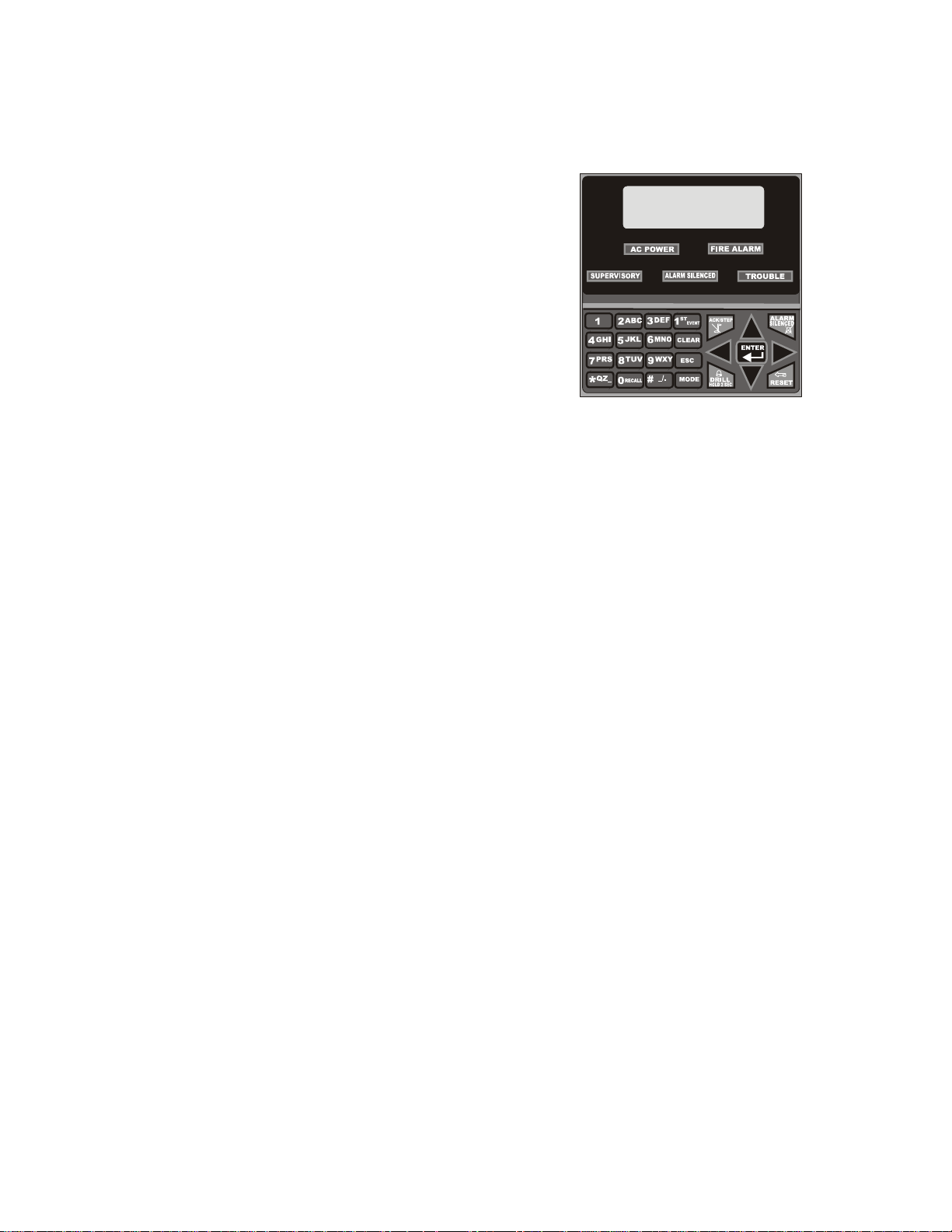
1.3 Controls and Indicators
LCD Display
The FACP uses an 80-character
(4 lines X 20 characters) high viewing angle
LCD display. The display includes a long life
LED backlight that remains illuminated. If AC
power is lost and the system is not in alarm, the
LED backlight will turn off to conserve batteries.
LED Indicators
LED indicators are provided to annunciate the following conditions:
• AC Power (green)
• Fire Alarm (red)
• Supervisory (yellow)
• Trouble (yellow)
• Alarm Silenced signals (yellow)
SYSTEM ALL NORMAL
10:00A 092105
Circuits Product Description
MS-9050UD PN 52413:B 8/29/07 15
Key Panel
Mounted on the main circuit board, the key panel includes a window for the LCD display and LED
indicators as listed above. The key panel, which is visible with the cabinet door closed, has 25
keys, including a 16 key alpha-numeric pad similar to a telephone keypad.
Function keys:
• Acknowledge/Step
• Alarm Silenced
• Drill (Manual Evacuate)
• Reset (lamp test)
Service/program keys:
• Keys labeled 1 to 9
• * key
• # key
• 0 (recall) key
• 1st Event key
• Clear key
• Escape key
• Mode key
• Four cursor keys (up, down, left and right)
• Enter key
Local Piezo Sounder
A piezo sounder provides separate and distinct pulse rates for alarm, trouble and supervisory
conditions.
1.4 Circuits
SLC Communication Loop
One SLC loop is provided on the FACP main circuit board. The SLC loop, configurable for NFPA
Style 4, 6 or 7, provides communication to addressable detectors, monitor (initiating device) and
control (output device) modules. Refer to the SLC Wiring manual for information on wiring
devices.
Output Circuits
The following output circuits are available on the FACP:
• Charger
24 VDC Battery Charger (up to 18 AH batteries)
• NAC (Notification Appliance Circuits)
Two NACs configurable for Style Y (Class B) or Style Z (Class A), are provided with various
programmable features.
Figure 1.1 Membrane/Display Panel
9050udkypd.cdr
Reference
Manual

Product Description Digital Alarm Communicator/Transmitter
16 MS-9050UD PN 52413:B 8/29/07
Relays
One fixed and two fully programmable Form-C dry contact relays are provided. The fixed fail-safe
relay monitors system trouble and the two programmable relays are factory default programmed for
system alarm and system supervisory. Contacts are rated 2.0 amps @ 30 VDC (resistive) and 0.5
amps @ 30 VAC (resistive). The programmable relays can be programmed for the following
operations:
• fire alarm
• silenceable alarm
• trouble
• supervisory
• supervisory auto-resettable
• DACT communication failure
• process monitor
• process monitor auto-resettable
• hazard alert
• medical alert
•AC loss
1.5 Digital Alarm Communicator/Transmitter
T wo modular phone jacks allow easy connection to telephone lines. Modular jacks are labeled PH1
for Primary Phone Line and PH2 for Secondary Phone Line. Two telephone line active red LEDs
are provided as well as a green Kissoff LED. The integral digital communicator provides the
following functions:
• Line Seizure: takes control of the phone lines disconnecting any premises phones
• Off/On Hook: performs on and off-hook status to the phone lines
• Dialing the Central Station(s) number: default is Touch-Tone
®
, programmable to rotary
• For tone burst or touchtone type formats: discern proper Ack and Kissoff tone(s). The
frequency and time duration of the tone(s) varies with the transmission format. The control
panel will adjust accordingly.
• Communicate in the following formats:
12 Tone Burst types: 20 pps
(3+1, 4+1, 4+2, 3+1 Exp., 4+1 Exp., 4+2 Exp.)
3 Touchtone Types
4+1 Ademco Express
4+2 Ademco Express
Ademco Contact ID
Components Product Description
MS-9050UD PN 52413:B 8/29/07 17
1.6 Components
Main Circuit Board
The main circuit board contains the system’s CPU, power supply, other primary components and
wiring interface connectors. The 4XTMF option module plugs in and is mounted to the main
circuit board. The circuit board is delivered mounted to a chassis in the MS-9050UD backbox
(refer to circuit board illustration on page 10).
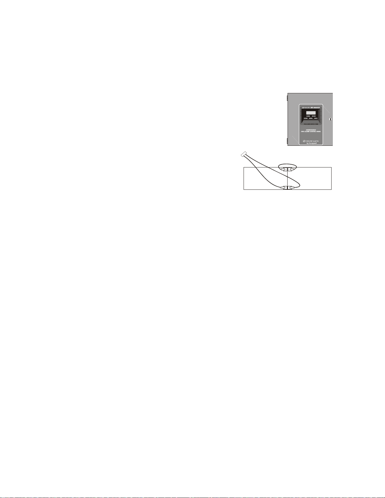
Cabinet
The MS-9050UD backbox provides space for two batteries (up to 18 Amp
Hour). Ample knockouts are provided for system wiring. Also available is
an optional dress panel, which mounts to the inside of the cabinet (required
by ULC for Canadian installations). The dress panel must be installed to
meet FM requirements.
Batteries
The MS-9050UD cabinet provides space for two
batteries (up to 18 Amp Hour). Batteries must be
ordered separately.
1.6.1 Intelligent Addressable
Detectors: Newer Series
Intelligent, addressable detectors provide information to the control panel on an SLC Signaling
Line Circuit (refer to the SLC Wiring Manual for detailed information on addressable devices,
device installation, wiring and operation). This allows the control panel to continually process the
information to determine the status (alarm, trouble, maintenance or normal) of each detector . Each
detector responds to an SLC address that is set in the detector head using built-in rotary decimal
switches. Note that a blinking LED on an intelligent detector indicates communication between the
detector and the control panel. Refer to the Fire-Lite Device Compatibility Document for a list of
approved conventional detectors.
1.6.2 Intelligent Addressable Modules: Newer Series
The newer series of Control Modules and Monitor Modules provide an interface between the
control panel and conventional notification and initiating devices. Each module can be set to
respond to an address with built-in rotary switches. A blinking LED on a monitor module indicates
communication between the module and the control panel. These devices can also be used when
installed on older systems. Refer to the SLC Wiring Manual for information on addressable
devices. Refer to the Fire-Lite Device Compatibility Document for a list of approved conventional
notification and initiating devices.
1.6.3 300 Series Intelligent Addressable Devices
Fire-Lite’s 300 Series Intelligent Addressable Devices are fully compatible with the MS-9050UD
FACP. Refer to the SLC Wiring Manual for device information.
1.6.4 Device Accessories
End-of-Line Resistor Assembly
Refer to the SLC Wiring Manual for device information. The 47 kΩ End-of-Line Resistor
assembly (P/N: R-47K) is used to supervise the MMF-300, MDF-300, MMF-301 and CMF-300
module circuits. The 3.9 kΩ End-of-Line Resistor assembly is used to supervise the MMF-302
module circuit. The End-of-Line resistors are included with each module.
See Page
MS_9050UD.cdr
-
-
+
+
Battery Cable P/N 75203
9200batt.cdr
Reference
Manual

Product Description Optional Modules
18 MS-9050UD PN 52413:B 8/29/07
Power Supervision Relay
The UL listed End-of-Line power supervision relay is used to supervise the power to 4-wire smoke
detectors and notification appliances.
N-ELR Mounting Plate
The N-ELR is a single End-of-Line resistor plate which is required for use in Canada. An ELR,
which is supplied with each module and fire alarm control panel, is mounted to the ELR plate.
Resistors mounted to the N-ELR plate can be used for the supervision of a monitor and control
module circuit.
1.7 Optional Modules
The MS-9050UD main circuit board includes option module connectors for the followin g mo dule:
4XTMF Transmitter Module
The 4XTMF provides a supervised output for local energy municipal box transmitter, alarm and
trouble reverse polarity. It includes a disable switch and disable trouble LED. A jumper on the
module is used to select an option which allows the reverse polarity circuit to open with a system
trouble condition if no alarm condition exists. The module plugs into connectors J8 and J9 which
are located near the top center of the main circuit board. When the 4XTMF module is installed,
Jumper JP28, on the main circuit board, must be cut to allow supervision of the module.
1.8 Accessories
1.8.1 PK-CD Programming Utility
The PK-CD Programming Utility can be used to locally or remotely program an MS-9050UD
directly from most IBM compatible personal computers (PC), running Windows
™ XP (or newer).
MS-9050UD program files can also be created and stored on the PC and then downloaded to the
control panel. The PK-CD Kit includes the MS-9050UD Windows-based Programming Utility
software on CD-ROM with on-line help file. A serial cable (P/N: PRT/PK-CABLE), which must
be purchased separately, is required for local connection of the PC to the RS-232 (PC/Printer)
terminals at TB3 of the MS-9050UD main circuit board. Remote programming requires that the
PC have a 2400 baud (or faster) modem.
Important: Remote modification of FACP programming requires that the panel be enabled for
remote download (refer to "Remote Download" on page 177). Remote interrogation of panel
programming, history logs, detector status, etc., is possible without enabling the remote download
option.
1.8.2 Dress Panel
An optional dress panel (DP-51050) is available for the MS-9050UD (required by ULC for
Canadian installations). The dress panel restricts access to the system wiring while allowing access
to the key panel. The dress panel must be installed to meet FM requirements.
1.8.3 Trim Ring
An optional Trim Ring (TR-CE) is available for semi-flush mounting of the FACP backbox.

ANN-BUS Devices Product Description
MS-9050UD PN 52413:B 8/29/07 19
1.9 ANN-BUS Devices
WARNING! Disconnect all sources of power (AC and DC) before installing or removing any
modules or wiring.
A variety of optional devices can be connected to the FACP ANN-BUS communication circuit.
Compatible devices include:
• ANN-80 LCD Annunciator
• ANN-S/PG Serial/Parallel Printer Interface Module
• ANN-I/O LED Driver Module
• ANN-LED Annunciator Module (alarm, trouble, supervisory LEDs)
• ANN-RLED Annunciator Module (red alarm LEDs only)
• ANN-RLY Relay Module
1.9.1 ANN-BUS Wiring
This section contains information on calculating ANN-BUS wire distances and the types of wiring
configurations (Class B).
1.9.1.1 Calculating Wiring Distance for ANN-BUS Modules
The following instructions will guide the installer in determining the type of wire and the
maximum wiring distance that can be used with FACP ANN-BUS accessory modules.
To calculate the wire gauge that must be used to connect ANN-BUS modules to the FACP, it is
necessary to calculate the total worst case current draw for all modules on a single 4-conductor
bus. The total worst case current draw is calculated by adding the individual worst case
currents for each module. The individual worst case values are shown in the following table:
Note: Total worst case current draw on a single ANN-BUS cannot exceed 0.5 amp. If current
draw exceeds 0.5 amps, refer to "Powering ANN-BUS Devices fr om Auxiliary Power Supply"
on page 22.
Model Number Worst Case Current Draw
ANN-80 LCD Annunciator 0.040 amps
ANN-S/PG Serial/Parallel Printer Interface Module 0.040 amps
ANN-I/O LED Driver Module 0.200 amps
ANN-RLY Relay Module 0.075 amps
ANN-(R)LED Annunciator Module 0.068 amps

Product Description ANN-BUS Devices
20 MS-9050UD PN 52413:B 8/29/07
After calculating the total worst case current draw, Table 1.1 specifies the maximum distance
the modules can be located from the FACP on a single wire run. The table ensures 6.0 volts of
line drop maximum. In general, the wire length is limited by resistance, but for heavier wi re
gauges, capacitance is the limiting factor. These cases are marked in the chart with an asterisk
(*). Maximum length can never be more than 6,000 feet (1,800 m), regardless of gauge used.
The formula used to generate this chart is shown in the note below.
Note: The following formulas were used to generate the wire distance chart:
Exception: When using the ANN-RLY module, the installer must ensure that the maximum
24VDC power line drop does not exceed 0.3 volts. This results in the following wiring
limitations:
Wiring Distance: ANN-BUS Modules to FACP
Total Worst Case
Current Draw (amps)
22 Gauge 18 Gauge 16 Gauge 14 Gauge
0.100 1,852 ft. 4,688 ft. * 6,000 ft. *6,000 ft.
0.200 926 ft. 2,344 ft. 3,731 ft. 5,906 ft.
0.300 617 ft. 1,563 ft. 2,488 ft. 3,937 ft.
0.400 463 ft. 1,172 ft. 1,866 ft. 2,953 ft.
0.500 370 ft. 938 ft. 1,493 ft. 2,362 ft.
Table 1.1 Wiring Distances
6.0 Volts
Maximum Resistance (Ohms) = Total Worst Case Current Draw (amps)
Maximum Wire Length (feet) = Maximum Resistance (Ohms) *500
(6,000 feet maximum) Rpu
where: Rpu = Ohms per 1,000 feet for various Wire Gauges (see table below)
Wire Gauge Ohms per 1,000 feet (Rpu)
22 16.2
18 6.4
16 4.02
14 2.54
Wire Gauge Maximum Wire Length
18 312 feet
16 497 feet
14 787 feet
12 1,250 feet
ANN-BUS Devices Product Description
MS-9050UD PN 52413:B 8/29/07 21
Wiring Distance Calculation Example:
Suppose a system is configured with the following ANN-BUS modules:
• 3 ANN-80 Remote Fire Annunciators
• 1 ANN-S/PG Serial/Parallel Printer Interface Module
• 1 ANN-I/O LED Driver Module
The total worst case current is calculated as follows:
Using this value and referring to the Wiring Distance Table 1.1 on page 20, it can be found that
the available options are:
463 feet maximum using 22 Gauge wire
1,172 feet maximu m using 18 Gauge wire
1,866 feet maximu m using 16 Gauge wire
2,953 feet maximu m using 14 Gauge wire
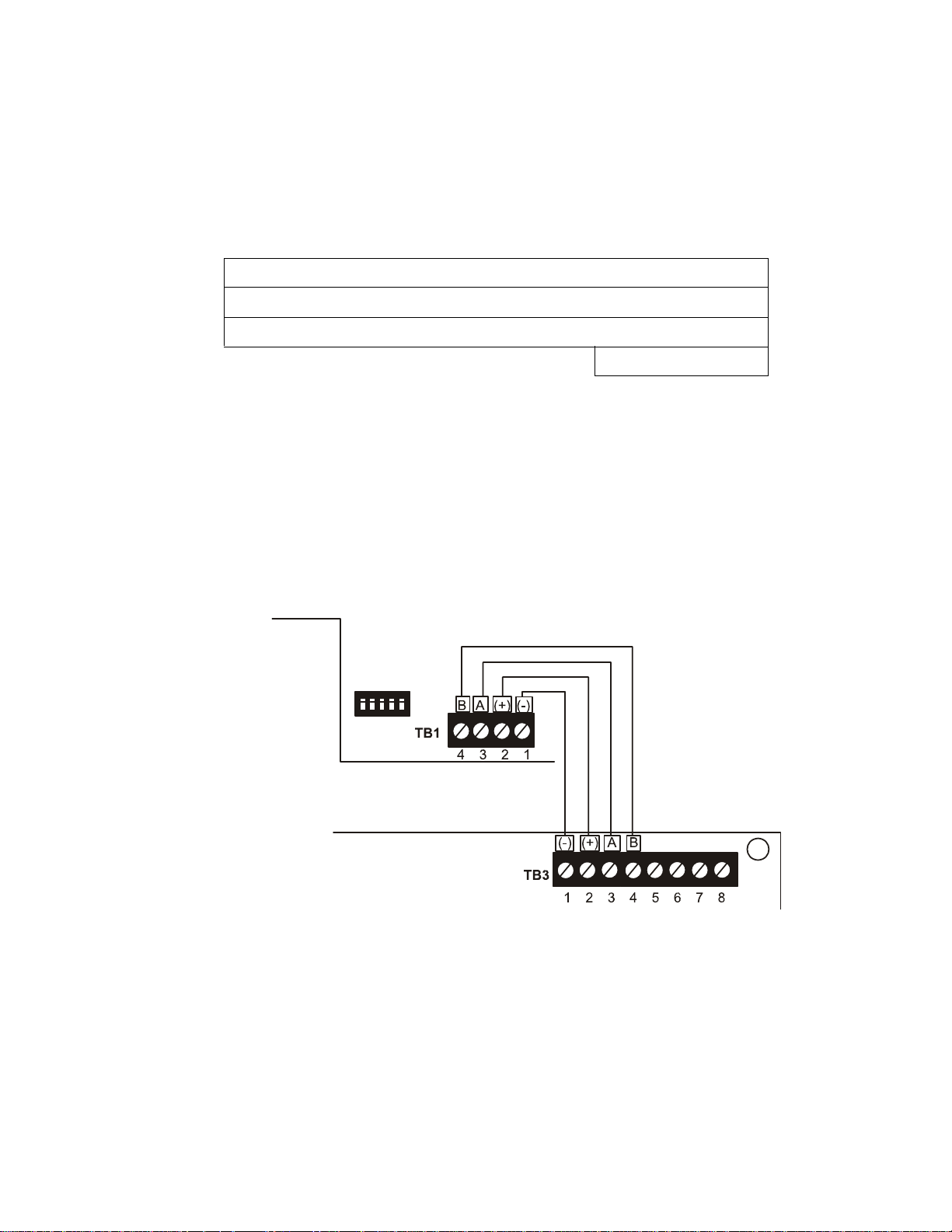
1.9.1.2 Wiring Configuration
Figure 1.2 illustrates the wiring between the FACP and ANN-BUS devices.
ANN-80 Current Draw = 3 X 0.040 amps = 0.120 amps
ANN-S/PG Current Draw = 1 X.0.040 amps = 0.040 amps
ANN-I/O Current Draw = 1 X.0.200 amps = 0.200 amps
Total Worst Case Current Draw = 0.360 amps
Figure 1.2 FACP wiring to ANN-BUS Device
ANN-BUS Device
MS-9050UD
ANN-BUS and power wiring are
supervised and power-limited
Product Description ANN-BUS Devices
22 MS-9050UD PN 52413:B 8/29/07
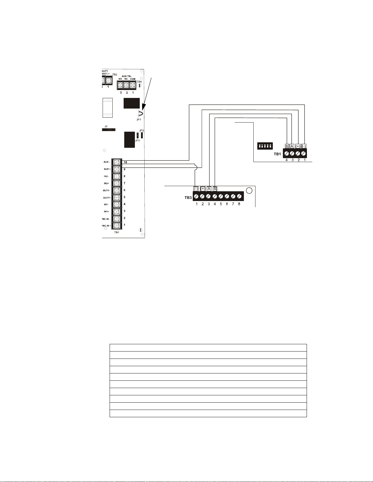
1.9.1.3 Powering ANN-BUS Devices from Auxiliary Power Supply
Figure 1.3 illustrates the powering of ANN-BUS devices from an auxiliary power supply such
as the FCPS-24FS6/8, when the maximum number of ANN-BUS devices exceeds the ANN-
BUS power requirements.
1.9.2 ANN-BUS Device Addressing
Each ANN-BUS device requires a unique address (ID Number) in order to communicate with the
F ACP. A 5-position DIP switch on each device is used to set this address. The address set for these
devices must also be programmed at the FACP for the specific device (refer to the programming
section titled "ANN-BUS" on page 104).
A maximum of 8 devices can be connected to the FACP ANN-BUS communication circuit. Device
addresses do not need to be sequential and can be set to any number between 01 and 08. Note that
00 is not a valid address. The following table shows the DIP switch setting for each address.
Note: Switch 5 must be set to OFF for ANN-BUS devices to be recognized.
Address Switch 5 Switch 4 Switch 3 Switch 2 Switch 1
not valid OFF OFF OFF OFF OFF
01 OFF OFF OFF OFF ON
02 OFF OFF OFF ON OFF
03 OFF OFF OFF ON ON
04 OFF OFF ON OFF OFF
05 OFF OFF ON OFF ON
06 OFF OFF ON ON OFF
07 OFF OFF ON ON ON
08 OFF ON OFF OFF OFF
Figure 1.3 Powering ANN-BUS Devices from FCPS-24FS6/8
ANN-80
MS-9050UD
FCPS-24FS6/8
-24 VDC
+24 VDC
ANN-BUS
Cut Ground Fault Detection jumper JP1 (FACP monitors for ground faults)
ANN-BUS and power wiring are
supervised and power-limited

ANN-BUS Devices Product Description
MS-9050UD PN 52413:B 8/29/07 23
1.9.3 ANN-80 Remote Fire Annunciator
The ANN-80 Annunciator is a compact, 80 character, backlit LCD remote fire annunciator which
mimics the FACP display. It also provides system status indicators for AC Power, Alarm, Trouble,
Supervisory and Alarm Silenced conditions. Communication between the ANN-80 and FACP is
accomplished over a two wire serial interface employing the ANN-BUS communication format.
The devices are powered, via two additional wires, from either the host FACP or remote UL-listed,
filtered, power supply.
1.9.3.1 Specifications
• Operating Voltage Range: 18 VDC to 28 VDC
• Current Consumption @ 24 VDC nominal (filtered and nonresettable):
Normal /Standby (no activity): 37.0 mA
Trouble: 39.0 mA
Alarm: 40.0 mA
AC Fail ( not backlit): 15.0 mA
• For use indoors in a dry location
1.9.3.2 Installation
Ensure that all power (AC and DC) has been removed from the FACP before installing the
annunciator.
1.9.3.3 Mounting
The ANN-80 can be surface or semi-flush mounted to a single, double or 4” square electrical
box. Select and remove the appropriate knockout(s), pull the necessary wires through the
knockouts and mount the annunciator in or on the wall depending on the type of installation
desired.
The ANN-80 cover must be attached to the annunciator backplate before mounting the
annunciator to the electrical box/wall. The cover cannot be reattached or removed after the
annunciator has been mounted.
1.9.3.4 Opening/Closing Annunciator
The following procedure details the steps used to open the annunciator in order to access the
terminal block and DIP switches (refer to figure below):
1. Turn the key switch to the ON (Unlocked) position by turning the key counter-clockwise
2. Push in the snap latch located on the right side of the unit while pulling the cover open
3. T o close the cover, make certain the key switch is in the ON (Unlocked) position. Swing the
cover closed, snapping it shut
4. Turn the key switch to the OFF (Locked) position by turning clockwise and remove the key
Key switch shown in ON position
Press in latch and pull
annunciator cover open
Annunciator cover with LCD display
Annunciator backplate
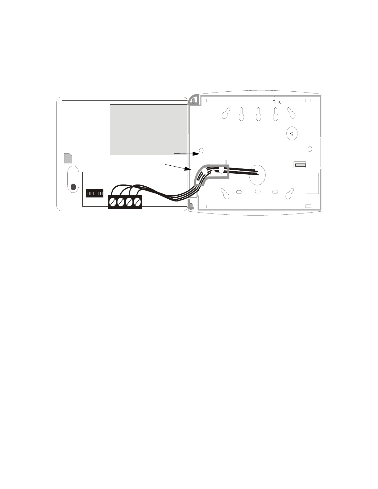
Product Description ANN-BUS Devices
24 MS-9050UD PN 52413:B 8/29/07
1.9.3.5 Wiring ANN-80 to FACP
The following steps can be used as a guide to wire the annunciator . Make certain all power has
been removed from the FACP prior to annunciator installation.
1. Route wires from hole in backplate, through wiring chan nel and then to ANN-80 terminal
block TB1
2. Remove appropriate amount of wire insulation
3. Connect the wiring from the F ACP ANN-BUS to annunciator TB1 terminals 3 (A) & 4 (B).
Make certain to connect A to A and B to B
4. If appropriate, connect the wiring going to the next device on the ANN-BUS to TB1
terminals 3 & 4. Make certain to connect A to A and B to B
5. Connect the wiring from the 24 VDC power source to annunciator TB1 terminals 1 (-) & 2
(+). Make certain to observe proper polarity
6. If appropriate, connect the power wiring going to the next device to terminals
1 (-) & 2 (+). Make certain to observe proper polarity
7. After all connections are made, remove extra wire from inside of annunciator by dressing it
neatly through wire channel, with any excess wire pushed back through hole into electrical
box
wiring channel
wires
TB1
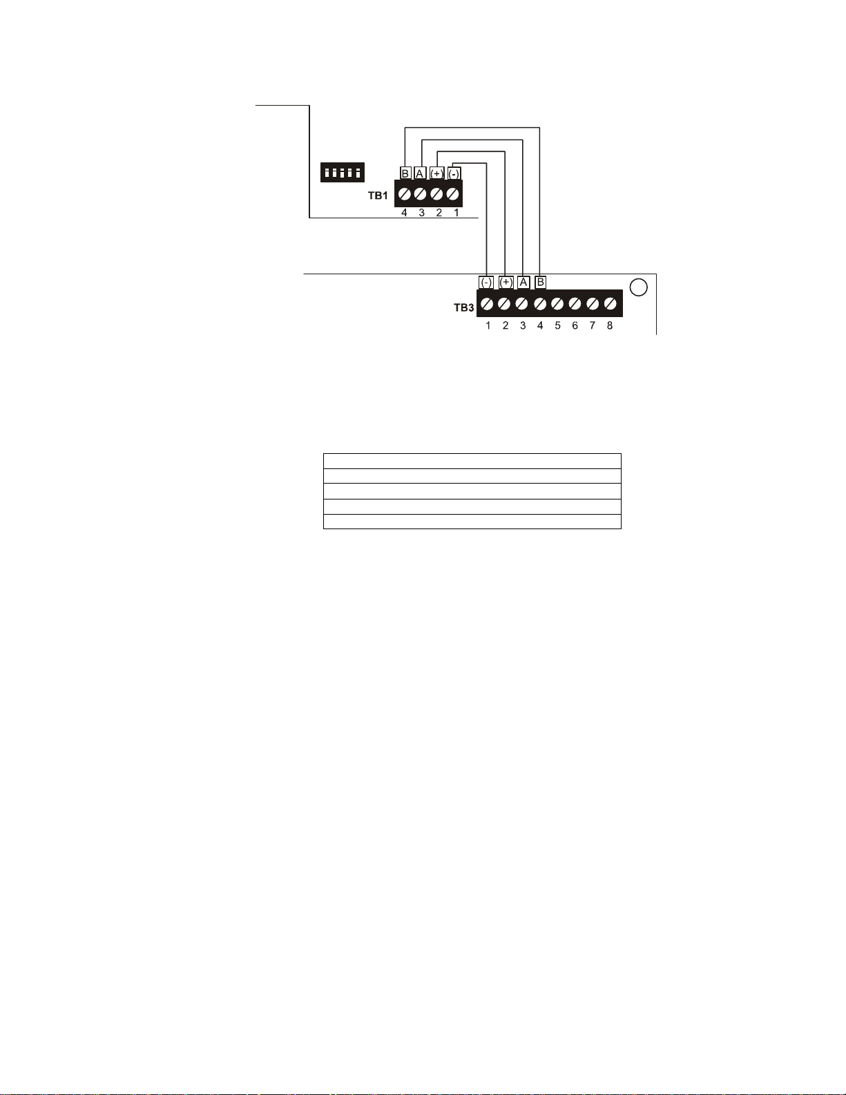
ANN-BUS Devices Product Description
MS-9050UD PN 52413:B 8/29/07 25
The following table shows the ANN-80 connections to the MS-9050UD.
Programming
Following installation and wiring of the ANN-80 LCD annunciator to the FACP, the annunciator
must added to the system via FACP programming. Refer to the programming section titled "ANN-
BUS" on page 104 in this manual for detailed programming information. Select the LCD option
for programming.
Trouble Response
If the ANN-80 is installed but the ANN-BUS is not enabled at the F ACP, the ANN-80 will indicate
a trouble condition by NOT turning on its AC Power indicator. The LCD will also display Key Bus
Trouble and the piezo will sound approximately once every 10 seconds. Note that the FACP will
provide no indication of an ANN-80 trouble.
To clear the ANN-80 trouble condition, enable the ANN-BUS and program the address
corresponding to the address set on the ANN-80 at the FACP.
MS-9050UD (TB3) ANN-80 (TB1)
Terminal 1 GND (-) Terminal 1 (-)
Terminal 2 PWR (+) Terminal 2 (+)
Terminal 3 A (ANN-BUS) Terminal 3 (A)
Terminal 4 B (ANN-B US) Terminal 4 (B)
Figure 1.4 ANN-80 Wiring to FACP
FACP
ANN-80
ANN-BUS and power wiring are
supervised and power-limited
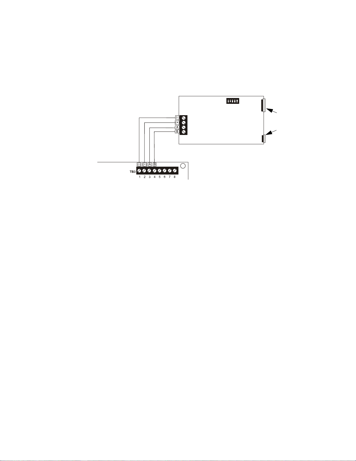
Product Description ANN-BUS Devices
26 MS-9050UD PN 52413:B 8/29/07
1.9.4 ANN-S/PG Serial/Parallel Interface Module
The ANN-S/PG Serial/Parallel Interface module allows the connection of a serial or parallel printer
to the FACP for a real-time log of system events, detector status reports and event history. The
module is provided with a plastic enclosure for surface mounting. Proceed with the installation as
described in the following:
1. Ensure that all power (AC and DC) has been removed from the FACP.
2. Connect the ANN-S/PG to the FACP as illustrated in Figure 1.5
3. Using the DIP switches on the back of the ANN-S/PG module, assign an ID number
(address) to the module
4. Select the address and configuration options for the ANN-S/PG module as described in the
Programming section of this manual (refer to "ANN-BUS" on page 104)
Note that the Auto-configure feature allows the programmer to quickly bring all installed
ANN-BUS modules online (refer to "Auto-Configure" on page 115)
5. Connect a printer to the ANN-S/PG Parallel or Serial connectors (refer to Figure 1.5). Only
one printer can be connected.
1.9.4.1 Specifications
• Operating Voltage: 24 VDC
• Current (Alarm and Standby): 45 mA
• Ambient Temperature: 32
o
F to 120
o
F (0
o
C to 49
o
C)
• Max. Wiring Distance from FACP: 6,000 ft. (1,800 m)
• Mounting: Surface
• Dimensions: 6”W x 7-3/4”H x 1-7/16”D (15.2 cm W x 19.7 cm H x 3.7 cm D)
• For indoor use in a dry location only
1.9.4.2 PRN 6 Printer Installation
When connected to the FACP via the ANN-S/PG module, the PRN prints the status changes
within the control panel and time-stamps the printout with the time of day and date that the
event occurred. It provides 80 columns of data on standard 9” x 11” tractor-feed paper. This
section contains information on connecting a printer to the control panel and setting the printer
options.
Figure 1.5 ANN-S/PG Connection to FACP
ANN-S/PG Module
MS-9050UD
Cable
Connectors for
connection to
printer
Parallel
Serial
ANN-BUS and power wiring are
supervised and power-limited

ANN-BUS Devices Product Description
MS-9050UD PN 52413:B 8/29/07 27
1.9.4.2.1 Connecting PRN 6 Printer
Remote printers require a primary AC power source. If required for the fire alarm system
configuration (for example, a Proprietary Fire Alarm System), a remote printer requires a
secondary power source (battery backup). Since a secondary power source is not provided as a
standard feature, a separate UL-listed Uninterruptible Power Supply (UPS) should be used.
The building emergency power supply may be used, as long as it meets the power continuity
requirements of NFPA 72. Refer to NFPA 72 for further details.
Connect the remote printer to the FACP via the ANN-S/PG module using a standard DB-25
cable. One end of the cable will plug into the DB-25 connector on the PRN printer and the
other end plugs into the parallel connector on the ANN-S/PG module. Note that the 9-pin DB-
9 port on the ANN-S/PG is used to connect a serial printer. The 25-pin port is used for a
Centronics parallel printer cable. Connect either a serial or parallel printer, but not both at the
same time.
1.9.4.2.2 Setting Printer Options
Refer to the documentation supplied with the PRN 6 printer for instructions on using the printer
menu controls. Set the printer options (under the menu area) as shown in the following table:
TABLE 1-3:PRN Setup Options
Option Setting Option Setting
Font HS Draft CPI 10CPI
LPI 6 LPI Skip 0.5
ESC Character ESC Emulate Epson FX-850
Bidirectional Copy ON I/O
CG-TAB Graphic Buffer 40K
Country E-US ASCII Serial
Auto CR OFF Baud 9600 or 2400
Color Option Not Installed Format 7 Bit, Even, 1 Stop
Formien Protocol XON/XOFF
Lines 6LPI=60 Character Set Standard
Standard Exec 10.5 SI.Zero On
Auto LF On
PAPER
BIN 1 12/72”
BIN 2 12/72”
SINGLE 12/72”
PUSH TRA 12/72”
PULL TRA 12/72”
PAP ROLL 12/72”
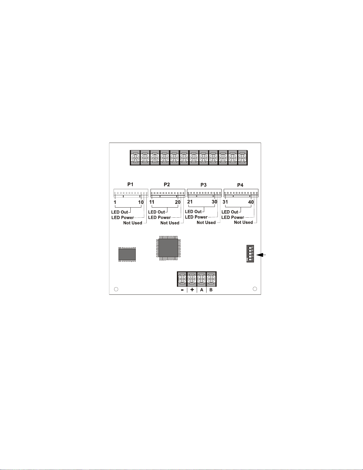
Product Description ANN-BUS Devices
28 MS-9050UD PN 52413:B 8/29/07
1.9.5 ANN-I/O LED Driver Module
The ANN-I/O is an LED driver module that can be used in a wide variety of applications, including
as an interface with most customized graphic annunciators. The ANN-I/O can drive up to 40
LEDs. The module is provided with a plastic enclosure for mounting inside the annunciator or
accessory box. The following sections describe hardware installation. Refer to the section titled
"ANN-BUS" on page 104 for programming information.
1.9.5.1 ANN-I/O Board Layout
Figure 1.1 illustrates the ANN-I/O board showing locations of screw terminals for connection
to the FACP, pin connectors for connecting LEDs and the DIP switch for selecting the ANN-
BUS ID number.
1.9.5.2 Specifications
• Max. ANN-BUS Voltage: 28 VDC
• Max. Current:
Alarm: 200 mA
Standby: 35 mA
Each LED: 10 mA
• Operating Temperature: 32
o
F to 120
o
F (0
o
C to 49
o
C)
• For indoor use in a dry location only
Figure 1.1 ANN-I/O Board Layout
ANN-BUS (ID#)
Address DIP
switch
ANN-BUS Connector
Terminals not used (future)
ann-IObrd.cdr

ANN-BUS Devices Product Description
MS-9050UD PN 52413:B 8/29/07 29
1.9.5.3 ANN-I/O Connection to FACP
The ANN-I/O connects to the FACP via the ANN-BUS as illustrated in Figure 1.2. After the
ANN-I/O is connected to the panel, it must be added to the system via FACP programming.
Refer to the section titled "Modules Installed" on page 105.
Figure 1.2 ANN-I/O Connection to FACP
ANN-I/O Module
MS-9050UD
ANN-BUS and power wiring are
supervised and power-limited
ann-IOtoFACP.cdr
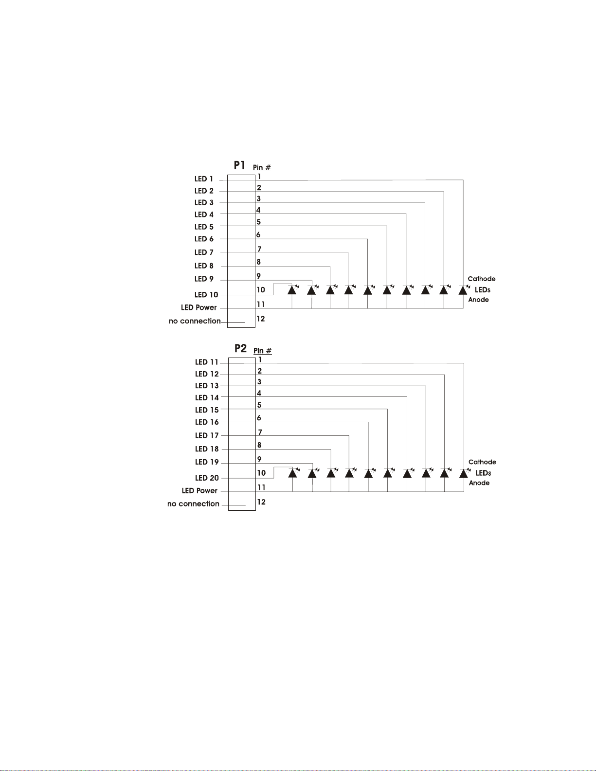
Product Description ANN-BUS Devices
30 MS-9050UD PN 52413:B 8/29/07
1.9.5.4 ANN-I/O Module LED Wiring
There are four 12-pin connectors on the ANN-I/O module for connecting LEDs. Each set of 10
LEDs get their power from Pin 11 of the corresponding connector. Internal resistors are sized
so that there is approximately 10 mA of current for each LED. No series resistors are required.
LED outputs can be mapped to output circuits. Refer to the programming section titled
"Modules Installed" on page 105 of this manual.
The LEDs are wired as illustrated in Figure 1.3. Note that the illustration depicts only
connectors P1 and P2. Wiring is identical for P3 (LEDs 21-30) and P4 (LEDs 31-40).
Figure 1.3 ANN-I/O Board Layout
annI-Oleds.cdr
 Loading...