


 Loading...
Emergency Command Center
ECC-50/100
ECC-50/100E
Instruction Manual
Document LS10001-000FL-E |
|
4/10/2013 |
Rev: A |
P/N LS10001-000FL-E:A |
ECN 13-186 |
Fire Alarm & Emergency Communication System Limitations
While a life safety system may lower insurance rates, it is not a substitute for life and property insurance!
An automatic fire alarm system—typically made up of smoke detectors, heat detectors, manual pull stations, audible warning devices, and a fire alarm control panel (FACP) with remote notification capability—can provide early warning of a developing fire. Such a system, however, does not assure protection against property damage or loss of life resulting from a fire.
An emergency communication system—typically made up of an automatic fire alarm system (as described above) and a life safety communication system that may include an autonomous control unit (ACU), local operating console (LOC), voice communication, and other various interoperable communication meth- ods—can broadcast a mass notification message. Such a system, however, does not assure protection against property damage or loss of life resulting from a fire or life safety event.
The Manufacturer recommends that smoke and/or heat detectors be located throughout a protected premises following the recommendations of the National Fire Protection Association Standard 72 (NFPA 72), manufacturer's recommendations, State and local codes, and the recommendations contained in the Guide for Proper Use of System Smoke Detectors, which is made available at no charge to all installing dealers. This document can be found at http://www.systemsensor.com/ appguides/. A study by the Federal Emergency Management Agency (an agency of the United States government) indicated that smoke detectors may not go off in as many as 35% of all fires. While fire alarm systems are designed to provide early warning against fire, they do not guarantee warning or protection against fire. A fire alarm system may not provide timely or adequate warning, or simply may not function, for a variety of reasons:
Smoke detectors may not sense fire where smoke cannot reach the detectors such as in chimneys, in or behind walls, on roofs, or on the other side of closed doors. Smoke detectors also may not sense a fire on another level or floor of a building. A second-floor detector, for example, may not sense a first-floor or basement fire.
Particles of combustion or “smoke” from a developing fire may not reach the sensing chambers of smoke detectors because:
•Barriers such as closed or partially closed doors, walls, chimneys, even wet or humid areas may inhibit particle or smoke flow.
•Smoke particles may become “cold,” stratify, and not reach the ceiling or upper walls where detectors are located.
•Smoke particles may be blown away from detectors by air outlets, such as air conditioning vents.
•Smoke particles may be drawn into air returns before reaching the detector.
The amount of “smoke” present may be insufficient to alarm smoke detectors. Smoke detectors are designed to alarm at various levels of smoke density. If such density levels are not created by a developing fire at the location of detectors, the detectors will not go into alarm.
Smoke detectors, even when working properly, have sensing limitations. Detectors that have photoelectronic sensing chambers tend to detect smoldering fires better than flaming fires, which have little visible smoke. Detectors that have ionizing-type sensing chambers tend to detect fast-flaming fires better than smoldering fires. Because fires develop in different ways and are often unpredictable in their growth, neither type of detector is necessarily best and a given type of detector may not provide adequate warning of a fire.
Smoke detectors cannot be expected to provide adequate warning of fires caused by arson, children playing with matches (especially in bedrooms), smoking in bed, and violent explosions
(caused by escaping gas, improper storage of flammable materials, etc.).
Heat detectors do not sense particles of combustion and alarm only when heat on their sensors increases at a predetermined rate or reaches a predetermined level. Rate-of-rise heat detectors may be subject to reduced sensitivity over time. For this reason, the rate-of-rise feature of each detector should be tested at least once per year by a qualified fire protection specialist. Heat detectors are designed to protect property, not life.
IMPORTANT! Smoke detectors must be installed in the same room as the control panel and in rooms used by the system for the connection of alarm transmission wiring, communications, signaling, and/or power. If detectors are not so located, a developing fire may damage the alarm system, compromising its ability to report a fire.
Audible warning devices such as bells, horns, strobes, speakers and displays may not alert people if these devices are located on the other side of closed or partly open doors or are located on another floor of a building. Any warning device may fail to alert people with a disability or those who have recently consumed drugs, alcohol, or medication. Please note that:
•An emergency communication system may take priority over a fire alarm system in the event of a life safety emergency.
•Voice messaging systems must be designed to meet intelligibility requirements as defined by NFPA, local codes, and Authorities Having Jurisdiction (AHJ).
•Language and instructional requirements must be clearly disseminated on any local displays.
•Strobes can, under certain circumstances, cause seizures in people with conditions such as epilepsy.
•Studies have shown that certain people, even when they hear a fire alarm signal, do not respond to or comprehend the meaning of the signal. Audible devices, such as horns and bells, can have different tonal patterns and frequencies. It is the property owner's responsibility to conduct fire drills and other training exercises to make people aware of fire alarm signals and instruct them on the proper reaction to alarm signals.
•In rare instances, the sounding of a warning device can cause temporary or permanent hearing loss.
A life safety system will not operate without any electrical power. If AC power fails, the system will operate from standby batteries only for a specified time and only if the batteries have been properly maintained and replaced regularly.
Equipment used in the system may not be technically compatible with the control panel. It is essential to use only equipment listed for service with your control panel.
Telephone lines needed to transmit alarm signals from a premises to a central monitoring station may be out of service or temporarily disabled. For added protection against telephone line failure, backup radio transmission systems are recommended.
The most common cause of life safety system malfunction is inadequate maintenance. To keep the entire life safety system in excellent working order, ongoing maintenance is required per the manufacturer's recommendations, and UL and NFPA standards. At a minimum, the requirements of NFPA 72 shall be followed. Environments with large amounts of dust, dirt, or high air velocity require more frequent maintenance. A maintenance agreement should be arranged through the local manufacturer's representative. Maintenance should be scheduled monthly or as required by National and/or local fire codes and should be performed by authorized professional life saftety system installers only. Adequate written records of all inspections should be kept.
Limit-D-1-2013
2 |
Emergency Command Center Manual — P/N LS10001-000FL-E:A 4/10/2013 |

Installation Precautions
Adherence to the following will aid in problem-free installation with long-term reliability:
WARNING - Several different sources of power can be connected to the fire alarm control panel. Disconnect all sources of power before servicing. Control unit and associated equipment may be damaged by removing and/or inserting cards, modules, or interconnecting cables while the unit is energized. Do not attempt to install, service, or operate this unit until manuals are read and understood.
CAUTION - System Re-acceptance Test after Software Changes: To ensure proper system operation, this product must be tested in accordance with NFPA 72 after any programming operation or change in site-specific software. Reacceptance testing is required after any change, addition or deletion of system components, or after any modification, repair or adjustment to system hardware or wiring. All components, circuits, system operations, or software functions known to be affected by a change must be 100% tested. In addition, to ensure that other operations are not inadvertently affected, at least 10% of initiating devices that are not directly affected by the change, up to a maximum of 50 devices, must also be tested and proper system operation verified.
This system meets NFPA requirements for operation at 0-49º C/32-120º F and at a relative humidity 93% ± 2% RH (noncondensing) at 32°C ± 2°C (90°F ± 3°F). However, the useful life of the system's standby batteries and the electronic components may be adversely affected by extreme temperature ranges and humidity. Therefore, it is recommended that this system and its peripherals be installed in an environment with a normal room temperature of 15-27º C/60-80º F.
Verify that wire sizes are adequate for all initiating and indicating device loops. Most devices cannot tolerate more than a 10% I.R. drop from the specified device voltage.
Like all solid state electronic devices, this system may operate erratically or can be damaged when subjected to lightning induced transients. Although no system is completely immune from lightning transients and interference, proper grounding will reduce susceptibility. Overhead or outside aerial wiring is not recommended, due to an increased susceptibility to nearby lightning strikes. Consult with the Technical Services Department if any problems are anticipated or encountered.
Disconnect AC power and batteries prior to removing or inserting circuit boards. Failure to do so can damage circuits.
Remove all electronic assemblies prior to any drilling, filing, reaming, or punching of the enclosure. When possible, make all cable entries from the sides or rear. Before making modifications, verify that they will not interfere with battery, transformer, or printed circuit board location.
Do not tighten screw terminals more than 9 in-lbs. Overtightening may damage threads, resulting in reduced terminal contact pressure and difficulty with screw terminal removal.
This system contains static-sensitive components.
Always ground yourself with a proper wrist strap before handling any circuits so that static charges are removed from the body. Use static suppressive packaging to protect electronic assemblies removed from the unit.
Follow the instructions in the installation, operating, and programming manuals. These instructions must be followed to avoid damage to the control panel and associated equipment. FACP operation and reliability depend upon proper installation.
Precau-D1-9-2005
FCC Warning
WARNING: This equipment generates, uses, and can |
Canadian Requirements |
|
radiate radio frequency energy and if not installed and |
This digital apparatus does not exceed the Class A limits |
|
used in accordance with the instruction manual may |
||
for radiation noise emissions from digital apparatus set |
||
cause interference to radio communications. It has been |
||
out in the Radio Interference Regulations of the Cana- |
||
tested and found to comply with the limits for class A |
||
dian Department of Communications. |
||
computing devices pursuant to Subpart B of Part 15 of |
||
Le present appareil numerique n'emet pas de bruits radi- |
||
FCC Rules, which is designed to provide reasonable |
||
protection against such interference when devices are |
oelectriques depassant les limites applicables aux appa- |
|
operated in a commercial environment. Operation of this |
reils numeriques de la classe A prescrites dans le |
|
equipment in a residential area is likely to cause interfer- |
Reglement sur le brouillage radioelectrique edicte par le |
|
ence, in which case the user will be required to correct |
ministere des Communications du Canada. |
|
the interference at his or her own expense. |
|
LiteSpeed™ is a trademark; and FireLite® Alarms is a registered trademark of Honeywell International Inc. Microsoft® and Windows® are registered trademarks of the Microsoft Corporation.
©2013 by Honeywell International Inc. All rights reserved. Unauthorized use of this document is strictly prohibited.
Emergency Command Center Manual — P/N LS10001-000FL-E:A 4/10/2013 |
3 |
Software Downloads
In order to supply the latest features and functionality in fire alarm and life safety technology to our customers, we make frequent upgrades to the embedded software in our products. To ensure that you are installing and programming the latest features, we strongly recommend that you download the most current version of software for each product prior to commissioning any system. Contact Technical Support with any questions about software and the appropriate version for a specific application.
Documentation Feedback
Your feedback helps us keep our documentation up-to-date and accurate. If you have any comments or suggestions about our online Help or printed manuals, you can email us.
Please include the following information:
•Product name and version number (if applicable) •Printed manual or online Help
•Topic Title (for online Help) •Page number (for printed manual)
•Brief description of content you think should be improved or corrected •Your suggestion for how to correct/improve documentation
Send email messages to:
FireSystems.TechPubs@honeywell.com
Please note this email address is for documentation feedback only. If you have any technical issues, please contact Technical Services.
4 |
Emergency Command Center Manual — P/N LS10001-000FL-E:A 4/10/2013 |
Table of Contents |
|
Section 1: Product Description ............................................................................................. |
12 |
1.1: Product Features .......................................................................................................................................... |
12 |
1.2: Input/Output Circuit Specifications............................................................................................................. |
13 |
1.2.1: ECC-50/100 Main Control Board ..................................................................................................... |
13 |
1.2.2: Display Board.................................................................................................................................... |
18 |
1.2.3: ECC-CE6 Circuit Expander Module ................................................................................................. |
19 |
1.3: Controls and Indicators................................................................................................................................ |
20 |
1.3.1: Push-Button Controls ........................................................................................................................ |
20 |
1.3.2: LED Indicators (visible with door closed) ........................................................................................ |
21 |
1.3.3: LED Indicators (visible with door and dress panel open) ................................................................. |
21 |
1.4: Components ................................................................................................................................................. |
21 |
1.5: Optional Equipment..................................................................................................................................... |
23 |
Section 2: Installation............................................................................................................. |
25 |
2.1: Mounting Options........................................................................................................................................ |
25 |
2.2: Backbox Installation .................................................................................................................................... |
25 |
Removing the Dress Panel.................................................................................................................... |
25 |
Removing the Chassis Assembly ......................................................................................................... |
26 |
Mounting the Backbox ......................................................................................................................... |
27 |
2.3: Operating Power .......................................................................................................................................... |
30 |
2.3.1: AC Power and Earth Ground Connection ......................................................................................... |
30 |
2.3.2: Secondary Power Source (Batteries) ................................................................................................. |
31 |
2.4: Auxiliary DC Power Output Connections ................................................................................................... |
32 |
2.5: Input/Initiating Circuits ............................................................................................................................... |
32 |
2.5.1: CMD Inputs ....................................................................................................................................... |
32 |
2.5.2: External Audio Input ......................................................................................................................... |
33 |
2.5.3: NAC Follower Input.......................................................................................................................... |
34 |
2.5.4: Night Ring ......................................................................................................................................... |
34 |
2.6: Output Circuits............................................................................................................................................. |
35 |
2.6.1: Relays ................................................................................................................................................ |
35 |
MNS Active Relay - TB1..................................................................................................................... |
35 |
Trouble Relay - TB2............................................................................................................................. |
35 |
AC Power Loss Relay - TB3................................................................................................................ |
35 |
2.6.2: Speaker Circuits................................................................................................................................. |
36 |
2.6.3: Notification Appliance Circuit .......................................................................................................... |
37 |
2.6.4: Speaker Volume Control ................................................................................................................... |
38 |
2.6.5: FACP Data Bus ................................................................................................................................. |
39 |
ACS Mode Wiring................................................................................................................................ |
40 |
2.7: ECC-LOC Local Operator Console............................................................................................................. |
41 |
2.8: ECC-RPU Remote Page Unit ...................................................................................................................... |
43 |
2.9: ECC-RM Remote Microphone .................................................................................................................... |
45 |
2.10: ECC-50/125DA Distributed Audio Amplifier........................................................................................... |
46 |
2.11: Shielding for External Device Wiring ....................................................................................................... |
46 |
2.12: UL Power-limited Wiring Requirements................................................................................................... |
48 |
2.13: Installation of Option Modules.................................................................................................................. |
49 |
2.13.1: ECC-CE6 Circuit Expander Module ............................................................................................... |
49 |
2.13.2: Audio Amplifier Module (ECC-50W-25/70V) ............................................................................... |
49 |
Installation ............................................................................................................................................ |
49 |
Power and Control Cables.................................................................................................................... |
51 |
Configuration........................................................................................................................................ |
51 |
ECC-50/100 Configurations with ECC-50W-25/70V.......................................................................... |
52 |
2.13.3: 70.7 VRMS Transformer (ECC-XRM-70V) .................................................................................... |
54 |
2.14: Addressing External Data Bus Devices..................................................................................................... |
54 |
Emergency Command Center Manual — P/N LS10001-000FL-E:A 4/10/2013 |
5 |

Table of Contents |
|
Section 3: Programming ........................................................................................................ |
58 |
3.1: Main Menu - User Programming................................................................................................................. |
59 |
3.1.1: Password Options .............................................................................................................................. |
59 |
3.1.2: General/NAC Options ....................................................................................................................... |
60 |
General Options.................................................................................................................................... |
60 |
NAC Options ........................................................................................................................................ |
61 |
Console Control.................................................................................................................................... |
62 |
3.1.3: Address Assignment .......................................................................................................................... |
62 |
Remote Microphone / Operator Console Address Assignments .......................................................... |
62 |
Speaker Circuit Address Assignment ................................................................................................... |
63 |
3.1.4: Message Buttons................................................................................................................................ |
64 |
Message Buttons................................................................................................................................... |
64 |
CMD Input Style .................................................................................................................................. |
64 |
3.1.5: Date / Time ........................................................................................................................................ |
65 |
3.1.6: Send to Panel ..................................................................................................................................... |
65 |
3.2: Main Menu - Utilities................................................................................................................................... |
65 |
3.2.1: Message Recording............................................................................................................................ |
66 |
3.2.2: USB File Options............................................................................................................................... |
66 |
3.3: Main Menu - Informational ......................................................................................................................... |
67 |
3.3.1: Informational ..................................................................................................................................... |
68 |
Speaker Circuit Buttons........................................................................................................................ |
68 |
Version Information.............................................................................................................................. |
69 |
History Information .............................................................................................................................. |
69 |
3.4: Recording Custom Messages....................................................................................................................... |
70 |
3.4.1: Message Record Mode ...................................................................................................................... |
70 |
3.4.2: External Audio Input ......................................................................................................................... |
70 |
Recording with External Audio - Example .......................................................................................... |
71 |
3.4.3: Microphone........................................................................................................................................ |
72 |
Recording with Microphone - Example ............................................................................................... |
72 |
3.4.4: Erasing a User Message..................................................................................................................... |
73 |
3.4.5: Audio Programming Utility Software ............................................................................................... |
73 |
Writing a Message to the Panel ............................................................................................................ |
74 |
Reading a Message from the Panel....................................................................................................... |
74 |
Moving a Message to a Different Slot.................................................................................................. |
74 |
3.5: Programmed Activation by FACP ............................................................................................................... |
75 |
3.5.1: MS-9600(UD)LS and MS-9200UDLS.............................................................................................. |
75 |
FACP Programming ............................................................................................................................. |
76 |
FACP Message Assignment - Speaker Specific................................................................................... |
76 |
FACP Message Assignment - Zone Specific........................................................................................ |
77 |
FACP Programming Menus ................................................................................................................. |
78 |
Section 4: Operating Instructions ......................................................................................... |
82 |
4.1: Main Control Panel Keypad Labels............................................................................................................. |
82 |
4.2: ECC-50/100 Switch Functions .................................................................................................................... |
82 |
4.3: LED Indicators............................................................................................................................................. |
83 |
4.4: Operation...................................................................................................................................................... |
85 |
4.4.1: Paging from the Microphone ............................................................................................................. |
85 |
4.4.2: Manual Message Control................................................................................................................... |
85 |
4.4.3: Fire Alarm Response, System Configured for Fire Only .................................................................. |
86 |
4.4.4: Fire Alarm Restoral, System Configured for Fire Only .................................................................... |
86 |
4.4.5: Manual Activation ............................................................................................................................. |
86 |
4.4.6: Manual Activation Restoral............................................................................................................... |
87 |
4.4.7: Alarm/Alert Response, System Configured for Mass Notification Only .......................................... |
87 |
4.4.8: Alarm/Alert Restoral, System Configured for Mass Notification Only ............................................ |
87 |
4.4.9: Alarm/Alert Response, System Configured for Combo Fire/Mass Notification with Fire Priority.. |
88 |
4.4.10: Alarm/Alert Restoral, System Configured for Combo Fire/Mass Notification with Fire Priority.. |
88 |
4.4.11: Alarm/Alert Response, System Configured for Combo Fire/Mass Notification with Mass Notifica- |
|
6 |
Emergency Command Center Manual — P/N LS10001-000FL-E:A 4/10/2013 |

|
Table of Contents |
tion Priority.................................................................................................................................................. |
88 |
4.4.12:Alarm/AlertRestoral, System ConfiguredforComboFire/MassNotificationwithMass Notification |
|
Priority ......................................................................................................................................................... |
89 |
4.4.13: Trouble Condition Response ........................................................................................................... |
89 |
4.4.14: Trouble Condition Restoral ............................................................................................................. |
90 |
4.4.15: External Audio Input Operation ...................................................................................................... |
91 |
Section 5: Getting Started...................................................................................................... |
92 |
5.1: System Requiring up to 50 Watts of Audio Power...................................................................................... |
92 |
5.2: System Requiring Up to 100 Watts of Audio Power ................................................................................... |
92 |
5.3: System Requiring Greater Than 100 Watts of Audio Power....................................................................... |
92 |
Section 6: Power Supply Calculations.................................................................................. |
93 |
6.1: Overview...................................................................................................................................................... |
93 |
6.2: Calculating the AC Branch Circuit.............................................................................................................. |
93 |
6.3: Calculating the System Current Draw ......................................................................................................... |
93 |
6.3.1: Overview ........................................................................................................................................... |
93 |
6.3.2: How to use Table 6.2 to calculate system current draws................................................................... |
94 |
6.4: Calculating the Battery Size ........................................................................................................................ |
95 |
6.4.1: NFPA Battery Requirements............................................................................................................. |
95 |
6.4.2: Selecting and Locating Batteries ....................................................................................................... |
95 |
Appendix A: Digital Voice Messages .................................................................................... |
96 |
Appendix B: Wiring Requirements........................................................................................ |
98 |
Index....................................................................................................................................... |
103 |
Emergency Command Center Manual — P/N LS10001-000FL-E:A 4/10/2013 |
7 |

This control panel has been designed to comply with standards set forth by the following regulatory agencies:
•Underwriters Laboratories
•National Fire Protection Association
Before proceeding, the installer should be familiar with the following documents.
NFPA Standards
This Fire Alarm Control Panel complies with the following NFPA Standards: NFPA 72 National Fire Alarm Code
Note: Audible signal appliances used in public mode applications, are required to have minimum sound levels of 75 dBA at 10 feet (3 meters) and a maximum level of 120 dBA at the minimum hearing distance from the audible appliance.
To ensure that the appliance is clearly heard, the audible appliance sound level must be at least 15 dBA above the average ambient sound level or 5 dBA above the maximum sound level with a duration of at least 60 seconds, depending on which level is greater, with the sound level being measured 5 feet (1.5 meters) above the floor.
Underwriters Laboratories Documents:
UL 864 Standard for Control Units for Fire Protective Signaling Systems UL 1711 Amplifiers for Fire Protective Signaling Systems
UL 2572 Communication and Control Units for Mass Notification Systems
Other:
NEC Article 250 Grounding NEC Article 300 Wiring Methods
NEC Article 760 Fire Protective Signaling Systems Applicable Local and State Building Codes
Requirements of the Local Authority Having Jurisdiction (LAHJ)
Fire•Lite Documents: |
|
Fire•Lite Device Compatibility Document |
Document #15384 |
ECC-50/125DA Manual |
Document #LS10027-000FL-E |
ECC-FFT Manual |
Document #LS10031-000FL-E |
ECC-LOC Installation Document |
Document #LS10028-000FL-E |
ECC-RPU Installation Document |
Document #LS10030-000FL-E |
ECC-RM Installation Document |
Document #LS10029-000FL-E |
ECC-CE6 Installation Document |
Document #LS10033-000FL-E |
ECC-CE4 Installation Document |
Document #LS10002-000FL-E |
ECC-50W-25/70V Installation Document |
Document #LS10035-000FL-E |
ECC-XRM-70V Installation Document |
Document #LS10032-000FL-E |
MS-9200UDLS Series Manual |
Document #52750 |
MS-9600(UD)LS Technical Manual |
Document #52646 |
8 |
Emergency Command Center Manual — P/N LS10001-000FL-E:A 4/10/2013 |

visual only
ECC-50W-25/70V |
ECC-CE6 |
internal options optional amplifier |
circuit expander |
NAC Circuit Speaker Circuits
TB19 TB20 & TB21
ALL |
FIRE SYSTEM |
SYSTEM |
|
|
|
|
|
|
ACTIVE |
|
|
|
|
||
CALL |
|
|
CONTROL |
|
|
|
|
1 |
|
13 |
|
|
|
|
|
2 |
|
14 |
|
|
|
|
|
3 |
|
15 |
|
|
|
|
|
4 |
|
16 |
|
|
|
|
|
5 |
|
17 |
|
|
|
|
ECC-FFT |
6 |
|
18 |
|
|
|
|
|
7 |
|
19 |
|
|
|
|
|
8 |
|
20 |
|
|
|
|
|
|
|
|
|
firefighter telephone |
|||
9 |
|
21 |
|
|
|
||
10 |
|
22 |
|
|
|
||
11 |
|
23 |
|
|
|
|
|
12 |
|
24 |
|
|
|
|
|
|
|
|
|
|
|
ECC-LOC |
ECC-RPU |
|
|
|
|
|
|
local operator console |
|
|
|
|
|
|
remote |
remote page unit |
|
|
|
|
|
|
consoles |
|
|
|
FI |
LIT ® AL |
|
|
|
|
|
|
by Honeywell |
|
|
TB4 |
|
|
|
|
|
|
|
|
|
|
|
|
external battery |
distributed |
TB12 |
FI LIT AL |
|
||
|
by Honeywell |
|
|||||
|
TB22 |
|
|
||||
|
charger - J7 |
audio |
|
|
|||
|
|
|
|
||||
ECC-RM remote microphone
|
ECC-50DA |
|
|
ECC-125DA |
|||
50W remote amplifier |
|
125W remote amplifier |
|||||
|
|
|
|
|
|
|
|
|
|
|
|
|
|
|
|
|
|
|
|
|
|
|
|
|
|
|
|
|
|
|
|
eccperi.wmf
|
|
|
|
|
|
|
|
|
|
|
|
CHG-75 |
|
|
|
|
|
|
|
|
|
|
|
|
|
|
|
|
|
|
|
|
|
|
|
|
|
|
|
|
|
|
|
|
|
|
|
|
|
|
|
|
|
|
|
|
CHG-120F |
|
|
|
|
|
|
|
|
|
|
|
|||
|
|
|
charger |
|
|
|
|
|
|
charger |
|
|
|
|
|
||
Figure 1.1 Peripheral Devices
Emergency Command Center Manual — P/N LS10001-000FL-E:A 4/10/2013 |
9 |

10
4/10/2013 E:A-000FL-LS10001 P/N — Manual Center Command Emergency
|
NAC Follower Input |
|
Primary/Secondary Speaker Circuits |
||
|
|
Supervised, Power- |
|
||
|
|
Limited (Class 2) |
Speaker Volume Control Override |
Style Y (Class B) or Style Z (Class A) |
|
|
|
circuits |
Supervised, Power-Limited (Class 2) |
||
|
|
24 VDC filtered (10 |
Style Y (Class B) or Style Z (Class A) |
50W integrated output power. Use of |
|
|
|
mA maximum), |
Supervised, Power-Limited (Class 2) |
secondary circuit requires optional |
|
ELR, 4.7K, 1/2W |
Requires a 4.7 Kohm |
(Special application) 0.25 amps max. |
ECC-50W-25/70V amplifier |
||
End-of-Line Resistor |
4.7K ELR, 1/2W required for Style Y |
15K ELR, 1W required for Style Y |
|||
(for Style Y wiring) |
|||||
|
|
(Class B) wiring |
(Class B) wiring |
||
|
+ |
|
|||
Notification |
|
|
|
||
|
|
|
|
||
Appliance Circuit |
|
|
|
|
|
Style Y (Class B) or |
+ |
|
DISPLAY |
|
|
Style Z (Class A) |
|
|
Display Board |
||
Supervised, Power- |
|
|
connector |
||
Limited (Class 2) |
+ |
|
|
|
|
(Special |
Special Application DC Power Output (24 VDC) |
|
|||
application) 2.0 |
|
|
|||
amps max. |
|
Supervised, Power-Limited (Class 2) circuit |
|
||
Regulated power: |
|
Supervise with a power supervision relay EOLR-1 |
|
||
200mA max. |
|
Nonresettable Power suitable for powering control |
|
||
|
|
modules and power supervision relays. |
|
||
AC Loss, MNS Active, & |
|
|
|
||
Fixed Trouble Relay |
|
|
|
||
Non-supervised relay contacts |
|
|
|
||
Contact rating: |
|
|
|
|
|
2.0 amps @ 30 VDC (resistive) |
|
|
|||
0.5 amps @ 30 VAC (resistive) |
|
|
|||
Contacts shown below in |
|
|
|
||
normal condition (AC power |
|
|
|
||
with no alarm, trouble, or |
|
|
|
||
supervisory activity) |
|
|
|
|
|
AC Fail Safe Trouble relay |
|
|
|
||
switches to the NO position |
|
|
|
||
during trouble conditions and |
|
|
|
||
under loss of all power. |
|
|
|
||
|
|
|
|
Backup |
|
|
|
|
|
amplifier |
|
|
|
|
|
test switch |
|
|
|
|
|
Speaker |
|
|
|
|
|
Voltage |
|
|
|
|
|
Switch |
|
AC Power |
|
|
Cut jumper to use |
||
(Supervised, |
TB15 |
|
external charger |
||
Nonpower-Limited) |
|
|
|
||
120 VAC, 60 Hz, 3.5 amps |
|
|
|
||
|
or |
|
|
|
|
230 VAC, 50 Hz, 2.0 amps |
|
|
|
||
|
|
|
|
Battery |
|
CAUTIO |
IGH VOLTAGE |
24 VDC, supervised, |
Non-power-limited, |
||
|
|
26 AH maximum |
Basic System Connections - Main Control Board (Section 1.2.1)
CMD1 & CMD2 Command Input Circuits |
CMD3 - CMD8 Command Input Circuits |
|||||||||||||
Trigger by contact closure or NAC reverse |
Trigger by contact closure (ELR required) |
|||||||||||||
|
polarity (ELR required) |
|
alarm polarity shown. |
|||||||||||
|
alarm polarity shown. |
|
|
(inputs only) |
||||||||||
|
|
|
|
|
|
|
|
|
|
|
|
|
|
|
|
|
|
|
|
|
|
|
|
|
|
|
|
|
|
|
|
|
|
|
|
|
|
|
|
|
|
|
|
|
|
|
|
|
|
|
|
|
|
|
|
|
|
|
|
|
|
|
|
|
|
|
|
|
|
|
|
|
|
|
|
|
|
|
|
|
|
|
|
|
|
|
|
|
|
|
|
|
|
|
|
|
|
|
|
|
|
|
|
|
Night Ring Input
Trigger by contact closure
|
Optional 50W Amplifier |
|
|
|
connectors |
|
|
Optional CE6 Circuit |
|
To disable |
|
Expander Connector |
|
ground fault |
|
|
|
Ethernet Port J2/ |
detection, |
|
|
remove |
|
|
|
for local programming |
jumper/shunt |
|
|
using a personal |
from JS2. |
|
|
computer and web- |
|
|
Flash Memory Load Enable |
based utility |
|
|
|
|
|
J12 |
Switch: UP is normal |
|
|
|
position for switch, DOWN |
USB-A Port J1/ |
|
|
position allows for factory |
|
|
|
software upgrades |
for local program |
|
Optional 70V |
|
download |
|
Transformer connector |
External Operator Interface Power |
|
|
|
Supervised, Power-Limited |
|
|
|
|
(Class 2) circuit |
|
|
24 VDC Nonresettable Power for |
|
|
|
external operator interface components. |
|
|
External Data Bus
Supervised, Power-Limited (Class 2) data connections to external operator interface components
FACP Data Bus
Supervised, Power-Limited
circuit dedicated as FACP
serial bus connection
|
|
|
|
External Audio Riser |
|
|
|
|
Style Y (Class B) or Style Z (Class A) |
|
|
|
|
Supervised, Power-Limited (Class 2) |
|
|
|
|
audio connection to external operator |
J9 |
|
|
|
interface components |
|
|
|
|
|
|
|
|
|
|
RTZM
ecc50layo.wmf
Basic System Connections - Display Board (Section 1.2.2)
JP2 - External Data
Bus termination
JP5 - isolation/ground when powered by source other than main control board
ON |
|
SW1- Dipswitch for |
|
BUS addressing |
J2- Connection to |
|
main control board |
P2- Microphone |
|
|
|
|
|
|
|
|
|
|
|
|
|
J1- USB connector - |
|
|
|
|
|
|
|
|
|
|
|
|
|
||
connector |
|
|
|
|
|
|
|
|
|
|
|
|
|
connection to a PC for |
|
|
|
|
|
|
|
|
|
|
|
|
|
||
|
|
|
|
|
|
|
|
|
|
|
downloading messages |
|||
|
|
|
|
|
|
|||||||||
|
|
|
|
|
|
|
|
|
|
|
|
|
|
Refer to Section 3.4.5 |
|
|
|
|
|
|
|
|
|
|
|
|
|
|
|
|
|
|
|
|
|
|
|
|
|
|
|
|
|
|
|
|
|
|
|
|
|
|
|
|
|
|
|
|
on page 73. |
disp.wmf


 TB1- Aux Trouble Input 1


 TB2- Aux Trouble Input 2
TB3- Data Bus/Power Input
TB4- Data Bus/Power Output
TB5- External Audio Input/
Audio Riser
SW2- Distributed Audio Switch set to UP position if any ECC-50/125DAs are installed in the system.
Default is the DOWN position.
Emergency Command Center Manual — P/N LS10001-000FL-E:A 4/10/2013 |
11 |
Section 1: Product Description
The Fire•Lite Emergency Command Center ECC-50/100 is a single channel, 50 watt, 25 VRMS, emergency voice evacuation panel that may be used for fire applications, mass notification applications, or both. The ECC-50/100 comes standard with one speaker circuit. The panel provides the ability to record fourteen field programmable messages (up to 60 seconds each) with an integral microphone or from an external audio source. An integral power supply with battery charger supplies operational power. A 50 watt audio amplifier is built into each panel. An optional second 50 watt amplifier (ECC-50W-25/70V) is also available for backup purposes or to provide an additional 50 watts. The backup amplifier is available in either 25 volts or 70 volts depending on which application is necessary.
Automatic activation of the ECC-50/100 by an FACP is possible via eight Command Input Circuits (CMD) or via the ACS/ANN Bus serial communications link from the MS-9600(UD)LS and MS-9200UDLS FACPs.
Two Command Input Circuits can be independently field programmed for activation by an FACP Notification Appliance Circuit reverse polarity or by closure of a supervised normally open contact and six Command Input Circuits activate on contact closure. CMD 1 and CMD 2 provide terminals for NAC input and output to allow installation of the audio panel anywhere along the NAC circuit being used to activate it.
If the message generator fails, the system automatically reverts to a backup tone generator.
Power is fed independently to each amplifier so that a short circuit in one amplifier will not shut down the other. Full output power of 50 watts per amplifier is generated while in a low battery condition. Power is not diminished when the optional 70 V RMS transformer module is installed. Audio is amplified utilizing modern integrated circuits as opposed to transformer technology. This provides for very low signal distortion for crystal clear audio.
Primary applications for the audio panels include protecting structures such as military facilities, restaurants, schools, auditoriums, places of worship, buildings with occupancies over 50, etc. The ECC-50/100 is designed to interface directly to addressable or conventional (CMD inputs 1-8) fire alarm control panels or can be used with the ECC-50/125DA panel to distribute audio in systems that require more than 100 watts.
1.1Product Features
•Modular design for maximum system flexibility and easy expansion
•Removable terminal blocks for ease of servicing and module replacement
•50 watts of 25 VRMS audio power (expandable to 100 watts)
•2 amp Notification Appliance Circuit (NAC) output, sync generator, or follower for protocols:
–System Sensor
–Wheelock
–Gentex
•Optional 70.7 VRMS conversion transformer available for the primary amplifier (note that speaker wiring continues to be supervised in standby, alarm and when background music is playing with this optional transformer installed)
•Eight Command Input Circuits to activate messages 1 to 8:
–CMD1 and CMD2 are field selectable to be activated from 12 or 24 VDC Notification Appliance Circuits (reverse polarity) or contact closures
–CMD3-CMD8 are activated by contact closures
•Speaker Circuits
–single Style Y (Class B) or Style Z (Class A) speaker circuit
12 |
Emergency Command Center Manual — P/N LS10001-000FL-E:A 4/10/2013 |

Input/Output Circuit Specifications |
Product Description |
|
|
–two Style Y (Class B) or Style Z (Class A) speaker circuits (with optional ECC-50W- 25/70V Audio Amplifier installed)
–eight Style Y (Class B) or Style Z (Class A) speaker circuits (with optional ECC-50W- 25/70V and ECC-CE6 installed)
•ECC-50/100 can be controlled by an FACP via the ANN/ACS (EIA-485) link. Compatible FACPs include the MS-9600(UD)LS and MS-9200UDLS.
•Integral supervised microphone
•Microphone time-out feature which reverts back to prerecorded message if emergency page exceeds the programmed time
•Up to 14 recorded messages
•14 prerecorded messages for fire, emergency, and weather alerts
•Field-selectable message and custom message recording capability using the local microphone, a USB port, or an external audio input
•External Audio Input can be used for background music
•Up to 60 second message duration for all messages
•Integral tone generators field selectable for multiple tone types
•Powered by integral AC power supply or batteries during AC fail
•Programmable delay of immediate, 2 hours or 6 hours reporting of AC Loss
•Piezo sounder for local trouble
•100 event history log
•Three Form-C relays:
–AC Power Loss Relay - TB1
–System Trouble Relay - TB2
–MNS Active - TB3
•500 mA (0.5A) Special Application (auxiliary power) output for addressable modules when interfaced with compatible addressable FACPs and End-of-Line power supervision relays
•System Status LEDs (refer to “Controls and Indicators” on page 20)
•Integral Dress Panel
•Optional TR-CE semi-flush trim ring
•Any combination of up to eight (8) of:
–Optional ECC-RM Remote Microphone (includes cabinet).
–Optional ECC-RPU Remote Page Unit (includes cabinet)
–Optional ECC-LOC (includes cabinet)
•Optional ECC-CE6 Circuit Expander
•Optional ECC-50W-25V amplifier, 50 watts, 25 volts
•Optional ECC-50W-70V amplifier, 50 watts, 70 volts
•Optional ECC-50DA distributed amplifier, 50 watts
•Optional ECC-125DA distributed amplifier, 125 watts
1.2Input/Output Circuit Specifications
1.2.1ECC-50/100 Main Control Board
AC Power - TB15
ECC-50/100: 120 VAC, 60 Hz, 3.5 amps (HOT, NEU)
ECC-50/100E: 240 VAC, 50 Hz, 2.0 amps (HOT=HotLeg1, NEU=HotLeg2)
Wire size: minimum #14 AWG (2.00mm2) with 600 V insulation.
Emergency Command Center Manual — P/N LS10001-000FL-E:A 4/10/2013 |
13 |

Product Description |
Input/Output Circuit Specifications |
|
|
Battery (lead acid only) - J7
Maximum Charging Circuit: Normal Flat Charge - 27.3V @ 2.8 amps
Maximum Charger Capacity: 26 Amp Hour battery. (ECC cabinet holds max. 18 Amp Hour Battery.
Minimum Battery Size: 12 Amp Hour
MNS Active Relay - TB1
Form-C relay contact rating: 2.0 amps @ 30 VDC (resistive), 0.5 amps @ 30 VAC (resistive),
Form-C Trouble Relay - TB2
Form-C relay contact rating: 2.0 amps @ 30 VDC (resistive), 0.5 amp @ 30 VAC (resistive).
AC Loss Relay - TB3
Form-C relay contact rating: 2.0 amps @ 30 VDC (resistive), 0.5 amps @ 30 VAC (resistive),
NAC Output - TB19, Terminals 1 (B+), 2 (A+), 3 (A-), & 4 (B-)
One (1) Style Y (Class B) or Style Z (Class A) circuit Power-limited circuitry (Class 2), supervised Nominal operating voltage: 24 VDC
Maximum signaling current for special application power: 2.0 amps Maximum signaling current for regulated power: 200mA
Current limit: fuseless, electronic, power-limited Maximum wiring impedance: 1
End-Of-Line Resistor: 4.7 K , ½ watt, (P/N 71252) required for Style Y (Class B) operation Refer to the Device Compatibility Document for listed compatible devices.
NAC Follower - TB18, Terminals 3 (IN+), 4 (IN-), 1 (OUT+) & 2 (OUT-)
Connections for FACP NAC synchronization trigger signal Output terminals: pass-through to other system components Trigger input voltage: 9 to 32 VDC, 24 VDC rated
Input current draw in Alarm condition: 10 mA at rated voltage
Special Application Power (Aux. Power) - TB17 Terminals 1(+) & 2(-)
Up to 500 mA @ 24 VDC of special application power is available for powering addressable modules and associated End-of-Line power supervision relays.
Power-limited (Class 2) circuitry. Refer to the Device Compatibility Document for a list of compatible devices.
Speaker Volume Control Override - TB23, Terminals 1 (B+), 2 (A+), 3 (A-), & 4 (B-)
Style Y (Class B) or Style Z (Class A) circuit Special Application power
Power-limited (Class 2) circuitry, supervised Nominal operating voltage: 24 VDC Maximum signaling current: 0.25 amps
Current limit: fuseless, electronic, power-limited
End-Of-Line Resistor: 4.7 K , ½ watt, (P/N 71252) required for Style Y (Class B) operation
Speaker Circuits
Primary Speaker Circuit - TB20, Terminals 1(+) & 2(-) Style Y (Class B), 4(+) & 5(-) Style Z (Class A), 3 Shield (Standby and Alarm Polarity Shown) on main control board
Secondary Speaker Circuit (with optional amplifier only) - TB21, Terminals 1(+) & 2(-) Style Y (Class B), 4(+) & 5(-) Style Z (Class A), 3 Shield (Standby and Alarm Polarity Shown) on main control board
14 |
Emergency Command Center Manual — P/N LS10001-000FL-E:A 4/10/2013 |

Input/Output Circuit Specifications |
Product Description |
|
|
Power-limited (Class 2) circuitry
Operation: Circuit can be wired Style Y (Class B) or Style Z (Class A)
Normal Operating Voltage: 25 VRMS @ 2 amps max. and maximum Load Impedance of 12.5 (70.7 VRMS @ 700 mA max. with maximum Load Impedance of 100 operation possible by plugging optional ECC-XRM-70V conversion transformer into J12 of the main control board). Output Power: 50 watts (5 watts when background music is employed);
Frequency Range: 800 - 2,800 Hz
Maximum total capacitance for each speaker circuit: 250 µF.
End-of-Line Resistor required for Style Y circuit: 15 K , 1 watt (P/N: ELR-15K)
Command Input Circuits (alarm polarities shown)
•CMD1 - TB4 Terminals 3(+) & 4(-) are input terminals and Terminals 1(-) and 2(+) are output terminals which provide feed through of the NAC circuits to NAC devices downstream; provides internal trouble relay rated at 3.0 amps maximum
•CMD2 - TB5 Terminals 3(+) & 4(-) are input terminals and Terminals 1(-) and 2(+) are output terminals which provide feed through of the NAC circuits to NAC devices downstream
•CMD3 - TB6 Terminals 1(+) & 2(-) are input terminals for contact closure only
•CMD4 - TB6 Terminals 3(+) & 4(-) are input terminals for contact closure only
•CMD5 - TB7 Terminals 1(+) & 2(-) are input terminals for contact closure only
•CMD6 - TB7 Terminals 3(+) & 4(-) are input terminals for contact closure only
•CMD7 - TB8 Terminals 1(+) & 2(-) are input terminals for contact closure only
•CMD8 - TB8 Terminals 3(+) & 4(-) are input terminals for contact closure only
Power-limited (Class 2) and supervised circuitry
Normal Operating Voltage Range: 10.5 VDC - 29 VDC; Maximum Voltage: 29 VDC
NAC Reverse Polarity Current (requires End-of-Line Resistor from NAC): 1.6 mA maximum. Contact Closure Operation Current (requires 4.7K, ½ watt End-of-Line Resistor P/N 27072): 6.6 mA maximum
Maximum Wiring Impedance CMD1 - CMD8 (Contact Closure Operation): 200 Maximum Input Impedance:
•CMD1 & CMD2 (Reverse Polarity Operation): 20K
•CMD1 - CMD8 (Contact Closure Operation): 4.75K
Night Ring Input - TB16, Terminals 1 (+) & 2 (-)
Contact closure input Isolated, nonsupervised
Operation current: 3.8 mA, maximum Maximum wiring impedance: 30K
Minimum isolation withstand voltage: 1500 VRMS
External Operator Interface Power Output - TB24, Terminals 1 (PWR, +) & 2 (GND, -)
Non-resettable power for external operator interface components Power-limited (Class 2) circuitry, Supervised
Nominal operating voltage: 24 VDC Maximum output current: 0.80 amps
Current limit: fuseless, electronic, power-limited circuitry
External Data Bus (EIA-485) - TB12, Terminals 2 (B), 3 (A), 4 (BRTN), 5 (ARTN), & 1 (SHLD)
Data connections for external operator interface components Redundant transceiver circuitry for Class A operability Power-limited (Class 2) circuitry, supervised
Maximum wiring impedance: 13.2
Emergency Command Center Manual — P/N LS10001-000FL-E:A 4/10/2013 |
15 |

Product Description |
Input/Output Circuit Specifications |
|
|
FACP Data Bus (EIA-485) - TB13, Terminals 1 (B IN), 2 (A IN), 3 (B OUT), & 4 (A OUT)
Dedicated connection to FACP serial bus
Output terminals: pass-through to other system components Isolated, supervised
Minimum isolation withstand voltage: 1500 VRMS
Maximum wiring impedance: 40 (ANN-BUS)/26 (ACS BUS)
External Audio Riser TB22, Terminals 1 (OUT+), 2 (OUT-), 4 (IN+), 5 (IN-), & 3 (SHLD)
Style Y (Class B) or Style Z (Class A) audio connections to external operator interface components Power-limited (Class 2) circuitry, supervised
Audio signal level: 3.85 VRMS, maximum Frequency range: 800 - 2,800 Hz
Frequency range (ECC-50/125DA): 800 Hz - 2.8 KHz
NOTE: Zero impedance to ground will cause a ground fault.
16 |
Emergency Command Center Manual — P/N LS10001-000FL-E:A 4/10/2013 |

Input/Output Circuit Specifications |
Product Description |
|
|
Current Availability
The following figures illustrate the maximum current possible for each panel output circuit and the total output current available from the power supply. Refer to Section 6, “Power Supply Calculations” for additional current draw by option cards that must be considered when determining total standby and alarm currents.
TB20
Primary 50W
Speaker Circuit
|
3.3 amps max. |
|
|
TB21 |
|
Secondary 50W |
|
|
Speaker Circuit- |
3.3 amps max. |
|
Optional Amplifier |
||
Installed |
|
|
|
TB24 |
|
External Operator |
0.8 amp max. |
|
Interface Power |
||
|
||
|
TB17 |
|
Aux. Power |
0.5 amp max. |
|
|
||
|
TB19 |
|
NAC Circuit |
2.0 amps max. |
|
|
TB23 |
|
Speaker Volume |
0.25 amp max. |
|
Control Override |
||
|
Standby 2.0 amps max.
(includes background music) with external charger. Refer to Section 6.
Alarm 7.5 amps max.
Figure 1.2 Current Availability - 100 Watt System
Emergency Command Center Manual — P/N LS10001-000FL-E:A 4/10/2013 |
17 |

Product Description |
Input/Output Circuit Specifications |
|
|
TB20 |
|
|
|
Primary 50W |
3.3 amps max. |
|
|
Speaker Circuit |
|
||
TB24 |
|
Standby |
|
External Operator |
|
||
0.8 amp max. |
2.0 amps max. |
||
Interface Power |
(includes background |
||
|
|||
|
|
music) with external |
|
TB17 |
|
charger. Refer to |
|
|
Section 6. |
||
Aux. Power |
0.5 amp max. |
|
|
|
|
||
TB19 |
|
Alarm |
|
|
|
7.5 amps max. |
|
NAC Circuit |
2.0 amps max. |
|
TB23
Speaker Volume |
0.25 amp max. |
|
Control Override |
||
|
Figure 1.3 Current Availability - 50 Watt System
1.2.2 Display Board
External Audio Input - TB5, Terminals 1(-), 2 (+)
Input Impedance: 8.5K , nominal @ 1 KHz Input Voltage: 700 mVRMS maximum
Input Current: 0.1 mA, maximum @ 700 mV Background Music Input Voltage: 225mVRMS, maximum
NOTE: Some laptops/personal computers only provide an audio output for headphones. It may be necessary to adjust the headphone output level for proper recording of voice messages.
18 |
Emergency Command Center Manual — P/N LS10001-000FL-E:A 4/10/2013 |

Input/Output Circuit Specifications |
Product Description |
|
|
1.2.3 ECC-CE6 Circuit Expander Module
Power-limited (Class 2) circuitry
Up to six (6) circuits on the ECC-CE6 can be wired as Style Y (Class B) or Style Z (Class A). Normal Operating Voltage for Speaker Circuits: 25 VRMS @ 2 amps max. and maximum Load Impedance of 12.5
(70.0 VRMS @ 700 mA max. with maximum Load Impedance of 100 operation possible for the primary circuit by plugging optional ECC-XRM-70V conversion transformer into J12 of the main control board. The same operation is possible for the optional 50W amplifier by selecting the ECC-50W-70V model.)
Speaker circuit wiring is supervised during standby, background music, and alarm. Output Power: 50 watts total; Frequency Range: 800 - 2,800 Hz
Maximum total capacitance: 250 µF. (Note that the total capacitance for the speaker outputs must not exceed the maximum of 250 µF).
End-of-Line Resistor required for Style Y (Class B) speaker circuit: 15 K , 1 watt (P/N: ELR-15K) TB13 on the main control board: ACS/ANN (EIA-485) electrically isolated link to FACP provides programmed speaker control
Emergency Command Center Manual — P/N LS10001-000FL-E:A 4/10/2013 |
19 |

Product Description |
Controls and Indicators |
|
|
1.3 Controls and Indicators
green |
|
|
|
|
|
green |
yellow |
|
SYSTEM |
SYSTEM |
|
|
|
|
|
|
|
|
||
|
|
MNS |
CONTROL |
|
yellow |
|
|
|
|
|
|||
|
|
|
CONTROL |
|
|
|
|
SPEAKER |
13 |
SPEAKER |
|
|
|
|
ZONE 1 |
ZONE 13 |
|
|
red |
|
2 |
SPEAKER |
14 |
SPEAKER |
|
|
|
ZONE 2 |
ZONE 14 |
|
|
|
||
3 |
SPEAKER |
15 |
SPEAKER |
|
|
|
ZONE 3 |
ZONE 15 |
|
|
|
||
4 |
SPEAKER |
16 |
SPEAKER |
|
|
|
ZONE 4 |
ZONE 16 |
|
|
|
||
5 |
SPEAKER |
17 |
SPEAKER |
|
MESSAGE 1 |
|
ZONE 5 |
ZONE 17 |
|
|
|||
6 |
SPEAKER |
18 |
SPEAKER |
|
MESSAGE 2 |
|
ZONE 6 |
ZONE 18 |
|
|
|||
7 |
SPEAKER |
19 |
SPEAKER |
|
MESSAGE 3 |
|
ZONE 7 |
ZONE 19 |
|
|
|||
8 |
SPEAKER |
20 |
SPEAKER |
|
MESSAGE 4 |
|
ZONE 8 |
ZONE 20 |
|
|
|||
9 |
SPEAKER |
21 |
SPEAKER |
|
MESSAGE 5 |
|
ZONE 9 |
ZONE 21 |
|
|
|||
10 |
SPEAKER |
22 |
SPEAKER |
|
MESSAGE 6 |
|
ZONE 10 |
ZONE 22 |
|
|
|||
11 |
SPEAKER |
23 |
SPEAKER |
|
MESSAGE 7 |
|
ZONE 11 |
ZONE 23 |
|
|
|||
12 |
SPEAKER |
24 |
SPEAKER |
|
MESSAGE 8 |
|
ZONE 12 |
ZONE 24 |
|
|
|||
green |
DIAGNOSTIC |
|
TROUBLE SILENCE |
|
CONSOLE LAMP TEST |
Note: Console |
|
|
|
|
|
assignments are |
|
|
|
|
AC POWER |
|
MAIN CONSOLE |
shown here as an |
|
|
|
GROUND FAULT |
|
LOC 1 |
example only. |
|
|
|
CHARGER FAULT |
|
LOC 2 |
|
|
|
|
BATTERY FAULT |
|
RPU 1 |
|
|
|
|
DATA BUS FAULT |
|
RPU 2 |
|
|
|
|
NAC FAULT |
|
RPU 3 |
|
|
DIST. AMP 6 |
|
NAC ACTIVE |
|
RM 1 |
|
|
DIST. AMP 7 |
|
SYSTEM TROUBLE |
|
RM 2 |
|
|
DIST. AMP 8 |
|
AUDIO RISER FAULT |
|
RM 3 |
|
yellow |
|
|
|
|
|
green |
|
Figure 1.4 ECC-50/100 Keypad |
|
ecckyd.wmf |
|||
|
|
|
|
|
|
|
1.3.1Push-Button Controls
•AllCall
•MNS Control
•System Control
•Speaker Select 1-24
•Message Select 1-8
•Diagnostic Select
•Trouble Silence
•ConsoleLampTest
20 |
Emergency Command Center Manual — P/N LS10001-000FL-E:A 4/10/2013 |
Components |
Product Description |
|
|
1.3.2LED Indicators (visible with door closed)
•Fire System Active (green)
•MNS Control (green)
•System Control (green)
•System in Use (green)
•Speaker Zone 1-24 Active (green)
•Speaker Zone 1-24 Fault (yellow)
•OK to Page (green)
•Microphone Trouble (yellow)
•Message 1-8 Active (red)
•Message 1-8 Fault (yellow)
•Remote Amplifier 1-8 Fault (yellow)
•LOC/RPU/RM 1-8 Fault (yellow)
•LOC/RPU/RM 1-8 Active (green)
•Main Console Fault (yellow)
•AC Power (green)
•Ground Fault (yellow)
•Charger Fault (yellow)
•Battery Fault (yellow)
•Data Bus Fault (yellow)
•NAC Fault (yellow)
•NAC Active (green)
•System Trouble (yellow)
•Audio Riser Fault (yellow)
1.3.3LED Indicators (visible with door and dress panel open)
•Speaker Volume Control Fault (yellow)
•Option Card Fault (yellow)
•Amplifier Over Current Fault (yellow)
1.4Components
Main Control Board
The ECC-50/100 main control board contains the system's CPU, power supply, battery charger, other primary components and wiring interface components. One 50W amplifier is integrated into the main control board.
Display Board
The display board contains the user interface along with tone generators, digital message recorder/generator, integral microphone input, and preamplifier.
Emergency Command Center Manual — P/N LS10001-000FL-E:A 4/10/2013 |
21 |

Product Description |
Components |
|
|
Cabinet
The cabinet is red with an attractive navy blue front overlay. A clear windo w allows viewing of the display board, status LEDs and location of microphone. The backbox measures 16.65" x 19.0" x 5.2"D (42.29cm x 48.26cmx13.23cm)andprovidesspacefortwo12AHortwo18AHbatteries.
ALL |
FIRE SYSTEM |
|
SYSTEM |
|
|
ACTIVE |
|
||
CALL |
|
|
|
CONTROL |
1 |
|
13 |
|
|
2 |
|
14 |
|
|
3 |
|
15 |
|
|
4 |
|
16 |
|
|
5 |
|
17 |
|
|
6 |
|
18 |
|
|
7 |
|
19 |
|
|
8 |
|
20 |
|
|
9 |
|
21 |
|
|
10 |
|
22 |
|
|
11 |
|
23 |
|
|
12 |
|
24 |
|
|
|
FI |
LIT |
® AL |
eccfront.wmf |
|
by Honeywell |
|||
|
|
|
|
|
Figure 1.5 Cabinet
Batteries
The cabinet provides space for up to 18 Amp Hour batteries (charged by integral Power Supply/Battery Charger) with all options installed.
Dress Panel
The Dress Panel is supplied standard with the system. It mounts to the cabinet with two supplied screws. The Dress Panel protects the user from high voltages and circuit boards from accidental damage.
ecc dp.wmf |
Figure 1.6 Dress Panel
Trim Ring
An optional TR-CE trim ring is available for semi-flush mounting of the audio panel.
22 |
Emergency Command Center Manual — P/N LS10001-000FL-E:A 4/10/2013 |

Optional Equipment |
Product Description |
|
|
1.5 Optional Equipment
ECC-50W-25/70V Audio Amplifier Modules
An optional second audio amplifier can be plugged into connectors J10 & J11 located in the upper right of the main control board in the ECC-50/100. This amplifier also provides 50 watts of power
at 25 VRMS or 70 VRMS, depending on the model, and can therefore be used to expand system power to 100 watts (providing dual 50 watt speaker circuits) or it can be used as a backup amplifier. The
output is power-limited (Class 2) and speaker circuit connections to it are provided on the main control board and optional speaker circuit expander module. The circuit can be wired for Style Y (Class B) or Style Z (Class A) operation.
LEDs are provided to indicate Amplifier Supervision (green indicates amplifier is functional) and Circuit Trouble (yellow indicates field wiring fault or amplifier fault). The LEDs are only visible with the panel door open.
ECC-CE6 Circuit Expander Module
This optional module plugs into connector P1 in the upper middle of the main control board. The ECC-CE6 adds three primary speaker circuits to the ECC-50/100. The ECC-CE6 adds three secondary circuits to the system when the ECC-50W-25/70V Audio Amplifier Module is also installed.
ECC-XRM-70V Transformer 70.7 VRMS
This optional module plugs into connector J12 of the main control board and provides conversion for the integral audio amplifier from 25 VRMS to 70.7 VRMS at full rated 50 watts output power.
ECC-FFT Fire Fighter Telephone
The ECC-FFT has a telephone handset and user interface that allows an operator to communicate with remotely located telephone handsets in a building. It is housed in its own cabinet with key lock. It requires an external operator interface power connection (24 volts DC) from the ECC50/100 main console or it may be powered from an external 24 VDC power supply such as HP300ULX. The ECC-FFT provides supervision, annunciation, and control for the local handset and for up to 24 remote telephone handsets. It provides indications of phone activation and corresponding trouble conditions. Refer to the ECC-FFT Fire Fighter Telephone manual.
ECC-50DA Distributed (Remote) Audio
The ECC-50DA is a 50-watt audio amplifier (audio booster) with its own cabinet and key lock. It requires an external data bus connection and an external audio riser connection from the ECC50/100 main console. The unit comes standard with 4 speaker circuits. An option card, ECC-CE4, provides 4 more speaker circuits for a total of 8. Speaker circuits are activated/de-activated manually or automatically by the ECC-50/100 main console. The unit is capable of either 25 VRMS or 70.7 VRMS operation. Refer to the ECC-50/125DA Distributed Audio manual.
ECC-125DA Distributed (Remote) Audio
The ECC-125DA is a 125-watt audio amplifier (audio booster) with its own cabinet and key lock. It requires an external data bus connection and an external audio riser connection from the ECC50/100 main console. The unit comes standard with four (4) speaker circuits. An option card, ECCCE4, provides 4 more speaker circuits for a total of eight (8). Speaker circuits are activated/de-acti- vated manually or automatically by the ECC-50/100 main console. The unit is capable of 25 V RMS operation. Refer to the ECC-50/125DA Distributed Audio manual.
NOTE: Any combination of up to eight audio boosters comprised of ECC-50DA and ECC-125DA can be used in the system. Their external data bus addresses must be unique and must be sequential. Addresses are set via dipswitches on each unit's PC board. Refer to Section 2.14 on page 54.
Emergency Command Center Manual — P/N LS10001-000FL-E:A 4/10/2013 |
23 |

Product Description |
Optional Equipment |
|
|
ECC-RM Remote Microphone
The ECC-RM has a hand held microphone and is housed in its own cabinet with keyed lock. It requires an external data bus connection, an external audio riser connection, and an external operator interface power connection (24 volts DC) from the ECC-50/100 main console. ALL CALL paging can be broadcast over the speaker circuits by depressing the microphone's push-to-talk switch. Not for use in UL2572 Mass Notification applications.
ECC-RPU Remote Page Unit
The ECC-RPU has a hand held microphone and 8 message buttons. It is housed in its own cabinet with a keyed lock or thumb lock (requires AHJ approval). It also has a 9th button that will activate an MMF-300 monitor module mounted inside the cabinet. This may be used for HVAC shutdown applications when the monitor module is connected to the FACP SLC polling loop. The remote page unit requires an external data bus connection, an external audio riser connection, and an external operator interface power connection (24 volts DC) from the ECC-50/100 main console. ALL CALL paging can be broadcast over the speaker circuits by depressing the microphone's push-to- talk switch. ALL CALL broadcast of a stored message can be done by pressing a message button. The message buttons operate in the same fashion as the message buttons on the ECC-50/100 main console. Not for use in UL2572 Mass Notification applications.
ECC-LOC Local Operator Console
The ECC-LOC has a complete operator interface like the ECC-50/100 main console and is housed in its own cabinet with a keyed lock or thumb lock (requires AHJ approval). The local operator console requires an external data bus connection, an external audio riser connection, and an external operator interface power connection (24 volts DC) from the ECC-50/100 main console.
NOTE: Any combination of up to eight remote consoles comprised of ECC-RM(s), ECC-RPU(s), and ECC-LOC(s) can be used in the system. Their external data bus addresses must be set via dipswitches on each unit's PC board. Refer to Section 2.14 on page 54.
24 |
Emergency Command Center Manual — P/N LS10001-000FL-E:A 4/10/2013 |

Section 2: Installation
2.1 Mounting Options
The cabinet may be semi-flush or surface mounted. The cabinet mounts using three key slots at the top of the backbox and two additional 0.250" diameter holes located at the bottom.
Carefully unpack the system and check for shipping damage. Mount the cabinet in a clean, dry, vibration-free area where extreme temperatures are not encountered. The area should be readily accessible with sufficient room to easily install and maintain the panel. Locate the top of the cabinet approximately five feet above the floor with the hinge mounting on the left. Determine the number of conductors required for the devices to be installed. Sufficient knockouts are provided for wiring convenience. Select the appropriate knockout(s) and pull the required conductors into the box. Note that knockouts are also located on the back of the cabinet. All wiring should be in accordance with the National and/or Local codes for fire alarm systems. Refer to Figure 2.4 for knockouts that cannot be used.
2.2Backbox Installation
!CAUTION: STATIC SENSITIVE COMPONENTS
THE CIRCUIT BOARD CONTAINS STATIC-SENSITIVE COMPONENTS. ALWAYS GROUND YOURSELF WITH A PROPER WRIST STRAP BEFORE HANDLING ANY BOARDS SO THAT STATIC CHARGES ARE REMOVED FROM THE BODY. USE STATIC SUPPRESSIVE PACKAGING TO PROTECT ELECTRONIC ASSEMBLIES.
Removing the Dress Panel
1.Open the door and lift the door off the pin hinges.
2.Loosen the two (2) screws that secure the dress panel to the backbox. Then, lift up to swing the dress panel open.
3.Disconnect the ground wire from the dress panel.
4.Unplug the cable on the display board at J2. This is the connection to the main control board on the chassis.
Emergency Command Center Manual — P/N LS10001-000FL-E:A 4/10/2013 |
25 |

Installation |
Backbox Installation |
|
|
5.Lift the dress panel up and gently pull the lower hinge out of the backbox. Gently pull down to remove the top hinge. Store the dress panel in a safe place.
unplug cable
lift up dress panel, pull out,
slide down to remove
loosen screws |
ecc-dpopn.wmf |
disconnect |
earth ground |
Figure 2.1 Dress Panel Removal
Removing the Chassis Assembly
1.If present, remove the two (2) screws which fasten the lower chassis tabs to the backbox. These are for shipping purposes only and do not need to be reinstalled.
2.Loosen the two nuts which secure the top of the chassis with an 11/32” socket.
3.Carefully lift up and remove the chassis assembly from the backbox and store in a safe, clean place. Avoid static discharge which may damage static sensitive components on the board.
loosen nuts |
remove screws
chassisinst.wmf
Figure 2.2 Chassis Removal
26 |
Emergency Command Center Manual — P/N LS10001-000FL-E:A 4/10/2013 |
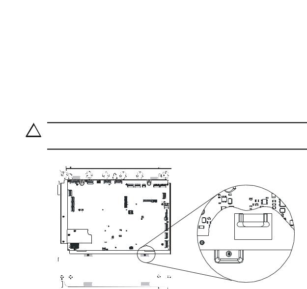
Backbox Installation |
Installation |
|
|
Mounting the Backbox
1.Mark and predrill hole in the wall for the center top keyhole mounting bolt using the dimensions illustrated in Figure 2.4 on page 28.
2.Install center top fastener in the wall with the screw head protruding.
3.Place backbox over the top screw, level and secure.
4.Mark and drill the left and right upper and lower mounting holes.
Note: Outer holes (closest to sidewall) are used for 16” O.C. stud mounting.
5.Install remaining fasteners and tighten.
6.Carefully reinstall the chassis assembly and dress panel by reversing the steps above. Use appropriate precautions to prevent damage to components due to static discharge. When reinstalling the chassis assembly, be sure that all four (4) tabs are seatedproperly in the slots of the backbox to avoid possible damage to the unit.
!CAUTION: POSSIBLE EQUIPMENT DAMAGE
REINSTALL THE CHASSIS ASSEMBLY CAREFULLY, MAKING SURE TO PROPERLY SEAT THE UNIT TO THE BACKBOX.
ECC-MCB-PCA |
Rev. |
Figure 2.3 Chassis Installation
7.Draw wires through the respective knockout locations.
An optional Trim Ring (P/N TR-CE) is available for semi-flush mount installations.
chassistab.wmf
Emergency Command Center Manual — P/N LS10001-000FL-E:A 4/10/2013 |
27 |

Installation |
Backbox Installation |
|
|
Hinge Slot for Dress Panel
Semi-Flush Mounting
Do not recess box more than 3.875” into wall to  avoid covering venting holes on top of box.
Mounting  slots for
 optional
 Trim Ring
Semi-flush mounting hole
Do not use these knock-outs! |
Hinge Slot for
Dress Panel
9050udencl.wmf
Figure 2.4 Cabinet Dimensions & Knockout Locations
28 |
Emergency Command Center Manual — P/N LS10001-000FL-E:A 4/10/2013 |

Backbox Installation |
Installation |
|
|
|
|
|
|
|
|
Top |
|
Depth |
|
|
|
|
|
|
|||
|
|
||||
|
|
|
|
|
|
|
|
|
|
|
|
|
Door |
|
|
|
Backbox |
|
|
ALL |
FIRE SYSTEM |
SYSTEM |
|
|
ACTIVE |
||
CALL |
|
|
CONTROL |
1 |
|
13 |
|
2 |
|
14 |
|
3 |
|
15 |
|
4 |
|
16 |
|
5 |
|
17 |
|
6 |
|
18 |
|
7 |
|
19 |
|
8 |
|
20 |
|
9 |
|
21 |
|
10 |
|
22 |
|
11 |
|
23 |
|
12 |
|
24 |
|
Door |
|
|
|
Backbox |
|
|
|
|
FI |
LIT ® AL |
|
|
by Honeywell |
|
|
Left Side
Bottom
Figure 2.5 ECC-50/100 Backbox Dimensions
Depth =
Right Side
ecc-cab.wmf
Emergency Command Center Manual — P/N LS10001-000FL-E:A 4/10/2013 |
29 |

Installation |
Operating Power |
|
|
2.3 Operating Power
WARNING: RISK OF EQUIPMENT DAMAGE AND PERSONAL INJURY
SEVERAL DIFFERENT SOURCES OF POWER CAN BE CONNECTED TO THIS PANEL. DISCONNECT ALL SOURCES OF POWER BEFORE SERVICING. THE PANEL AND ASSOCIATED EQUIPMENT MAY BE DAMAGED BY REMOVING AND/OR INSERTING CARDS, MODULES OR INTERCONNECTING CABLES WHILE THIS UNIT IS ENERGIZED. BE SURE TO OBSERVE PROPER GROUNDING AND HANDLING PROCEDURES.
2.3.1 AC Power and Earth Ground Connection
Primary power source for the ECC-50/100 is 120 VAC, 60 Hz, 3.5 amps. Primary power source for the ECC-50/100E is 240 VAC, 50 Hz, 2.0 amps. Over-current protection for this circuit must comply with Article 760 of the National Electrical Code (NEC) and/or local codes. Make certain that the AC mains circuit breaker is off before making any wiring connections between the mains and the panel. Connect AC mains wiring from the prot ected premises main breaker box to TB15 of the main control board. Use 14 AWG (2.0 mm2, 1.6 mm O.D.) or heavier gauge wire with 600V insulation. No other equipment may be connected to this circuit and it may not contain any power disconnect devices. A separate Earth Ground connection must be made to ensure proper panel operation and lightning and transient protection. Do not use conduit for the Earth Ground connection since this does not provide reliable protection. Remove the two keps nuts from the grounding stud in the backbox. Connect the incoming earth ground wire to supplied cable #71073 with a wire nut. Position the ring terminal end over the grounding stud. Secure with one of the keps nuts. Place the ring terminal from the other supplied cable to TB15. Refer to Figure 2.6 for the location of the stud. Apply AC power to the panel only after the system is completely installed and visually checked. Note that AC power must be applied to the panel before installing the battery interconnect cable (refer to the following section).
grounding stud
Grounding
Cable #71073
eccgnd.wmf |
Equipment
Ground
 keps nuts
grounding stud
Figure 2.6 Earth Ground Connection
30 |
Emergency Command Center Manual — P/N LS10001-000FL-E:A 4/10/2013 |
Loading...