


411UD

Digital Alarm
Communicator/Transmitter
411UD
Document #50759
11/07/2005 Rev.
P/N 50759:D ECN 05-465
© 2005
D

Fire Alarm System Limitations
While a fire alarm system may lower insurance
rates, it is not a substitute for fire insurance!
An automatic fire alarm system–typically made up of smoke
detectors, heat detectors, manual pull stations, audible warning devices, and a fire alarm control panel with remote notification capability–can provide early warning of a developing
fire. Such a system, however, does not assure protection
against property damage or loss of life resulting from a fire.
The Manufacturer recommends that smoke and/or heat detectors be located throughout a protected premise following
the recommendations of the current edition of the National
Fire Protection Association Standard 72 (NFPA 72),
manufacturer's recommendations, State and local codes, and
the recommendations contained in the Guide for Proper Use
of System Smoke Detectors, which is made available at no
charge to all installing dealers. A study by the Federal Emergency Management Agency (an agency of the United States
government) indicated that smoke detectors may not go off in
as many as 35% of all fires. While fire alarm systems are designed to provide early warning against fire, they do not guarantee warning or protection against fire. A fire alarm system
may not provide timely or adequate warning, or simply may not
function, for a variety of reasons:
Smoke detectors may not sense fire where smoke cannot
reach the detectors such as in chimneys, in or behind walls, on
roofs, or on the other side of closed doors. Smoke detectors
also may not sense a fire on another level or floor of a building. A second-floor detector, for example, may not sense a
first-floor or basement fire.
Particles of combustion or "smoke" from a developing fire
may not reach the sensing chambers of smoke detectors because:
• Barriers such as closed or partially closed doors, walls, or
chimneys may inhibit particle or smoke flow.
• Smoke particles may become "cold," stratify, and not reach
the ceiling or upper walls where detectors are located.
• Smoke particles may be blown away from detectors by air
outlets.
• Smoke particles may be drawn into air returns before reaching
the detector.
The amount of "smoke" present may be insufficient to alarm
smoke detectors. Smoke detectors are designed to alarm at
various levels of smoke density. If such density levels are not
created by a developing fire at the location of detectors, the
detectors will not go into alarm.
Smoke detectors, even when working properly, have sensing
limitations. Detectors that have photoelectronic sensing
chambers tend to detect smoldering fires better than flaming
fires, which have little visible smoke. Detectors that have ionizing-type sensing chambers tend to detect fast-flaming fires
better than smoldering fires. Because fires develop in different ways and are often unpredictable in their growth, neither
type of detector is necessarily best and a given type of detector may not provide adequate warning of a fire.
Smoke detectors cannot be expected to provide adequate
warning of fires caused by arson, children playing with
matches (especially in bedrooms), smoking in bed, and violent
explosions (caused by escaping gas, improper storage of
flammable materials, etc.).
Heat detectors do not sense particles of combustion and
alarm only when heat on their sensors increases at a predetermined rate or reaches a predetermined level. Rate-of-rise
heat detectors may be subject to reduced sensitivity over
time. For this reason, the rate-of-rise feature of each detector
should be tested at least once per year by a qualified fire protection specialist. Heat detectors are designed to protect
property, not life.
IMPORTANT! Smoke detectors must be installed in the
same room as the control panel and in rooms used by the
system for the connection of alarm transmission wiring, communications, signaling, and/or power. If detectors are not so
located, a developing fire may damage the alarm system,
crippling its ability to report a fire.
Audible warning devices such as bells may not alert people
if these devices are located on the other side of closed or
partly open doors or are located on another floor of a building.
Any warning device may fail to alert people with a disability or
those who have recently consumed drugs, alcohol or medication. Please note that:
• Strobes can, under certain circumstances, cause seizures
in people with conditions such as epilepsy.
• Studies have shown that certain people, even when they
hear a fire alarm signal, do not respond or comprehend the
meaning of the signal. It is the property owner's responsibility to conduct fire drills and other training exercise to
make people aware of fire alarm signals and instruct them
on the proper reaction to alarm signals.
• In rare instances, the sounding of a warning device can
cause temporary or permanent hearing loss.
A fire alarm system will not operate without any electrical
power. If AC power fails, the system will operate from standby
batteries only for a specified time and only if the batteries
have been properly maintained and replaced regularly.
Equipment used in the system may not be technically compatible with the control. It is essential to use only equipment
listed for service with your control panel.
Telephone lines needed to transmit alarm signals from a
premise to a central monitoring station may be out of service
or temporarily disabled. For added protection against telephone line failure, backup radio transmission systems are recommended.
The most common cause of fire alarm malfunction is inadequate maintenance. To keep the entire fire alarm system in
excellent working order, ongoing maintenance is required per
the manufacturer's recommendations, and UL and NFPA standards. At a minimum, the requirements of NFPA 72 shall be
followed. Environments with large amounts of dust, dirt or
high air velocity require more frequent maintenance. A maintenance agreement should be arranged through the local
manufacturer's representative. Maintenance should be
scheduled monthly or as required by National and/or local
fire codes and should be performed by authorized professional fire alarm installers only. Adequate written records of
all inspections should be kept.
PrecauLarge.PMD 01/10/2005

Installation Precautions
Adherence to the following will aid in problem-free
installation with long-term reliability:
WARNING - Several different sources of power can be con-
nected to the fire alarm control panel. Disconnect all sources
of power before servicing. Control unit and associated equipment may be damaged by removing and/or inserting cards,
modules, or interconnecting cables while the unit is energized.
Do not attempt to install, service, or operate this unit until this
manual is read and understood.
CAUTION - System Reacceptance Test after Software
Changes. To ensure proper system operation, this product
must be tested in accordance with NFPA 72 after any programming operation or change in site-specific software. Reacceptance testing is required after any change, addition or
deletion of system components, or after any modification,
repair or adjustment to system hardware or wiring.
All components, circuits, system operations, or software functions known to be affected by a change must be 100% tested.
In addition, to ensure that other operations are not inadvertently affected, at least 10% of initiating devices that are not
directly affected by the change, up to a maximum of 50 devices, must also be tested and proper system operation verified.
This system meets NFPA requirements for indoor dry operation at 0-49° C/32-120° F
RH (non-condensing) at 32 ±2° C/90 ±3° F. However, the
useful life of the system's standby batteries and the electronic components may be adversely affected by extreme
temperature ranges and humidity. Therefore, it is recommended that this system and all peripherals be installed in
an environment with a nominal room temperature of 15-27°
C/60-80° F.
Verify that wire sizes are adequate for all initiating and
indicating device loops. Refer to manual Specifications section for maximum allowable I.R. drop from the specified device voltage.
and at a relative humidity of 93 ±2%
Like all solid state electronic devices, this system may
operate erratically or can be damaged when subjected to
lightning-induced transients. Although no system is completely immune from lightning transients and interferences,
proper grounding will reduce susceptibility. Overhead or out-
side aerial wiring is not recommended, due to an increased
susceptibility to nearby lightning strikes. Consult with the
Technical Services Department if any problems are anticipated or encountered.
Disconnect AC power and batteries prior to removing or inserting circuit boards. Failure to do so can damage circuits.
Remove all electronic assemblies prior to any drilling, filing,
reaming, or punching of the enclosure. When possible, make
all cable entries from the sides or rear. Before making modifications, verify that they will not interfere with battery, transformer, and printed circuit board location.
Do not tighten screw terminals more than 9 in-lbs.
Over-tightening may damage threads, resulting in reduced
terminal contact pressure and difficulty with screw terminal
removal.
This system contains static-sensitive components.
Always ground yourself with a proper wrist strap before handling any circuits so that static charges are removed from the
body. Use static-suppressive packaging to protect electronic
assemblies removed from the unit.
Follow the instructions in the installation, operating, and
programming manuals. These instructions must be followed
to avoid damage to the control panel and associated
equipment. FACP operation and reliability depend upon
proper installation by authorized personnel.
FCC Warning
WARNING: This equipment generates, uses, and can ra-
diate radio frequency energy and if not installed and used
in accordance with the instruction manual, may cause interference to radio communications. It has been tested
and found to comply with the limits for class A computing
device pursuant to Subpart B of Part 15 of FCC Rules,
which is designed to provide reasonable protection against
such interference when operated in a commercial environment. Operation of this equipment in a residential area is
likely to cause interference, in which case the user will be
required to correct the interference at their own
expense.
PrecauLarge.PMD 01/10/2005
Canadian Requirements
This digital apparatus does not exceed the Class A
limits for radiation noise emissions from digital
apparatus set out in the Radio Interference Regulations
of the Canadian Department of Communications.
Le present appareil numerique n'emet pas de bruits
radioelectriques depassant les limites applicables aux
appareils numeriques de la classe A prescrites dans le
Reglement sur le brouillage radioelectrique edicte par le
ministere des Communications du Canada.

Notes
4 411UD Document #50759 Rev. D 11/07/2005 P/N 50759:D

Table of Contents
CHAPTER 1: Product Description .........................................................................................................................8
1.1: Product Features..........................................................................................................................................8
FIGURE 1-1: 411UD Digital Communicator......................................................................................8
1.2: Specifications ..............................................................................................................................................9
1.3: Circuits ........................................................................................................................................................10
1.3.1: Power Requirements .........................................................................................................................10
1.3.2: Channels/Inputs.................................................................................................................................10
1.3.3: Primary and Secondary Phone Lines ................................................................................................10
1.3.4: Earth Ground.....................................................................................................................................10
1.4: Controls and Indicators ...............................................................................................................................11
FIGURE 1-2: 411UD Controls and Indicators ....................................................................................11
1.5: Digital Communicator Operation................................................................................................................12
1.6: Telephone Requirements and Warnings ......................................................................................................12
1.6.1: Telephone Circuitry - PH1 & PH2....................................................................................................12
1.6.2: Digital Communicator: .....................................................................................................................12
1.6.3: Telephone Company Rights and Warnings:......................................................................................13
1.6.4: For Canadian Applications................................................................................................................13
1.7: Operational Modes ......................................................................................................................................14
1.7.1: Normal Mode ....................................................................................................................................14
1.7.2: Real Time Clock Mode.....................................................................................................................14
1.7.3: Program Mode...................................................................................................................................14
1.7.4: Troubleshoot Mode...........................................................................................................................14
1.7.5: Default Mode ....................................................................................................................................14
CHAPTER 2: Installation.........................................................................................................................................15
2.1: Mounting Options .......................................................................................................................................15
FIGURE 2-1: 411UD Enclosure..........................................................................................................15
2.2: Operating Power..........................................................................................................................................15
2.3: Input Channels.............................................................................................................................................15
FIGURE 2-2: Typical FACP Connection to 411UD ...........................................................................16
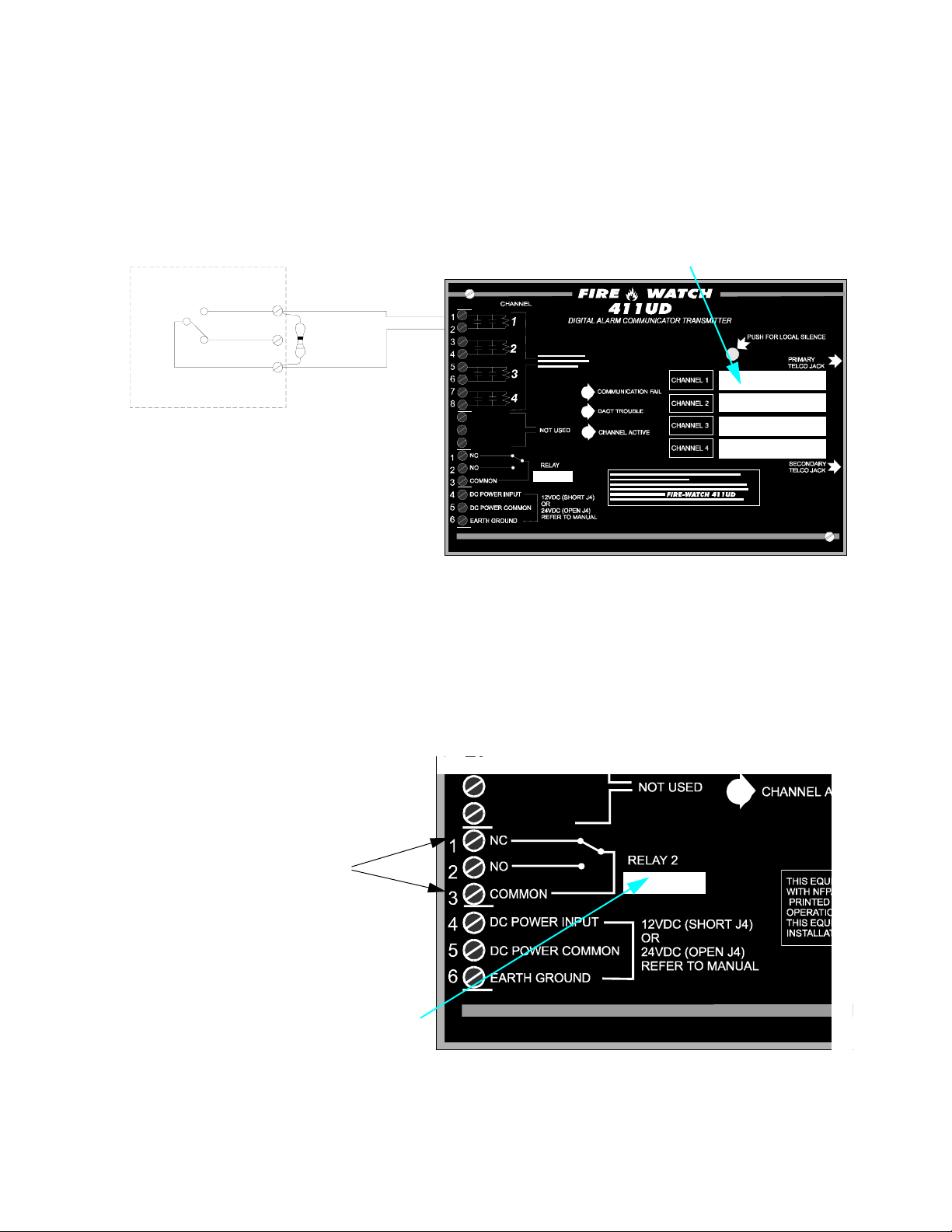
FIGURE 2-3: Style B Channel Connections........................................................................................17
2.4: Output Circuits ............................................................................................................................................17
FIGURE 2-4: Programmable Relay.....................................................................................................17
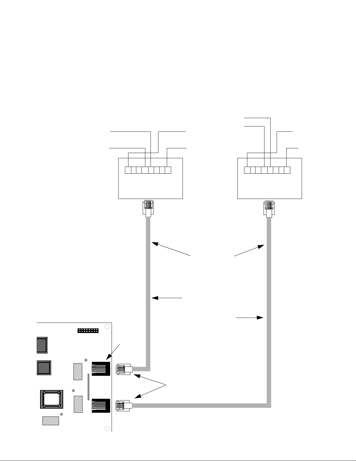
2.5: Telephone Circuits.......................................................................................................................................18
FIGURE 2-5: Wiring Phone Jacks.......................................................................................................18
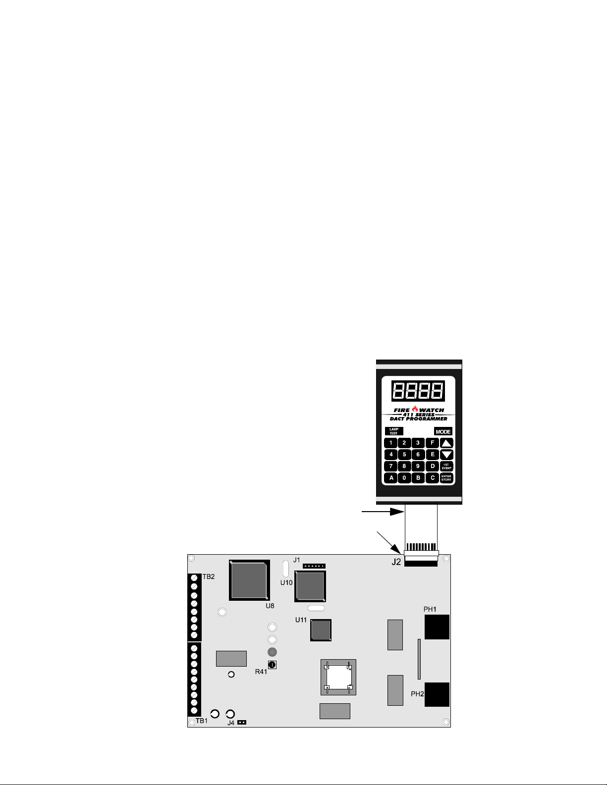
2.6: Optional Programmer..................................................................................................................................19
FIGURE 2-6: Programmer Connection to 411UD ..............................................................................19
2.7: UL Power-limited Wiring Requirements ....................................................................................................20
CHAPTER 3: Modes of Operation..........................................................................................................................21
3.1: Normal Mode ..............................................................................................................................................21
3.1.1: Programmer Key Functions ..............................................................................................................22
FIGURE 3-1: Programmer Keypad .....................................................................................................22
3.1.2: Programmer Display .........................................................................................................................23
3.2: Real Time Clock Mode ...............................................................................................................................23
3.3: Program Mode ............................................................................................................................................25
3.3.1: DACT Programming.........................................................................................................................26
TABLE 3-1: Ademco Contact ID Format - Primary ...........................................................................28
TABLE 3-2: 4+2 Standard and 4+2 Express Formats - Primary.........................................................28
TABLE 3-3: All 3+1, 4+1 and 4+2 Expanded Formats - Primary ......................................................29
TABLE 3-4: Ademco Contact ID Format - Secondary .......................................................................32
TABLE 3-5: 4+2 Standard and 4+2 Express Formats - Secondary.....................................................32
411UD Document #50759 Rev. D 11/07/2005 P/N 50759:D 5

Table of Contents
TABLE 3-6: All 3+1, 4+1 and 4+2 Expanded Formats - Secondary ..................................................33
3.4: Default Mode...............................................................................................................................................38
3.5: Troubleshoot Mode......................................................................................................................................38
FIGURE 3-2: Handset/Speaker Connection ........................................................................................39
CHAPTER 4: Central Station Communications ....................................................................................................40
TABLE 4-1: Format Selection Addresses ( 20 and 50) Programming ................................................41
TABLE 4-2: Format Selection Address Explanation...........................................................................42
4.0.1: Transmittal Priorities.........................................................................................................................43
4.0.2: Ademco Contact ID Format Event Code Description.......................................................................44
TABLE 4-3: Compatible UL Listed Receivers....................................................................................45
CHAPTER 5: Remote Site Upload/Download........................................................................................................46
5.1: General ........................................................................................................................................................46
5.1.1: Security Features...............................................................................................................................47
5.2: Downloading to the Communicator ............................................................................................................48
5.3: Uploading From the Communicator............................................................................................................48
5.4: Simultaneous Data Transfers.......................................................................................................................49
Appendix A: Programming Sheets .......................................................................................................................50
A.1: Digital Communicator Options Program Sheets .......................................................................................50
A.2: Digital Communicator Options Program Sheet (Factory Defaults) ..........................................................52
Appendix B: Event Codes/Transmission Format Programming Sheets ..........................................................54
B.1: 4+2 Standard & 4+2 Express Formats Primary
B.2: 4+2 Standard & 4+2 Express Formats Secondary
B.3: 4+2 Standard & 4+2 Express Formats Primary
B.4: 4+2 Standard & 4+2 Express Formats Secondary
B.5: All 3+1, All 4+1 and 4+2 Expanded Formats for Primary
B.6: All 3+1, All 4+1 and 4+2 Expanded Formats for Secondary
B.7: All 3+1, All 4+1 and 4+2 Expanded Formats for Primary
B.8: All 3+1, All 4+1 and 4+2 Expanded Formats for Secondary
B.9: Ademco Contact ID Format Primary
Central Station ................................................................................57
B.10: Ademco Contact ID Format Secondary
B.11: Ademco Contact ID Format Primary
Central Station (Factory Defaults) ...............................................57
B.12: Ademco Contact ID Format Secondary
Central Station ................................................................54
Central Station ............................................................54
Central Station ................................................................55
Central Station ............................................................55
Central Station ...............................................56
Central Station ...........................................56
Central Station (Factory Defaults) ................56
Central Station (Factory Defaults) ...........56
Central Station ..........................................................................57
Central Station (Factory Defaults) ...........................................57
Appendix C: Ademco Contact ID Format Event Code Description .................................................................58
Appendix D: Wire Requirements .........................................................................................................................62
TABLE 5-1: Wire Specifications.........................................................................................................62
Appendix E: Operational Modes ..........................................................................................................................63
TABLE 5-2: Operational Modes..........................................................................................................63
6
411UD Document #50759 Rev. D 11/07/2005 P/N 50759:D

This digital communicator has been designed to comply with standards set forth by the following regulatory agencies:
• Underwriters Laboratories Standard
• NFPA 72 National Fire Alarm Code
• CAN/ULC - S527-M87 Standard for Control Units for Fire Alarm Systems
Before proceeding, the installer should be familiar with the following documents.
NFPA Standards
This digital communicator complies with the NFPA 72 National Fire Alarm Code for:
Central Station Signaling Systems Protected Premises Unit (Automatic, Manual and Waterflow)
Local Fire Alarm Systems (Automatic, Manual, Waterflow and Sprinkler Supervisory)
Proprietary Fire Alarm Systems (Protected Premises Unit)
Remote Station Fire Alarm Systems
Automatic Fire Detectors
Installation, Maintenance and Use of Notification Appliances for Fire Alarm Systems
Inspection, Testing and Maintenance for Fire Alarm Systems
Underwriters Laboratories Documents:
UL 217 Smoke Detectors, Single and Multiple Station
UL 268 Smoke Detectors for Fire Protective Signaling Systems
UL 346 Waterflow Indicators for Fire Protective Signaling Systems
UL 464 Audible Signaling Appliances
UL 521 Heat Detectors for Fire Protective Signaling Systems
UL 864 Standard for Control Units for Fire Protective Signaling Systems
UL 1076 Proprietary Burglar Alarm Units and Systems
UL 1481 Power Supplies for Fire Protective Signaling Systems
UL 1635 Digital Alarm Communicator System Units
UL 1638 Visual Signaling Appliances
UL 1971 Signaling Devices for Hearing Impaired
CAN/ULC - S524-M91 Standard for Installation of Fire Alarm Systems
Other:
NEC Article 250 Grounding
NEC Article 300 Wiring Methods
NEC Article 760 Fire Protective Signaling Systems
Applicable Local and State Building Codes
Requirements of the Local Authority Having Jurisdiction (LAHJ)
This product has been certified to comply with the requirements in the Standard for Control Units and Accessories for Fire Alarm Systems, UL
864, 9th Edition. Operation of this product with products not tested for UL 864, 9th Edition has not been evaluated. Such operation requires the
approval of the local Authority Having Jurisdiction (AHJ).
411UD Document #50759 Rev. D 11/07/2005 P/N 50759:D 7
Product Description
CHAPTER 1 Product Description
The 411UD is a four input/channel, dual line, digital communicator which can be used as a slave communicator with
UL listed fire and nonfire control panels. The four inputs are compatible with normally open relay contacts, require
End-Of-Line (EOL) resistors, are supervised and are fully programmable. The 411UD interfaces with the public
switched telephone network and is compatible with most central station receivers. A total of fifteen popular communications formats are supported, including Ademco Contact ID. The communicator also contains a unique DACT
option that eliminates 'dialer runaway'. It restricts the transmission of any trouble event to 10 attempts in a 24 hour
period. Power supplied must be 12 or 24 volts, filtered and nonresettable. Accessories include the Fire-Watch 411
Series DACT Programmer (Model PRO-411) as well as the PK-411 Windows
software. The 411UD comes in a small 6.841" (17.376 cm) X 4.595" (11.671 cm) X 1.00" (2.54 cm) metal enclosure,
providing a variety of mounting options.
®
95 based remote site programming
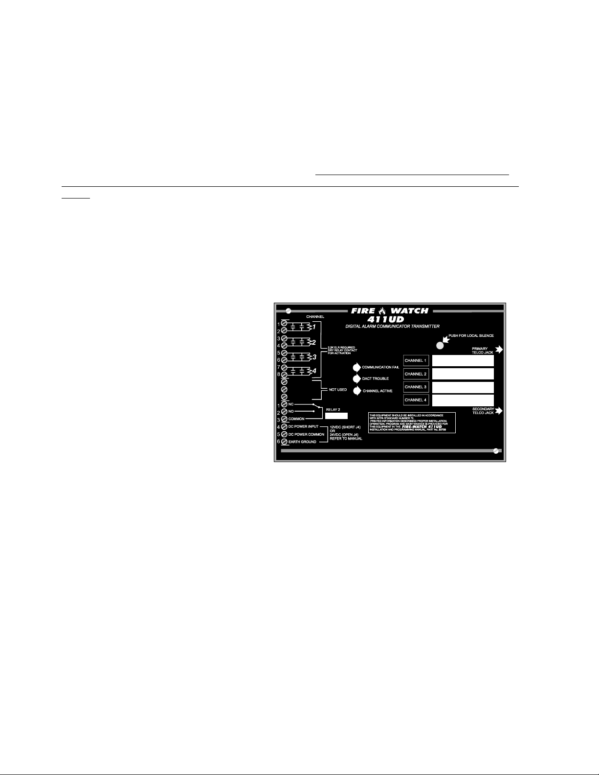
1.1 Product Features
FIGURE 1-1:411UD Digital Communicator
• Four input channels
• Dual telephone lines
Dual telephone line voltage detect
Alternating phone lines for 24 hour
test messages
• Program locations for entering up to 20-digit
central station and service terminal
telephone numbers
• Surface mount technology
• Compact in size
• Separate external keypad and display
provides means of programming digi-
tal communicator in program mode
provides means of testing phone circuits in troubleshoot mode
• 6.841" (17/376 cm) X 4.595" (11.671 cm) X 1.0" (2.54 cm) metal enclosure facilitates internal and external
control panel mounting
• Communicates vital status of monitored control panel:
fire alarm
host control panel trouble
fire supervisory
AC (mains) power loss (programmable)
other
• Communicates vital status of 411UD digital communicator:
digital communicator troubles
telephone Line 1 and 2 voltage fault
Primary Central Station number communication fault
Secondary Central Station number communication fault
system off-normal (local Program Mode entered)
24 Hour normal test
24 Hour abnormal test (24 hour test message with previously reported alarm or trouble still active)
411udcvr.cdr
8
411UD Document #50759 Rev. D 11/07/2005 P/N 50759:D

Specifications
• Individual LEDs for:
Communication Fail (visible with cover on)
DACT Trouble (visible with cover on)
Channel Active (visible with cover on)
Primary Phone Line (PH1) active
Secondary Phone Line (PH2) active
Modem Active
• Piezo sounder
• Local piezo silence switch which silences onboard piezo sounder (accessible without removing cover)
• Real time clock
• Extensive transient protection
• One Form-C relay, fully programmable to activate for the following conditions:
fire alarm
host control panel trouble
fire supervisory
total communication failure
AC loss
DACT trouble (factory default for relay)
• PK-411 Remote Upload/Download Kit
• Industry-first, UL recognized 'dialer runaway' feature'
• Trouble Resound - if a trouble is silenced and the cause of the trouble is not cleared, the panel will resound
the trouble buzzer every midnight, until the trouble is cleared.
1.2 Specifications
Operating Power
The 411UD may be powered from UL listed control panels that output nonresettable and power-limited 12 or 24
VDC power. The configuration of Jumper J4 determines whether 12 VDC power is to be supplied directly to the
411UD circuit board or 24 VDC power is to be supplied and then internally regulated down internally to 12 VDC.
DC Power - TB1 Terminals 4(+) and 5(-), Terminal 6 is Earth Ground
• J4 Jumper removed - Filtered, nonresettable and power-limited 24 VDC (nominal) power must be supplied at
TB1 Terminals 4(+) and 5(-). Operating voltage provided must be within 21.3 to 24.0 VDC (UL tested range:
1
-15%, +10%). Current requirements are 100 mA in standby and 170 mA
• J4 Jumper installed - Filtered, nonresettable and power-limited 12 VDC (nominal) power must be supplied at
TB1 Terminals 4(+) and 5(-). Operating voltage provided must be within 11.2 to 12.4 VDC (UL tested range:
-15%, +10%). Current requirements are 100 mA in standby and 170 mA
while communicating.
1
while communicating.
1. A maximum of 300 mA is possible with all input channels shorted, the 411UD communicating, the Programmer connected and
Lamp Test active.
411UD Document #50759 Rev. D 11/07/2005 P/N 50759:D 9

Circuits
Channels/Inputs1 - TB2 Terminals 1 through 8
Programmable Channels 1 through 4
Power-limited circuitry
Fully supervised
Operation: All channels NFPA Style B (Class B). Requires Normally Open contact to trigger
Normal Operating Voltage: 12 VDC
Maximum Line Resistance: 100 ohms per channel
Alarm Current: 3.34 mA
End-Of-Line Resistor: 2.2K ohms, ½ watt (P/N 27070)
Short Circuit Current: 3.8 mA per channel/input
One Form-C Relay - TB1 Terminals 1 through 3
Contact rating: 2.0 amps @ 30 VDC (resistive)
1.3 Circuits
The 411UD circuit board utilizes surface mount technology and contains a MicroController Unit (MCU), dual modular phone line jacks, piezo sounder, piezo silence switch, one programmable relay and two connectors for input, output and power wiring.
1.3.1 Power Requirements
Voltage for the digital communicator may be a power-limited, filtered, nonresettable nominal 12 VDC [11.2 to
12.4 VDC (UL tested range: -15%, +10%)] or nominal 24 VDC [21.3 to 24.0 VDC (UL tested range: -15%,
+10%)]. Jumper J4 is used to select the power source.
1.3.2 Channels/Inputs
Four input channels are provided on the 411UD digital communicator which are used for connection to the control
panel being monitored. Each input can be programmed to monitor the control panel for:
• fire alarm activation
• trouble activation
• fire supervisory activation
• AC loss activation
Each input channel is configured as a Class B circuit and must be wired to a Normally Open contact.
1.3.3 Primary and Secondary Phone Lines
Modular jacks are used to interface the primary and secondary phone lines to the public telephone network.
1.3.4 Earth Ground
Connect a separate earth ground wire to TB1 terminal 6 for transient protection.
Note: If zero ohms impedance exists between the 411UD circuitry and earth ground, a ground fault will be indicated at the host FACP.
1. Channels/inputs do not support 2-wire smoke detectors.
10
411UD Document #50759 Rev. D 11/07/2005 P/N 50759:D
Controls and Indicators
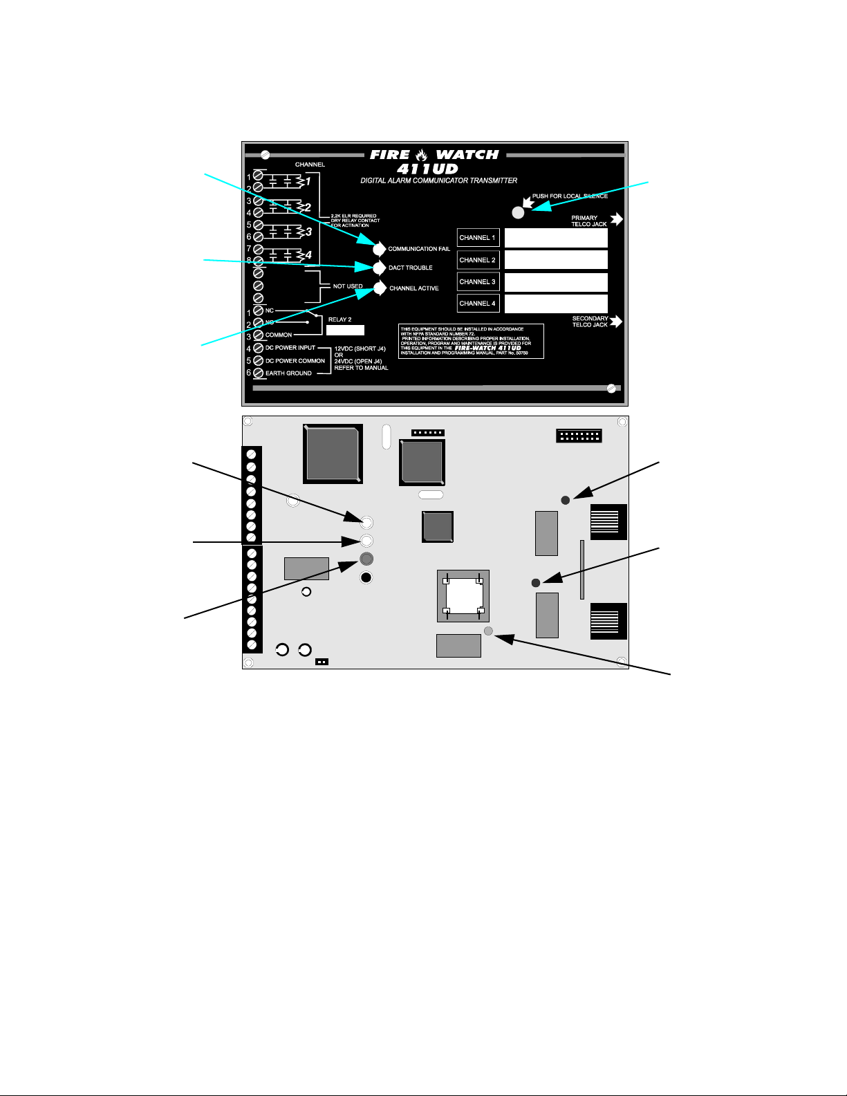
1.4 Controls and Indicators
FIGURE 1-2:411UD Controls and Indicators
Comm.
Fail LED
DACT
Trouble
LED
Piezo
Silence
Switch
Channel
Active
LED
J1
Comm.
Fail LED
TB2
U10
U8
U11
DACT
Trouble
LED
R41
Channel
Active
LED
TB1
J4
Front Panel Switch
• Silence Switch - press to silence local 411UD piezo sounder
411udcvr.cdr
J2
PH1 LED
PH1
PH2 LED
411udbrd.cdr
PH2
Modem
LED
411UD Piezo Sounder
• The 411UD piezo sounder is used to locally annunciate DACT troubles. DACT troubles include input channel open circuit, phone line 1 or 2 voltage fault, phone number 1 or 2 communication fault, total communication failure and communications disabled.
Front Panel Indicators
• Communication Fail - yellow LED
• DACT Trouble - yellow LED
• Channel Active - red LED
Circuit Board Indicators
• Primary Phone Line 1 (PH1) Active - red LED
• Secondary Phone Line 2 (PH2) Active - red LED
• Modem Active - green LED
411UD Document #50759 Rev. D 11/07/2005 P/N 50759:D 11

Digital Communicator Operation
1.5 Digital Communicator Operation
The 411UD has been designed to be compatible with a wide variety of fire alarm, nonfire and combination control
panels. Numerous formats are also available for communication to a central station. Two modular phone jacks allow
easy connection to telephone lines. Modular jacks are labeled PH1 and PH2 for the Primary and Secondary phone
lines. The digital communicator provides the following functions:
• Line Seizure- takes control of the phone lines, disconnecting any premises phones using the same lines
• Off/On-Hook - perform on and off-hook status to phone lines
• Listen for dial tone - 440 hertz tone typical in most networks
• Dialing the Central Station(s) phone number - default is Touch-Tone®, programmable to rotary
• Discern proper Central Station 'ACK' and 'Kiss-off' tone(s)
• Transmit data to the Central Station(s)
• Verify data has been accepted by the Central Station(s)
• Hang-up and release phone lines
• Communicate in a variety of formats (Refer to Table 4-1, “Format Selection Addresses ( 20 and 50) Programming,” on page 41).
1.6 Telephone Requirements and Warnings
1.6.1 Telephone Circuitry - PH1 & PH2
AC Ringer Equivalence Number (REN) = 0.5B
DC Ringer Equivalence Number (REN) = 1.3
Complies with FCC Part 68
Mates with RJ31X Male Connector
Supervision Threshold: less than 4.0 volts for 2 minutes
The REN is used to determine the quantity of devices which may be connected to the telephone line. Excessive
RENs on the telephone line may result in the devices not ringing in response to an incoming call. In most, but not all
areas, the sum of the RENs should not exceed five (5.0). To be certain of the number of devices that may be connected to the line, as determined by the total RENs, contact the telephone company to determine the maximum REN
for the calling area.
1.6.2 Digital Communicator:
Before connecting the 411UD to the public switched telephone network, the installation of two RJ31X jacks is necessary. The following information is provided if required by the local telephone company:
Manufacturer: Fire•Lite Alarms Inc./Notifier
One Fire-Lite Place
Northford, CT 06472
Product Model Number: 411UD
FCC Registration Number: OAAUSA-25431-AL-E
Ringer Equivalence 0.5B
Note: FCC ID label is located on the inside cover.
Important! The DACT must not
9th Edition.
12
be used to dial a phone number that is call-forwarded per requirements of UL 864
411UD Document #50759 Rev. D 11/07/2005 P/N 50759:D

Telephone Requirements and Warnings
1.6.3 Telephone Company Rights and Warnings:
The telephone company, under certain circumstances, may temporarily discontinue services and/or make changes in
its facilities, services, equipment or procedures which may affect the operation of this digital communicator. However, the telephone company is required to give advance notice of such changes or interruptions. If the digital communicator causes harm to the telephone network, the telephone company reserves the right to temporarily
discontinue service. Advance notification will be provided except in cases when advance notice is not practical. In
such cases, notification will be provided as soon as possible. The opportunity will be given to correct any problems
and to file a complaint.
DO NOT CONNECT THIS PRODUCT TO COIN TELEPHONE, GROUND START OR PARTY LINE SERVICES.
When the digital communicator activates, premise phones will be disconnected.
Two separate phone lines are required. Do not connect both telephone interfaces to the same telephone line.
The digital communicator must be connected to the public switched telephone network upstream of any private telephone system at the protected premises.
An FCC compliant telephone cord must be used with this equipment. This equipment is designed to be connected to
the telephone network or premises wiring using a compatible RJ31X male modular plug which is Part 68 compliant.
1.6.4 For Canadian Applications
The following is excerpted from CP-01 Issue 5:
“NOTICE: The Industry Canada (IC) label identifies certified equipment. This certification means that the equipment meets certain telecommunications network protective, operational and safety requirements as prescribed in the
appropriate Terminal Equipment Technical Requirements document(s). The Department does not guarantee the
equipment will operate to the user’s satisfaction.”
Before installing this equipment, users should ensure that it is permissible to be connected to the facilities of the local
telecommunications company. The equipment must also be installed using an acceptable method of connection. The
customer should be aware that compliance with the above conditions may not prevent degradation of service in some
situations.
Repairs to certified equipment should be made by an authorized Canadian maintenance facility designated by the
supplier. Any repairs or alterations made by the user to this equipment, or equipment malfunctions, may give the
telecommunications company cause to request the user to disconnect the equipment.
Users should ensure for their own protection that the electrical ground connections of the power utility, telephone
lines and internal metallic water pipe system, if present, are connected together. This precaution may be particularly
important in rural areas.
CAUTION
Users should not attempt to make such connections themselves, but should contact the appropriate electric inspection
authority, or electrician.
“The Ringer Equivalence Number
number of terminals allowed to be connected to a telephone interface. The termination of an interface may consist of
any combination of devices subject only to the requirement that the sum of the REN of all devices does not exceed 5.”
(REN) assigned to each terminal device provides an indication of the maximum
Representative: NOTIFIER, CANADA
IC Certificate Number: 2132 9028 A
Ringer Equivalence Number (REN): 0.2
411UD Document #50759 Rev. D 11/07/2005 P/N 50759:D 13
10 Whitmore Road
Woodbridge, Ontario L4L 7Z4

Operational Modes
1.7 Operational Modes
1.7.1 Normal Mode
Normal Mode is the standard mode of operation in which the 411UD digital communicator monitors the host control
panel status as well as telephone line voltage and other internal circuits. In addition to locally annunciating system
trouble, active channel and communication fail, the digital communicator transmits system status information to UL
listed central station receivers. Transmitted data includes fire alarm, fire alarm trouble, supervisory alarm and AC
loss information. Specific digital communicator troubles are also transmitted.
1.7.2 Real Time Clock Mode
Real Time Clock Mode allows the user to change the digital communicator’s internal 24 hour clock. Connecting an
external Programmer allows access to the various Modes of operation. While the communicator is in Real Time
Clock Mode, it does not monitor channel inputs.
1.7.3 Program Mode
Program Mode is used to change the programmed functions of the 411UD digital communicator. While the communicator is in Program Mode, it does not monitor channel inputs.
1.7.4 Troubleshoot Mode
Troubleshoot Mode may be used for testing the telephone line interconnect wiring. Connection from the 411UD’s
modular jacks, through the RJ31X jacks and into the telephone network may be easily checked. In this mode, the
Programmer keypad acts similar to a telephone touchpad. While the communicator is in Troubleshoot Mode, it does
not monitor channel inputs.
1.7.5 Default Mode
Default Mode may be used to return all 411UD programming back to the factory default settings.
14
411UD Document #50759 Rev. D 11/07/2005 P/N 50759:D
Installation
CHAPTER 2 Installation
2.1 Mounting Options
The 411UD with enclosure may be mounted in the cabinet of the Fire•Lite/Notifier control panel which is being monitored or in any enclosure UL listed for fire protective use. When using with other than Fire•Lite/Notifier control
panels, the 411UD may be mounted in any enclosure UL listed for fire protective use. Mounting tabs are provided
for ease of mounting.
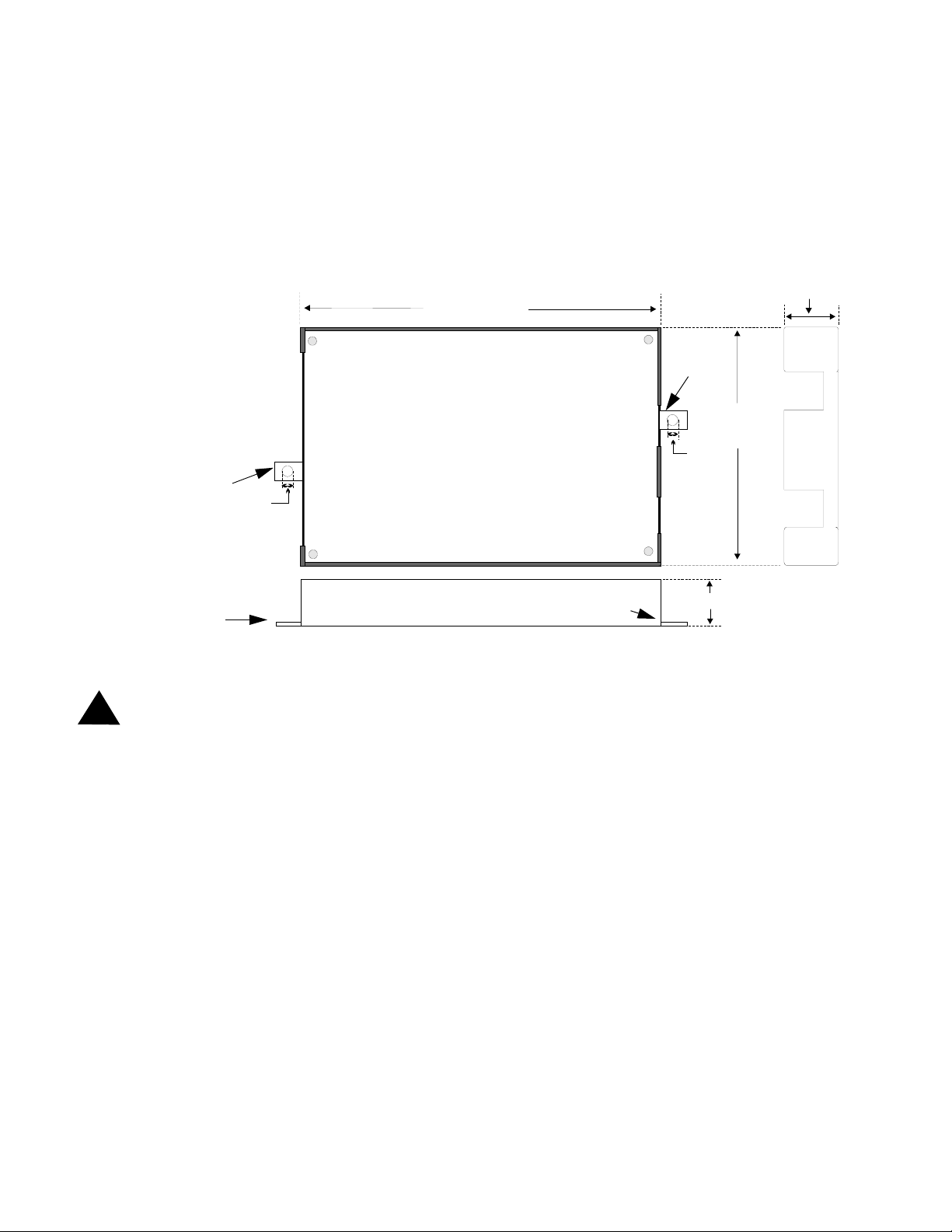
FIGURE 2-1:411UD Enclosure
Mounting bracket
0.187“
(0.475 cm)
6.841“ (17.376 cm)
Mounting
bracket
0.187“
(0.475 cm)
4.595“
(11.671 cm)
1.000“
(2.54 cm)
Mounting bracket
Bottom
Mounting bracket
1.000“ (2.54 cm)
2.2 Operating Power
CAUTION: Disconnect all power before servicing the 411UD. The digital communicator may be damaged by
!
removing and/or inserting components or interconnecting cables while the unit is energized.
12VDC or 24VDC nominal power connections are made to TB1 on the 411UD circuit board. When jumper J4 is
installed, the 11.2 to 12.4 VDC nominal operating voltage (UL tested range: -15%, +10%) for the digital communicator must be power-limited, filtered, nonresettable. This 12 VDC nominal operating power can be supplied directly to
the 411UD by a UL listed 12 VDC power supply listed for fire protection or by a nonresettable 12 VDC output from
a control panel. Alternatively, removing J4 Jumper on the digital communicator circuit board allows the 411UD to be
supplied by a power-limited, nonresettable 21.3 to 24.0 VDC (UL tested range: -15%, +10%). This 24 VDC nominal
operating power can be supplied by a UL listed 24 VDC power supply, which, in order to comply with UL 864 must
be listed for Fire Protective Signaling Systems or by a nonresettable 24 VDC output from a control panel. This nominal 24 VDC power is then internally regulated by the digital communicator to 12 VDC operating power.
Note that upon power-up, the 411UD will immediately annunciate a DACT trouble since the communicator is factory
defaulted to 'communicator disabled' at program location 64.
411bkbox.cdr
2.3 Input Channels
The 411UD digital communicator has four channel inputs. Each channel is supervised for opens (trouble) and shorts
(alarm) by the digital communicator. Each channel is a Style B (Class B) Initiating Device Circuit designed to accept
any normally-open contact device. Since channels do not latch, a reset switch is not provided by the 411UD. The
communicator transmissions to a central station track the state of the inputs. Refer to Figure 2-3, “Style B Channel
Connections,” on page 17 for information on wiring Style B circuits.
411UD Document #50759 Rev. D 11/07/2005 P/N 50759:D 15
Input Channels
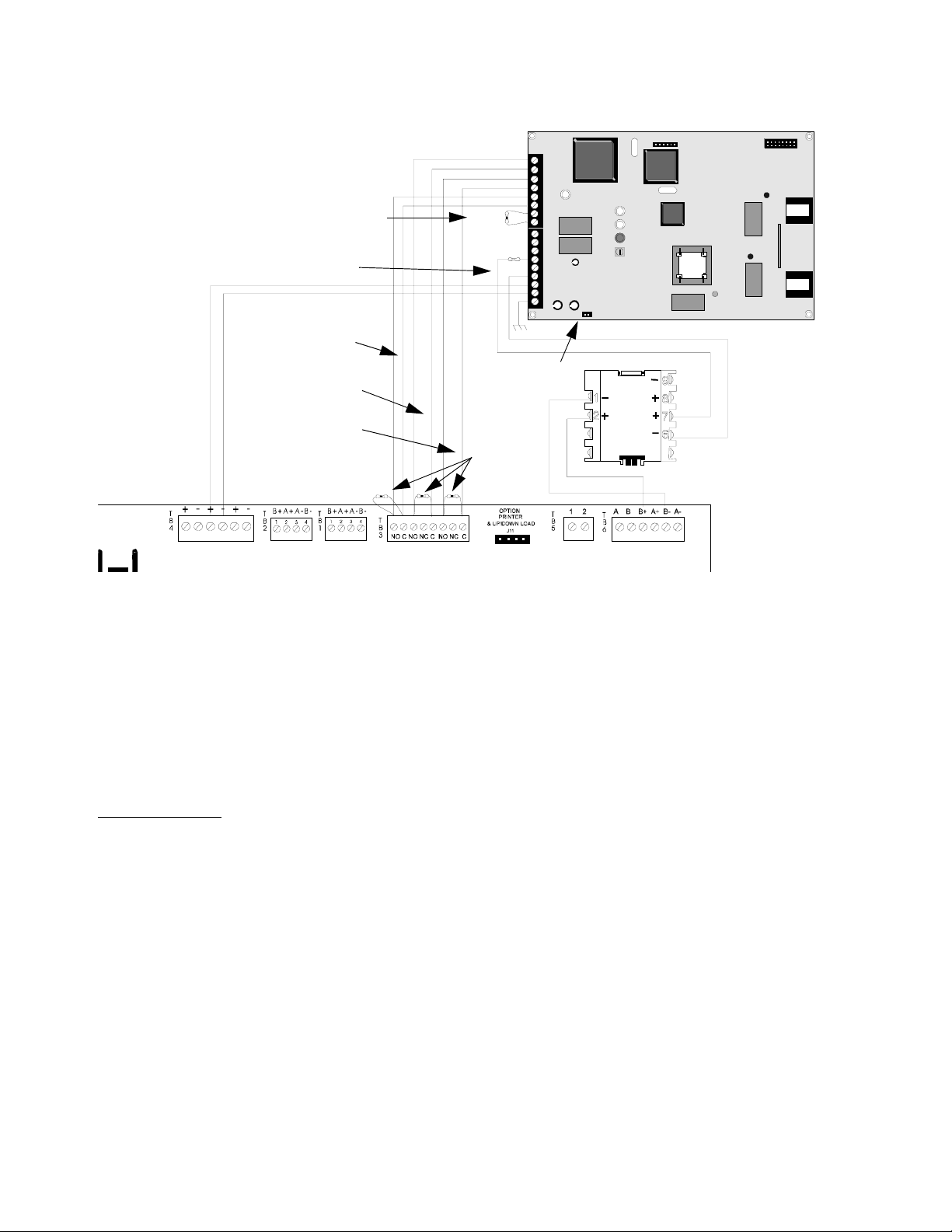
FIGURE 2-2:Typical FACP Connection to 411UD
Note: The monitor module input,
which is being used to monitor the
411UD Relay Output (programmed
for DACT Trouble), must be pro-
Channel 4
grammed as 'DACT Trouble' at the
FACP
Relay Output
(DACT Trouble)
24 VDC nonresettable power
Supervisory
Relay
Alarm Relay
Trouble
Relay
+ -
Channel 1
Channel 2
Channel 3
2.2K
EOL
47K EOL
J4 Not Installed
2.2K EOLS
P/N 27070
TB2
TB1
J4
SLC Loop
U8
R41
M300
J1
U10
U11
Monitor Module
J2
PH1
PH2
411UD
Circuit Input
9200411u.cdr
Addressable FACP
Each input channel monitors a normally open device and may be programmed as follows:
• fire alarm
• host control panel trouble
• fire supervisory
•AC Loss
Programming the input channel automatically programs the transmitted event code, however, the event code can be
changed since it is fully programmable. Event code transmissions can be tailored to the specific application and
requirements of the Central Station.
AC Loss Reporting:
Channel 4, which is defaulted to AC Loss, will transmit a specific AC loss signal only if the
assigned Normally Open contact provides this function. Some panels provide an option that will automatically delay
the trigger of their system trouble relays upon loss of AC. If this is provided by the host panel, use Channel 2. Be certain to verify the method employed by the host panel to be monitored.
The factory default programming for each channel is as follows:
Channel 1 - fire alarm
Channel 2 - host control panel trouble
Channel 3 - fire supervisory
Channel 4 - AC Loss
16
411UD Document #50759 Rev. D 11/07/2005 P/N 50759:D
Output Circuits
Channel Labels
Note that space is provided for labeling the function of each channel. Write the function that has been programmed
for each channel in the white boxes located to the right of the channel designator.
FIGURE 2-3:Style B Channel Connections
Inputs are supervised,
power-limited
2.2K EOL Resistor
P/N 27070
Normally Open Contact Device
2.4 Output Circuits
411udchl.cdr
Channel/Input Labels
Relays
The 411UD provides one Form-C relay rated for 2.0 amps @ 30 VDC (resistive). The relay is programmable for
activation on fire alarm, host panel trouble, fire supervisory, total communication failure, AC loss and DACT
trouble.
FIGURE 2-4:Programmable Relay
One Form-C Relay
(nonsupervised)
Relay Label
Relay Label
Note that space is provided for labeling the function of the relay. Write the function that has been programmed for the
relay in the white box located below the relay designator.
411udcvr.cdr
411UD Document #50759 Rev. D 11/07/2005 P/N 50759:D 17
Telephone Circuits
2.5 Telephone Circuits
Provision to connect two independent telephone lines is available via two telephone jacks labeled PH1 (Primary)
and PH2 (Secondary). Telephone line control/command is possible via double line seizure as well as usage of an
RJ31X style interconnection. (RJ31X jacks must be ordered separately).
CAUTION: It is critical that the 411UD be located as the first device on the incoming telephone circuit to
properly function.
FIGURE 2-5:Wiring Phone Jacks
Tip
Ring
Green Wire
Red Wire
(Primary Lines)
Incoming Telco
Phone Lines
Ring
To Premises Phone
Tip
1 2 3 4 5 6 7 8 1 2 3 4 5 6 7 8
(Secondary Lines)
Green Wire
Tip
Red Wire
Ring
Incoming Telco
Phone Lines
To Premises
Ring
Phone
Tip
411UD
J2
Modular
Female
Connector
RJ31X
JACK
Note: Shorting bars
inside RJ31X Jack
removed during
male plug insertion
7 foot Cable (MCBL-7)
Not supplied - Order
Separately
Primary Phone Line
PH1
Secondary Phone Line
PH2
RJ31X
JACK
18
PH1
411jack.cdr
Male Plug Connectors
PH2
411UD Document #50759 Rev. D 11/07/2005 P/N 50759:D
Optional Programmer
2.6 Optional Programmer
The optional Fire-Watch 411 Series DACT Programmer (Model PRO-411) is used to:
switch between the digital communicator's five Modes of operation
set the digital communicator's 24 hour internal clock in Real-Time Clock Mode
program the 411UD digital communicator in Program Mode
test the telephone lines interconnect in Troubleshoot Mode
return all digital communicator programming to the factory default settings in Default Mode
To use the PRO-411 Programmer:
1. Remove all power from the 411UD
2. Remove the two screws holding the 411UD cover in place and remove the cover
3. Connect the Programmer cable to connector J2 located in the upper right corner of the 411UD. Note that the
key on the connector must align with the slot in the J2 connector
4. Reapply power to the 411UD
5. Operate the Programmer by pressing the MODE key. Enter the appropriate four digit code and then press the
[ENTER/STORE] key.
Note that it is not possible to switch from Normal Mode to any other mode if any of the four Channels is programmed
for fire alarm or fire supervisory, and is active, that is, in alarm (shorted).
FIGURE 2-6:Programmer Connection to 411UD
Cable attached to Programmer
411UD
Programmer
J2 connector
411udpro.cdr
411UD Document #50759 Rev. D 11/07/2005 P/N 50759:D 19

UL Power-limited Wiring Requirements
2.7 UL Power-limited Wiring Requirements
The four 411UD input channels are power-limited circuits. Power supplied to the 411UD must be power-limited 12
or 24 volts, filtered and nonresettable. The two Relay circuits must be connected to power-limited circuits. Do not
connect nonpower-limited wiring to any circuits on the 411UD.
20
411UD Document #50759 Rev. D 11/07/2005 P/N 50759:D

Modes of Operation
CHAPTER 3 Modes of Operation
The 411UD digital communicator has five operational modes:
• Normal Mode
• Real Time Clock Mode
• Program Mode
• Troubleshoot Mode
• Default Mode
The operational mode for the digital communicator is Normal Mode. The operator is able to switch between any
modes of operation provided no alarm events are active in the system. It should be noted that the digital communicator will not respond to input activations while in any mode except Normal Mode.
Access to any other Mode requires connection of the PRO-411 DACT Programmer which consists of a keypad and
display. Refer to Figure 3-1, “Programmer Keypad,” on page 22:
3.1 Normal Mode
Normal Mode is the standard (default) mode of operation for the 411UD digital communicator. The communicator
continuously monitors and reports to a central station, the status of the four input channels as well as the status of the
digital communicator itself. If no activity is detected on the four input channels (no shorts or opens) and the communicator is operating free of internal troubles, the digital communicator will display the following conditions:
All LEDs are off
Onboard piezo sounder is off
The relay is in its normal deactivated state
Communicator is not transmitting to the Central Station
The 411UD digital communicator transmits system status reports to a central station via the public switched telephone network. Two supervised telephone line connections are made to interface the digital communicator to the
telephone lines. Both telephone lines are supervised by the 411UD for proper voltage.
The 411UD is capable of line seizure on both the primary and secondary telephone line interfaces. Any time the digi-
tal communicator detects the necessity to call the Central Station, line seizure will disconnect any local premises
phones sharing the same telephone line. Sharing of phone lines, for fire systems, must be approved by the Local
Authority Having Jurisdiction. All transmissions to the Central Station will be sent over the Primary phone line. In
the event of a noisy or faulty phone line, transmissions will be sent over the backup Secondary phone line.
Transmission options exist to:
• send reports to the secondary phone number as backup only
• send reports to both the primary and secondary phone numbers
• send reports to the first available central station phone number
If 10 total attempts to communicate are unsuccessful, the digital communicator will turn on the Communication Fail
LED.
The 411UD meets NFPA 72 requirements for Remote Station Protective Signaling Service and Central Station Signaling Service reporting requirements for: (a) the type of signal, (b) condition and (c) location of the reporting
premises. See “Central Station Communications” on page 40, for additional information.
411UD Document #50759 Rev. D 11/07/2005 P/N 50759:D 21
 Loading...