

FingerTec TA500 Installation Guide
Step 1
Determine the Location and Position
of the Installation
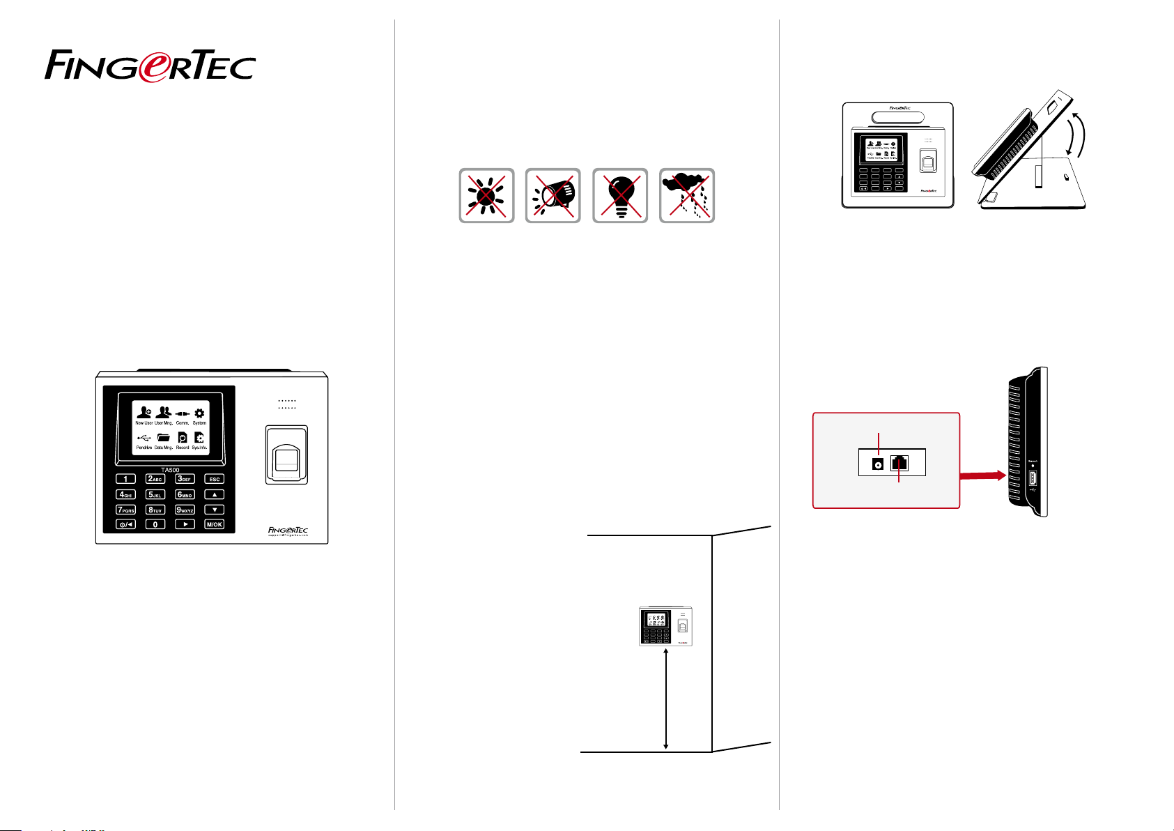
• Avoid installing the terminals in locations that have contact with
a strong light source (e.g direct sunlight, spotlight, fluorescent
light, etc)
B. FLEXI-KIT
1
7PQRS
/
TA500
2ABC 3DEF
5JKL4GHI
8TUV 9WXYZ
0
ESC
6MNO
M/OK
suppo r t @ fi n g e r te c . c o m
Installation Guide
TA500
Biometrics Time Attendance System
• Avoid installing the terminals in locations prone to high moisture
or condensation levels in the air
• The recommended installation height of the terminals from the
ground is 1.2 meter.
Step 2
Mounting Terminals
It is recommended that the terminals be mounted to a wall in
to ease the process of enrolment and verification. In a situation
whereby mounting the terminals on a wall is not an option, you
can choose to use flexi kit to convert the terminals to desktop units.
However, there are limited options for the flexi kit and some terminals might not be suitable to be placed on flexi kits.
A. MOUNT ON WALL
• After measuring the height
accordingly and make relevant marking on the wall,
drill the screws into the wall
to secure the back plate.
TA500
2ABC 3DEF ESC
1
5JKL4GHI
6MNO
7PQRS
8
TUV9WXYZ
M/OK
/
0
support@ f in g e r t
ec.com
• Attach the terminal to the
back plate and tighten the
screws. Refer to Appendix I
for dimensions and measurements of installation.
4 feet / 1.2 meter
(recommended)
FingerTec offers flexi-kit for all its time attendance models. Attach
the terminal on the flexi-kit for convenience.
Step 3
Wiring for Power Supply
POWER PORT
........
TCP/IP PORT
Please use the power adaptor provided in the package or alternatively you can opt for a linear power supply with specifications of
5VDC 2A. Plug one point of the power adapter to the terminal and
the other end to the power outlet. Don’t exceed the recom-mended
voltage or current to avoid damaging the terminal.
Step 4
Setting Up Data Communication
(Skip this step if you are using USB ash disk to transfer data)
TCP/IP – LAN Connection
For TCP/IP connection, plug the special RJ45 jack into the TCP/IP
(LAN) Port of the terminal. Connect the other end (normal RJ45 jack)
to the local area network hub or a PC. Configure the device ID, IP address, subnet mask and Gateway in the terminal (refer to the hardware user manual for details).
© 2 014 Time tec Compu ting Sdn Bhd . All rig hts rese rved. • 11 2014
Step 5
Finalizing the Installation
1. Check that all cable connections are done correctly.
2. Attach the terminal to the corresponding back plates and
tighten the screws to secure the terminal on the wall.
3. Switch on the power to the terminal.
4. Start using the terminal.
Other Accessories
FingerTec offers complementing accessories which can be used with
your terminals. These optional accessories are available at
http://accessory.fingertec.com
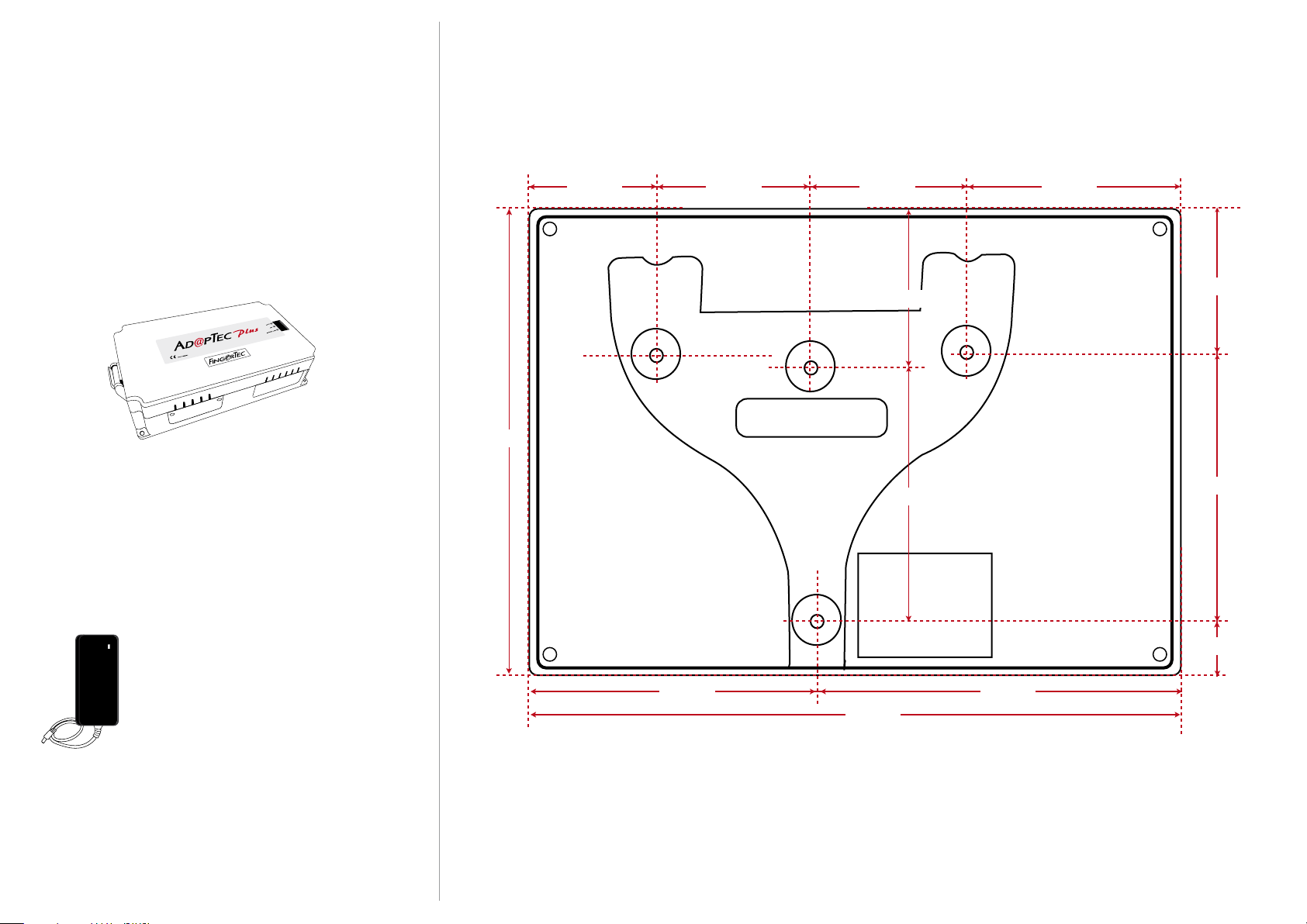
AdapTec Plus
The AdapTec Plus is a 12VDC power supply inclusive of a 110~240VAC
switching linear power. The AdapTec supplies 12VDC power to the
FingerTec terminal and door lock system as well as charges a 12VDC
7.0Ah backup battery simultaneously.
During an event of a power failure, the back up battery automatically
provides power to the terminal and maintains the door lock system.
The AdapTec Plus also prevents a secured door from being opened if
it has been tampered with.
Appendix I
Terminal Dimensions and Measurements
134 mm
40 mm40 mm44 mm 60 mm
41mm
68mm
39mm
70mm
Mini UPS
Mini UPS 12VDC is a mini portable backup power supply with 12VDC output, supplying 12VDC
power for FingerTec Time Attendance terminals.
meddled with by unauthorized persons.
Flexi Kit
A simple stand which can be used to support your terminal. You can
use Flexi-Kit and convert your terminal into a desktop unit. By installing the terminals onto a Flexi-Kit, you do not need to go through the
process of mounting your terminals on a wall. The simplicity of the
Flexi-Kit’s design ensures that it is portable and easy to set up, making it ideal as a demonstration prop too.
25mm
84 mm 100 mm
184 mm
Front View of Back Plate
 Loading...