


www.fingertec.comwww.fingertec.com
Installer Guide
UNDERSTANDING ADAPTEC TA FUNCTIONS
1
• To support FingerTec terminals that are dedicated to Time Attendance
• To support rechargeable backup battery (compatible with any DC12V Rechargeable Backup
battery) and to act as a backup power supply during power failure
• To support DC12V Siren, maximum 1A. (For TA100 series only)
UNDERSTANDING THE TECHNICAL SPECIFICATIONS
2
Dimension (mm) 198 (L) x 131 (W ) x 43 (H)
Weight 900g
Input Voltage AC 110 / 240 V (universal input)
Output Voltage DC 5V 1A and 12V 1A
Siren Output DC12V, max 1A
UNDERSTANDING THE DESIGN
3
The AdapTec TA is a power supply specially designed for FingerTec terminals for time and attendance
systems, including TA100 black and white series, TA100C series, AC100 series, and TimeLine 100 series
(which require DC 5V 1A). The AdapTec TA is intended to ease installation, to provide power supply and
to provide longer standby time during a power failure, supported by a DC12V rechargable battery.
AdapTec TA is compatible with all DC12V rechargable batteries in the market. The AdapTec TA consists
of a power supply or a power input module as well as a power output module. The AdapTec TA also
connects to other devices, which require similar power requirement of DC 5V 1A.
Note: Kindly seek FingerTec’s confirmation on device specifications via email to info@fingertec.com
2013 FingerTec Worldwide Sdn. Bhd. All rights reserved • 022013
©
3 4
1
The AdapTec TA consists of 2 main modules:
1
Power supply/power input module.
2
Power output module.
POWER SUPPLY/POWER INPUT MODULE
3
This portion is to be connected to a power source with AC110~240V. An AC current will be
supplied into this side and a DC12V 3A current will be generated as output.
4
These two cables, -V and +V are defaults and connected to the inner part of AdapTec. Please
do not remove or replace these cables.
POWER OUTPUT MODULE
5
This LED is an indicator to indicate the output is available. Please return the unit if the LED
does not light up after it is powered on.
6
These are the power outputs from the AdapTec TA. FingerTec terminals and sirens will use
these outputs. Please refer to the wiring diagram for more details.
5
6
2
WIRING DIAGRAMS (TA100 & 100C Series / AC100 / TimeLine 100)
4
STEP 1 • Connection Points
6
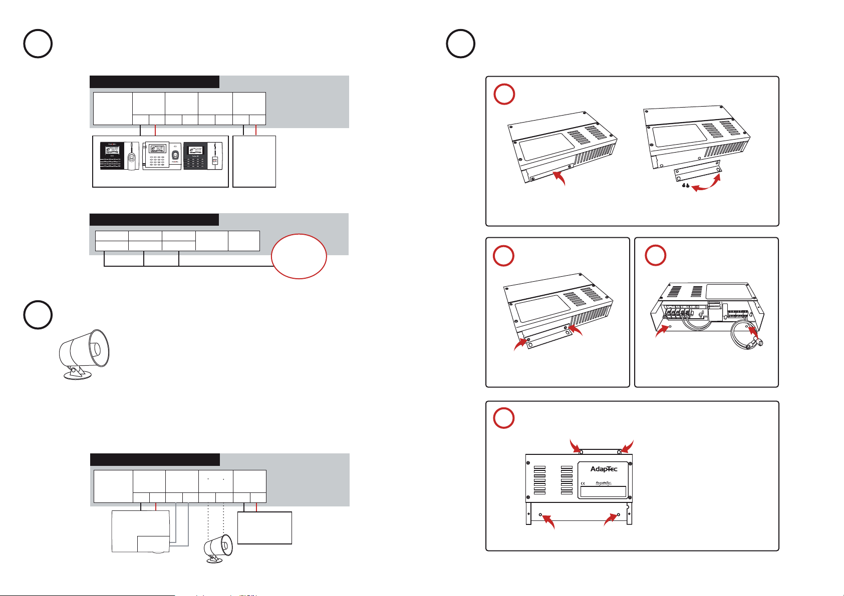
INSTALLATION
How to mount an AdapTec TA onto a wall
Power Output Module
5V Output Input Siren To Battery
OK Max 1A
5V 0 C NO 12V 0
1
2
3
ESC
MENU
4
5
6
8
9
7
0
ok
Connection points in
TA100 Series / AC100 / TimeLine 100
STEP 2 • Connect AdapTec TA to a Power Source
--- +
DC 12V
Rechargeable
Backup
Battery
Power Supply/Power Input Module
LN E -V+V
AC110~240V
L - Live
Red Blue Green
N - Neutral
E - Earth
Now you can turn on the power source and start to use the terminal for time attendance.
SIREN TO ALERT TIME ATTENDANCE REPORTING
5
Benets of using AdapTec TA with Siren
We recommend you to install the terminal using AdapTec TA, as an additional
port is readily built to receive the signal from FingerTec terminals. AdapTec TA is
outputs DC12V to connect to a siren. You do not need to source for an additional
DC12V power supply for this purpose.
AdapTec TA
Remove the L-shape piece from the AdapTec TA
1
Find an L-shape piece at the top right of an
AdapTec TA . This piece is attached to the
AdapTec TA by 2 screws.
Install the piece to the AdapTec TA
2
Attach the L-shape to the AdapTec TA as
shown and tighten the screws.
After removing the piece, you will have
one L-shape piece and 2 screws.
The other 2 holes at the bottom
3
Open the cap, look for the part shown in
the diagram and you will see 2 holes.
FUNCTION • TA100 Series
The AdapTec TA is integrated to support the scheduled siren function. You can connect a bell with
the DC12V max 1A to an AdapTec TA. TA100 series is equipped with 10 scheduled bell function.
You can preset the scheduled bell inside the TA100 series by connecting the TA100 series siren
relay to the AdapTe TA.
Power Output Module
5V Output Input Siren To Battery
OK Max 1A
5V 0 C NO 12V 0
TA100 Series
Siren relay
*Siren relay integrated on mcu
Siren
--- +
DC 12V
Rechargeable
Backup Battery
AdapTec TA
Mount the AdapTec TA on a wall
4
INPUT :AC 110 ~ 240V
OUTPUT : DC 12V 3A
Identify a location to mount the
AdapTec TA on a wall.
Fix the AdapTec TA onto the wall
by tightening the screws into the 4
holes.
 Loading...