


ENGLISH - PAGES 4-9
READ ALL INSTRUCTIONS
BEFORE OPERATING UNIT!
ESPAÑOL - PÁGINAS 10-15
¡LÉANSE ANTES DE UTILIZAR EL APARATO Y GUARDENSE PARA SU USO POSTERIOR!
FRANçAIS - PAGES 16-21
16-21
PRIERE DE LIRE AVANT L’EMPLOI ET A CONSERVER POUR UTILISATION ULTERIEURE!

 ITALIANO - PAGINE
 22-27
22-27
LEGGERE ATTENTAMENTE PRIMA DELL’USO E CONSERVARE PER UN UTILIZZO SUCCESSIV0!
DEUTSCH - SEITEN 28-33
BITTE VOR GEBRAUCH LESEN UND FÜR SPÄTEREN GEBRAUCH AUFBEWAHREN!
 - 34-39
• TO PREVENT DAMAGE, FIRE OR SHOCK HAZARD, |
• THIS UNIT MUST BE EARTH GROUNDED. |
|
|
DO NOT EXPOSE THIS UNIT TO RAIN OR MOIS- |
• UNPLUG THE AC POWER LINE CORD BEFORE |
|
TURE. |
CLEANING THE UNIT’S COVERING WITH ONLY A |
• |
NO USER SERVICEABLE PARTS INSIDE, REFER |
DAMP CLOTH; WAIT UNTIL THE UNIT IS COM- |
|
SERVICING TO QUALIFIED PERSONNEL ONLY. |
PLETELY DRY BEFORE RECONNECTING IT TO |
• DO NOT ALTER THE AC PLUG. |
POWER. |
|
• PARA EVITAR DAÑOS, INCENDIOS Y DESCARGAS |
• ESTA UNIDAD DEBE CONECTARSE CON TOMA DE |
|
|
ELÉCTRICAS, NO EXPONGA ESTA UNIDAD A LA |
TIERRA. |
|
LLUVIA NI A LA HUMEDAD. |
• DESCONECTE EL CABLE DE ALIMENTACIÓN DE |
• CONTIENE PIEZAS CUYO MANTENIMIENTO NO LO |
CA ANTES DE LIMPIAR LA CUBIERTA DE LA |
|
|
PUEDE REALIZAR EL USUARIO, SINO SÓLO PER- |
UNIDAD; ESPERE A QUE LA UNIDAD ESTÉ COM- |
|
SONAL CUALIFICADO. |
PLETAMENTE SECA ANTES DE VOLVER A CONEC- |
• NO MODIFIQUE EL ENCHUFE DE CA. |
TARLA A LA CORRIENTE. |
|
• |
POUR EVITER L'ENDOMMAGEMENT DE L'AP- |
• NE MODIFIEZ PAS LA PRISE DE CA. |
|
PAREIL, UN DEPART D'INCENDIE, OU UN CHOC |
• CET APPAREIL DOIT ETRE MIS A LA TERRE. |
|
ELECTRIQUE, NE L'EXPOSEZ JAMAIS A L'HU- |
• DEBRANCHEZ LE CABLE D'ALIMENTATION AVANT |
|
MIDITE OU A LA PLUIE. |
DE NETTOYER LE BOITIER DE L'APPAREIL ET |
•AUCUNE MAINTENANCE NE DOIT ETRE  ATTENDEZ QUE L'APPAREIL SOIT COMPLETE-
EFFECTUEE POUR LES PIECES SITUEES DANS L'APPAREIL. LES REPARATIONS ET LA MAINTENANCE DOIVENT ETRE EXECUTEES UNIQUEMENT PAR UN PERSONNEL QUALIFIE.
MENT SEC AVANT DE LE REBRANCHER SUR LE SECTEUR.
•PER EVITARE DANNI, RISCHI DI INCENDI O • QUESTA UNITÀ DEVE ESSERE COLLEGATA A
SCOSSE ELETTRICHE, NON ESPORRE QUESTA UNITÀ ALLA PIOGGIA O ALL'UMIDITÀ.
•NON CONTIENE PARTI RIPARABILI DALL'UTENTE: FARE ESEGUIRE LA MANUTENZIONE SOLTANTO DA PERSONALE QUALIFICATO.
•NON ALTERARE LA PRESA C.A.
TERRA.
•DISCONNETTERE IL CAVO DI ALIMENTAZIONE C.A. PRIMA DI PULIRE LA COPERTURA DELL'UNITÀ; ATTENDERE CHE L'UNITÀ SIA COMPLETAMENTE ASCIUTTA PRIMA DI RICOLLEGARLA ALL'ALIMENTAZIONE.
•SETZEN SIE DIESES GERÄT NIEMALS REGEN • MANIPULIEREN SIE AUF KEINEN FALL DIE NET-
ODER FEUCHTIGKEIT AUS, UM BESCHÄDIGUNG, |
|
ZANSCHLUSSBUCHSE. |
BRANDENTWICKLUNG UND ELEKTRISCHE |
• |
DAS GERÄT MUSS GEERDET SEIN. |
SCHLÄGEN ZU VERMEIDEN. |
• |
STECKEN SIE DAS NETZKABEL AUS, BEVOR SIE |
•IM GERÄT SIND KEINE ZU WARTENDEN TEILE. DAS GEHÄUSE DES GERÄTS REINIGEN.
WARTUNG UND REPERATUREN DÜRFEN NUR |
SCHLIESSEN SIE DAS GERÄT ERST WIEDER ANS |
||
VON |
QUALIFIZIERTEN |
TECHNIKERN |
STROMNETZ AN, WENN ES VOLLSTÄNDIG |
DURCHGEFÜHRT WERDEN. |
|
GETROCKNET IST. |
|
3
ULTIMATE CHORUS DSP - FEATURES
Based on the classic design of the original Fender® Ultimate Chorus™ stereo amplifier , the Ultimate Chorus DSP™ takes an evolutionary step with Digital Signal Processing. Developed in Fender’s own digital laboratory, the Ultimate Chorus DSP features 32 studio-quality stereo effects that utilize twin power-amplifiers to maintain total stereo-separation. NORMAL and DRIVE channels feature individual EQUALIZATION and REVERB/DELAY controls for added flexibility!
The DRIVE channel with exclusive Fender preand de-emphasis distortion circuitry produces the searing smooth highs and deep punch like that of an overdriven stack tube-amplifier. In addition, the MID BOOST switch and PRESENCE control provide modification of the middle and ultra-high frequencies of your sound.
The included 3-button FOOTSWITCH allows remote ON/OFF switching of the DSP stereo effects and switching between NORMAL and DRIVE channels. “Multiplexing” allows you to connect the FOOTSWITCH to remote pedal-boards with any standard 1/4-inch patch cord.
The versatility of the Ultimate Chorus DSP is greatly expanded with true-stereo and balanced-mono EFFECTS LOOP jacks which enable connection to a wide variety of equipment such as recording/sound reinforcement consoles and “add-on” Ultimate Chorus DSP amplifiers.
FCC COMPLIANCE NOTICE
This equipment has been tested and found to comply with the limits for a Class B digital device, pursuant to Part 15 of the FCC rules. These limits are designed to provide a reasonable protection against harmful interference in a residential installation. This equipment generates, uses and can radiate radio frequency energy and if not installed and used in accordance with the instructions, may cause harmful interference to radio communications. However, there is no guarantee that interference will not occur in a particular installation.
If this equipment does cause harmful interference to radio or television reception, which can be determined by turning the equipment off and on, the user is encouraged to try to correct the interference by one or more of the following measures: •Reorient or relocate the receiving antenna •Increase the separation between the equipment and receiver •Connect the equipment into an outlet on a circuit different from that of the receiver •Consult the dealer or an experienced radio/TV technician for help
4
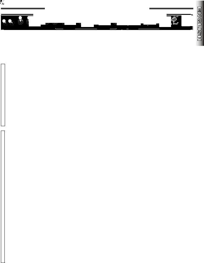
ULTIMATE CHORUS DSP - FRONT PANEL
A.INPUT 1 - A high-impedance plug-in connection for guitars or other instruments.
B.INPUT 2 - A lower-impedance plug-in connection for guitars or other instruments with active pre-amps. NOTE: Both inputs have identical impedance when used simultaneously.
•Normal Channel must be active for controls {C.-H.} to function, see DRIVE SELECT {P}.
N C. NORMAL VOLUME |
- Adjusts the overall |
loudness of the amplifier. |
|
O |
|
D. TREBLE - Adjusts the high-frequency range. |
|
R E. NORMAL CHANNEL LED - Illuminates when |
|
the Normal Channel is active. |
|
M |
|
F. MID - Adjusts the mid-frequency range. |
|
A G. BASS - Adjusts the low-frequency range. |
|
H. RVB/DLY LEVEL - |
Adjusts the amount of |
L |
|
REVERB/DELAY type DSP Effects to be mixed- |
|
in with the original dry signal. |
|
•Drive Channel must be active for controls {I.–O. and Q.–R.} to function, see DRIVE
•SELECT {P}.
I.GAIN - Adjusts the amount of pre-amp gain (distortion). Use with DRIVE VOLUME {L} to control the overall amplifier loudness.
J.MID BOOST - Activates a special preemphasis filter which accentuates mid-range
D
frequencies with this switch IN.
|
K. PRESENCE - Adjusts the the post-distortion |
|
R |
ultra-high frequency range. |
|
L. DRIVE VOLUME - Adjusts the post-distortion |
||
|
||
|
volume. Use with GAIN {I} to control overall |
|
I |
amplifier loudness. |
M.DRIVE CHANNEL LED - Illuminates when the
Drive Channel is active.
VN. TREBLE - Adjusts the high-frequency range.
O. MID - Adjusts the mid-frequency range.
E P. DRIVE SELECT -
Normal Channel is active with switch OUT,
Drive Channel is active with switch IN.
•NOTE: The Channel-Select FOOTSWITCH is disabled with this switch IN.
Q. BASS - Adjusts the low-frequency range.
•
R.RVB/DLY LEVEL - Adjusts the amount of REVERB/DELAY type DSP Effects to be mixedin with the original dry signal.
S.DEFEAT - Mutes the REVERB/DELAY type DSP Effects with this switch IN. Switch must be OUT to enable remote switching from the FOOTSWITCH.
T.TYPE - Selects one of sixteen various
REVERB/DELAY DSP Effects. The DEFEAT switch {S} must be OUT, the LEVEL controls {H & R} must be above “1,” and REVERB/DELAY on the remote FOOTSWITCH (if used) must be active for this DSP effect to be heard. (See “DSP STEREO EFFECTS - CONTROLS,” page 6.)
U.DEFEA T - Mutes the CHORUS/MODULATION type DSP Effects with this switch IN. This switch must be OUT to enable remote switching from the FOOTSWITCH.
V.LEVEL - Adjusts the amount of
CHORUS/MODULATION type DSP Effects to be mixed in with the original dry signal.
W.TYPE - This control selects one of sixteen various CHORUS/MODULATION DSP Effects. The
DEFEAT switch {U} must be OUT, the |
LEVEL |
control {V} must be above |
“1,” and |
CHORUS/MODULATION on the |
remote |
FOOTSWITCH (if used) must be active for this DSP Effect to be heard. (See “DSP STEREO EFFECTS - CONTROLS,” page 6.)
X.RATE - Adjusts the sweep RATE of the
CHORUS/MODULATION type DSP Effects. Lower numbers correspond to slower sweep
RATES.
Y.DSP PEAK LED - Flashing of this LED indicates possible clipping (distortion) in either of the DSP effects circuits. Periodic flashing is normal. If the LED stays on and undesirable
distortion is heard, try reducing LEVELS {H, R, V} or the VOLUME controls {C & L}.
Z. POWER SWITCH - Press IN the:
•Lower-half to switch ON the amplifier.
•Upper-half to switch OFF the amplifier.
5

DSP STEREO EFFECTS - CONTROLS
|
• Select from 5 TYPES of REVERB/DELA Y effects (FIG. A): |
|
DELAY/REVERB - A blend of delay and reverb |
|
DELAY - A multi-tap digital delay |
|
ROOM - A simulation of medium-size room acoustics |
|
HALL - A simulation of large-size hall acoustics |
|
PLATE - A simulation of studio plate reverb |
|
A range of preset REVERB/DELAY RATES can be selected |
|
within each TYPE (numbered in sets, FIG. A). The preset |
|
RATES get longer going clockwise within that TYPE (direction |
|
of arrows, FIG. A). For instance, presets numbered “1” in |
FIG. A |
FIG. A, will have the fastest REVERB/DELAY RATES. |
• Select from 3 TYPES of CHORUS/MODULA TION effects (FIG. B):
CHORUS 1 - A modern, lush chorus
CHORUS 2 - A reproduction of the chorus effect in the original Ultimate Chorus amp FLANGE - An enhanced short-delay effect
A range of preset CHORUS/MODULATION sweep DEPTHS can be selected within each TYPE (numbered in sets, FIG. B). The preset sweep DEPTHS get deeper going clockwise within that TYPE (direction of arrows, FIG. B). For instance, presets numbered “1” in FIG. B, will have the shallowest CHORUS/MODULATION sweep DEPTHS .
• Adjust the CHORUS/MODULATION sweep
RATE with the RATE knob (FIG. C). The sweep RATE gets faster going clockwise (direction of arrow in FIG. C). For instance, the RATE numbered “1” in FIG. C is the slowest sweep RATE.
FIG. B |
FIG. C |
6
ULTIMATE CHORUS DSP - REAR PANEL
A.IEC LINE CORD CONNECTOR - The line cord must be connected to a grounded AC receptacle in accordance with the voltage and frequency ratings as listed on the rear panel under INPUT POWER.
B.FOOTSWITCH JACK - Plug-in connection for the FOOTSWITCH (P/N 0055592000) for remote switching between channels, and ON/OFF switching of both DSP effects circuits. NOTE: For proper operation of the
FOOTSWITCH, the DRIVE SELECT* switch and both DSP effects DEFEAT* switches must all be OUT. (A speaker-grade cord is preferable to a coax guitar cord for connecting the FOOTSWITCH.)
C.STEREO SEND - This jack provides a linelevel stereo output from the pre-amp and both DSP effects circuits of the Ultimate Chorus DSP. This output can be used in conjunction with the STEREO RETURN {D} as a patch point for external stereo effects devices. (See “EFFECTS LOOPS - CONNECTION DIAGRAMS,” page 8). This send can also be used to feed a stereo signal to two channels of a recording/sound-rein- forcement mixer. To drive another Ultimate Chorus DSP as an “add-on” amplifier, connect a shielded stereo cord from the STEREO SEND jack of the “master” amplifier to the STEREO RETURN jack {D} of the “add-on” amplifier.
D.STEREO RETURN - This stereo jack inputs signal directly to the left and right poweramps. It automatically disconnects the preamp and DSP Effects circuits when used. This is useful when using the stereo effects loop option detailed above, or when using a second Ultimate Chorus DSP as an “add-on” amplifier preserving the stereo signal of the “master” Ultimate Chorus DSP amplifier.
•NOTE: The STEREO jacks {C & D} are standard 1/4-inch Tip-Ring-Sleeve types, with:
•Left channel signal on the Tip •Right channel signal on the Ring
E.MONO SEND - This jack provides an imped- ance-balanced mono output signal from the pre-amp at a point before the DSP Effects circuits. This output can be used in conjunction with the MONO RETURN jack {F} as a patch point for external mono effects devices. (See “EFFECTS LOOPS - CONNECTION DIAGRAMS,” page 8) The MONO SEND jack can also be used to send recording/sound-rein- forcement consoles a dry signal. Additionally this output can be used to drive a second Ultimate Chorus DSP as an “add-on” amplifier. This is done by connecting a standard guitar cord from the MONO SEND jack of the “master” amplifier to the MONO RETURN jack {F} of the “add-on” amplifier.
F.MONO RETURN - This balanced jack inputs signal to the stereo DSP Effects circuitry which drives the stereo power-amp section. It automatically disconnects the pre-amp signal when used. This is useful when using the mono effects loop option detailed above or when using the Ultimate Chorus DSP as an “add-on” amplifier for a mono signal source. The DSP Effects are active in the “add-on” amplifier so that a true stereo image will be generated if the DSP Effects are used. NOTE: In order to function properly, a dummy plug or an extra guitar cord must be inserted into INPUT 2* on the “addon” amplifier with its VOLUME* controls turned down.
*These controls are located on the Front Panels.
7
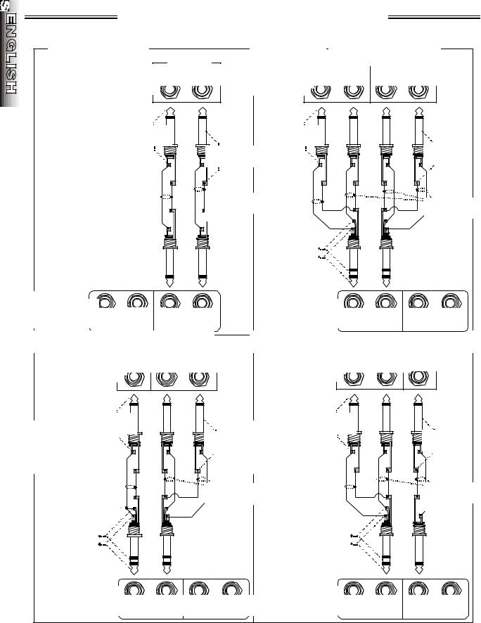
EFFECTS LOOPS - CONNECTION DIAGRAMS
8

ULTIMATE CHORUS DSP - SPECIFICATIONS
|
TYPE: |
PR 436 |
|
|
|
PART NUMBER: |
022-6701-020 (120V, 60Hz) |
||
|
|
022-6731-020 (240V, 50Hz) Aust |
||
|
|
022-6741-020 (230V, 50Hz) UK |
||
|
|
022-6761-020 (230V, 50Hz) Eur |
||
|
|
022-6771-020 (100V, 50/60Hz) |
||
|
POWER REQUIREMENT: |
360W |
|
|
POWER AMP |
POWER OUTPUT: |
65W per channel, (130W Total) @ 5% THD |
||
RATED LOAD IMPEDANCE: |
8Ω per channel |
|
||
|
SENSITIVITY: |
1.4V RMS |
|
|
PREAMP |
INPUT IMPEDANCE: |
INPUT 1: >1MΩ, INPUT 2: >130kΩ |
||
|
NOMINAL LEVEL: |
INPUT 1: 100mV, |
INPUT 2: 200mV |
|
|
MONO EFFECTS LOOP: |
NOMINAL LEVEL: -10dBv |
||
|
|
SEND OUTPUT IMPEDANCE: 1kΩ (Balanced) |
||
|
|
RETURN INPUT IMPEDANCE: 18kΩ (Balanced) |
||
STEREO EFFECTS LOOP: |
NOMINAL LEVEL: -10dBv |
|||
|
|
SEND OUTPUT IMPEDANCE: 1kΩ |
||
|
|
RETURN INPUT IMPEDANCE: 100kΩ |
||
|
|
(Specifications for each channel: |
||
|
|
Left on Tip, Right on Ring) |
||
_____________________________________________________________________________ |
||||
SPEAKER COMPLEMENT: |
TWO FENDER SPECIAL DESIGN |
|||
|
|
12”, 8Ω SPEAKERS (P/N 0025923000) |
||
|
DIMENSIONS: |
HEIGHT: |
18 1/2 in. |
(47 cm) |
|
|
WIDTH: |
26 1/8 in. |
(66 cm) |
|
|
DEPTH: |
10 1/4 in. |
(26 cm) |
|
WEIGHT: |
|
47 lb. |
(21.3 kg) |
Product specifications are subject to change without notice
9
ULTIMATE CHORUS DSP - FUNCIONES
Basado en el diseño clásico del amplificador estéreo original Ultimate Chorus™ de Fender® , Ultimate Chorus® DSP supone todo un avance al utilizar el procesamiento de señal digital (Digital Signal Processing). Desarrollado en el laboratorio digital de Fender, Ultimate Chorus DSP dispone de 32 efectos estéreo con calidad de estudio que utilizan amplificadores dobles para el mantenimiento de una separación estéreo total. ¡Los canales de FUNCIONAMIENTO y NORMAL unidos a los controles de ECUALIZACIÓN y REVERB/DELAY individuales lo convierten en un verdadero amplificador de dos canales!
El canal de FUNCIONAMIENTO dispone de un sistema de circuitos de distorsión de preacentuación y desacentuación exclusivo de Fender que genera altos suaves y de gran fuerza como si se tratase de un amplificador distorsionado de tubo apilado. Además, el conmutador AUMENTAR
MEDIOS y el control de PRESENCIA permiten modificar las frecuencias ultra altas y medias del sonido.
El CONMUTADOR DE PEDAL de 3 botones que se incluye permite activar o desactivar de forma remota los efectos estéreo DSP y alternar entre los canales de FUNCIONAMIENTO y NORMAL. La “multiplexión” permite conectar el CONMUTADOR DE PEDAL a los paneles de pedal remoto mediante cualquier cable de conexión de 1/4 pulgadas.
La versatilidad de Ultimate Chorus DSP ha aumentado considerablemente gracias a los BUCLES DE EFECTOS mono con balance y estéreo real que permiten la conexión con gran variedad de equipos, entre los que se incluyen las consolas de grabación o de refuerzo de sonido y otros amplificadores Ultimate Chorus DSP.
AVISO DE CONFORMIDAD DE FCC
Este equipo ha sido probado y se ha determinado que cumple con los requisitos para los dispositivos digitales de Clase B, de acuerdo con el apartado 15 de la normativa FCC. Estas restricciones tienen como finalidad proporcionar una protección razonable frente a interferencias en instalaciones residenciales. Este equipo genera, usa y puede emitir energía de radiofrecuencia y, si no se instala y utiliza conforme a las instrucciones que se proporcionan, puede causar interferencias que afecten a las comunicaciones por radio. Sin embargo, no se garantiza que dicha interferencia no se producirá en algún tipo de instalación particular.
Si este equipo causara interferencia en la recepción por radio o televisión, lo cual se puede determinar encendiendo y apagando el equipo, el usuario puede intentar corregirla aplicando una o varias de las siguientes medidas: •Cambiar la orientación o ubicación de la antena receptora •Aumentar la separación entre el equipo y el receptor •Conectar el equipo a una toma de corriente que se encuentre en un circuito distinto al del receptor •Si es necesario, consultar al distribuidor o a un técnico especialista en radio/televisión para obtener ayuda
10
ULTIMATE CHORUS DSP - PANEL FRONTAL
A.INPUT 1 : Conexión de entrada de alta impedancia para guitarras u otros instrumentos.
B.INPUT 2 : Conexión de entrada de baja impedancia para guitarras u otros instrumentos con preamplificadores activos. NOTA: ambas entradas tienen una impedancia idéntica cuando se utilizan simultáneamente.
• El canal normal debe estar activo para el
Nfuncionamiento de los controles {C.-H.}, (SELECCIÓN DE FUNCIONAMIENTO {P} hacia
Oafuera).
C. NORMAL VOLUME : Ajusta el volumen global del R amplificador.
D. TREBLE : Ajusta la gama de frecuencias altas.
ME. NORMAL CHANNEL LED : Se ilumina cuando el canal normal está activo.
A F. MID: Ajusta la gama de frecuencias medias.
G. BASS: Ajusta la gama de frecuencias bajas.
L
H. RVB/DLY LEVEL DE REVERB/DELAY: Ajusta la cantidad de efectos DSP del tipo REVERB/DELAY que se van a mezclar con la señal en seco original.
•El canal de funcionamiento debe estar activo para el funcionamiento de los controles {I.–O. y Q.–R.}, consulte SELECCIÓN DE FUNCIONAMIENTO {P}.
•I. GAIN : Ajusta el nivel de ganancia del preamplificador (distorsión). Utilice esta función
junto con el VOLUMEN DE FUNCIONAMIENTO {L} para controlar el volumen global del amplificador.
J. MID BOOST : Activa un filtro de preacentuación especial que enfatiza las frecuencias medias
Dcuando este conmutador está pulsado hacia dentro.
K. PRESENCIA: Ajusta la gama de frecuencias ultra
Raltas que se produce después de la distorsión.
L.DRIVE VOLUME : Ajusta el volumen después de la distorsión. Utilice esta función junto con la
GANANCIA {I} para controlar el volumen global del
I
amplificador.
M.DRIVE CHANNEL LED : Se ilumina cuando el canal de funcionamiento está activo.
VN. TREBLE : Ajusta la gama de frecuencias altas.
O. MID: Ajusta la gama de frecuencias medias.
P. DRIVE SELECT:
E
El canal normal está activo cuando el conmutador está hacia afuera, El canal de funcionamiento está activo cuando el conmutador está pulsado hacia dentro.
•NOTA: el CONMUTADOR DE PEDAL de selección de canal se desactiva cuando se pulsa hacia dentro este conmutador.
•Q. BASS: Ajusta la gama de frecuencias bajas.
R.RVB/DLY LEVEL DE REVERB/DELAY: Ajusta la cantidad de efectos DSP del tipo REVERB/DELAY que se van a mezclar con la señal en seco original.
S.DEFEA T : Silencia los efectos DSP del tipo REVERB/DELAY cuando este conmutador está pulsado hacia dentro. Para poder activar la conmutación remota desde el CONMUTADOR DE PEDAL este conmutador debe estar hacia afuera.
T.TYPE: Seleccione uno de los 16 efectos DSP del tipo REVERB/DELAY. Para que se pueda oír este efecto DSP, el conmutador ANULAR {S} debe estar hacia afuera, los controles de NIVEL {H & R} deben estar por encima de “1” y el CONMUTADOR DE PEDAL (si se utiliza) debe estar activo. Consulte “EFECTOS ESTÉREO DSP: CONTROLES” en la página 12.
U.DEFEA T : Silencia los efectos DSP del tipo CHORUS/MODULACIÓN cuando este conmutador está pulsado hacia dentro. Para poder activar la conmutación remota desde el CONMUTADOR DE PEDAL este conmutador debe estar hacia afuera.
V.LEVEL : Ajusta la cantidad de efectos DSP del tipo CHORUS/MODULACIÓN que se van a mezclar con la señal en seco original.
W.TYPE : Este control selecciona uno de los dieciséis efectos DSP del tipo CHORUS/MODULACIÓN. Para que se pueda oír este efecto DSP, el conmutador ANULAR {U} debe estar hacia afuera, el control de NIVEL {V} debe estar por encima de “1” y la función
CHORUS/MODULACIÓN del CONMUTADOR DE PEDAL(si se utiliza) debe estar activada. Consulte “EFECTOS ESTÉREO DSP: CONTROLES” en la página 12.
X.RATE : Ajusta la VELOCIDAD de barrido de los efectos DSP del tipo CHORUS/ MODULACIÓN. Los números más bajos indican una
VELOCIDAD. de barrido menor.
Y.DSP PEAK LED : Si este LED parpadea indica la posibilidad de que se produzcan cortes (distorsión) en alguno de los circuitos de efectos DSP. Es normal que parpadee periódicamente. Si el LED permanece encendido y se escucha una distorsión no deseada, intente reducir los controles de
VOLUMEN {C & L} o los NIVELES {H, R, V} .
Z.POWER SWITCH : Pulse hacia dentro:
•La mitad inferior para encender el amplificador.
•La mitad superior para apagar el amplificador.
11

EFECTOS ESTÉREO DIGITALES - CONTROLES
•[REVERB/DELA Y] (FIGURA A): Seleccione entre 5 [TYPES] TIPOS de efectos con la rueda [TYPE] TIPO:
[DELAY/REVERB]: mezcla de delay y reverb
[DELAY]: efecto delay digital de varias repeticiones
[ROOM]: simulación de la acústica de una habitación de
dimensiones medias
[HALL]: simulación de la acústica de una sala de gran tamaño
[PLATE]: simulación del efecto reverb que se utiliza en los estudio
de grabación
Dentro de cada [TYPE] TIPO es posible seleccionar entre un rango de
PORCENTAJES DE [REVERB/DELA Y] predefinidos (numerados en
conjuntos, FIGURA A. Estos PORCENTAJES predefinidos serán mayores si se avanza en el sentido de las agujas del reloj dentro de dicho [TYPE] TIPO (dirección de las flechas, FIGURA A). Por ejemplo, los valores predefinidos con el número “1” en la FIGURA A, tendrán los POR-
CENTAJES DE [REVERB/DELA Y] más pequeños.
FIGURA A
•[CHORUS/MODULATION] CHORUS/MODULACIÓN(FIGURA B): Seleccione entre 3 [TYPES] TIPOS de efectos con la rueda [TYPE] TIPO:
[CHORUS] 1: coro moderno y suntuoso
[CHORUS 2]: reproducción del efecto en el amplificador original [Ultimate Chorus] [FLANGE]: efecto de delay corto mejorado
Dentro de cada [TYPE] TIPO es posible seleccionar entre un rango de PROFUNDIDADES de barrido [CHORUS/MODULATION] CHORUS/ MODULACIÓN predefinidas (numeradas en conjuntos, FIGURA B). Estas PROFUNDIDADES de barrido predefinidas aumentan si se avanza en el sentido de las agujas del reloj dentro de dicho [TYPE] TIPO (dirección de las flechas, FIGURA B). Por ejemplo, los valores predefinidos con el número “1” en la FIGURA B, tendrán las PROFUNDIDADES de barrido [CHORUS/MODULATION] CHORUS/MODULACIÓN más superficiales.
• [CHORUS/MODULATION] CHORUS/MODULATION (FIGURA C): Ajuste la [RATE] VELOCIDAD de barrido con la rueda [RATE] VELOCIDAD. Las [RATES] VELOCIDADES de barrido aumentan en el sentido de las agujas de reloj (dirección de la flecha en la FIGURA C). Por ejemplo, la [RATE] VELOCIDAD con el número “1” en la FIGURA C es la [RATE] VELOCIDAD de barrido más lenta.
FIGURA B |
FIGURA C |
12
 Loading...