

Page 1

#
FANUC AC SPINDLE MOTOR @* series
FANUC AC SPINDLE MOTOR
PARAMETER MANUAL
* series
B-65280EN/05
Page 2

• No part of this manual may be reproduced in any form.
• All specifications and designs are subject to change without notice.
In this manual we have tried as much as possible to describe all the various matters.
However, we cannot describe all the matters which must not be done, or which cannot be
done, because there are so many possibilities.
Therefore, matters which are not especially described as possible in this manual should be
regarded as ”impossible”.
This manual contains the program names or device names of other companies, some of
which are registered trademarks of respective owners. However, these names are not
followed by or in the main body.
Page 3

B-65280EN/05 DEFINITION OF WARNING, CAUTION, AND NOTE
DEFINITION OF WARNING, CAUTION, AND NOTE
This manual includes safety precautions for protecting the user and
preventing damage to the machine. Precautions are classified into
Warning and Caution according to their bearing on safety. Also,
supplementary information is described as a Note. Read the Warning,
Caution, and Note thoroughly before attempting to use the machine.
WARNING
Applied when there is a danger of the user being
injured or when there is a damage of both the user
being injured and the equipment being damaged if
the approved procedure is not observed.
CAUTION
Applied when there is a danger of the equipment
being damaged, if the approved procedure is not
observed.
NOTE
The Note is used to indicate supplementary
information other than Warning and Caution.
- Read this manual carefully, and store it in a safe place.
s-1
Page 4

Page 5

B-65280EN/05 PREFACE
PREFACE
This manual describes the parameters and functions of the FANUC
servo amplifier αi/βi series spindle. This manual is divided into four
parts and appendix. Part I describes the αi series spindle, Part II
describes the βi series spindle, Part III describes the αCi series spindle,
and Part IV describes the Bis series spindle.
Unless otherwise noted, the parameter numbers for FANUC Series 16i
are used in the text. When using any other model, reference the
corresponding parameter numbers.
The table below indicates the abbreviated model names used with the
parameter numbers.
Product name
FANUC Series 30i Series 30i
FANUC Series 31i Series 31i
FANUC Series 32i Series 32i
FANUC Series 16i Series 16i
FANUC Series 18i Series 18i
FANUC Series 21i Series 21i
FANUC Series 0i Series 0i
FANUC Series 15i Series 15i 15i
Abbreviated model
name in text
For detailed information indicating which model each function
described in this manual can be used with, refer to the manual of each
CNC. For the package specifications, in particular, refer to the CNC
manual.
The manuals related to the αi/βi series spindle are listed below.
(1) FANUC AC SPINDLE MOTOR αi series DESCRIPTIONS
(B-65272EN)
(2) FANUC AC SPINDLE MOTOR αCi series DESCRIPTIONS
(B-65372EN)
(3) FANUC AC SPINDLE MOTOR βi series DESCRIPTIONS
(B-65312EN)
(4) FANUC SERVO AMPLIFIER αi series DESCRIPTIONS
(B-65282EN)
(5) FANUC SERVO AMPLIFIER βi series DESCRIPTIONS
(B-65322EN)
(6) FANUC SERVO MOTOR αis/αi series,
FANUC SPINDLE MOTOR αi series,
FANUC SERVO AMPLIFIER αi series
MAINTENANCE MANUAL (B-65285EN)
(7) FANUC SERVO MOTOR βis series,
FANUC SPINDLE MOTOR βi series,
FANUC SERVO AMPLIFIER βi series
MAINTENANCE MANUAL (B-65325EN)
Abbreviated model
name in table
30i
16i
p-1
Page 6

PREFACE B-65280EN/05
(8) FANUC AC SPINDLE MOTOR αi/βi series
PARAMETER MANUAL (B-65280EN)
(9) FANUC AC SPINDLE MOTOR αi
(B-65292EN)
B series DESCRIPTIONS
p-2
Page 7

B-65280EN/05 TABLE OF CONTENTS
TABLE OF CONTENTS
DEFINITION OF WARNING, CAUTION, AND NOTE .................................s-1
PREFACE....................................................................................................p-1
I. FANUC AC SPINDLE MOTOR αi series
1 START-UP............................................................................................... 3
1.1 START-UP PROCEDURE............................................................................. 4
1.2 SPINDLE SERIAL INTERFACE (Optional function) ...................................... 5
1.2.1 Parameters Related to Spindle Serial Output ...........................................................5
1.2.2 Automatic Spindle Parameter Initialization .............................................................6
1.2.3 Diagnosis (Diagnosis Screen)...................................................................................7
1.2.4 Alarm ........................................................................................................................8
1.3 PARAMETERS RELATED TO DETECTORS.............................................. 10
1.3.1 List of Parameters for Detectors.............................................................................10
1.3.2 Details of Parameters for Detectors........................................................................12
1.3.3 Typical Detector Configurations ............................................................................21
2 EXPLANATION OF OPERATION MODES........................................... 28
2.1 VELOCITY CONTROL MODE.....................................................................29
2.1.1 Start-up Procedure..................................................................................................29
2.1.2 Overview ................................................................................................................29
2.1.3 System Configuration.............................................................................................29
2.1.4 List of I/O Signals (CNC↔PMC)..........................................................................30
2.1.5 Related Parameters .................................................................................................34
2.1.6 Details of Related Parameters ................................................................................36
2.1.7 Troubleshooting .....................................................................................................46
2.2 POSITION CODER METHOD SPINDLE ORIENTATION
(Optional function) .......................................................................................50
2.2.1 Start-up Procedure..................................................................................................50
2.2.2 Overview ................................................................................................................51
2.2.3 Feature....................................................................................................................51
2.2.4 System Configuration.............................................................................................52
2.2.5 Stop Position Specification Method .......................................................................54
2.2.6 I/O Signals (CNC ↔ PMC) ...................................................................................55
2.2.7 Examples of Sequences ..........................................................................................59
2.2.8 Related Parameters .................................................................................................62
c-1
Page 8

TABLE OF CONTENTS B-65280EN/05
2.2.9 Details of Related Parameters ................................................................................63
2.2.10 Calculating the Position Gain for Orientation ........................................................68
2.2.11 Adjusting the Orientation Stop Position Shift Parameter.......................................69
2.2.12 Calculating the Orientation Time ...........................................................................71
2.3 RIGID TAPPING (Optional function)............................................................ 73
2.3.1 Start-up Procedure..................................................................................................73
2.3.2 Overview ................................................................................................................73
2.3.3 System Configuration.............................................................................................74
2.3.4 List of I/O Signals (CNC ↔ PMC)........................................................................77
2.3.5 Sequence.................................................................................................................79
2.3.6 Related Parameters .................................................................................................80
2.3.7 Details of Related Parameters ................................................................................82
2.3.8 Parameter Setting Procedure ..................................................................................89
2.3.9 Adjustment Procedure ............................................................................................98
2.3.10 Diagnosis (Diagnosis Screen)...............................................................................104
2.3.11 Alarm ....................................................................................................................106
2.4 Cs CONTOURING CONTROL (Optional function) .................................... 109
2.4.1 Start-up Procedure................................................................................................109
2.4.2 Overview ..............................................................................................................110
2.4.3 System Configuration...........................................................................................110
2.4.4 List of I/O Signals (CNC ↔ PMC)......................................................................112
2.4.5 Examples of Sequences ........................................................................................114
2.4.6 Related Parameters ...............................................................................................115
2.4.7 Details of Related Parameters ..............................................................................117
2.4.8 Diagnosis (Diagnosis Screen)...............................................................................126
2.4.9 Alarm ....................................................................................................................126
2.5 SPINDLE SYNCHRONOUS CONTROL (Optional function)...................... 127
2.5.1 Start-up Procedure................................................................................................127
2.5.2 Overview ..............................................................................................................128
2.5.3 System Configuration...........................................................................................129
2.5.4 Explanation of Operation .....................................................................................136
2.5.5 I/O Signals (CNC ↔ PMC) .................................................................................137
2.5.6 Examples of Sequences ........................................................................................141
2.5.7 Related Parameters ...............................................................................................146
2.5.8 Details of Related Parameters ..............................................................................147
2.5.9 Number of Error Pulses in Spindle Synchronous Control....................................155
2.5.10 Specifying a Shift Amount for Spindle Phase Synchronous Control...................156
c-2
Page 9

B-65280EN/05 TABLE OF CONTENTS
2.5.11 Diagnosis (Diagnosis Screen)...............................................................................156
2.5.12 Alarm ....................................................................................................................157
2.6 SPECIFICATIONS COMMON TO ALL OPERATION MODES.................. 158
2.6.1 Overview ..............................................................................................................158
2.6.2 List of I/O Signals (CNC ↔ PMC)......................................................................158
2.6.3 Parameters ............................................................................................................163
2.6.4 Details of Parameters............................................................................................166
2.6.5 Diagnosis (Diagnosis Screen)...............................................................................176
3 I/O SIGNALS (CNC ↔ PMC) ..............................................................178
3.1 INPUT SIGNALS (PMC→CNC→SPM)...................................................... 179
3.1.1 List of Input Signals .............................................................................................179
3.1.2 Explanation of Input Signals ................................................................................180
3.1.3 Details of Input Signals ........................................................................................182
3.2 OUTPUT SIGNALS (SPM→CNC→PMC).................................................. 192
3.2.1 List of Output Signals...........................................................................................192
3.2.2 Explanation of Output Signals .............................................................................193
3.2.3 Details of Output Signals .....................................................................................195
4 ADJUSTMENT .................................................................................... 202
4.1 VELOCITY LOOP GAIN ADJUSTMENT ................................................... 203
4.1.1 Overview ..............................................................................................................203
4.1.2 Parameters ............................................................................................................203
4.1.3 Adjustment Procedure ..........................................................................................206
4.1.4 Additional Information (Position Gain Adjustment)............................................207
4.2 MACHINE RESONANCE ELIMINATION................................................... 208
4.2.1 TCMD Filter.........................................................................................................208
4.2.2 HRV Filter............................................................................................................209
4.2.3 Disturbance Input Function ..................................................................................212
4.3 AMPLITUDE RATIO/PHASE DIFFERENCE COMPENSATION
FUNCTION ................................................................................................ 217
5 FUNCTION DESCRIPTIONS .............................................................. 222
5.1 SPEED RANGE SWITCHING CONTROL (Optional function)................... 223
5.1.1 Overview ..............................................................................................................223
5.1.2 Series and Editions of Applicable Spindle Software............................................223
5.1.3 Configuration .......................................................................................................223
5.1.4 I/O Signals (CNC ↔ PMC) .................................................................................224
5.1.5 Sequence...............................................................................................................228
c-3
Page 10

TABLE OF CONTENTS B-65280EN/05
5.1.6 List of Related Parameters....................................................................................230
5.1.7 Details of Related Parameters ..............................................................................231
5.1.8 Parameter-specified Switching between High- and Low-speed Characteristics ..233
5.2 SPINDLE SWITCHING CONTROL ........................................................... 235
5.2.1 Overview ..............................................................................................................235
5.2.2 Series and Editions of Applicable Spindle Software............................................235
5.2.3 Configuration .......................................................................................................235
5.2.4 Details of Specifications.......................................................................................236
5.2.5 Restrictions...........................................................................................................236
5.2.6 I/O Signals (CNC↔PMC) ...................................................................................237
5.2.7 Sequence...............................................................................................................240
5.2.8 List of Related Parameters....................................................................................242
5.2.9 Details of Related Parameters ..............................................................................242
5.2.10 Parameter Setting Procedure ................................................................................245
5.2.11 Supplementary Descriptions about Parameters ....................................................246
5.3 INCRMENTAL COMMAND TYPE SPINDLE ORIENTATION
(SPINDLE ROTATION SPEED CONTROL) (Optional function)................ 247
5.3.1 Overview ..............................................................................................................247
5.3.2 Series and Editions of Applicable Spindle Software............................................247
5.3.3 System Configuration...........................................................................................248
5.3.4 I/O Signals(CNC↔PMC) ....................................................................................251
5.3.5 Examples of Sequences ........................................................................................253
5.3.6 List of Related Parameters....................................................................................256
5.3.7 Details of Related Parameters ..............................................................................256
5.4 HIGH-SPEED SPINDLE ORIENTATION (Optional function)..................... 257
5.4.1 Overview ..............................................................................................................257
5.4.2 Series and Editions of Applicable Spindle Software............................................257
5.4.3 System Configuration...........................................................................................257
5.4.4 I/O Signals (CNC↔PMC) ...................................................................................260
5.4.5 Sequence...............................................................................................................262
5.4.6 List of Related Parameters....................................................................................265
5.4.7 Details of Related Parameters ..............................................................................266
5.4.8 Spindle Data Used in Tuning ...............................................................................271
5.4.9 Tuning Procedure .................................................................................................272
5.5 SPINDLE ORIENTATION DURING SPINDLE SYNCHRONIZATION
CONTROL (Optional function)................................................................... 278
5.5.1 Overview ..............................................................................................................278
c-4
Page 11

B-65280EN/05 TABLE OF CONTENTS
5.5.2 Series and Editions of Applicable Spindle Software............................................278
5.5.3 Specification.........................................................................................................279
5.5.4 I/O Signals (CNC ↔ PMC) .................................................................................281
5.5.5 Sequence...............................................................................................................285
5.5.6 List of Related Parameters....................................................................................287
5.5.7 Details of Related Parameters ..............................................................................288
5.6 SPINDLE FINE ACC./DEC. (FAD) FUNCTION ......................................... 290
5.6.1 Overview ..............................................................................................................290
5.6.2 Series and Editions of Applicable Spindle Software............................................290
5.6.3 Block Diagram .....................................................................................................291
5.6.4 Parameters ............................................................................................................291
5.6.5 Diagnosis (Diagnosis Screen)...............................................................................293
5.6.6 Status Errors .........................................................................................................293
5.6.7 Cautions................................................................................................................294
5.7 UNEXPECTED DISTURBANCE TORQUE DETECTION FUNCTION
(Optional function) .....................................................................................296
5.7.1 Overview ..............................................................................................................296
5.7.2 Series and Editions of Applicable Spindle Software............................................296
5.7.3 I/O Signals (CNC↔PMC) ...................................................................................297
5.7.4 List of Related Parameters....................................................................................298
5.7.5 Details of Related Parameters ..............................................................................298
5.7.6 Parameter Tuning Procedure ................................................................................300
5.8 SPINDLE EGB (SPINDLE ELECTRONIC GEAR BOX)
(Optional function) .....................................................................................302
5.8.1 Overview ..............................................................................................................302
5.8.2 Series and Editions of Applicable Spindle Software............................................302
5.8.3 System Configuration...........................................................................................303
5.8.4 Block Diagram .....................................................................................................306
5.8.5 I/O Signals (CNC ↔ PMC) .................................................................................307
5.8.6 Examples of Sequences ........................................................................................307
5.8.7 List of Related Parameters....................................................................................308
5.8.8 Details of Related Parameters ..............................................................................309
5.8.9 Diagnosis Signal Related to Spindle EGB ...........................................................312
5.8.10 Status Errors Related to Spindle EGB..................................................................312
5.8.11 Alarms ..................................................................................................................313
5.9 DIFFERENTIAL SPINDLE SPEED CONTROL .........................................314
5.9.1 Overview ..............................................................................................................314
c-5
Page 12

TABLE OF CONTENTS B-65280EN/05
5.9.2 Series and Editions of Applicable Spindle Software............................................314
5.9.3 Configuration .......................................................................................................315
5.9.4 Description ...........................................................................................................316
5.9.5 I/O Signals (CNC↔PMC) ...................................................................................316
5.9.6 Examples of Sequences ........................................................................................317
5.9.7 List of Related Parameters....................................................................................318
5.9.8 Details of Related Parameters ..............................................................................318
5.9.9 Status Errors on Differential Spindle Speed Control ...........................................318
5.10 DUAL POSITION FEEDBACK FUNCTION (Optional function) ................. 319
5.10.1 Overview ..............................................................................................................319
5.10.2 Series and Editions of Applicable Spindle Software............................................319
5.10.3 Block Diagram .....................................................................................................320
5.10.4 List of Related Parameters....................................................................................321
5.10.5 Details of Related Parameters ..............................................................................321
5.10.6 SPM Alarm...........................................................................................................325
5.11 TORQUE TANDEM CONTROL FUNCTION (Optional function) ............... 326
5.11.1 Overview ..............................................................................................................326
5.11.2 Series and Editions of Applicable Spindle Software............................................326
5.11.3 System Configuration...........................................................................................327
5.11.4 I/O Signals (CNC ↔ PMC) .................................................................................329
5.11.5 Examples of Sequences ........................................................................................332
5.11.6 Parameters ............................................................................................................336
5.11.7 Alarm and Status Error.........................................................................................339
5.12 MAGNETIC SENSOR METHOD SPINDLE ORIENTATION
(Optional function) .....................................................................................340
5.12.1 Overview ..............................................................................................................340
5.12.2 Series and Editions of Applicable Spindle Software............................................340
5.12.3 System Configuration...........................................................................................340
5.12.4 I/O Signals (CNC ↔ PMC) .................................................................................341
5.12.5 Sequence...............................................................................................................341
5.12.6 Parameters ............................................................................................................342
II. FANUC AC SPINDLE MOTOR βi series
1 START-UP........................................................................................... 349
1.1 START-UP PROCEDURE ......................................................................... 350
1.2 SPINDLE SERIAL INTERFACE (Optional function) .................................. 351
1.2.1 Parameters Related to Spindle Serial Output .......................................................351
c-6
Page 13

B-65280EN/05 TABLE OF CONTENTS
1.2.2 Automatic Spindle Parameter Initialization .........................................................351
1.2.3 Diagnosis (Diagnosis Screen)...............................................................................352
1.2.4 Alarm ....................................................................................................................352
1.3 PARAMETERS RELATED TO DETECTORS............................................ 353
1.3.1 List of Parameters for Detectors...........................................................................353
1.3.2 Details of Parameters for Detectors......................................................................353
1.3.3 Typical Detector Configurations ..........................................................................354
2 EXPLANATION OF OPERATION MODES......................................... 358
2.1 VELOCITY CONTROL MODE................................................................... 359
2.1.1 Start-up Procedure................................................................................................359
2.1.2 Overview ..............................................................................................................359
2.1.3 System Configuration...........................................................................................359
2.1.4 List of I/O Signals (CNC↔PMC)........................................................................359
2.1.5 Related Parameters ...............................................................................................359
2.1.6 Details of Related Parameters ..............................................................................359
2.1.7 Troubleshooting ...................................................................................................359
2.2 POSITION CODER METHOD SPINDLE ORIENTATION
(Optional function) .....................................................................................360
2.2.1 Start-up Procedure................................................................................................360
2.2.2 Overview ..............................................................................................................360
2.2.3 Feature..................................................................................................................360
2.2.4 System Configuration...........................................................................................360
2.2.5 Stop Position Specification Method .....................................................................362
2.2.6 I/O Signals (CNC ↔ PMC) .................................................................................362
2.2.7 Examples of Sequences ........................................................................................362
2.2.8 Related Parameters ...............................................................................................362
2.2.9 Details of Related Parameters ..............................................................................362
2.2.10 Adjusting the Orientation Stop Position Shift Parameter.....................................362
2.3 RIGID TAPPING (Optional function).......................................................... 363
2.3.1 Start-up Procedure................................................................................................363
2.3.2 Overview ..............................................................................................................363
2.3.3 System Configuration...........................................................................................363
2.3.4 List of I/O Signals (CNC ↔ PMC)......................................................................366
2.3.5 Sequence...............................................................................................................366
2.3.6 Related Parameters ...............................................................................................366
2.3.7 Details of Related Parameters ..............................................................................366
2.3.8 Parameter Setting Procedure ................................................................................366
c-7
Page 14

TABLE OF CONTENTS B-65280EN/05
2.3.9 Adjustment Procedure ..........................................................................................366
2.3.10 Diagnosis (Diagnosis Screen)...............................................................................366
2.3.11 Alarm ....................................................................................................................366
2.4 Cs CONTOURING CONTROL (Optional function) .................................... 367
2.4.1 Start-up Procedure................................................................................................367
2.4.2 Overview ..............................................................................................................367
2.4.3 System Configuration...........................................................................................367
2.4.4 List of I/O Signals (CNC ↔ PMC)......................................................................368
2.4.5 Examples of Sequences ........................................................................................368
2.4.6 Related Parameters ...............................................................................................368
2.4.7 Details of Related Parameters ..............................................................................369
2.4.8 Diagnosis (Diagnosis Screen)...............................................................................370
2.4.9 Alarm ....................................................................................................................370
2.5 SPINDLE SYNCHRONOUS CONTROL (Optional function)...................... 371
2.5.1 Start-up Procedure................................................................................................371
2.5.2 Overview ..............................................................................................................371
2.5.3 System Configuration...........................................................................................372
2.5.4 Explanation of Operation .....................................................................................375
2.5.5 I/O Signals (CNC ↔ PMC) .................................................................................375
2.5.6 Examples of Sequences ........................................................................................375
2.5.7 Related Parameters ...............................................................................................375
2.5.8 Details of Related Parameters ..............................................................................375
2.5.9 Number of Error Pulses in Spindle Synchronous Control....................................375
2.5.10 Specifying a Shift Amount for Spindle Phase Synchronous Control...................375
2.5.11 Diagnosis (Diagnosis Screen)...............................................................................375
2.5.12 Alarm ....................................................................................................................375
2.6 SPECIFICATIONS COMMON TO ALL OPERATION MODES.................. 376
2.6.1 Overview ..............................................................................................................376
2.6.2 List of I/O Signals (CNC ↔ PMC)......................................................................376
2.6.3 Parameters ............................................................................................................376
2.6.4 Details of parameters............................................................................................376
2.6.5 Diagnosis (Diagnosis Screen)...............................................................................376
3 I/O SIGNALS (CNC ↔ PMC) ..............................................................377
3.1 INPUT SIGNALS (PMC→CNC→SVPM) ................................................... 378
3.1.1 List of Input Signals .............................................................................................378
3.1.2 Explanation of Input Signals ................................................................................378
3.1.3 Details of input signals .........................................................................................378
c-8
Page 15

B-65280EN/05 TABLE OF CONTENTS
3.2 OUTPUT SIGNALS (SVPM→CNC→PMC) ............................................... 379
3.2.1 List of Output Signals...........................................................................................379
3.2.2 Explanation of Output Signals .............................................................................379
3.2.3 Details of Output Signals .....................................................................................379
4 ADJUSTMENT .................................................................................... 380
4.1 VELOCITY LOOP GAIN ADJUSTMENT ................................................... 381
4.1.1 Overview ..............................................................................................................381
4.1.2 Parameters ............................................................................................................381
4.1.3 Adjustment Procedure ..........................................................................................381
4.1.4 Additional Information (Position Gain Adjustment)............................................381
5 FUNCTION DESCRIPTIONS .............................................................. 382
5.1 INCRMENTAL COMMAND TYPE SPINDLE ORIENTATION
(SPINDLE ROTATION SPEED CONTROL) (Optional function)................ 383
5.1.1 Overview ..............................................................................................................383
5.1.2 System Configuration...........................................................................................383
5.1.3 I/O Signals (CNC↔PMC) ...................................................................................385
5.1.4 Examples of Sequences ........................................................................................385
5.1.5 List of Related Parameters....................................................................................386
5.1.6 Details of Related Parameters ..............................................................................386
5.2 HIGH-SPEED SPINDLE ORIENTATION (Optional function)..................... 387
5.2.1 Overview ..............................................................................................................387
5.2.2 System Configuration...........................................................................................387
5.2.3 I/O Signals (CNC↔PMC) ...................................................................................388
5.2.4 Sequence...............................................................................................................389
5.2.5 List of Related Parameters....................................................................................390
5.2.6 Details of Related Parameters ..............................................................................391
5.2.7 Spindle Data Used in Tuning ...............................................................................391
5.2.8 Tuning Procedure .................................................................................................391
5.3 SPINDLE FINE ACC./DEC. (FAD) FUNCTION ......................................... 392
5.3.1 Overview ..............................................................................................................392
5.3.2 Series and Editions of Applicable Spindle Software............................................392
5.3.3 Block Diagram .....................................................................................................392
5.3.4 Parameters ............................................................................................................393
5.3.5 Diagnosis (Diagnosis Screen)...............................................................................393
5.3.6 Status Errors .........................................................................................................393
5.3.7 Cautions................................................................................................................393
c-9
Page 16

TABLE OF CONTENTS B-65280EN/05
5.4 UNEXPECTED DISTURBANCE TORQUE DETECTION FUNCTION
(Optional function) .....................................................................................394
5.4.1 Overview ..............................................................................................................394
5.4.2 Series and Editions of Applicable Spindle Software............................................394
5.4.3 I/O Signals (CNC↔PMC) ...................................................................................394
5.4.4 List of Related Parameters....................................................................................394
5.4.5 Details of Related Parameters ..............................................................................394
5.4.6 Parameter Tuning Procedure ................................................................................394
III. FANUC AC SPINDLE MOTOR αCi series
1 START-UP........................................................................................... 397
1.1 START-UP PROCEDURE ......................................................................... 398
1.2 SPINDLE SERIAL INTERFACE (Optional function) .................................. 399
1.2.1 Parameters Related to Spindle Serial Output .......................................................399
1.2.2 Automatic Spindle Parameter Initialization .........................................................399
1.2.3 Diagnosis (Diagnosis Screen)...............................................................................400
1.2.4 Alarm ....................................................................................................................400
1.3 PARAMETERS RELATED TO DETECTORS............................................ 401
1.3.1 List of Parameters for Detectors...........................................................................401
1.3.2 Details of Parameters for Detectors......................................................................402
1.3.3 Typical Detector Configurations ..........................................................................406
2 EXPLANATION OF OPERATION MODES......................................... 408
2.1 VELOCITY CONTROL MODE................................................................... 409
2.1.1 Start-up Procedure................................................................................................409
2.1.2 Overview ..............................................................................................................409
2.1.3 System Configuration...........................................................................................409
2.1.4 List of I/O Signals (CNC↔PMC)........................................................................410
2.1.5 Related Parameters ...............................................................................................414
2.1.6 Details of Related Parameters ..............................................................................415
2.1.7 Troubleshooting ...................................................................................................420
2.2 POSITION CODER METHOD SPINDLE ORIENTATION
(Optional function) .....................................................................................424
2.2.1 Start-up Procedure................................................................................................424
2.2.2 Overview ..............................................................................................................425
2.2.3 Feature..................................................................................................................425
2.2.4 System Configuration...........................................................................................425
2.2.5 Stop Position Specification Method .....................................................................425
c-10
Page 17

B-65280EN/05 TABLE OF CONTENTS
2.2.6 I/O Signals (CNC↔PMC) ...................................................................................426
2.2.7 Examples of Sequences ........................................................................................426
2.2.8 Related Parameters ...............................................................................................427
2.2.9 Details of Related Parameters ..............................................................................428
2.2.10 Adjusting the Orientation Stop Position Shift Parameter.....................................432
2.3 RIGID TAPPING (Optional function).......................................................... 433
2.3.1 Start-up Procedure................................................................................................433
2.3.2 Overview ..............................................................................................................433
2.3.3 System Configuration...........................................................................................434
2.3.4 List of I/O Signals (CNC ↔ PMC)......................................................................435
2.3.5 Sequence...............................................................................................................437
2.3.6 Related Parameters ...............................................................................................438
2.3.7 Details of Related Parameters ..............................................................................439
2.3.8 Parameter Setting Procedure ................................................................................444
2.3.9 Adjustment Procedure ..........................................................................................450
2.3.10 Diagnosis (Diagnosis Screen)...............................................................................450
2.3.11 Alarm ....................................................................................................................450
2.4 SPINDLE SYNCHRONOUS CONTROL (Optional function)...................... 451
2.4.1 Start-up Procedure................................................................................................451
2.4.2 Overview ..............................................................................................................452
2.4.3 System Configuration...........................................................................................452
2.4.4 Explanation of Operation .....................................................................................452
2.4.5 I/O Signals (CNC ↔ PMC) .................................................................................453
2.4.6 Examples of Sequences ........................................................................................453
2.4.7 Related Parameters ...............................................................................................454
2.4.8 Details of Related Parameters ..............................................................................455
2.4.9 Number of Error Pulses in Spindle Synchronous Control....................................461
2.4.10 Specifying a Shift Amount for Spindle Phase Synchronous Control...................461
2.4.11 Diagnosis (Diagnosis Screen)...............................................................................461
2.4.12 Alarm ....................................................................................................................461
2.5 SPECIFICATIONS COMMON TO ALL OPERATION MODES.................. 462
2.5.1 Overview ..............................................................................................................462
2.5.2 List of I/O Signals (CNC ↔ PMC)......................................................................462
2.5.3 Parameters ............................................................................................................466
2.5.4 Details of parameters............................................................................................468
2.5.5 Diagnosis (Diagnosis Screen)...............................................................................475
3 I/O SIGNALS (CNC ↔ PMC) ..............................................................476
c-11
Page 18

TABLE OF CONTENTS B-65280EN/05
3.1 INPUT SIGNALS (PMC→CNC→SPM)...................................................... 477
3.1.1 List of Input Signals .............................................................................................477
3.1.2 Explanation of Input Signals ................................................................................478
3.1.3 Details of Input Signals ........................................................................................479
3.2 OUTPUT SIGNALS (SPM→CNC→PMC).................................................. 480
3.2.1 List of Output Signals...........................................................................................480
3.2.2 Explanation of Output Signals .............................................................................480
3.2.3 Details of Output Signals .....................................................................................480
4 ADJUSTMENT .................................................................................... 481
4.1 VELOCITY LOOP GAIN ADJUSTMENT ................................................... 482
4.1.1 Overview ..............................................................................................................482
4.1.2 Parameters ............................................................................................................482
4.1.3 Adjustment Procedure ..........................................................................................485
4.1.4 Additional Information (Position Gain Adjustment)............................................486
IV. FANUC BUILT-IN SPINDLE MOTOR Bis series
1 START-UP........................................................................................... 489
1.1 START-UP PROCEDURE ......................................................................... 490
1.2 SPINDLE SERIAL INTERFACE (Optional function) .................................. 491
1.2.1 Parameters Related to Spindle Serial Output .......................................................491
1.2.2 Automatic Spindle Parameter Initialization .........................................................491
1.2.3 Diagnosis (Diagnosis Screen)...............................................................................491
1.2.4 Alarm ....................................................................................................................491
1.3 PARAMETERS RELATED TO DETECTORS............................................ 492
1.3.1 List of Parameters for Detectors...........................................................................492
1.3.2 Details of Parameters for Detectors......................................................................492
1.3.3 Typical Detector Configurations ..........................................................................493
1.4 SUB MODULE SM..................................................................................... 494
1.4.1 Overview ..............................................................................................................494
1.4.2 Series and Editions of Applicable Spindle Software............................................494
1.4.3 Configuration .......................................................................................................494
1.4.4 Related Parameters ...............................................................................................495
1.4.5 Stop Processing When a Sub Module SM Error Occurs......................................496
1.4.6 Alarm and Status Error.........................................................................................497
1.4.7 Caution .................................................................................................................498
1.5 MAGNETIC POLE DETECTION................................................................ 500
1.5.1 Overview ..............................................................................................................500
c-12
Page 19

B-65280EN/05 TABLE OF CONTENTS
1.5.2 Magnetic Pole Detection Operation .....................................................................501
1.5.3 AMR Offset Function...........................................................................................503
1.5.4 I/O Signals (CNC ↔ PMC) .................................................................................505
1.5.5 Related Parameters ...............................................................................................507
1.5.6 Sequence...............................................................................................................512
1.5.7 Causes of SPM Alarm 65 .....................................................................................514
1.5.8 Cautions................................................................................................................514
2 EXPLANATION OF OPERATION MODES......................................... 515
2.1 VELOCITY CONTROL MODE................................................................... 516
2.1.1 Start-up Procedure................................................................................................516
2.1.2 Overview ..............................................................................................................516
2.1.3 System Configuration...........................................................................................516
2.1.4 List of I/O Signals (CNC↔PMC)........................................................................516
2.1.5 Related Parameters ...............................................................................................517
2.1.6 Details of Related Parameters ..............................................................................519
2.1.7 Troubleshooting ...................................................................................................526
2.2 POSITION CODER METHOD SPINDLE ORIENTATION
(Optional function) .....................................................................................527
2.2.1 Start-up Procedure................................................................................................527
2.2.2 Overview ..............................................................................................................527
2.2.3 Feature..................................................................................................................527
2.2.4 System Configuration...........................................................................................527
2.2.5 Stop Position Specification Method .....................................................................527
2.2.6 I/O Signals (CNC ↔ PMC) .................................................................................527
2.2.7 Examples of Sequences ........................................................................................528
2.2.8 Related Parameters ...............................................................................................528
2.2.9 Details of Related Parameters ..............................................................................529
2.2.10 Adjusting the Orientation Stop Position Shift Parameter.....................................532
2.3 RIGID TAPPING (Optional function).......................................................... 533
2.3.1 Start-up Procedure................................................................................................533
2.3.2 Overview ..............................................................................................................533
2.3.3 System Configuration...........................................................................................533
2.3.4 List of I/O Signals (CNC ↔ PMC)......................................................................533
2.3.5 Sequence...............................................................................................................533
2.3.6 Related Parameters ...............................................................................................534
2.3.7 Details of Related Parameters ..............................................................................536
2.3.8 Parameter Setting Procedure ................................................................................540
c-13
Page 20

TABLE OF CONTENTS B-65280EN/05
2.3.9 Adjustment Procedure ..........................................................................................540
2.3.10 Diagnosis (Diagnosis Screen)...............................................................................545
2.3.11 Alarm ....................................................................................................................545
2.4 Cs CONTOURING CONTROL (Optional function) .................................... 546
2.4.1 Start-up Procedure................................................................................................546
2.4.2 Overview ..............................................................................................................546
2.4.3 System Configuration...........................................................................................546
2.4.4 List of I/O Signals (CNC ↔ PMC)......................................................................546
2.4.5 Examples of Sequences ........................................................................................546
2.4.6 Related Parameters ...............................................................................................547
2.4.7 Details of Related Parameters ..............................................................................549
2.4.8 Diagnosis (Diagnosis Screen)...............................................................................556
2.4.9 Alarm ....................................................................................................................556
2.5 SPINDLE SYNCHRONOUS CONTROL (Optional function)...................... 557
2.5.1 Start-up Procedure................................................................................................557
2.5.2 Overview ..............................................................................................................557
2.5.3 System Configuration...........................................................................................557
2.5.4 Explanation of Operation .....................................................................................558
2.5.5 I/O Signals (CNC ↔ PMC) .................................................................................558
2.5.6 Examples of Sequences ........................................................................................558
2.5.7 Related Parameters ...............................................................................................559
2.5.8 Details of Related Parameters ..............................................................................560
2.5.9 Number of Error Pulses in Spindle Synchronous Control....................................566
2.5.10 Specifying a Shift Amount for Spindle Phase Synchronous Control...................566
2.5.11 Diagnosis (Diagnosis Screen)...............................................................................566
2.5.12 Alarm ....................................................................................................................566
2.6 SPECIFICATIONS COMMON TO ALL OPERATION MODES.................. 567
2.6.1 Overview ..............................................................................................................567
2.6.2 List of I/O Signals (CNC ↔ PMC)......................................................................567
2.6.3 Parameters ............................................................................................................571
2.6.4 Details of Parameters............................................................................................574
2.6.5 Diagnosis (Diagnosis Screen)...............................................................................582
3 I/O SIGNALS (CNC ↔ PMC) ..............................................................583
3.1 INPUT SIGNALS (PMC→CNC→SPM)...................................................... 584
3.1.1 List of Input Signals .............................................................................................584
3.1.2 Explanation of Input Signals ................................................................................585
3.1.3 Details of Input Signals ........................................................................................586
c-14
Page 21

B-65280EN/05 TABLE OF CONTENTS
3.2 OUTPUT SIGNALS (SPM→CNC→PMC).................................................. 590
3.2.1 List of Output Signals...........................................................................................590
3.2.2 Explanation of Output Signals .............................................................................591
3.2.3 Details of Output Signals .....................................................................................592
4 ADJUSTMENT .................................................................................... 594
4.1 VELOCITY LOOP GAIN ADJUSTMENT ................................................... 595
4.1.1 Overview ..............................................................................................................595
4.1.2 Parameters ............................................................................................................595
4.1.3 Adjustment Procedure ..........................................................................................595
4.1.4 Additional Information (Position Gain Adjustment)............................................595
4.2 MACHINE RESONANCE ELIMINATION................................................... 595
4.2.1 TCMD Filter.........................................................................................................595
4.2.2 HRV Filter............................................................................................................595
4.2.3 Disturbance Input Function ..................................................................................595
4.3 AMPLITUDE RATIO/PHASE DIFFERENCE COMPENSATION
FUNCTION ................................................................................................ 595
5 FUNCTION DESCRIPTIONS .............................................................. 596
5.1 SPEED RANGE SWITCHING CONTROL (Optional function)................... 597
5.2 SPINDLE SWITCHING CONTROL ........................................................... 597
5.3 INCRMENTAL COMMAND TYPE SPINDLE ORIENTATION
(SPINDLE ROTATION SPEED CONTROL) (Optional function)................ 598
5.3.1 Overview ..............................................................................................................598
5.3.2 Series and Editions of Applicable Spindle Software............................................598
5.3.3 System Configuration...........................................................................................598
5.3.4 I/O Signals(CNC↔PMC) ....................................................................................599
5.3.5 Examples of Sequences ........................................................................................599
5.3.6 List of Related Parameters....................................................................................600
5.3.7 Details of Related Parameters ..............................................................................600
5.4 HIGH-SPEED SPINDLE ORIENTATION (Optional function)..................... 601
5.4.1 Overview ..............................................................................................................601
5.4.2 Series and Editions of Applicable Spindle Software............................................601
5.4.3 System Configuration...........................................................................................601
5.4.4 I/O Signals (CNC↔PMC) ...................................................................................602
5.4.5 Sequence...............................................................................................................603
5.4.6 List of Related Parameters....................................................................................604
5.4.7 Details of Related Parameters ..............................................................................605
c-15
Page 22

TABLE OF CONTENTS B-65280EN/05
5.4.8 Spindle Data Used in Tuning ...............................................................................610
5.4.9 Tuning Procedure .................................................................................................610
5.5 SPINDLE ORIENTATION DURING SPINDLE SYNCHRONOUS
CONTROL (Optional function)................................................................... 616
5.5.1 Overview ..............................................................................................................616
5.5.2 Series and Editions of Applicable Spindle Software............................................616
5.5.3 Specification.........................................................................................................616
5.5.4 I/O Signals (CNC ↔ PMC) .................................................................................617
5.5.5 Sequence...............................................................................................................618
5.5.6 List of Related Parameters....................................................................................619
5.5.7 Details of Related Parameters ..............................................................................619
5.6 SPINDLE FINE ACC./DEC. (FAD) FUNCTION ......................................... 620
5.6.1 Overview ..............................................................................................................620
5.6.2 Series and Editions of Applicable Spindle Software............................................620
5.6.3 Block Diagram .....................................................................................................620
5.6.4 Parameters ............................................................................................................620
5.6.5 Diagnosis (Diagnosis Screen)...............................................................................620
5.6.6 Status Errors .........................................................................................................620
5.6.7 Cautions................................................................................................................620
5.7 UNEXPECTED DISTURBANCE TORQUE DETECTION FUNCTION
(Optional function) .....................................................................................621
5.7.1 Overview ..............................................................................................................621
5.7.2 Series and Editions of Applicable Spindle Software............................................621
5.7.3 I/O Signals (CNC↔PMC) ...................................................................................622
5.7.4 List of Related Parameters....................................................................................623
5.7.5 Details of Related Parameters ..............................................................................623
5.7.6 Parameter Tuning Procedure ................................................................................623
5.8 SPINDLE EGB (SPINDLE ELECTRONIC GEAR BOX)
(Optional function) .....................................................................................624
5.8.1 Overview ..............................................................................................................624
5.8.2 Series and Editions of Applicable Spindle Software............................................624
5.8.3 System Configuration...........................................................................................625
5.8.4 Block Diagram .....................................................................................................625
5.8.5 I/O Signals (CNC ↔ PMC) .................................................................................626
5.8.6 Examples of Sequences ........................................................................................626
5.8.7 List of Related Parameters....................................................................................627
5.8.8 Details of Related Parameters ..............................................................................627
c-16
Page 23

B-65280EN/05 TABLE OF CONTENTS
5.8.9 Diagnosis Signal Related to Spindle EGB ...........................................................628
5.8.10 Status Errors Related to Spindle EGB..................................................................628
5.8.11 Alarms ..................................................................................................................628
5.9 DIFFERENTIAL SPINDLE SPEED CONTROL .........................................629
5.10 DUAL POSITION FEEDBACK FUNCTION (Optional function).....................629
5.11 TORQUE TANDEM CONTROL FUNCTION (Optional function)...................629
5.12 MAGNETIC SENSOR METHOD SPINDLE ORIENTATION
(Optional function)...............................................................................................629
APPENDIX
A SPINDLE PARAMETER TABLE......................................................... 633
A.1 αi SERIES SPINDLE PARAMETER TABLE ............................................. 634
A.2 αCi SERIES SPINDLE PARAMETER TABLE........................................... 650
A.3 Bis SERIES SPINDLE PARAMETER TABLE............................................ 654
B LIST OF SPINDLE PARAMETER NUMBERS....................................661
C PARAMETER TABLE FOR EACH MOTOR MODEL .........................667
C.1 SPINDLE MOTOR αi series ...................................................................... 668
C.2 SPINDLE MOTOR αiP series..................................................................... 672
C.3 SPINDLE MOTOR αiT series..................................................................... 674
C.4 SPINDLE MOTOR α(HV)i series............................................................... 676
C.5 SPINDLE MOTOR α(HV)iP series ............................................................. 678
C.6 SPINDLE MOTOR α(HV)iT series ............................................................. 679
C.7 SPINDLE MOTOR βi series ...................................................................... 681
C.8 SPINDLE MOTOR αCi series.................................................................... 682
D LISTS OF ALARMS/STATE ERRORS ............................................... 683
D.1 LIST OF SPINDLE ALARMS ..................................................................... 684
D.2 LIST OF SPINDLE STATE ERRORS ........................................................ 686
E TABLE OF I/O SIGNALS RELATED TO SPINDLE CONTROL......... 689
E.1 αi SERIES SPINDLE ................................................................................. 690
E.1.1 Input Signals (PMC→CNC).................................................................................690
E.1.2 Output Signals (CNC→PMC)..............................................................................692
E.2 αCi SERIES SPINDLE ..............................................................................695
E.2.1 Input Signals (PMC→CNC).................................................................................695
E.2.2 Output Signals (CNC→PMC)..............................................................................697
E.3 Bis SERIES SPINDLE ............................................................................... 699
E.3.1 Input Signals (PMC→CNC).................................................................................699
c-17
Page 24

TABLE OF CONTENTS B-65280EN/05
E.3.2 Output Signals (CNC→PMC)..............................................................................701
F OBSERVING DATA USING THE SERVO GUIDE ..............................704
F.1 SERIES AND EDITIONS OF APPLICABLE SPINDLE SOFTWARE......... 705
F.2 SPINDLE DATA THAT CAN BE OBSERVED USING THE SERVO
GUIDE ....................................................................................................... 706
F.2.1 Data List ...............................................................................................................706
F.2.2 About the Spindle Speed Control and Spindle Status Signals .............................707
F.3 EXAMPLE OF OBSERVING DATA ........................................................... 708
G PARAMETER SPECIFICATION DIFFERENCES BETWEEN THE αi
SERIES AND αCi SERIES.................................................................. 710
G.1 PARAMETERS WITH DIFFERENT MEANINGS....................................... 711
H PARAMETER SPECIFICATION DIFFERENCES BETWEEN THE αi
SERIES AND Bis SERIES.................................................................. 713
H.1 PARAMETERS WITH DIFFERENT MEANINGS....................................... 714
c-18
Page 25

I. FANUC AC SPINDLE MOTOR αi series
Page 26

Page 27

B-65280EN/05 FANUC AC SPINDLE MOTOR αi series 1.START-UP
1 START-UP
- 3 -
Page 28
1.START-UP FANUC AC SPINDLE MOTOR αi series B-65280EN/05
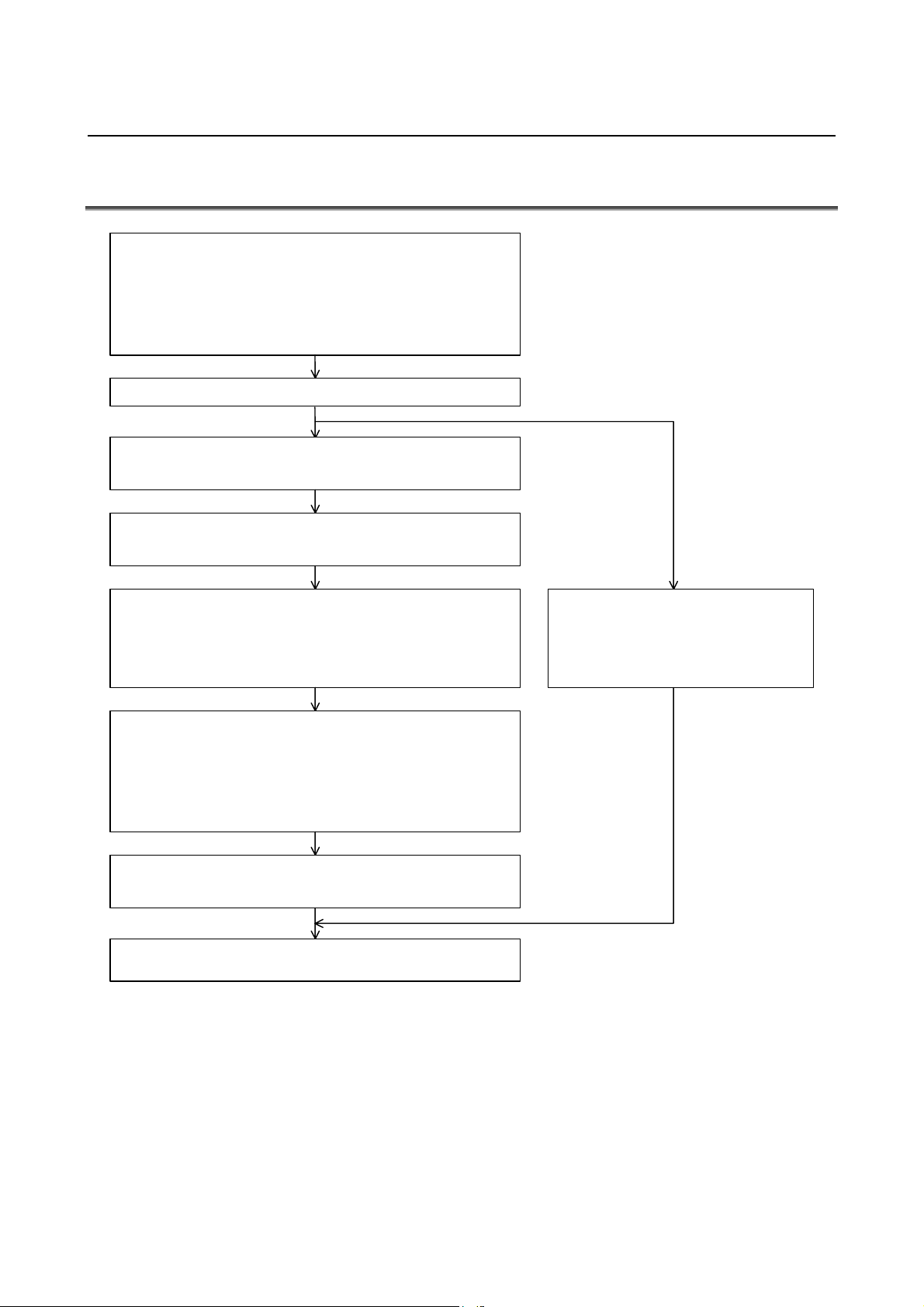
1.1 START-UP PROCEDURE
A. Check the spindle-related specifications.
- CNC model
- Spindle motor
- Power supply module
- Spindle amplifier module
- Detector system
B. Check all connections. (See DESCRIPTIONS (B-65272EN).)
C. Prepare and check the PMC ladder program.
D. Check the CNC parameter setting for using the αi series
(Serial) spindle. (See Subsection 1.2.1.)
E. Perform automatic αi series (Serial) spindle parameter
initialization. (See Subsection 1.2.2.)
- Set a motor model code and the parameter enabling use
of the automatic parameter initialization function, then turn
the CNC off and then on again.
F. Change parameter data (when no model code is used).
- For a motor for which there is no model code, perform
automatic initialization by specifying 300 (or 400 when the
speed range switching function is used), then change the
parameter data according to the parameter list for the
motor.
G. Set the parameters related to the detectors. (See Section 1.3.)
I. Check the waveforms of the feedback signals from detectors.
(Refer to the MAINTENANCE MANUAL (B-65285EN).)
H. When using a machine in a system
that has already been started, load all
CNC parameters for the machine.
- 4 -
Page 29

B-65280EN/05 FANUC AC SPINDLE MOTOR αi series 1.START-UP
1.2 SPINDLE SERIAL INTERFACE
1.2.1 Parameters Related to Spindle Serial Output
This subsection provides a list of the parameters related to spindle
serial output only. For details of each parameter, refer to the
Connection Manual (Function) of each CNC.
(a) For Series 16i/18i/21i
“FANUC Series 16i/18i/21i-MODEL B
CONNECTION MANUAL (FUNCTION) : B-63523EN-1
Refer to Section 9.2 “SPINDLE SERIAL OUTPUT/SPINDLE
ANALOG OUTPUT.”
(b) For Series 30i/31i/32i
“FANUC Series 30i/31i/32i-MODEL A
CONNECTION MANUAL (FUNCTION) : B-63943EN-1
Refer to Section 11.2 “SPINDLE SERIAL OUTPUT.”
(c) For Series 15i
“FANUC Series 15i-MODEL B
CONNECTION MANUAL (FUNCTION) : B-63783EN-1
Refer to Section 9.2 “SPINDLE SERIAL OUTPUT/SPINDLE
ANALOG OUTPUT.”
(d) For Series 0i
“FANUC Series 0i-MODEL C
CONNECTION MANUAL (FUNCTION) : B-64113EN-1
Refer to Section 9.2 “SPINDLE SERIAL OUTPUT/SPINDLE
ANALOG OUTPUT.”
Parameter No.
15i 16i 30i
3701#1
3716#0
5606#0
3701#4 Number of connectable serial spindles
3702#1 Multi-spindle control function
5841 Motor number of each spindle
3717 Amplifier number of each spindle
5845 3718 Spindle indication subscript (main spindle)
5846 3719 Spindle indication subscript (sub-spindle)
5850 Spindle number selected at power-on/reset time
Whether to use the serial interface
(Set 0.)
Selection of a spindle (analog/serial)
(Set 1.)
Selection of an interface (serial/analog)
(Set 1.)
(Whether to use the second serial spindle)
(Whether to use the multi-spindle control function)
NOTE
To use the spindle serial interface, the CNC software
option is required.
Description
Optional function
- 5 -
Page 30

1.START-UP FANUC AC SPINDLE MOTOR αi series B-65280EN/05
1.2.2 Automatic Spindle Parameter Initialization
(1) Parameter list
Parameter No.
15i 16i 30i
5607#0 4019#7 4019#7 Function for automatically initializing spindle parameters
3133 4133 4133 Spindle motor model code
(2) Procedure for automatic spindle parameter initialization
Perform automatic spindle parameter initialization by following the
procedure below.
<1> Set the model code for the desired motor for automatic parameter
initialization.
Parameter No.
15i 16i 30i
3133 4133 4133 Model code
NOTE
1 The control method usable with the αi series
spindle is spindle HRV control only. The
conventional control method is not supported.
2 When using a spindle motor that has no model
code, set model code "300" ("400" for a spindle
motor with speed range switching control) for
automatic parameter setting, then manually input
data according to the parameter table for each
motor model.
<2> Set the relevant parameter to enable automatic spindle parameter
initialization.
Parameter No.
15i 16i 30i
5607#0
NOTE
This bit is reset to its original value after
automatic parameter initialization.
<3> Turn the CNC off, then on again. Then, the spindle parameters
specified with a model code are automatically initialized.
4019#7 4019#7 1
Description
Description
Description
0
- 6 -
Page 31

B-65280EN/05 FANUC AC SPINDLE MOTOR αi series 1.START-UP
1.2.3 Diagnosis (Diagnosis Screen)
This subsection provides a list of the diagnosis (diagnosis screen)
indications related to spindle serial output only. For details, refer to
the Connection Manual (Function) of each CNC.
(a) For Series 16i/18i/21i
“FANUC Series 16i/18i/21i-MODEL B
CONNECTION MANUAL (FUNCTION) : B-63523EN-1
Refer to Section 9.2 “SPINDLE SERIAL OUTPUT/SPINDLE
ANALOG OUTPUT.”
(b) For Series 30i/31i/32i
“FANUC Series 30i/31i/32i-MODEL A
CONNECTION MANUAL (FUNCTION) : B-63943EN-1
Refer to Section 11.2 “SPINDLE SERIAL OUTPUT.”
(c) For Series 15i
“FANUC Series 15i-MODEL B
CONNECTION MANUAL (FUNCTION) : B-63783EN-1
Refer to Section 9.2 “SPINDLE SERIAL OUTPUT/SPINDLE
ANALOG OUTPUT.”
(d) For Series 0i
“FANUC Series 0i-MODEL C
CONNECTION MANUAL (FUNCTION) : B-64113EN-1
Refer to Section 9.2 “SPINDLE SERIAL OUTPUT/SPINDLE
ANALOG OUTPUT.”
(1) For Series 16i
Address Description
400 Information including spindle control
408 Information about spindle serial output interface communication errors
409 Information about spindle serial output interface activation
(2) For Series 30i
Address Description
400 Information including spindle control
408 Information about spindle serial output interface communication errors
(3) For Series 15i
Address Description
1500 Information about spindle serial output interface communication errors
- 7 -
Page 32

1.START-UP FANUC AC SPINDLE MOTOR αi series B-65280EN/05
1.2.4 Alarm
This subsection provides a list of the alarms related to spindle serial
output only. For details of each alarm, refer to the Connection Manual
(Function) of each CNC.
(a) For Series 16i/18i/21i
“FANUC Series 16i/18i/21i-MODEL B
CONNECTION MANUAL (FUNCTION) : B-63523EN-1
Refer to Section 9.2 “SPINDLE SERIAL OUTPUT/SPINDLE
ANALOG OUTPUT.”
(b) For Series 30i/31i/32i
“FANUC Series 30i/31i/32i-MODEL A
CONNECTION MANUAL (FUNCTION) : B-63943EN-1
Refer to Section 11.2 “SPINDLE SERIAL OUTPUT.”
(c) For Series 15i
“FANUC Series 15i-MODEL B
CONNECTION MANUAL (FUNCTION) : B-63783EN-1
Refer to Section 9.2 “SPINDLE SERIAL OUTPUT/SPINDLE
ANALOG OUTPUT.”
(d) For Series 0i
“FANUC Series 0i-MODEL C
CONNECTION MANUAL (FUNCTION) : B-64113EN-1
Refer to Section 9.2 “SPINDLE SERIAL OUTPUT/SPINDLE
ANALOG OUTPUT.”
(1) For Series 16i
Alarm No. Description
749 A serial communication error occurred while the system was being activated after power-on.
750 The (serial) spindle amplifier was not activated normally at power-on time.
(2) For Series 15i and Series 30i
Alarm No.
15i 30i
PS0223
SP0201 The same motor number other than 0 is set more than once in parameter No. 5841.
SP0202 A spindle number greater than the number of spindles is set in parameter No. 5850.
SP0220 SP1220
SP0221 The correspondence between spindle numbers and motor numbers is incorrect.
SP0225 SP1225
SP0226 SP1226 A framing error occurred in communication between the CNC and serial spindle amplifier.
SP0227 SP1227 A receive error occurred in communication between the CNC and serial spindle amplifier.
SP0228 SP1228
SP0229
SP1229
Before a spindle to be controlled is set correctly, a command for using the spindle was
executed.
The cable connected to the serial spindle amplifier is disconnected, or no serial spindle
amplifier is connected.
A CRC error (communication error) occurred in communication between the CNC and serial
spindle amplifier.
A communication error occurred in communication between the CNC and serial spindle
amplifier.
A communication error occurred in communication between serial spindle amplifiers (between
motor numbers 1 and 2 or between motor numbers 3 and 4).
A communication error occurred in communication between serial spindle amplifiers (between
an odd-numbered amplifier and even-numbered amplifier).
Description
- 8 -
Page 33

B-65280EN/05 FANUC AC SPINDLE MOTOR αi series 1.START-UP
Alarm No.
15i 30i
SP0230 The value set in parameter No. 5841 is not within the allowable range.
SP0970 Spindle control initialization was not terminated.
SP0976 No amplifier number could be set for a serial spindle amplifier.
SP0978 A time-out was detected in communication with a serial spindle amplifier.
SP0979 The communication sequence was incorrect in communication with a serial spindle amplifier.
SP0980
SP0981 An error occurred when data was written to the SIC-LSI on the serial spindle amplifier side.
SP0982 An error occurred when data was read from the SIC-LSI on the serial spindle amplifier side.
SP0983 An alarm on the spindle amplifier side could not be cleared.
SP0984 An error occurred during spindle amplifier reinitialization.
SP0985 Automatic parameter setting failed.
SP0987
SP0996 The assignment of spindles and spindle motors is incorrect.
SP1996
SP1980 to
SP1984
SP1985 to
SP1987
SP1245 to
SP1247
SP1976 to
SP1979
SP1988 to
SP1989
The SIC-LSI on the serial spindle amplifier side is faulty.
The SIC-LSI on the CNC side is faulty.
A communication data error was detected on the CNC side.
An error occurred with the spindle control software.
An error occurred with the spindle control software.
Spindle motor assignment is incorrect. Check the parameters indicated hereafter.
(No.3716,No.3717)
Description
- 9 -
Page 34

1.START-UP FANUC AC SPINDLE MOTOR αi series B-65280EN/05
1.3 PARAMETERS RELATED TO DETECTORS
NOTE
1 Note that the specifications of parameters related
to detectors for the αi series spindle amplifiers
differ from those of parameters for the α series
spindle amplifiers.
2 The terms "motor sensor" and "spindle sensor"
used in the text mean the speed/position detectors
connected to the connectors described below.
(i) Motor sensor :
Detector connected to connector JYA2
(Mi sensor, MZi sensor, BZi sensor of a built-in
motor, CZi sensor of a built-in motor)
(ii) Spindle sensor :
Detector connected to connector JYA3 or JYA4
(α position coder, α position coder S, separate
BZi sensor, separate CZi sensor, and so forth)
1.3.1 List of Parameters for Detectors
Parameter No.
15i 16i 30i
3706#1,0 Gear ratio of spindle to position coder (×1, ×2, ×4, ×8)
5842 3720 Number of pulses of the position coder
3000#0 4000#0 4000#0 Direction of spindle and spindle motor rotation
3001#4 4001#4 4001#4 Spindle sensor mounting direction
3002#3,2,1,0 4002#3,2,1,0 4002#3,2,1,0 Spindle sensor type setting
3003#7,6,5,4 4003#7,6,5,4 4003#7,6,5,4 Setting of the number of spindle sensor gear teeth
3004#3,2 4004#3,2 4004#3,2 External one-rotation signal (proximity switch) setting
3006#1 4006#1 4006#1 Gear ratio increment system
3007#5 4007#5 4007#5 Whether to detect disconnection of feedback signals
3007#6 4007#6 4007#6
3010#2,1,0 4010#2,1,0 4010#2,1,0 Motor sensor type setting
3011#2,1,0 4011#2,1,0 4011#2,1,0 Setting of the number of motor sensor gear teeth
3016#5 4016#5 4016#5
3016#6 4016#6 4016#6 Whether to detect alarms related to threading feedback
3016#7 4016#7 4016#7
3394#2 4394#2 4394#2 Setting of the detection lower limit of the one-rotation signal
3394#5 4394#5 4394#5
3056 to 3059 4056 to 4059 4056 to 4059
3098 4098 4098 Maximum speed for position feedback signal detection
Whether to detect alarms related to position feedback signals (on
non-Cs contouring control mode)
Whether to detect alarms related to position feedback (in Cs
contouring control mode)
Setting of the function of detecting the one-rotation signal again
each time position control mode is set.
Whether to detect the alarm related to spindle sensor polarity
erroneous setting
Spindle-to-motor gear ratio data (This data is selected by spindle
control input signals CTH1A and CTH2A.)
Description
- 10 -
Page 35

B-65280EN/05 FANUC AC SPINDLE MOTOR αi series 1.START-UP
Parameter No.
3171
3173
3172
3174
3334 4334 4334 Arbitrary number of motor sensor teeth
3355 4355 4355 Motor sensor signal amplitude ratio compensation
3356 4356 4356 Motor sensor signal phase difference compensation
3357 4357 4357 Spindle sensor signal amplitude ratio compensation
3358 4358 4358 Spindle sensor signal phase difference compensation
3361 4361 4361 Arbitrary number of spindle sensor teeth
3500
3502
3501
3503
4171
4173
4172
4174
4500
4502
4501
4503
4171
4173
4172
4174
4500
4502
4501
4503
Denominator of arbitrary gear ratio between motor sensor and
spindle
(This data is selected by spindle control input signal CTH1A.)
Numerator of arbitrary gear ratio between motor sensor and
spindle
(This data is selected by spindle control input signal CTH1A.)
Denominator of arbitrary gear ratio between spindle sensor and
spindle
(This data is selected by spindle control input signal CTH1A.)
Numerator of arbitrary gear ratio between spindle sensor and
spindle
(This data is selected by spindle control input signal CTH1A.)
- 11 -
Page 36

1.START-UP FANUC AC SPINDLE MOTOR αi series B-65280EN/05
1.3.2 Details of Parameters for Detectors
This subsection details the serial spindle parameters (in the four
thousands for 16i, and in the four thousands for 30i, and in the three
thousands for 15i) among the detector-related parameters. For details
of other parameters, refer to the Connection Manual (Function) of
each CNC.
(a) For Series 16i/18i/21i
“FANUC Series 16i/18i/21i-MODEL B
CONNECTION MANUAL (FUNCTION) : B-63523EN-1
Refer to Section 9.3 “SPINDLE SPEED CONTROL.”
(b) For Series 30i/31i/32i
“FANUC Series 30i/31i/32i-MODEL A
CONNECTION MANUAL (FUNCTION) : B-63943EN-1
Refer to Section 11.3 “SPINDLE SPEED CONTROL.”
(c) For Series 15i
“FANUC Series 15i-MODEL B
CONNECTION MANUAL (FUNCTION) : B-63783EN-1
Refer to Section 9.3 “SPINDLE SPEED CONTROL.”
(d) For Series 0i
“FANUC Series 0i-MODEL C
CONNECTION MANUAL (FUNCTION) : B-64113EN-1
Refer to Section 9.3 “SPINDLE SPEED CONTROL.”
3000 4000 4000
3001 4001 4001
3002 4002 4002
SSTYP3 to SSTYP0 Spindle sensor type
15i 16i 30i
#7 #6 #5 #4 #3 #2 #1 #0
ROTA1
ROTA1 Indicates the relationship between the rotation directions of spindle
and spindle motor.
0 : Rotates the spindle and spindle motor in the same direction.
1 : Rotates the spindle and spindle motor in the reverse direction.
15i 16i 30i
#7 #6 #5 #4 #3 #2 #1 #0
SSDIRC
SSDIRC Indicates the mounting direction of spindle sensor.
0 : Rotates the spindle and spindle sensor in the same direction.
1 : Rotates the spindle and spindle sensor in the reverse direction.
15i 16i 30i
#7 #6 #5 #4 #3 #2 #1 #0
SSTYP3 SSTYP2 SSTYP1 SSTYP0
This parameter sets the type of a separate detector to be attached to the
spindle (detector to be connected to connector JYA3 or JYA4).
- 12 -
Page 37

B-65280EN/05 FANUC AC SPINDLE MOTOR αi series 1.START-UP
SSTYP3 SSTYP2 SSTYP1 SSTYP0 Spindle sensor type
0 0 0 0 None (No position control function is used.)
0 0 0 1 Uses the motor sensor for position feedback
0 0 1 0 α position coder
0 0 1 1
0 1 0 0 α position coder S
Separate BZi sensor, CZi sensor
NOTE
When using a rectangular wave phase A/B,
1024-p/rev position coder, set the same settings as
for the α position coder (0,0,1,0).
3003 4003 4003
15i 16i 30i
#7 #6 #5 #4 #3 #2 #1 #0
PCPL2 PCPL1 PCPL0 PCTYPE
PCPL2, PCPL1, PCPL0, PCTYPE Gear teeth number setting of the spindle sensor
This parameter sets the number of teeth of a separate detector to be
attached to the spindle (detector to be connected to connector JYA3 or
JYA4).
PCPL2 PCPL1 PCPL0 PCTYPE
0 0 0 0 256λ/rev
0 0 0 1 128λ/rev
0 1 0 0 512λ/rev
0 1 0 1 64λ/rev
1 0 0 0 768λ/rev
1 0 0 1 1024λ/rev
1 1 0 0 384λ/rev
Gear teeth number of
the spindle sensor
NOTE
1 Set "0, 0, 0, 0" when using an α position coder (bits
3, 2, 1, 0 of No. 4002 = 0, 0, 1, 0) or an α position
coder S (bits 3, 2, 1, 0 of No. 4002 = 0, 1, 0, 0).
2 When the motor sensor is used for position
feedback (bits 3, 2, 1, 0 of No. 4002 = 0, 0, 0, 1),
this parameter need not be set.
3004 4004 4004
15i 16i 30i
#7 #6 #5 #4 #3 #2 #1 #0
RFTYPE EXTRF
EXTRF, RFTYPE External one-rotation signal setting
This parameter sets the type of an external one-rotation signal
(proximity) switch to be attached to the spindle (to be connected to
connector JYA3).
RFTYPE EXTRF
0 0 None
0 1 Detects the leading edge.
1 1 Detects the trailing edge.
External one-rotation signal
(proximity switch)
- 13 -
Page 38

1.START-UP FANUC AC SPINDLE MOTOR αi series B-65280EN/05
3006 4006 4006
15i 16i 30i
#7 #6 #5 #4 #3 #2 #1 #0
GRUNIT
GRUNIT Sets a gear ratio setting resolution:
0 : 1/100 unit
1 : 1/1000 unit
Select a gear ratio data setting resolution from the following:
(a) Resolution based on motor rotation increased by a factor of 100
relative to one spindle rotation
(b) Resolution based on motor rotation increased by a factor of 1000
relative to one spindle rotation
Depending on the setting of this parameter, the increment system of
the parameters indicated in the table below changes.
Parameter No.
15i 16i 30i
3056 to 3059 4056 to 4059 4056 to 4059 Spindle-to-motor gear ratio data
Description
NOTE
Usually, use the 1/100 unit (setting "0").
3007 4007 4007
15i 16i 30i
#7 #6 #5 #4 #3 #2 #1 #0
PCALCH PCLS
PCLS Determines feedback signal disconnection detection.
0 : Performs disconnection detection.
1 : Does not perform disconnection detection.
When this bit is set to "0", SPM alarms 27 (Position coder signal
disconnection), 73 (Motor sensor disconnection), and 84 (Spindle
sensor disconnection) are checked.
NOTE
1 Usually, set “0”.
2 When adjusting the waveform of a motor/spindle
sensor feedback signal, set "1" temporarily to
disable disconnection detection. After completion
of adjustment, be sure to return the setting to
"0" to enable disconnection detection.
PCALCH Determines whether to use alarms related to position feedback signals
(on non-Cs contouring control mode).
0 : Detects alarms.
1 : Does not detect alarms.
When this bit is set to "0", SPM alarms 41, 42, 47, 81, 82, 83, 85, 86,
and 87 are checked.
- 14 -
Page 39

B-65280EN/05 FANUC AC SPINDLE MOTOR αi series 1.START-UP
3010 4010 4010
15i 16i 30i
#7 #6 #5 #4 #3 #2 #1 #0
MSTYP2 MSTYP1 MSTYP0
MSTYP2, MSTYP1, MSTYP0 Motor sensor type
This parameter sets the type of a detector built into the motor (detector
to be connected to JYA2).
MSTYP2 MSTYP1 MSTYP0 Motor sensor type
0 0 0
0 0 1
Mi sensor
MZi, BZi, CZi sensor
3011 4011 4011
15i 16i 30i
#7 #6 #5 #4 #3 #2 #1 #0
VDT3 VDT2 VDT1
VDT1 to VDT3 Gear teeth number setting of the motor sensor
This parameter sets the number of teeth of a detector built into the
motor (detector to be connected to JYA2).
VDT3 VDT2 VDT1 Gear teeth number of the motor sensor
0 0 0 64λ/rev
0 0 1 128λ/rev
0 1 0 256λ/rev
0 1 1 512λ/rev
1 0 0 192λ/rev
1 0 1 384λ/rev
NOTE
When using a sensor with CZi sensor 768 λ/rev or
1024 λ/rev, set 0,0,0 in this parameter, and set 768
or 1024 in the parameter specifying an arbitrary
number of motor sensor teeth (parameter No.
4334).
Motor models and corresponding Mi and MZi sensors
Number of gear teeth of the detection
ring on the Mi or MZi sensor
64λ/rev
128λ/rev
256λ/rev
3016 4016 4016
15i 16i 30i
#7 #6 #5 #4 #3 #2 #1 #0
RFCHK3 RFCHK2 RFCHK1
RFCHK1 Determines whether to detect alarms related to position feedback (in
Cs contouring control mode).
0 : Does not detect alarms.
1 : Detects alarms.
When this bit is set to "1", SPM alarms 81, 82, 85, and 86 are
checked.
Motor model
α0.5i
α1i to α3i
α6i to α50i
α12i
P to α60iP
- 15 -
Page 40

1.START-UP FANUC AC SPINDLE MOTOR αi series B-65280EN/05
RFCHK2 Determines whether to detect the alarm related to threading position
detection signal feedback (SPM alarm 46).
0 : Does not detect alarms.
1 : Detects alarms.
RFCHK3 Setting of the function of detecting the one-rotation signal again each
time position control mode is set.
0 : The one-rotation signal is not detected each time the operating
mode changes.
Once the one-rotation signal has been detected, it is not detected
again until the power goes off.
1 : The one-rotation signal is detected each time the operating mode
changes.
3394 4394 4394
15i 16i 30i
#7 #6 #5 #4 #3 #2 #1 #0
A21DEN ZPHDTC
ZPHDTC Sets the detection lower limit of the one-rotation signal.
0 : The one-rotation signal is detected when the spindle speed is 10
min
-1
or more.
1 : The one-rotation signal is detected regardless of the spindle
speed.
NOTE
1 This parameter is valid with 9D50 Series E (05)
edition or later and 9D70 series A (01) edition or
later.
2 This parameter is enabled when the spindle sensor
is an α position coder or α position coder S.
When the spindle sensor is the MZi/BZi/CZi sensor,
-1
if the spindle speed is 10 min
or more, the
one-rotation signal is detected regardless of the
setting of this parameter.
A21DEN Whether to detect the spindle sensor polarity erroneous setting alarm
(SPM alarm 21).
0 : The spindle sensor polarity erroneous setting alarm is detected.
1 : The spindle sensor polarity erroneous setting alarm is not
detected.
When the spindle sensor polarity erroneous setting alarm is incorrectly
detected due to the following reasons, set this bit to disable the alarm
detection.
- When the spindle is mechanically separated from the motor.
- When the belt between the spindle and the motor slips.
NOTE
This parameter is valid with 9D50 Series E (05)
edition or later and 9D70 series A (01) edition or
later.
- 16 -
Page 41

B-65280EN/05 FANUC AC SPINDLE MOTOR αi series 1.START-UP
3056 4056 4056
3057 4057 4057
15i 16i 30i
3058 4058 4058
3059 4059 4059
Gear ratio (HIGH) CTH1A=0, CTH2A=0
Gear ratio (MEDIUM HIGH) CTH1A=0, CTH2A=1
Gear ratio (MEDIUM LOW) CTH1A=1, CTH2A=0
Gear ratio (LOW) CTH1A=1, CTH2A=1
Unit of data : (Motor rotation for one rotation of spindle) / 100
(When parameter No. 4006 #1 (GRUNIT) is 1, motor rotation / 1000)
Valid data range : 0 to 32767
Standard setting : 100
These data are used to set the gear ratio between spindle and spindle
motor.
Example :
When the spindle rotates once, set "250" as the data when the
motor rotates 2.5 times.
A parameter is selected with the CTH1A and CTH2A input signals.
Set the gear or clutch status to correspond to the clutch/gear signal
(CTH1A, CTH2A).
NOTE
When an improper value is set in these parameters,
an unexpected operation can occur. For example,
the spindle can continue rotating without stopping at
the time of orientation. So, be sure to set a proper
gear ratio.
3098 4098 4098
15i 16i 30i
Maximum speed for position feedback signal detection
Unit of data : 1min
-1
(Unit of 10 min-1 when bit 2 (SPDUNT) of parameter No. 4006
= 1)
Valid data range : 0 to 32767
Standard setting : 0
This parameter sets a maximum spindle speed that enables the
detection of a motor/spindle sensor feedback signal.
When "0" is set in this parameter, up to the maximum motor speed can
be detected.
NOTE
Usually, set “0”.
- 17 -
Page 42

1.START-UP FANUC AC SPINDLE MOTOR αi series B-65280EN/05
3171 4171 4171
15i 16i 30i
3172 4172 4172
3173 4173 4173
3174 4174 4174
Denominator of arbitrary gear ratio between motor sensor and spindle (HIGH)
CTH1A=0
Numerator of arbitrary gear ratio between motor sensor and spindle (HIGH)
CTH1A=0
Denominator of arbitrary gear ratio between motor sensor and spindle (LOW)
CTH1A=1
Numerator of arbitrary gear ratio between motor sensor and spindle (LOW)
CTH1A=1
Unit of data :
Valid data range : 0 to 32767
Standard setting : 0
These parameters set conversion coefficients (numerator,
denominator) for using the detection arbitrary gear ratio function
(DMR function) by multiplying a motor sensor (Mi or MZi sensor)
feedback signal by a gear ratio to produce a spindle position feedback
signal.
When the spindle rotates Q times while the motor shaft rotates P times
(there is no common divisor other than 1 for P and Q), settings are:
No. 4171 (No. 4173 when CTH1A = 1) = P
No. 4172 (No. 4174 when CTH1A = 1) = Q
When one of these parameters is set to "0", it is assumed to be "1".
NOTE
When using the external one-rotation signal
(proximity switch), use the detection arbitrary gear
ratio function (DMR function) by setting an arbitrary
gear ratio between the motor sensor and spindle in
this parameter.
3334 4334 4334
15i 16i 30i
Arbitrary number of motor sensor teeth
Unit of data : 1λ/rev (Number of motor sensor teeth)
Valid data range : 0, 32 to 4096
Standard setting : 0
When the number of motor sensor teeth is other than 64, 128, 192, 256,
384, and 512, set this parameter.
When "0" is set in this parameter, the setting of bits 2, 1, 0 (VDT3,
VDT2, VDT1) of parameter No. 4011 is valid.
- 18 -
Page 43

B-65280EN/05 FANUC AC SPINDLE MOTOR αi series 1.START-UP
3355 4355 4355
3357 4357 4357
15i 16i 30i
Motor sensor signal amplitude ratio compensation
Spindle sensor signal amplitude ratio compensation
Unit of data : 1%
Valid data range : -8 to 8
Standard setting : 0
These parameters set an amplitude ratio compensation value for the
sensor feedback signal (phase A/B of the sinusoidal wave).
For details, refer to the Section I-4.3 “AMPLITUDE RATIO/PHASE
DIFFERENCE COMPENSATION FUNCTION.”
3356 4356 4356
3358 4358 4358
15i 16i 30i
Motor sensor signal phase difference compensation
Spindle sensor signal phase difference compensation
Unit of data : 1%
Valid data range : -4 to 4
Standard setting : 0
These parameters set a phase difference compensation value for the
sensor signal (phase A/B of the sinusoidal wave).
For details, refer to the Section I-4.3 “AMPLITUDE RATIO/PHASE
DIFFERENCE COMPENSATION FUNCTION.”
3361 4361 4361
15i 16i 30i
Arbitrary number of spindle sensor teeth
Unit of data : 1λ/rev (Number of spindle sensor teeth)
Valid data range : 0, 64 to 4096
Standard setting : 0
When the number of spindle sensor teeth is other than 64, 128, 256,
384, 512, and 1024 set this parameter.
When "0" is set in this parameter, the setting of bits 7, 6, 5, 4 (PCPL2,
PCPL1, PCPL0, PCTYPE) of parameter No. 4003 is valid.
- 19 -
Page 44

1.START-UP FANUC AC SPINDLE MOTOR αi series B-65280EN/05
3500 4500
3501 4501
3502 4502
3503 4503
15i 16i
Denominator of arbitrary gear ratio between spindle sensor and spindle
(HIGH) CTH1A=0
Numerator of arbitrary gear ratio between spindle sensor and spindle (HIGH)
CTH1A=0
Denominator of arbitrary gear ratio between spindle sensor and spindle
(LOW) CTH1A=1
Numerator of arbitrary gear ratio between spindle sensor and spindle (LOW)
CTH1A=1
Unit of data :
Valid data range : 0 to 32767
Standard setting : 0
These parameters set conversion coefficients (numerator,
denominator) for using the detection arbitrary gear ratio function
(DMR function) by multiplying a spindle sensor (α position coder, α
position coder S, separate BZi sensor, or separate CZi sensor)
feedback signal by a gear ratio to produce a spindle position feedback
signal.
When the spindle rotates Q times while the motor shaft rotates P times
(there is no common divisor other than 1 for P and Q), settings are:
No. 4500 (No. 4502 when CTH1A = 1) = P
No. 4501 (No. 4503 when CTH1A = 1) = Q
When one of these parameters is set to "0", it is assumed to be "1".
NOTE
1 This parameter is valid with 9D50 Series F (06)
edition or later and 9D70 series A (01) edition or
later.
2 When this parameter is used in a configuration
having no external one-rotation signal (proximity
switch), set the following parameters.
No.4007#6=1 : Alarms related to positional
feedback signals (in non-Cs mode)
are not detected.
No.4016#5=0 : Alarms related to positional
feedback signals (in Cs mode) are
not detected.
- 20 -
Page 45

B-65280EN/05 FANUC AC SPINDLE MOTOR αi series 1.START-UP
1.3.3 Typical Detector Configurations
This subsection describes typical detector configurations and the
parameter setting procedures for the detector configurations.
With the αi series spindle, the detector circuitry hardware is set
according to the parameter setting. For this reason, an alarm such as a
disconnection alarm may be output while parameters related to
detectors are being set.
To initialize the hardware, after setting the parameters related to
detectors, turn the power to the amplifier off once.
(1) When position control is not exercised
[Sample system configuration]
Spindle motor with built-in Mi sensor
JYA2
SPM
TYPE A
Spindle
Parameter No. Settings Description
4002 #3,2,1,0 0,0,0,0 Does not exercise position control.
4010 #2,1,0
4011 #2,1,0
Depends on the
detector.
Depends on the
detector.
Sets the type of motor sensor.
Sets the number of motor sensor gear
teeth.
- 21 -
Page 46

1.START-UP FANUC AC SPINDLE MOTOR αi series B-65280EN/05
α
(2) When the α position coder is used
[Sample system configuration]
Spindle motor with built-in Mi sensor
(or MZi sensor)
JYA2
position coder
SPM
TYPE A
JYA3
Directly connected or connected with a gear or timing
belt at a ratio of 1:1
Spindle
Parameter No. Settings Description
4000 #0
4001 #4
4002 #3,2,1,0 0,0,1,0
4003 #7,6,5,4 0,0,0,0
4010 #2,1,0
4011 #2,1,0
4056 to 4059
Depends on the
configuration.
Depends on the
configuration.
Depends on the
detector.
Depends on the
detector.
Depends on the
configuration.
Rotation directions of the spindle and
motor
Spindle sensor mounting direction
Uses the α position coder as the
spindle sensor.
Sets the number of spindle sensor
gear teeth.
Sets the type of motor sensor.
Sets the number of motor sensor gear
teeth.
Gear ratio between the spindle and
motor
- 22 -
Page 47

B-65280EN/05 FANUC AC SPINDLE MOTOR αi series 1.START-UP
α
t
(3) When the α position coder S is used
[Sample system configuration]
Spindle motor with built-in Mi sensor
(or MZi sensor)
JYA2
position coder S
SPM
TYPE B
JYA4
Directly connected or connected with a gear or timing bel
at a ratio of 1:1
Spindle
Parameter No. Settings Description
4000 #0
4001 #4
4002 #3,2,1,0 0,1,0,0
4003 #7,6,5,4 0,0,0,0
4010 #2,1,0
4011 #2,1,0
4056 to 4059
Depends on the
configuration.
Depends on the
configuration.
Depends on the
detector.
Depends on the
detector.
Depends on the
configuration.
Rotation directions of the spindle and
motor
Spindle sensor mounting direction
Uses the α position coder S as the
spindle sensor.
Sets the number of spindle sensor
gear teeth.
Sets the type of motor sensor.
Sets the number of motor sensor gear
teeth.
Gear ratio between the spindle and
motor
- 23 -
Page 48

1.START-UP FANUC AC SPINDLE MOTOR αi series B-65280EN/05
(4) When the MZi, BZi, or CZi sensor is used
[Sample system configuration 1]
Spindle motor with built-in MZi sensor
Spindle
[Sample system configuration 2]
BZi sensor or CZi sensor
Spindle +
built-in motor
[Sample system configuration 3]
Spindle motor with built-in MZi sensor
Spindle
Directly connected or connected with a gear or timing belt
at a ratio of 1:1
Parameter
No.
4000 #0 0 Rotation directions of the spindle and motor
4002 #3,2,1,0 0,0,0,1
4010 #2,1,0 0,0,1
4011 #2,1,0
4056 to 4059 100 or 1000
Settings Description
Uses the motor sensor for position
feedback.
Uses the MZi , BZi, or CZi sensor as the
motor sensor.
Depends on
the detector.
Sets the number of motor sensor gear teeth.
Gear ratio between the spindle and motor
1 : 1
- 24 -
Page 49

B-65280EN/05 FANUC AC SPINDLE MOTOR αi series 1.START-UP
(5) When the separate type BZi sensor or separate type CZi sensor is used
[Sample system configuration]
Parameter No. Settings Description
4000 #0
4001 #4
4002 #3,2,1,0 0,0,1,1
4003 #7,6,5,4
4010 #2,1,0
4011 #2,1,0
4056 to 4059
Depends on the
configuration.
Depends on the
configuration.
Depends on the
detector.
Depends on the
detector.
Depends on the
detector.
Depends on the
configuration.
Spindle motor with built-in Mi sensor
(or MZi sensor)
Spindle
BZi sensor or CZi sensor
Rotation directions of the spindle and
motor
Spindle sensor mounting direction
Uses the BZi sensor or CZi sensor as
the spindle sensor.
Sets the number of spindle sensor
gear teeth.
Sets the type of motor sensor.
Sets the number of motor sensor gear
teeth.
Gear ratio between the spindle and
motor
- 25 -
Page 50

1.START-UP FANUC AC SPINDLE MOTOR αi series B-65280EN/05
(6) When the external one-rotation signal (proximity switch) is used
[Sample system configuration]
Spindle motor with built-in Mi sensor
(or MZi sensor)
Spindle
External one-rotation
signal (proximity switch)
Gear or timing belt
Parameter No. Settings Description
4000 #0
4002 #3,2,1,0 0,0,0,1
4004 #2 1 Uses the external one-rotation signal.
4004 #3
4010 #2,1,0
4011 #2,1,0
4056 to 4059
4171 to 4174
Depends on the
configuration.
Depends on the
detector.
Depends on the
detector.
Depends on the
detector.
Depends on the
configuration.
Depends on the
configuration.
Rotation directions of the spindle and
motor
Uses the motor sensor for position
feedback.
Sets the external one-rotation signal
type.
Sets the type of motor sensor.
Sets the number of motor sensor gear
teeth.
Gear ratio between the spindle and
motor
Arbitrary gear ratio between the motor
sensor and spindle
- 26 -
Page 51

B-65280EN/05 FANUC AC SPINDLE MOTOR αi series 1.START-UP
α
(7) When the axis on which the spindle sensor is mounted is not the spindle
[Sample system configuration]
Spindle motor with built-in Mi
sensor
Gear or
timing belt
JYA2
SPM
position coder
Medial
axis
TYPE A
JYA3
Directly connected or connected
Spindle
with a gear or timing belt at a
ratio of 1:1
Parameter No. Settings Description
4000 #0
4001 #4
4002 #3,2,1,0
4003 #7,6,5,4
4010 #2,1,0 0, 0, 0
4011 #2,1,0
4007 #6 1
4016 #5 0
4056 to 4059
4500 to 4503
Depends on the
configuration.
Depends on the
configuration.
Depends on the
configuration.
Depends on the
detector.
Depends on the
detector.
Depends on the
configuration.
Depends on the
configuration.
Rotation directions of the spindle and
motor
Spindle sensor mounting direction
Type of spindle sensor
Sets the number of spindle sensor gear
teeth.
Uses the Mi sensor as the motor
sensor.
Sets the number of motor sensor gear
teeth.
Alarms related to positional feedback
signals (in non-Cs mode) are not
detected.
Alarms related to positional feedback
signals (in Cs mode) are not detected.
Gear ratio between the spindle and
motor
Arbitrary gear ratio between the spindle
sensor and spindle
NOTE
Those functions such as the orientation function that
require a one-rotation signal cannot be used.
- 27 -
Page 52

2.EXPLANATION OF OPERATION MODES FANUC AC SPINDLE MOTOR αi series B-65280EN/05
2 EXPLANATION OF OPERATION MODES
- 28 -
Page 53

B-65280EN/05 FANUC AC SPINDLE MOTOR αi series 2.EXPLANATION OF OPERATION MODES
2.1 VELOCITY CONTROL MODE
2.1.1 Start-up Procedure
A. Check that the serial spindle starts up normally and is ready for
operation.
B. Prepare and check the PMC ladder.
C. Set the detector-related parameters according to the system
configuration.
D. Set the parameters related to spindle speed specification.
E. Check that the spindle rotates at the desired speed.
F. Make a velocity loop gain adjustment as required.
• No.4040, 4041 : Velocity loop proportional gain
• No.4048, 4049 : Velocity loop integral gain
2.1.2 Overview
The velocity control mode is a function for exercising velocity control
to rotate the spindle motor according to a velocity command from the
CNC.
NOTE
On a CNC screen (such as the spindle monitor
screen and the adjustment screen), the velocity
control mode is indicated as "NORMAL
OPERATION MODE".
2.1.3 System Configuration
The velocity control mode is applicable to all detector configurations.
For system configurations, see Subsection 1.3.3, "TYPICAL
DETECTOR CONFIGURATIONS".
- 29 -
Page 54

2.EXPLANATION OF OPERATION MODES FANUC AC SPINDLE MOTOR αi series B-65280EN/05
2.1.4 List of I/O Signals (CNC↔PMC)
This subsection provides a list of the I/O signals related to the velocity
control mode only. For details of each signal, refer to the Connection
Manual (Function) of each CNC.
(a) For Series 16i/18i/21i
“FANUC Series 16i/18i/21i-MODEL B
CONNECTION MANUAL (FUNCTION) : B-63523EN-1
Refer to Section 9.3 “SPINDLE SPEED CONTROL.”
(b) For Series 30i/31i/32i
“FANUC Series 30i/31i/32i-MODEL A
CONNECTION MANUAL (FUNCTION) : B-63943EN-1
Refer to Section 11.3 “SPINDLE SPEED CONTROL.”
(c) For Series 15i
“FANUC Series 15i-MODEL B
CONNECTION MANUAL (FUNCTION) : B-63783EN-1
Refer to Section 9.3 “SPINDLE SPEED CONTROL.”
(d) For Series 0i
“FANUC Series 0i-MODEL C
CONNECTION MANUAL (FUNCTION) : B-64113EN-1
Refer to Section 9.3 “SPINDLE SPEED CONTROL.”
For details of the I/O signals common to the CNCs, see Chapter 3,
"I/O SIGNALS (CNC ↔ PMC)", in Part I.
(1) Input signals(PMC→CNC)
(a) Series 16i
#7 #6 #5 #4 #3 #2 #1 #0
Common to all axes G027 *SSTP2
Common to all axes G028 GR2 GR1
Common to all axes G029 *SSTP SOR SAR
Common to all axes G030 SOV7 SOV6 SOV5 SOV4 SOV3 SOV2 SOV1 SOV0
1st- G032 R08I R07I R06I R05I R04I R03I R02I R01I
2nd- G034 R08I2 R07I2 R06I2 R05I2 R04I2 R03I2 R02I2 R01I2
1st- G033 SIND SSIN SGN R12I R11I R10I R09I
2nd- G035 SIND2 SSIN2 SGN2 R12I2 R11I2 R10I2 R09I2
(*1)
NOTE
*1 These signals are valid in multi-spindle control.
*SSTP1
(*1)
SWS2
(*1)
SWS1
(*1)
- 30 -
Page 55

B-65280EN/05 FANUC AC SPINDLE MOTOR αi series 2.EXPLANATION OF OPERATION MODES
(b) Series 30i
#7 #6 #5 #4 #3 #2 #1 #0
Common to all axes G027 *SSTP2
Common to all axes G028 GR2 GR1
Common to all axes G029 *SSTP SOR SAR
Common to all axes G030 SOV7 SOV6 SOV5 SOV4 SOV3 SOV2 SOV1 SOV0
1st- G032 R08I R07I R06I R05I R04I R03I R02I R01I
2nd- G034 R08I2 R07I2 R06I2 R05I2 R04I2 R03I2 R02I2 R01I2
1st- G033 SIND SSIN SGN R12I R11I R10I R09I
2nd- G035 SIND2 SSIN2 SGN2 R12I2 R11I2 R10I2 R09I2
(*1)
*SSTP1
(*1)
SWS2
(*1)
SWS1
(*1)
NOTE
*1 These signals are valid in multi-spindle control.
(c) Series 15i
Common to all axes G005 FIN
1st- G024 RI7A RI6A RI5A RI4A RI3A RI2A RI1A RI0A
2nd- G232 RI7B RI6B RI5B RI4B RI3B RI2B RI1B RI0B
1st- G025 RISGNA RI12A RI11A RI10A RI9A RI8A
2nd- G233 RISGNB RI12B RI11B RI10B RI9B RI8B
1st- G026 GS4A GS2A GS1A
2nd- G272 GS4B GS2B GS1B
#7 #6 #5 #4 #3 #2 #1 #0
(d) Common to CNCs
1st- G227 G070 G070 MRDYA SFRA SRVA CTH1A CTH2A TLMHA TLMLA
2nd- G235 G074 G074 MRDYB SFRB SRVB CTH1B CTH2B TLMHB TLMLB
1st- G226 G071 G071 SOCNA *ESPA
2nd- G234 G075 G075 SOCNB *ESPB
1st- G229 G072 G072 OVRA
2nd- G237 G076 G076 OVRB
15i 16i 30i
#7 #6 #5 #4 #3 #2 #1 #0
- 31 -
Page 56

2.EXPLANATION OF OPERATION MODES FANUC AC SPINDLE MOTOR αi series B-65280EN/05
(2) Output signals (CNC→PMC)
(a) Series 16i
F001 ENB
F007 SF
F022 S07 S06 S05 S04 S03 S02 S01 S00
F023 S15 S14 S13 S12 S11 S10 S09 S08
F024 S23 S22 S21 S20 S19 S18 S17 S16
F025 S31 S30 S29 S28 S27 S26 S25 S24
F034 GR3O
F036 R08O R07O R06O R05O R04O R03O R02O R01O
F037 R12O R11O R10O R09O
(b) Series 16i
F001 ENB
F007 SF
F022 S07 S06 S05 S04 S03 S02 S01 S00
F023 S15 S14 S13 S12 S11 S10 S09 S08
F024 S23 S22 S21 S20 S19 S18 S17 S16
F025 S31 S30 S29 S28 S27 S26 S25 S24
F034 GR3O
F036 R08O R07O R06O R05O R04O R03O R02O R01O
F037 R12O R11O R10O R09O
#7 #6 #5 #4 #3 #2 #1 #0
(*1)
GR2O
(*1)
NOTE
*1 These signals are valid with the M series only.
#7 #6 #5 #4 #3 #2 #1 #0
(*1)
GR2O
(*1)
NOTE
*1 These signals are valid with the M series only.
GR1O
(*1)
GR1O
(*1)
- 32 -
Page 57

B-65280EN/05 FANUC AC SPINDLE MOTOR αi series 2.EXPLANATION OF OPERATION MODES
(b) Series 15i
Common to all axes F008 SF
Common to all axes F020 S7 S6 S5 S4 S3 S2 S1 S0
Common to all axes F021 S15 S14 S13 S12 S11 S10 S09 S08
Common to all axes F022 S23 S22 S21 S20 S19 S18 S17 S16
Common to all axes F023 S31 S30 S29 S28 S27 S26 S25 S24
Common to all axes F045 SRSRDY
1st- F010 RO7A RO6A RO5A RO4A RO3A RO2A RO1A RO0A
2nd- F320 RO7B RO6B RO5B RO4B RO3B RO2B RO1B RO0B
1st- F11 RO15A RO14A RO13A RO12A RO11A RO11A RO10A RO9A
2nd- F321 RO15B RO14B RO13B RO12B RO11B RO11B RO10B RO9B
1st- F014 MR7A MR6A MR5A MR4A MR3A MR2A MR1A MR0A
2nd- F324 MR7B MR6B MR5B MR4B MR3B MR2B MR1B MR0B
1st- F015 MR15A MR14A MR13A MR12A MR11A MR10A MR9A MR8A
2nd- F325 MR15B MR14B MR13B MR12B MR11B MR10B MR9B MR8B
1st- F234 SSPD7A SSPD6A SSPD5A SSPD4A SSPD3A SSPD2A SSPD1A SSPD0A
2nd- F250 SSPD7B SSPD6B SSPD5B SSPD4B SSPD3B SSPD2B SSPD1B SSPD0B
1st- F235 SSPD15A SSPD14A SSPD13A SSPD12A SSPD11A SSPD10A SSPD9A SSPD8A
2nd- F251 SSPD15B SSPD14B SSPD13B SSPD12B SSPD11B SSPD10B SSPD9B SSPD8B
1st- F341 SRRDYA
2nd- F342 SRRDYB
#7 #6 #5 #4 #3 #2 #1 #0
(c) Common to CNCs
1st- F229 F045 F045 TLMA LDT2A LDT1A SARA SDTA SSTA
2nd- F245 F049 F049 TLMB LDT2B LDT1B SARB SDTB SSTB
15i 16i 30i
#7 #6 #5 #4 #3 #2 #1 #0
- 33 -
Page 58

2.EXPLANATION OF OPERATION MODES FANUC AC SPINDLE MOTOR αi series B-65280EN/05
2.1.5 Related Parameters
Parameter No.
15i 16i 30i
3705#0 3705#0 Sets SF signal output and the S code for an S command.
3705#2 3705#2 Gear switch method (M series only)
3705#4 3705#4 Sets SF signal output and the S code for an S command (T series only).
3705#5 3705#5
3705#6 3705#6 Sets SF signal output (M series only).
3706#4 3706#4 Spindle gear selection method (M series only)
3706#7,6 3706#7,6 Spindle speed command polarity (valid when input signal SSIN = 0)
3709#0 3709#0
3735 3735 Minimum clamp speed of the spindle motor (M series only)
3736 3736 Maximum clamp speed of the spindle motor (M series only)
3740 3740 Time until the spindle speed arrival signal is checked
3741 3741 Maximum spindle speed for gear 1
3742 3742 Maximum spindle speed for gear 2
3743 3743 Maximum spindle speed for gear 3
3744 3744 Maximum spindle speed for gear 4 (T series only)
3751 3751
3752 3752
3772 3772 Maximum allowable spindle speed
2031 3031 3031 Allowable number of S code characters
2003#1 Sets an S code polarity.
2204#0 Sets the display of an actual spindle speed.
2402#6 Sets the S code specified in a block containing G92.
5602#3
5611
5612 Unit of spindle speed output with the DO signal
5807#0
5842 3720 Number of position coder pulses
5847 3721
5848 3722
5850 Spindle number to be selected at power-on/reset time
5820#4 Sets the method of spindle speed calculation.
3006#5 4006#5 4006#5 Sets an analog override range.
3009#4 4009#4 4009#4
Sets SF signal output when constant surface speed control is exercised
and an S code is specified (M series only).
Number of sampling operations at spindle speed calculation time (T series
only for 16i)
Spindle motor speed at the switch point between gear 1 and gear 2 (M
series only)
Spindle motor speed at the switch point between gear 2 and gear 3 (M
series only)
Whether to provide an indication for an alarm detected with the spindle
amplifier. (Set "0" usually.)
Number of sampling operations when an average spindle speed is to be
found.
Enables/disables the spindle alarms (SPxxxx) of all spindles. (Set "0"
usually.)
Number of gear teeth on the position coder side on velocity control (for feed
per revolution, threading, etc.)
Number of gear teeth on the spindle side on velocity control (for feed per
revolution, threading, etc.)
Whether to output the load detection signals (LDT1, LDT2) during
acceleration/deceleration
Description
- 34 -
Page 59

B-65280EN/05 FANUC AC SPINDLE MOTOR αi series 2.EXPLANATION OF OPERATION MODES
Parameter No.
15i 16i 30i
3009#6 4009#6 4009#6 Analog override type
3012#7 4012#7 4012#7 Sets the spindle HRV function. (Set "1".)
5607#0 4019#7 4019#7
3352#1 4352#1 4352#1 Sets the peak hold function for load meter output.
3020 4020 4020 Maximum motor speed
3022 4022 4022 Speed arrival detection level
3023 4023 4023 Speed detection level
3024 4024 4024 Speed zero detection level
3025 4025 4025 Sets a torque limitation value.
3026 4026 4026 Load detection level 1
3027 4027 4027 Load detection level 2
3028 4028 4028 Sets an output limitation pattern.
3029 4029 4029 Output limitation value
3030 4030 4030 Soft start/stop setting time
3040
3041
3048
3049
3056 to 3059 4056 to 4059 4056 to 4059
3081 4081 4081 Delay time until the motor power is turned off
3082 4082 4082 Sets an acceleration/deceleration time.
3083 4083 4083 Motor voltage on the velocity control mode
3136 4136 4136 Motor voltage on the velocity control mode (for low-speed characteristics)
3171
3173
3172
3174
3508 4508 4508 Rate of change in acceleration at soft start/stop
4040
4041
4048
4049
4171
4173
4172
4174
4040
4041
4048
4049
4171
4173
4172
4174
Automatic spindle parameter setting function
Velocity loop proportional gain on the velocity control mode
(A parameter is selected by the PMC input signal CTH1A.)
Velocity loop integral gain on the velocity control mode
(A parameter is selected by the PMC input signal CTH1A.)
Spindle and motor gear ratio data
(A parameter is selected by the PMC input signals CTH1A and CTH2A.)
Denominator of an arbitrary gear ratio between the motor sensor and
spindle
(A parameter is selected by the input signal CTH1A.)
Numerator of an arbitrary gear ratio between the motor sensor and spindle
(A parameter is selected by the input signal CTH1A.)
Description
NOTE
1 For the detector-related parameters, see Section
1.3, "PARAMETERS RELATED TO DETECTORS",
in Part I.
2 For velocity loop proportional/integral gain
adjustment, see Section 4.1, "VELOCITY LOOP
GAIN ADJUSTMENT", in Part I.
- 35 -
Page 60

2.EXPLANATION OF OPERATION MODES FANUC AC SPINDLE MOTOR αi series B-65280EN/05
2.1.6 Details of Related Parameters
This subsection details the serial spindle parameters (in the four
thousands for 16i , and in the four thousands for 30i, and in the three
thousands for 15i) among the parameters related to the velocity
control mode. For details of other parameters, refer to the Connection
Manual (Function) of each CNC.
(a) For Series 16i/18i/21i
“FANUC Series 16i/18i/21i-MODEL B
CONNECTION MANUAL (FUNCTION) : B-63523EN-1
Refer to Section 9.3 “SPINDLE SPEED CONTROL.”
(b) For Series 30i/31i/32i
“FANUC Series 30i/31i/32i-MODEL A
CONNECTION MANUAL (FUNCTION) : B-63943EN-1
Refer to Section 11.3 “SPINDLE SPEED CONTROL.”
(c) For Series 15i
“FANUC Series 15i-MODEL B
CONNECTION MANUAL (FUNCTION) : B-63783EN-1
Refer to Section 9.3 “SPINDLE SPEED CONTROL.”
(d) For Series 0i
“FANUC Series 0i-MODEL C
CONNECTION MANUAL (FUNCTION) : B-64113EN-1
Refer to Section 9.3 “SPINDLE SPEED CONTROL.”
3006 4006 4006
3009 4009 4009
3012 4012
15i 16i 30i
#7 #6 #5 #4 #3 #2 #1 #0
ALGOVR
ALGOVR Sets a spindle analog override range.
0 : 0 to 100% (standard setting value)
1 : 0 to 120%
15i 16i 30i
#7 #6 #5 #4 #3 #2 #1 #0
OVRTYP LDTOUT
LDTOUT Whether to output the load detection signals (LDT1 and LDT2) during
acceleration/deceleration
0 : Not output during acceleration/deceleration. (standard setting
value)
1 : Output (at all times) during acceleration/deceleration if the
parameter-set level is exceeded.
OVRTYP Analog override type
0 : Override of linear function type (standard setting value)
1 : Override of quadratic function type
15i 16i
#7 #6 #5 #4 #3 #2 #1 #0
SPHRV
SPHRV Sets the spindle HRV control function.
0 : Disables spindle HRV control.
1 : Enables spindle HRV control. (standard setting value)
Set to “1”.
- 36 -
Page 61

B-65280EN/05 FANUC AC SPINDLE MOTOR αi series 2.EXPLANATION OF OPERATION MODES
NOTE
The control method usable with the αi series spindle
is spindle HRV control only. The conventional control
method is not supported.
4019 4019
16i 30i
#7 #6 #5 #4 #3 #2 #1 #0
PRLOAD
PRLOAD Automatic parameter setting function
0 : Does not perform automatic parameter setting. (standard setting
value)
1 : Performs automatic parameter setting.
After setting a desired motor model code in parameter No. 4133 and
setting this bit to 1, turn off the power to the CNC, then turn on the
power to the CNC again. The parameters (No. 4000 to No. 4175) for
the αi series spindle corresponding to the model code are
automatically initialized. Upon completion of automatic setting, this
bit is automatically set to 0.
NOTE
With FS15i, the parameter address of this function is
different, namely, bit 0 of No. 5607 is used.
Moreover, note that the meanings of settings are
reversed as follows.
0 : Performs automatic parameter setting.
1 : Does not perform automatic parameter setting.
In this case, set a model code in parameter No.
3133.
3352 4352 4352
3020 4020 4020
Standard setting value : Depends on the motor model.
15i 16i 30i
#7 #6 #5 #4 #3 #2 #1 #0
PKHALW
PKHALW Sets the peak hold function for load meter output.
0 : Does not use the peak hold function. (standard setting value)
1 : Uses the peak hold function.
15i 16i 30i
Unit of data : 1min
Maximum motor speed
-1
(Unit of 10 min-1 when bit 2 (SPDUNT) of parameter No. 4006
= 1)
Valid data range : 0 to 32767
This parameter sets a maximum spindle motor speed.
- 37 -
Page 62

2.EXPLANATION OF OPERATION MODES FANUC AC SPINDLE MOTOR αi series B-65280EN/05
WARNING
The spindle motor may rotate at the maximum
spindle motor speed specified by this parameter.
Therefore, this parameter must not be set to a
value greater than the maximum rotation speed
indicated by the specification of the spindle motor.
3022 4022 4022
Standard setting value : 150
3023 4023 4023
Standard setting value : 30
3024 4024 4024
Standard setting value : 75
3025 4025 4025
Standard setting value : 50
15i 16i 30i
Speed arrival detection level
Unit of data : 0.1%
Valid data range : 0 to 1000
This parameter sets a speed arrival signal (SARA) detection range.
When the motor speed reaches within ±(setting data/10)% of a
specified speed, the speed arrival signal (SARA) is set to 1.
15i 16i 30i
Speed detection level
Unit of data : 0.1%
Valid data range : 0 to 1000
This parameter sets a speed detection signal (SDTA) detection range.
When the motor speed is (setting data/10)% of a maximum speed or
less, the speed detection signal (SDTA) is set to 1.
15i 16i 30i
Speed zero detection level
Unit of data : 0.01%
Valid data range : 0 to 10000
This parameter sets a speed zero detection signal (SSTA) detection
range.
When the motor speed is (setting data/100)% of a maximum speed or
less, the speed zero detection signal (SSTA) is set to 1.
15i 16i 30i
Sets a torque limitation value.
Unit of data : 1%
Valid data range : 0 to 100
This parameter sets a torque limitation value to be applied when the
torque limitation command HIGH (TLMHA) or the torque limitation
command LOW (TLMLA) is specified.
The data indicates limitation values when the maximum torque is
100%.
- 38 -
Page 63

B-65280EN/05 FANUC AC SPINDLE MOTOR αi series 2.EXPLANATION OF OPERATION MODES
Torque limitation
command
LOW(TLMLA)
0 0 No torque limitation is imposed.
0 1
1 0
1 1
Torque limitation
command
HIGH(TLMHA)
Description
The torque is limited to the value
set in this parameter.
The torque is limited to a half of
the value set in this parameter.
3026 4026 4026
15i 16i 30i
Load detection level 1
Unit of data : 1%
Valid data range : 0 to 100
Standard setting value : 83
This parameter sets a load detection signal 1 (LDT1A) detection
range.
When the output of the spindle motor is (setting data)% of the
maximum output or more, load detection signal 1 (LDT1A) is set to 1.
3027 4027 4027
15i 16i 30i
Load detection level 2
Unit of data : 1%
Valid data range : 0 to 100
Standard setting value : 95
This parameter sets a load detection signal 2 (LDT2A) detection
range.
When the output of the spindle motor is (setting data)% of the
maximum output or more, load detection signal 2 (LDT2A) is set to 1.
3028 4028 4028
15i 16i 30i
Sets an output limitation pattern.
Unit of data :
Valid data range : 0 to 6
Standard setting value : 0
Select an appropriate pattern from the following:
A : Output is limited only at acceleration time and deceleration time
for gradual acceleration/deceleration, and the rated output is used
for steady-state rotation. (Setting data: 1, 4, or 7)
(Function similar to soft start/stop)
B : Maximum output is used at acceleration time and deceleration
time, and output is limited in steady-state rotation. (Setting data:
2, 5, or 8)
C : Using the same motor and amplifier, a machine with a different
output specification is produced. (Setting data: 3, 6, or 9)
- 39 -
Page 64

2.EXPLANATION OF OPERATION MODES FANUC AC SPINDLE MOTOR αi series B-65280EN/05
Description
No output limitation is imposed. 0 0 0
A. Output is limited only at acceleration time
and deceleration time.
B. Output is not limited at acceleration time
and deceleration time, but output is
limited in steady-state rotation.
C. Output is limited in all operations. 3 6 9
Pattern 1 Pattern 2 Pattern 3
[Output limitation pattern 1]--- Setting data = 1, 2, 3 ---
Output
Setting data
1 4 7
2 5 8
Pm
Pout
Catalog value
Limit value
0
NmNb0
Pout ×=
4029 No. parameter in Setting
Pm
100
[Output limitation pattern 2]--- Setting data = 4, 5, 6 ---
Output
Pm
Pout
Catalog value
Limit value
Speed
0
Speed
Nm Nb0
Pout ×=
4029 No. parameter in Setting
Pm
100
- 40 -
Page 65

B-65280EN/05 FANUC AC SPINDLE MOTOR αi series 2.EXPLANATION OF OPERATION MODES
[Output limitation pattern 3]--- Setting data = 7, 8, 9 ---
Output
Pm
3029 4029 4029
15i 16i 30i
Output limitation value
Unit of data : 1%
Valid data range : 0 to 100
Standard setting value : 100
This parameter sets a desired limitation value, with the maximum
output (overload tolerance) being 100%.
This setting becomes valid when output is limited by setting parameter
No. 4028.
3030 4030 4030
15i 16i 30i
Soft start/stop setting time
Unit of data : 1min
No. 4006 = 1)
Valid data range : 0 to 32767
Standard setting value : 0
This parameter sets an acceleration value (speed change rate) when the
soft start/stop function is enabled (when the soft start/stop signal
SOCNA = 1).
NOTE
When 0 is set, the soft start/stop function is disabled.
Catalog value
Limit value
0
Nout ×=
Nout
100
Speed
NmNb0
Nb
4029 No. parameter in Setting
-1
/sec (Unit of 10min-1/sec when bit 2 (SPDUNT) of parameter
- 41 -
Page 66

2.EXPLANATION OF OPERATION MODES FANUC AC SPINDLE MOTOR αi series B-65280EN/05
3040 4040 4040
15i 16i 30i
3041 4041 4041
Velocity loop proportional gain on velocity control mode (LOW) CTH1A=1
Velocity loop proportional gain on velocity control mode (HIGH) CTH1A=0
Unit of data :
Valid data range : 0 to 32767
Standard setting : 10
This data is used to set the velocity loop proportional gain on velocity
control mode.
When the input signal CTH1A = 0, (HIGH) is selected. When the
input signal CTH1A = 1, (LOW) is selected.
3048 4048 4048
3049 4049 4049
15i 16i 30i
Velocity loop integral gain on velocity control mode (HIGH) CTH1A=0
Velocity loop integral gain on velocity control mode (LOW) CTH1A=1
Unit of data :
Valid data range : 0 to 32767
Standard setting : 10
This data is used to set the velocity loop integral gain on velocity
control mode.
When the input signal CTH1A = 0, (HIGH) is selected. When the
input signal CTH1A = 1, (LOW) is selected.
3056 4056 4056
15i 16i 30i
3057 4057 4057
3058 4058 4058
3059 4059 4059
Gear ratio (HIGH) CTH1A=0, CTH2A=0
Gear ratio (MEDIUM HIGH) CTH1A=0, CTH2A=1
Gear ratio (MEDIUM LOW) CTH1A=1, CTH2A=0
Gear ratio (LOW) CTH1A=1, CTH2A=1
Unit of data : (Motor rotation for one rotation of spindle) / 100
(When parameter No. 4006 #1 (GRUNIT) is 1, motor rotation / 1000)
Valid data range : 0 to 32767
Standard setting : 100
These data are used to set the gear ratio between spindle and spindle
motor.
Example :
When the spindle rotates once, set "250" as the data when the
motor rotates 2.5 times.
A parameter is selected with the CTH1A and CTH2A input signals.
Set the gear or clutch status to correspond to the clutch/gear signal
(CTH1A, CTH2A).
NOTE
When an improper value is set in these parameters,
an unexpected operation can occur. For example,
the spindle can continue rotating without stopping at
the time of orientation. So, be sure to set a proper
gear ratio.
- 42 -
Page 67

B-65280EN/05 FANUC AC SPINDLE MOTOR αi series 2.EXPLANATION OF OPERATION MODES
3081 4081 4081
15i 16i 30i
Delay time until the motor power is turned off
Unit of data : 10ms
Valid data range : 0 to 1000
Standard setting value : 20 (200ms)
This parameter sets a period of time from the stop of the motor
(detection of the speed zero detection signal SSTA set to 1) until the
power to the motor is turned off if the SFR/SRV signal is off.
NOTE
When a small value is set in this parameter, the
motor can coast after the power to the motor is
turned off.
3082 4082 4082
15i 16i 30i
Setting of acceleration/deceleration time
Unit of data : 1sec
Valid data range : 0 to 255
Standard setting value : 10
This parameter sets a period of time in which alarm detection is
disabled by assuming that the spindle motor is being accelerated or
decelerated even if the velocity error exceeds the velocity error excess
alarm (SPM alarm 02) level after start of acceleration/deceleration on
the velocity control mode.
In the velocity control mode, a step-by-step speed command is
specified. So, the spindle motor cannot follow up the command
immediately after start of acceleration/deceleration, and the velocity
error exceeds the velocity error excess alarm level. This parameter is
used to prevent the velocity error excess alarm (SPM alarm 02) from
being detected incorrectly immediately after start of
acceleration/deceleration.
NOTE
With a machine tool such as a lathe that has a large
load inertia, the acceleration/deceleration time
becomes longer. In such a case, set the value
corresponding to the acceleration/deceleration time
of the machine in this parameter.
- 43 -
Page 68

2.EXPLANATION OF OPERATION MODES FANUC AC SPINDLE MOTOR αi series B-65280EN/05
3083 4083 4083
15i 16i 30i
Motor voltage setting on velocity control mode
3136 4136 4136
Motor voltage setting on velocity control mode (for low-speed characteristics)
Unit of data : 1%
Valid data range : 0 to 100
Standard setting : Depends on the motor model.
This parameter sets the motor voltage under the no-load condition in
velocity control mode.
The motor voltage to be set depends the motor model, the most usual
setting is 30.
If an abrupt application of a heavy load in the no-load condition
lowers the motor speed, adjust this parameter to around 50 to 70 to
improve the torque response characteristic.
Note that, however, setting a large value causes heating and large
activation sound during no-load motor operation.
3171 4171 4171
15i 16i 30i
3172 4172 4172
3173 4173 4173
3174 4174 4174
Denominator of an arbitrary gear ratio between the motor sensor and spindle
(HIGH) CTH1A=0
Numerator of an arbitrary gear ratio between the motor sensor and spindle
(HIGH) CTH1A=0
Denominator of an arbitrary gear ratio between the motor sensor and spindle
(LOW) CTH1A=1
Numerator of an arbitrary gear ratio between the motor sensor and spindle
(LOW) CTH1A=1
Unit of data :
Valid data range : 0 to 32767
Standard setting value : 0
These parameters set conversion coefficients (numerator,
denominator) for using the detection arbitrary gear ratio function
(DMR function) by multiplying a motor sensor (Mi sensor) feedback
signal by a gear ratio to produce a spindle position feedback signal.
When the spindle rotates Q times while the motor shaft rotates P times
(there is no common divisor other than 1 for P and Q), the settings are:
No. 4171 (No. 4173 when CTH1A = 1) = P
No. 4172 (No. 4173 when CTH1A = 1) = Q
When 0 is set in any of these parameters, the setting of 1 is assumed.
NOTE
1 When performing feed per revolution with the
2 Threading using the detection arbitrary gear ratio
detection arbitrary gear ratio function (DMR
function), set an arbitrary gear ratio between the
motor sensor and spindle in this parameter.
function (DMR function) is not supported.
- 44 -
Page 69

B-65280EN/05 FANUC AC SPINDLE MOTOR αi series 2.EXPLANATION OF OPERATION MODES
A
3508 4508 4508
15i 16i 30i
Rate of change in acceleration at soft start/stop
Unit of data : 10min
-1
/sec2
Valid data range : 0 to 32767
Standard setting : 0
This parameter sets the jerk (the rate of change in acceleration) when
the soft start/stop function is enabled (soft start/stop signal SOCNA =
1).
cceleration in velocity command
-1
/sec)
(min
Increase in
acceleration
Initial
acceleration
Time(sec)
Starts changing velocity command
issued from CNC at this point.
Increase in acceleration = 10 × setting in parameter No. 4508 × T
Initial acceleration = Setting in parameter No. 4030
T
NOTE
1 This parameter is valid with 9D50 Series G (07)
edition or later and 9D70 series A (01) edition or
later.
2 If 0 is set, a liner type velocity command is observed
when the soft start/stop function is enabled.
- 45 -
Page 70

2.EXPLANATION OF OPERATION MODES FANUC AC SPINDLE MOTOR αi series B-65280EN/05
2.1.7 Troubleshooting
If the spindle motor does not operate normally, take an action by
referencing the items listed below according to the state of trouble.
For an action to be taken when an alarm is issued, refer to the
maintenance manual.
State of trouble
(i) When the motor does not rotate
(ii) When the motor does not rotate at a specified speed
When the motor vibrates and makes an abnormal sound when
(iii)
rotating
(iv) When an overshoot or hunting occurs
(v) When the cutting capability is degraded
(vi) When the acceleration/deceleration time is long
(i) When the motor does not rotate
(1) Check the connections. (Refer to Descriptions.)
(a) Motor power line phase order
(b) Feedback signal cable connection
(c) DC link connection between the power supply module and
spindle amplifier module
(2) Check the parameter settings.
(a) Parameter data for each motor model
(b) Detector-related parameter data (Refer to Subsec. 1.3.2 in
Part I.)
(c) Setting of a maximum motor speed
15i 16i 30i
3020 4020 4020 Maximum motor speed
(d) Parameters related to spindle speed specification
For Series 16i/18i/21i
“FANUC Series 16i/18i/21i-MODEL B
CONNECTION MANUAL (FUNCTION) : B-63523EN-1
Refer to Section 9.3 “SPINDLE SPEED CONTROL.”
For Series 30i/31i/32i
“FANUC Series 30i/31i/32i-MODEL A
CONNECTION MANUAL (FUNCTION) : B-63943EN-1
Refer to Section 11.3 “SPINDLE SPEED CONTROL.”
For Series 15i
“FANUC Series 15i-MODEL B
CONNECTION MANUAL (FUNCTION) : B-63783EN-1
Refer to Section 9.3 “SPINDLE SPEED CONTROL.”
For Series 0i
“FANUC Series 0i-MODEL C
CONNECTION MANUAL (FUNCTION) : B-64113EN-1
Refer to Section 9.3 “SPINDLE SPEED CONTROL.”
Description
- 46 -
Page 71

B-65280EN/05 FANUC AC SPINDLE MOTOR αi series 2.EXPLANATION OF OPERATION MODES
(3) Check the input signals.
(a) Input signals for spindle control (PMC → CNC)
1st- G227 G070 G070 MRDYA SFRA SRVA
2nd- G235 G074 G074 MRDYB SFRB SRVB
1st- G226 G071 G071 *ESPA
2nd- G234 G075 G075 *ESPB
15i 16i 30i
#7 #6 #5 #4 #3 #2 #1 #0
(4) Check the feedback signal.
(a) Feedback signal level (Refer to Maintenance Manual.)
(b) Shielding and grounding (Refer to Descriptions.)
(ii) When the motor does not rotate at a specified speed
(1) Check the connections. (Refer to Descriptions.)
(a) Motor power line connection
(b) Feedback signal cable connection point
(2) Check the parameter settings.
(a) Parameter data for each motor model
(b) Detector-related parameter data (Refer to Subsec. 1.3.2 in
Part I.)
(c) Setting of a maximum motor speed
15i 16i 30i
3020 4020 4020 Maximum motor speed
(d) Parameters related to spindle speed specification
For Series 16i/18i/21i
“FANUC Series 16i/18i/21i-MODEL B
CONNECTION MANUAL (FUNCTION) : B-63523EN-1
Refer to Section 9.3 “SPINDLE SPEED CONTROL.”
For Series 30i/31i/32i
“FANUC Series 30i/31i/32i-MODEL A
CONNECTION MANUAL (FUNCTION) : B-63943EN-1
Refer to Section 11.3 “SPINDLE SPEED CONTROL.”
For Series 15i
“FANUC Series 15i-MODEL B
CONNECTION MANUAL (FUNCTION) : B-63783EN-1
Refer to Section 9.3 “SPINDLE SPEED CONTROL.”
For Series 0i
“FANUC Series 0i-MODEL C
CONNECTION MANUAL (FUNCTION) : B-64113EN-1
Refer to Section 9.3 “SPINDLE SPEED CONTROL.”
(3) Check the feedback signal.
(a) Feedback signal level (Refer to Maintenance Manual.)
(b) Shielding and grounding (Refer to Descriptions.)
Description
- 47 -
Page 72

2.EXPLANATION OF OPERATION MODES FANUC AC SPINDLE MOTOR αi series B-65280EN/05
(iii) When the motor vibrates and makes an abnormal sound when rotating
(1) Check the feedback signal.
(a) Feedback signal level (Refer to Maintenance Manual.)
(b) Shielding and grounding (Refer to Descriptions.)
(2) Check the parameter settings.
The velocity loop gain may be too large. Adjust the following
parameters:
15i 16i 30i
3040 4040 4040
3041 4041 4041
3048 4048 4048
3049 4049 4049
Velocity loop proportional gain
(HIGH)
Velocity loop proportional gain
(LOW)
Velocity loop integral gain
(HIGH)
Velocity loop integral gain
(LOW)
Description Setting data
Decrease the setting
values.
(3) Make a comparison with the case of motor coasting.
If vibration and sound produced when the motor coasts are
extremely smaller than those produced when the motor is driven,
the control circuit is faulty. If sound produced remains
unchanged, the motor or the machine may be faulty. If the
feedback signal cable from the motor is disconnected during
motor rotation, an alarm is issued, and the motor coasts. Before
performing the coasting of the motor, consult with the machine
tool builder for confirmation. Depending on the sequence, the
brake may be applied.
(iv) When an overshoot or hunting occurs
(1) Check the parameter settings.
(a) The velocity loop gain may be too large. Adjust the
following parameters:
15i 16i 30i
3040 4040 4040
3041 4041 4041
3048 4048 4048
3049 4049 4049
Velocity loop proportional gain
(HIGH)
Velocity loop proportional gain
(LOW)
Velocity loop integral gain
(HIGH)
Velocity loop integral gain
(LOW)
Description Setting data
Decrease the setting
values.
- 48 -
Page 73

B-65280EN/05 FANUC AC SPINDLE MOTOR αi series 2.EXPLANATION OF OPERATION MODES
(v) When the cutting capability is degraded
(1) Check the parameter settings.
(a) Parameter data for each motor model
(b) Output limitation pattern and output limitation value
15i 16i 30i
3028 4028 4028 Output limitation pattern setting
3029 4029 4029 Output limitation value
Description
(2) Check the input signals.
(a) Torque limitation commands (TLMH, TLML)
1st- G227 G070 G070 TLMHA TLMLA
2nd- G235 G074 G074 TLMHB TLMLB
15i 16i 30i
#7 #6 #5 #4 #3 #2 #1 #0
(3) Check the machine.
(a) Belt tension, and so forth
(vi) When the acceleration/deceleration time is long
(1) Check the parameter settings.
(a) Parameter data for each motor model
(b) Output limitation pattern and output limitation value
15i 16i 30i
3028 4028 4028 Output limitation pattern setting
3029 4029 4029 Output limitation value
(c) Regenerative power limitation (Check if the same value as
in the parameter table for each motor model is set.)
15i 16i 30i
3080 4080 4080 Regenerative power limitation
3166 4166 4166
Regenerative power limitation (for
low-speed characteristics)
(2) Check the input signals.
(a) Torque limitation commands (TLMH, TLML)
1st- G227 G070 G070 TLMHA TLMLA
2nd- G235 G074 G074 TLMHB TLMLB
15i 16i 30i
#7 #6 #5 #4 #3 #2 #1 #0
Description
Description
- 49 -
Page 74

2.EXPLANATION OF OPERATION MODES FANUC AC SPINDLE MOTOR αi series B-65280EN/05
2.2 POSITION CODER METHOD SPINDLE ORIENTATION
2.2.1 Start-up Procedure
A. Check that operation in the velocity control mode is enabled.
B. Prepare and check the ladder program for spindle orientation.
C. Set the parameters related to spindle orientation or detector.
D. Check the position detect signal (position coder signal).
E. Check whether orientation is performed.
OK
F. Set and check the direction used for orientation.
- Set the direction of rotation used for orientation.
Optional function
NG
G. Adjust the orientation stop position.
- Detection level for the orientation completion signal
- Orientation stop position shift
- Orientation stop position
H. Adjust the orientation speed.
- Position gain for orientation
- Motor speed limit ratio for orientation
- Orientation speed
I. Adjust the orientation stop (to eliminate overshoot and ensure stop-time rigidity).
- Position gain for orientation
- Velocity loop proportional gain for orientation
- Velocity loop integral gain for orientation
- Motor voltage for orientation
- Rate of change in position gain upon orientation completion
J. Check ATC operation.
- 50 -
Page 75

B-65280EN/05 FANUC AC SPINDLE MOTOR αi series 2.EXPLANATION OF OPERATION MODES
2.2.2 Overview
Unlike a function for stopping the spindle at a predetermined position
mechanically, for example, by using a stopper, the spindle orientation
function stops the spindle at a predetermined position by directly
reading the position feedback signal from a position detector attached
to the spindle of the machine.
NOTE
To use this function, the CNC software option is
required.
2.2.3 Feature
(1) Elimination of a mechanical section used for stopping at a
predetermined position
Only a position detector needs to be connected to the spindle. A
mechanical section (such as a stopper and pin) used to
mechanically stop the spindle at a predetermined position for
spindle orientation is unnecessary.
(2) Reduction in orientation time
A spindle motor attached to the spindle is used. So, orientation is
enabled directly at high speed, independently of gear shifting,
thus resulting in a remarkable reduction in orientation time.
(3) Simplified power magnetic sequence
The required sequence consists of only a command for stopping
at a predetermined position, completion signal, and clutch/gear
signal. No other signals are required. Sequences for an
orientation speed command and torque limitation command are
unnecessary.
(4) Reliability
This function is based on a purely electric method. So, an
external shock does not damage the mechanical section, thus
improving reliability.
(5) High precision and high rigidity
The precision and rigidity of the spindle stopping at a
predetermined position are sufficiently high for tool change
operation (ATC).
(6) Workpiece positioning
On a lathe, a workpiece can be positioned to align the workpiece
attachment/detachment direction.
(7) Reduction in the number of processes in boring
When a boring process ends, the workpiece can be positioned in
the same direction as the direction of spindle rotation. So, the
workpiece is not damaged by the tool tip.
Moreover, the tool tip can be attached or detached in a constant
direction relative to the workpiece, so that a program can be
created easily.
- 51 -
Page 76

2.EXPLANATION OF OPERATION MODES FANUC AC SPINDLE MOTOR αi series B-65280EN/05
α
α
t
2.2.4 System Configuration
The system configurations that enable the use of the position coder
method orientation function are shown below.
(1) When the α position coder is used
Spindle motor with built-in Mi sensor
(or MZi sensor)
JYA2
SPM
TYPE A
JYA3
(2) When the α position coder S is used
JYA2
SPM
TYPE B
JYA4
(3) When the built-in motor is used
Spindle
position coder
Directly connected or connected with a gear or timing
belt at a ratio of 1:1
Spindle motor with built-in Mi sensor
(or MZi sensor)
Spindle
position coder S
Directly connected or connected with a gear or timing bel
at a ratio of 1:1
BZi sensor or CZi sensor
Spindle+
Bult-in motor
JYA2
SPM
TYPE A
- 52 -
Page 77

B-65280EN/05 FANUC AC SPINDLE MOTOR αi series 2.EXPLANATION OF OPERATION MODES
t
(4) When the spindle motor with built-in MZi sensor is used
Spindle motor with built-in MZi sensor
JYA2
SPM
TYPE A
Directly connected or connected with a gear or timing bel
at a ratio of 1:1
Spindle
(5) When the separate type BZi sensor or separate type CZi sensor is used
Spindle motor with built-in Mi sensor
(or MZi sensor)
Spindle
BZi sensor or CZi sensor
- 53 -
Page 78

2.EXPLANATION OF OPERATION MODES FANUC AC SPINDLE MOTOR αi series B-65280EN/05
(6) When the external one-rotation signal (proximity switch) is used
Spindle motor with built-in Mi sensor
i
sensor)
(or MZ
Spindle
External one-rotation
signal switch (proximity
switch)
NOTE
1 For stable detection of the one-rotation signal, fix the
rotation direction (bits 3 and 2 of No. 4003) for
orientation at one direction.
2 Set the type (bits 3 and 2 of No. 4004) of the
external one-rotation signal (proximity switch).
3 For stable detection of the one-rotation signal, set an
orientation speed (No. 4038) from 50 to 100 min
according to the specification of the external
one-rotation signal (proximity switch).
4 The detection of the one-rotation signal starts after
the orientation speed is reached.
5 Set the parameters (No. 4171 to No. 4174) for the
numerator/denominator of an arbitrary gear ratio
between the motor sensor and spindle.
2.2.5 Stop Position Specification Method
Stop position
specification method
Parameter-based
specification
External setting for stop
position specification
Set the number of pulses (
one-rotation signal to a stop position (360
pulses).
Specify the number of pulses (0 to 4095 pulses)
from the one-rotation signal to a stop position with
a PMC signal (360° = 4096 pulses). The sum of
the number of pulses set in the parameter and the
number of pulses specified with a PMC signal
represents a final stop position.
Gear or timing belt
Description
±4095 pulses) from the
-1
° = 4096
- 54 -
Page 79

B-65280EN/05 FANUC AC SPINDLE MOTOR αi series 2.EXPLANATION OF OPERATION MODES
2.2.6 I/O Signals (CNC ↔ PMC)
(1) Address list of Input signals (PMC → CNC)
1st- G227 G070 G070
2nd- G235 G074 G074
1st- G229 G072 G072
2nd- G237 G076 G076
1st- G230 G078 G078
2nd- G238 G080 G080
1st- G231 G079 G079
2nd- G239 G081 G081
15i 16i 30i
(2) Details of input signals (PMC → CNC)
(a) Orientation command (ORCMA)
#7 #6 #5 #4 #3 #2 #1 #0
ORCMA CTH1A CTH2A
ORCMB CTH1B CTH2B
NRROA ROTAA INDXA
SHA07 SHA06 SHA05 SHA04 SHA03 SHA02 SHA01 SHA00
SHB07 SHB06 SHB05 SHB04 SHB03 SHB02 SHB01 SHB00
NRROB ROTAB INDXB
SHA11 SHA10 SHA09 SHA08
SHB11 SHB10 SHB09 SHB08
(i) This signal is used to stop the spindle at a predetermined position
in order to change the tool or attach or detach a workpiece.
(ii) If this signal is set to 1, the spindle, when rotating, is
immediately decelerated to stop at a predetermined position.
(iii) If an orientation command is issued for safety, set the
forward/reverse spindle rotation command (SFRA/SRVA) and
the speed command to 0. With these settings, the spindle does
not start rotation even if ORCMA is set to 0 during tool change
operation.
(iv) Set this signal to 0 with the tool change completion signal or the
workpiece attachment/detachment completion signal.
(v) At power-on time, be sure to set the orientation command signal
to 0.
(vi) If an alarm is issued or an emergency stop operation is performed
during orientation, ensure that the orientation command signal is
reset (to 0). At power-on time, return the ATC arm to a safe
position so that the arm and associated equipment are not
damaged when the spindle and tool rotate.
- 55 -
Page 80

2.EXPLANATION OF OPERATION MODES FANUC AC SPINDLE MOTOR αi series B-65280EN/05
(b) Clutch/gear signals (CTH1A, CTH2A)
(i) These signals are used to select spindle control parameters
(position gain, gear ratio, and velocity loop gain) when there are
two or more gear change stages between the spindle and spindle
motor.
(ii) Make settings as indicated in the table below according to the
state of the clutch or gear. The names such as HIGH GEAR are
given for convenience, and the correspondence to the actual
gears is free.
CTH1A CTH2A
0 0 HIGH GEAR
0 1 MEDIUM HIGH GEAR
1 0 MEDIUM LOW GEAR
1 1 LOW GEAR
(c) Spindle orientation stop position change command (INDXA)
(i) This signal is used to change to another orientation position after
a spindle orientation operation is performed by stop position
external setting type orientation.
This signal is valid when the spindle orientation command
(ORCMA) = 1.
(ii) When this signal makes a transition from 1 to 0, the spindle is
oriented to the position (arbitrary position in one rotation:
absolute position command) specified by new stop position data
(SHA11 to 00) within one rotation.
(iii) The direction of orientation rotation is specified by the shortcut
command (NRROA) and the rotation direction command
(ROTAA).
(iv) This function is valid when the CNC parameter for the stop
position external setting type orientation function is set.
(d) Spindle orientation stop position change shortcut command (NRROA)
(i) This signal is used for shortcut (within ±180 degrees) positioning
at the next stop position when a rotation direction is specified to
change the orientation position after a spindle orientation
operation.
(ii) When this signal is set to 1, shortcut positioning is performed,
regardless of the spindle orientation stop position change rotation
direction command (ROTAA).
(e) Spindle orientation stop position change rotation direction command (ROTAA)
(i) This signal is used to specify a rotation direction when the
orientation position is successively changed to another
orientation position after a spindle orientation operation.
When this signal is set to 0, the spindle rotates CCW and stops.
When this signal is set to 1, the spindle rotates CW and stops.
(ii) This signal is valid when the spindle orientation stop position
change shortcut command (NRROA) is set to 0.
- 56 -
Page 81

B-65280EN/05 FANUC AC SPINDLE MOTOR αi series 2.EXPLANATION OF OPERATION MODES
(f) Spindle orientation external stop position command (SHA11 to SHA00)
(i) With the stop position external setting type spindle orientation
function, a stop position is set. A stop position is determined by
the expression indicated below. This command specifies an
absolute position during one rotation.
11
(degrees)position Stop
360
4096
∑
=
i
i
××=
)2(
Pi
0
Pi = 0 when SHAi = 0. Pi = 1 when SHAi = 1.
(ii) When the stop position external setting type spindle orientation
function is used, the position coder method spindle orientation
stop position setting parameter (No. 4031) is invalid.
(3) Address list of output signals (CNC → PMC)
15
1st- F229 F045 F045
2nd- F245 F049 F049
i 16i 30i
#7 #6 #5 #4 #3 #2 #1 #0
ORARA
ORARB
(4) Details of output signals (CNC → PMC)
(a) Orientation completion signal (ORARA)
(i) This signal is set to 1 when the spindle stops in the neighborhood
of a predetermined position (±1°, for example) after an
orientation command is input.
ORARA is set to 1 when the following three conditions are
satisfied:
- ORCMA=“1”
- SSTA(speed zero detection signal)=“1”
- The spindle is in the neighborhood of a predetermined
position.
The condition for the neighborhood of a predetermined position
is set using parameter No. 4075 (orientation completion signal
detection level). Only when all of the three conditions are
satisfied, the orientation completion signal is output. Such a state
that the orientation completion signal is not output when a certain
time has elapsed after the input of an orientation command is
abnormal. In this case, issue an orientation alarm by detecting
this state with a power magnetic sequence.
(ii) When this signal is set to 1, start a tool change operation and
workpiece attachment/detachment operation.
- 57 -
Page 82

2.EXPLANATION OF OPERATION MODES FANUC AC SPINDLE MOTOR αi series B-65280EN/05
A
(iii) The orientation completion signal is output when the spindle is in
the neighborhood of a predetermined position. This means that
this signal does not represent a complete stop signal. With some
machines, the operation time for the arm to grasp the tool of the
spindle may be short. In this case, insert a time (0.1 to 0.5
second) before operating the arm for ATC so that the arm grasps
the tool when the spindle has stopped completely.
Speed zero detection point
Spindle speed
Orientation completion
signal ORARA
TC arm operation
start signal
(iv) This signal is set to 0, for example, when the spindle is moved
out of the neighborhood of a predetermined stop position as in a
case where an external force is applied. In this case, use a
sequence that stops tool change operation. However, do not
cancel the orientation command, but execute a tool change
operation after the orientation completion signal is set to 1 again.
(v) If the ATC of the machine has a structure that can cause a serious
accident such as destruction due to a circuit failure, create a
signal for indicating an automatic tool change enable area by
using a proximity switch to make a double safety check with a
power magnetic sequence before changing the tool.
Neighborhood of stop position
Chattering
0.1 to 0.5 sec
- 58 -
Page 83

B-65280EN/05 FANUC AC SPINDLE MOTOR αi series 2.EXPLANATION OF OPERATION MODES
A
A
A
ATC
2.2.7 Examples of Sequences
(1) Orientation command at stop time
Orientation command
Stop
Motor speed
Orientation completion
signal
TC operation
CW direction
CCW direction
NOTE
The rotation direction of the spindle motor can be
selected by parameter settings. By default, the
spindle rotates in the direction specified before the
orientation command signal is issued and then it
stops at a predetermined position.
(2) Orientation command during high-speed rotation
Rotation command
Note
Start Completion
Stop
TC
operation
Orientation command
High-speed
CW direction
Motor speed
CCW direction
Orientation completion signal
TC operation
Deceleration
Stop
operation
Start Completion
- 59 -
Page 84

2.EXPLANATION OF OPERATION MODES FANUC AC SPINDLE MOTOR αi series B-65280EN/05
(3) Stop position external setting type spindle orientation
Spindle orientation command
ORCMA
Spindle orientation stop position
command SHA00-11
Spindle orientation stop position
change command INDXA
Spindle orientation stop position
change rotation direction command
ROTAA
Spindle orientation stop position
change shortcut command NRROA
Motor speed
Spindle orientation completion signal
ORARA
CW direction
CCW direction
Stop <3> Stop <2> Stop <1>
NOTE
Set t = 50 msec or more.
Stop <1>
• Predetermined stop position based on the normal orientation
command
• The rotation direction of the spindle motor is determined by
parameter setting.
• After the power is turned on, the spindle rotates at the orientation
speed and seizes the one-rotation signal before stopping at a
predetermined position for the first time. After the first stop, the
spindle stops at a predetermined position within one rotation.
• When the stop position external setting type spindle orientation
function is used, the spindle stops at a predetermined position
after shifting by the stop position data read on the rising edge of
the spindle orientation command signal if the data of the spindle
orientation stop position command SHA00-SHA11 is set after
the first stop.
Stop <2>, <3>
• Predetermined stop positions based on the stop position external
setting type spindle orientation function
- 60 -
Page 85

B-65280EN/05 FANUC AC SPINDLE MOTOR αi series 2.EXPLANATION OF OPERATION MODES
• The rotation direction of the spindle motor depends on the
spindle orientation stop position change rotation direction
command (ROTAA) and the spindle orientation stop position
change shortcut command (NRROA).
NOTE
The spindle orientation stop position change
command INDXA is valid only when the spindle
orientation command ORCMA is set to 1.
- 61 -
Page 86

2.EXPLANATION OF OPERATION MODES FANUC AC SPINDLE MOTOR αi series B-65280EN/05
2.2.8 Related Parameters
Parameter No.
15i 16i 30i
3015#0 4015#0 4015#0
5609#2 3702#3,#2 3729#0
3003#0 4003#0 4003#0 Choice of orientation method (To be set to 0 for the position coder method)
3003#3,#2 4003#3,#2 4003#3,#2 Direction of rotation in spindle orientation
3017#7 4017#7 4017#7 Shortcut function when orientation is specified in stop state
3031 4031 4031
3042
3043
3050
3051
3056 to 3059 4056 to 4059 4056 to 4059
3060 to 3063 4060 to 4063 4060 to 4063
3064 4064 4064 Rate of change in the position gain upon completion of spindle orientation
3075 4075 4075 Detection level for the spindle orientation completion signal
3076 4076 4076 Speed limit ratio for spindle orientation
3077 4077 4077 Spindle orientation stop position shift
3084 4084 4084 Motor voltage for spindle orientation
3038 4038 4038 Spindle orientation speed
3171
3173
3172
3174
4042
4043
4050
4051
4171
4173
4172
4174
4042
4043
4050
4051
4171
4173
4172
4174
Specifies whether to use the spindle orientation function. (Set this bit to 1.)
(The CNC software option is required.)
Specifies whether to use the spindle orientation function with the stop
position external setting type. (For 16i, #2: First spindle, #3: Second spindle)
Stop position for position coder method orientation
(This parameter is disabled when spindle orientation with an externally set
stop position or an externally set incremental command is used.)
Velocity loop proportional gain for orientation
(A parameter is selected by the CTH1A input signal.)
Velocity loop integral gain for orientation
(A parameter is selected by the CTH1A input signal.)
Spindle-to-motor gear ratio
(A parameter is selected by the CTH1A and CTH2A input signals.)
Position gain for orientation
(A parameter is selected by the CTH1A and CTH2A input signals.)
Denominator of an arbitrary gear ratio between the motor sensor and spindle
(A parameter is selected by the input signal CTH1A.)
Numerator of an arbitrary gear ratio between the motor sensor and spindle
(A parameter is selected by the input signal CTH1A.)
NOTE
1 For the parameters related to detectors, see the Section 1.3
“PARAMETERS RELATED TO DETECTORS” in the Part I.
2 For velocity loop proportional/integral gain adjustment, see
Section 4.1, "VELOCITY LOOP GAIN ADJUSTMENT", in Part I.
3 When using the external one-rotation signal (proximity switch), fix
the orientation-time rotation direction (bits 3 and 2 of No. 4003) at
one direction.
4 When using the external one-rotation signal (proximity switch), set
the type of the external one-rotation signal (bits 3 and 2 of No.
4004).
5 When using the external one-rotation signal (proximity switch), set
an orientation speed from 50 to 100 min-1 (No. 4038) according to
the specification of the used external one-rotation signal.
6 When using the external one-rotation signal (proximity switch), set
the numerator/denominator of an arbitrary gear ratio between the
motor sensor and spindle (No. 4171 to No. 4174).
Description
- 62 -
Page 87

B-65280EN/05 FANUC AC SPINDLE MOTOR αi series 2.EXPLANATION OF OPERATION MODES
2.2.9 Details of Related Parameters
3003 4003 4003
3004 4004 4004
15i 16i 30i
#7 #6 #5 #4 #3 #2 #1 #0
DIRCT2 DIRCT1 PCMGSL
DIRCT2, DIRCT1 Setting of rotation direction at spindle orientation
DIRCT2 DIRCT1 Rotation direction at spindle orientation
0 0
0 1
1 0
1 1 CW (clockwise) direction looking from shaft of motor
By rotation direction immediately before
(It is CCW at the power on.)
By rotation direction immediately before
(It is CW at the power on.)
CCW (counterclockwise) direction looking from shaft
of motor
NOTE
When using the external one-rotation signal
(proximity switch), fix the orientation-time rotation
direction at CCW or CW for stable detection of the
one-rotation signal.
(Bits 3, 2 of No. 4003) = 1, 0 or 1, 1)
PCMGSL Selects the type of orientation.
Set this bit to 0 (orientation by a position coder).
15i 16i 30i
#7 #6 #5 #4 #3 #2 #1 #0
RFTYPE EXTRF
EXTRF, RFTYPE Sets the external one-rotation signal (proximity switch).
RFTYPE EXTRF External one-rotation signal (proximity switch)
0 0 None
0 1 Detects the rising edge.
1 1 Detect the falling edge.
NOTE
When using the external one-rotation signal
(proximity switch), set the type of the external
one-rotation signal (proximity switch) by using this
parameter.
- 63 -
Page 88

2.EXPLANATION OF OPERATION MODES FANUC AC SPINDLE MOTOR αi series B-65280EN/05
3017 4017 4017
15i 16i 30i
#7 #6 #5 #4 #3 #2 #1 #0
NRROEN
NRROEN Specifies whether to use the shortcut function when orientation is
specified in the stop state.
0 : Does not use the function.
1 : Uses the function.
When this bit is set to 1, short cut operation is performed when the
following conditions are satisfied:
• Bit 7 of parameter No. 4016 (RFCHK3) is set to 0.
• Zero speed detection output signal SST is set to 1.
• Shortcut command input signal NRROA is set to 1.
3031 4031 4031
15i 16i 30i
Position coder method orientation stop position
Unit of data : 1 pulse unit (360 degrees/4096)
Valid data range : 0 to 4096
Standard setting : 0
This data is used to set the stop position of position coder method
spindle orientation. It can be set at every 360 degrees/4096.
When stop position external command type orientation and
incremental command external type orientation are set, this parameter
becomes invalid.
Stop position command (SHA11-SHA00) of input signal instructed
becomes valid.
3038 4038 4038
15i 16i 30i
Spindle orientation speed
Unit of data : 1min
-1
(10min
-1
when bit 2 of parameter No.4006(SPDUNT) is set to
1)
Valid data range : 0 to 32767
Standard setting : 0
This parameter sets the orientation speed at the end of the spindle.
When 0 is specified for this parameter, the orientation speed is
determined depending on the position gain and the motor speed limit
ratio for orientation.
NOTE
When using the external one-rotation signal
(proximity switch), set an orientation speed from 50
to 100 min-1 according to the specification of the
used external one-rotation signal (proximity switch)
for stable detection of the one-rotation signal.
- 64 -
Page 89

B-65280EN/05 FANUC AC SPINDLE MOTOR αi series 2.EXPLANATION OF OPERATION MODES
3042 4042 4042
3043 4043 4043
15i 16i 30i
Velocity loop proportional gain on orientation (HIGH) CTH1A=0
Velocity loop proportional gain on orientation (LOW) CTH1A=1
Unit of data :
Valid data range : 0 to 32767
Standard setting : 10
This parameter sets the velocity loop proportional gain for spindle
orientation.
When the CTH1A input signal is set to 0, proportional gain for the
HIGH gear is selected. When the CTH1A input signal is set to 1,
proportional gain for the LOW gear is selected.
3050 4050 4050
3051 4051 4051
15i 16i 30i
Velocity loop integral gain on orientation (HIGH) CTH1A=0
Velocity loop integral gain on orientation (LOW) CTH1A=1
Unit of data :
Valid data range : 0 to 32767
Standard setting : 10
This parameter sets the velocity loop integral gain for spindle
orientation.
When the CTH1A input signal is set to 0, integral gain for the HIGH
gear is selected. When the CTH1A input signal is set to 1, integral
gain for the LOW gear is selected.
3056 4056 4056
3057 4057 4057
3058 4058 4058
3059 4059 4059
15i 16i 30i
Gear ratio (HIGH) CTH1A=0, CTH2A=0
Gear ratio (MEDIUM HIGH) CTH1A=0, CTH2A=1
Gear ratio (MEDIUM LOW) CTH1A=1, CTH2A=0
Gear ratio (LOW) CTH1A=1, CTH2A=1
Unit of data : (Motor rotation for one rotation of spindle) / 100
(When parameter No. 4006 #1 (GRUNIT) is 1, motor rotation / 1000)
Valid data range : 0 to 32767
Standard setting : 100
These parameters set the gear ratio of the spindle motor relative to the
spindle.
When the motor rotates 2.5 times, for every rotation of the spindle, for
example, set 250 in the parameter.
A parameter is selected by the CTH1A and CTH2A input signals.
The gear or clutch status must correspond to the status of the CTH1A
and CTH2A input signals.
NOTE
When an improper value is set in these
parameters, an unexpected operation can occur.
For example, the spindle can continue rotating
without stopping at the time of orientation. So, be
sure to set a proper gear ratio.
- 65 -
Page 90

2.EXPLANATION OF OPERATION MODES FANUC AC SPINDLE MOTOR αi series B-65280EN/05
3060 4060 4060
3061 4061 4061
3062 4062 4062
3063 4063 4063
3064 4064 4064
3075 4075 4075
3076 4076 4076
15i 16i 30i
Unit of data : 0.01sec
Position gain on orientation (HIGH) CTH1A=0, CTH2A=0
Position gain on orientation (MEDIUM HIGH) CTH1A=0, CTH2A=1
Position gain on orientation (MEDIUM LOW) CTH1A=1, CTH2A=0
Position gain on orientation (LOW) CTH1A=1, CTH2A=1
-1
Valid data range : 0 to 32767
Standard setting : 1000
These parameters set the position gain for orientation.
A parameter is selected by the CTH1A and CTH2A input signals.
15i 16i 30i
Modification rate of position gain on orientation completion
Unit of data : 1%
Valid data range : 0 to 799
Standard setting : 100
This data is used to set the modification rate of position gain on
spindle orientation completion.
15i 16i 30i
Orientation completion signal detection level (limits of in-position)
Unit of data : ±1 pulse unit (360 degrees/4096)
Valid data range : 0 to 100
Standard setting : 10
This data is used to set the detecting level of orientation completion
signal (ORARA).
When the spindle position is located within the setting data on
orientation completion, the bit of orientation completion signal
(ORARA) in the spindle control signals is set to "1".
When the orientation command (ORCMA) is turned off (= 0), the
orientation completion signal (ORARA) is set to "0".
15i 16i 30i
Motor speed limit ratio on orientation
Unit of data : 1%
Valid data range : 0 to 100
Standard setting : 33
This data is used to set motor speed limit ratio on orientation.
The value calculated from the position gain (No. 4060 to No. 4063)
and this parameter as indicated below is used as an orientation speed
and reference position return speed on servo mode (rigid
tapping/spindle positioning).
()
60
gainPosition
()
ratioGear
100
)speed(motor motor of speedn Orientatio
×××=
ratio)limit (Speed
1−
][min
100
- 66 -
Page 91

B-65280EN/05 FANUC AC SPINDLE MOTOR αi series 2.EXPLANATION OF OPERATION MODES
3077 4077 4077
15i 16i 30i
Orientation stop position shift value
Unit of data : ±1 pulse unit (360 degrees/4096)
Valid data range : -4095 to 4095
Standard setting : 0
In the position coder method orientation, set this data to shift stop
position.
Spindle is shift numbers of setting pulse in CCW direction, and stops
by data (+).
3084 4084 4084
15i 16i 30i
Motor voltage setting on orientation
Unit of data : 1%
Valid data range : 0 to 100
Standard setting : 30
This parameter sets the motor voltage for orientation. Usually, set 30.
The value may vary, however, depending on the motor model.
3171 4171 4171
3172 4172 4172
3173 4173 4173
3174 4174 4174
15i 16i 30i
Denominator of arbitrary gear ratio between motor sensor and spindle (HIGH)
CTH1A=0
Numerator of arbitrary gear ratio between motor sensor and spindle (HIGH)
CTH1A=0
Denominator of arbitrary gear ratio between motor sensor and spindle (LOW)
CTH1A=1
Numerator of arbitrary gear ratio between motor sensor and spindle (LOW)
CTH1A=1
Unit of data :
Valid data range : 0 to 32767
Standard setting : 0
These parameters set conversion coefficients (numerator,
denominator) for using the detection arbitrary gear ratio function
(DMR function) by multiplying a motor sensor (Mi or MZi sensor)
feedback signal by a gear ratio to produce a spindle position feedback
signal.
When the spindle rotates Q times while the motor shaft rotates P times
(there is no common divisor other than 1 for P and Q), settings are:
No. 4171 (No. 4173 when CTH1A = 1) = P
No. 4172 (No. 4174 when CTH1A = 1) = Q
When 0 is set in any of these parameters, the setting of 1 is assumed.
NOTE
When using the external one-rotation signal
(proximity switch), set an arbitrary gear ratio
between the motor sensor and spindle by using this
parameter.
- 67 -
Page 92

2.EXPLANATION OF OPERATION MODES FANUC AC SPINDLE MOTOR αi series B-65280EN/05
×××
=
=
2.2.10 Calculating the Position Gain for Orientation
(1) When the spindle orientation speed (parameter No. 4038) is set
to 0, the orientation speed is determined using the following
expression:
GEARRoriPG60Nori
where,
Nori : Orientation speed (motor speed) [min
Rori : Motor speed limit ratio for orientation
(parameter No. 4076)
PG : Position gain on orientation [sec
(parameter Nos. 4060 to 4063)
GEAR : Spindle-to-motor gear ratio
(parameter Nos. 4056 to 4059)
(2) The position gain for spindle orientation is obtained using the
following expression:
PG
≤
()
Tm
where,
PG : Position gain for orientation [sec
(parameter Nos. 4060 to 4063)
Tm : 30-min rated torque [Nm] for the motor when rotating
at Nori [min
Jm : Rotor inertia [kgm
Jl : Load inertia converted to motor shaft inertia [kgm
Rori : Motor speed limit ratio for orientation
(parameter No. 4076)
GEAR : Spindle-to-motor gear ratio
(parameter Nos. 4056 to 4059)
(3) Calculation example when motor model α6i is being used alone
=
Tm
[%]33Rori
]W[7500
1
−
1047.0][min1500
×
][kgm0179.0Jm2=
-1
]
-1
]
××+×π
-1
]
=
GEARRoriJlJm2
-1
]
2
]
]Nm[8.47
2
]
PG
≤∴
8.47
=
××π
33.00179.02
1−
][sec9.35
- 68 -
Page 93

B-65280EN/05 FANUC AC SPINDLE MOTOR αi series 2.EXPLANATION OF OPERATION MODES
2.2.11 Adjusting the Orientation Stop Position Shift Parameter
Adjust the orientation stop position shift parameter by following the
procedure below.
(1) Adjustment using diagnosis screen No. 445 (spindle position data
display) (16i, 30i)
(a) Specify parameters as follows:
No.3117#1=1 (to enable the display function of diagnosis
screen No. 445)
No.4016#7=0
No.4031=0 (When external signals are used for setting, set
the SHA11 to SHA00 DI signals to 0.)
No.4077=0
(b) Enter an orientation command (ORCMA) to stop
orientation.
(c) After orientation is stopped, check that diagnosis screen No.
445 displays 0.
Cancel the orientation command and set the emergency stop
state to deactivate the motor.
(d) Rotate the spindle manually to the position where you want
the spindle to stop then read the displayed value of
diagnosis screen No. 445.
(e) Set the displayed value of (d) as the parameter data for an
orientation stop position shift amount (parameter No. 4077).
Example:
Value displayed in No. 445
when orientation is stopped = 0
Value displayed in No. 445 when
the spindle is rotated manually in
Ö
the emergency stop state = 1024
Value to be specified in the parameter No. 4077 = 1024
NOTE
1 The display function of diagnosis screen No. 445 is a
maintenance function. After completion of
adjustment, return the setting of bit 1 of parameter
No. 3117 to 0.
2 The FS15i does not have the spindle position data
display function.
- 69 -
Page 94

2.EXPLANATION OF OPERATION MODES FANUC AC SPINDLE MOTOR αi series B-65280EN/05
(2) Adjustment using the spindle check board
(a) Specify parameters as follows:
No.4016#7=0
No.4031=0 (When external signals are used for setting, set
the SHA11 to SHA00 DI signals to 0.)
No.4077=0
(b) To display the position coder counter under position control,
set the following on the spindle check board:
d-01=295
d-02=0
d-03=0
d-04=0
(c) Enter an orientation command (ORCMA) to stop
orientation.
(d) Once orientation stops, check that 00000 is displayed.
Cancel the orientation command and set the emergency stop
state to deactivate the motor.
(e) Manually position the spindle to the position where you
want the spindle to stop. Then, read the displayed value.
(f) Set the displayed value of (5) as the parameter data for an
orientation stop position shift amount.
Example:
Value displayed when
orientation is stopped = 00000
Value displayed when the
spindle is positioned manually
Ö
after deactivating the motor =
01024
Value to be specified in the parameter No. 4077 = 1024
- 70 -
Page 95

B-65280EN/05 FANUC AC SPINDLE MOTOR αi series 2.EXPLANATION OF OPERATION MODES
××=
2.2.12 Calculating the Orientation Time
The time required for orientation differs between the first orientation
(before the one-rotation signal has first been detected) and the second
and subsequent orientations (once the one-rotation signal has been
detected).
(1) Before the one-rotation signal has first been detected(first
orientation)
The time, from the input of an orientation command until
orientation stops, is divided into four periods.
In the following figure, A indicates that the motor in the stop
state starts rotating and is accelerated to the orientation speed. B
indicates that the already rotating motor is decelerated to the
orientation speed.
Motor speed
Time
t1 : Time required to achieve orientation speed Nori [sec]
: Time from the detection of a one-rotation signal (0 to 1 rotation) after Nori is achieved, until the
t
2
number of pulses output before the next one-rotation signal has been checked [sec]
: Time from the completion of the checking of the number of pulses until deceleration starts [sec]
t
3
: Time from the start of deceleration until orientation is completed [sec]
t
4
(a) Normally, t
Orientation speed Nori [min
gain PG [sec
is measured on the actual machine.
1
-1
] and the motor speed limit ratio for
-1
] is calculated from position
orientation Rori.
Rori60PGNori
(b) t
is the time required for the motor to rotate one to two
2
turns at orientation speed Nori [min
×
601
t
≤≤
2
Nori
∴
×
(c) t
is the time required for the motor to rotate zero to one
3
Nori
1
RoriPG
turns at orientation speed Nori [min
×
600
Nori
≤≤
t
3
Nori
t0
≤≤∴
3
×
-1
].
602
×
t
2
×
601
1
RoriPG
2
≤≤
RoriPG
×
-1
].
- 71 -
Page 96

2.EXPLANATION OF OPERATION MODES FANUC AC SPINDLE MOTOR αi series B-65280EN/05
×
×
(d) t4 is the time from the start of deceleration until orientation
has been completed.
Let the orientation completion width be within ±10 pulses.
Then, t
t
(e) Therefore, the orientation time t[sec](=t
expressed as follows:
(2) Once the one-rotation signal has been detected (second and
subsequent orientations)
(a) Once the one-rotation signal has been detected, the time
required to detect the signal is no longer necessary.
Therefore, when orientation is started from the rotating state,
orientation time t[sec](=t
t
(b) Whenever orientation is started from the stop state,
orientation must be completed and the stop state entered
within one rotation. In this case, the orientation time t [sec]
is expressed as follows:
(3) Calculation examples
Time required to achieve the orientation speed t
Position gain PG = 20 [sec
Motor speed limit for orientation Rori = 0.33 (= 33%)
(a) Orientation time before the one-rotation signal has been
detected
(b) Orientation time when orientation is started from the
rotating state (once the one-rotation signal has been
detected)
(c) Orientation time when orientation is started from the stop
state (once the one-rotation signal has been detected)
can be calculated as follows:
4
1
ln
×=
4
PG
PG
t0
+
t0
=
1
PG
≤≤
×+
≤≤
1
20
1
RoriPG
×
ln
ln
−
Rori1
×
RoriPG
1
33.020
×
ln
1
ln
×+
−
×
≤≤∴
t
+
=
5.0
1
20
5.0
Rori4096
×
10
1
ln
+
PG
Rori4096
×
10
Rori4096
×
10
1
+
ln
PG
-1
]
1
ln
×+
20
33.04096
×
10
[sec]196.1t[sec]896.0
≤≤∴
33.04096
10
[sec]896.0[sec]746.0
≤≤∴
t
1
33.01
33.020
ln
+
20
[sec]346.0t[sec]0
1+t3+t4
10
t
1+t2+t3+t4
Rori4096
×
10
tt
+≤≤
11
) is expressed as follows:
tt
10
1
+≤≤
11
10
×
×
RoriPG
×
×
Rori4096
33.04096
5.0
+≤≤
33.04096
1
ln
+
PG
= 0.5 [sec]
1
5.0t
+≤≤
1
×
1
20
33.020
3
RoriPG
×
3
×
ln
×+
) can be
Rori4096
×
10
33.020
10
33.04096
- 72 -
Page 97

B-65280EN/05 FANUC AC SPINDLE MOTOR αi series 2.EXPLANATION OF OPERATION MODES
2.3 RIGID TAPPING
2.3.1 Start-up Procedure
A. Check that operation in the velocity control mode is enabled.
B. Prepare and check the rigid tapping ladder program.
C. Set up the detector-related parameters according to the system
configuration.
- Specify to use the spndile sensor and spindle motor.
- Specify the rotation direction of the spindle and motor and that of the
spindle and position coder.
- Set up the gear ratio between the spindle and motor.
- Specify an arbitrary gear ratio (for rigid tapping that uses a signal from
the built-in sensor when the gear ratio between the spindle and motor is
not 1:1).
D. Adjust the parameters according to the adjustment procedure.
- Maximum rotation speed and acceleration/deceleration time constant for
rigid tapping
- Position gain for rigid tapping
- Velocity loop proportional and integral gains for rigid tapping
- Motor voltage for rigid tapping
- Motor activation delay
Optional function
2.3.2 Overview
E. Check the precision by actually performing cutting.
If there is a problem with the precision of the machine, adjust the
acceleration/deceleration time constant and velocity loop gains again.
Rigid tapping is a function for performing high-precision tapping by
exercising position control so that the spindle rotation is synchronized
with tapping axis feed at all times.
This subsection describes the specifications of the rigid tapping
function related to the serial spindle.
NOTE
To use this function, the CNC software option is
required.
- 73 -
Page 98

2.EXPLANATION OF OPERATION MODES FANUC AC SPINDLE MOTOR αi series B-65280EN/05
α
α
t
2.3.3 System Configuration
The system configurations that enable the use of rigid tapping are
shown below.
(1) When the α position coder is used
Spindle motor with built-in Mi sensor
i
sensor)
(or MZ
JYA2
SPM
TYPE A
JYA3
(2) When the α position coder S is used
JYA2
SPM
TYPE B
JYA4
(3) When the built-in motor is used
Spindle
position coder
Directly connected or connected with a gear or timing
belt at a ratio of 1:1
Spindle motor with built-in Mi sensor
(or MZi sensor)
Spindle
position coder S
Directly connected or connected with a gear or timing bel
at a ratio of 1:1
BZi sensor or CZi sensor
Spindle+
Bult-in motor
JYA2
SPM
TYPE B
- 74 -
Page 99

B-65280EN/05 FANUC AC SPINDLE MOTOR αi series 2.EXPLANATION OF OPERATION MODES
(4) When the spindle motor with built-in Mi sensor (or MZi sensor) is used
Spindle motor with built-in Mi sensor
(or MZi sensor)
JYA2
SPM
TYPE A
Directly connected at a ratio of 1:1
or
connected with a gear or timing belt at a ratio of m:n
Spindle
NOTE
1 When performing rigid tapping by using a signal from
the sensor built into the motor as a position feedback
signal, use one of the following functions if the gear
ratio between the motor and spindle is other than 1:1
(a) Detection arbitrary gear ratio function (DMR
function)
(b) Command arbitrary gear ratio function (CMR
function)
2 When using the detection arbitrary gear ratio function
(DMR function), set the following:
- Parameters (No. 4171 to No. 4174) for the
numerator/denominator of an arbitrary gear ratio
between the motor sensor and spindle
3 When using the detection arbitrary gear ratio function
(DMR function) with a motor containing a built-in MZi
sensor, set bit 6 of No. 4007 to 1 so that the alarms
related to the position feedback signal (when non-Cs
contouring control is exercised) are not detected.
4 When using the command arbitrary gear ratio function
(CMR function) with FS16i, set the following:
- Enable the setting of an arbitrary gear ratio between
the spindle and position coder (bit 1 of No. 5200 = 1).
- Enable the setting of the command arbitrary gear
ratio function (CMR) on rigid tapping (bit 7 of No.
4006 = 1).
- Set the parameters for specifying the number of gear
teeth on the spindle side (No. 5221 to No. 5224).
- Set the parameters for specifying the number of gear
teeth on the position coder side (No. 5231 to No.
5234).
5 Reference position return can be performed when the
spindle is directly connected to the motor or when the
spindle is connected to the motor at a ratio of 1:1.
- 75 -
Page 100

2.EXPLANATION OF OPERATION MODES FANUC AC SPINDLE MOTOR αi series B-65280EN/05
(5) When the separate type BZi sensor or separate type CZi sensor is used
Spindle motor with built-in Mi sensor
i
(or MZ
sensor)
Spindle
i
sensor or CZi sensor
BZ
(6) When the external one-rotation signal (proximity switch) is used
Spindle motor with built-in Mi sensor
i
sensor)
(or MZ
Spindle
External one-rotation
signal switch (proximity
switch)
Gear or timing belt
NOTE
1 When using the external one-rotation signal
(proximity switch), use the detection arbitrary gear
ratio function (DMR function).
2 When using the detection arbitrary gear ratio
function (DMR function), set the following:
- Parameters (No. 4171 to No. 4174) for the
numerator/denominator of an arbitrary gear ratio
between the motor sensor and spindle
3 Set the type of the external one-rotation signal
(proximity switch) (bits 3 and 2 of No. 4004).
4 For stable detection of the one-rotation signal, set a
reference position return speed (No. 4074) from 50
to 100 min
-1
according to the specification of the
used external one-rotation signal (proximity switch).
5 When orientation based on the external one-rotation
signal is used together, match the reference position
return speed and direction with the orientation speed
and direction.
- 76 -
 Loading...