

Page 1

FANUC AC SPINDLE MOTOR
@*
DESCRIPTIONS
series
B-65272EN/04
Page 2

Ȧ No part of this manual may be reproduced in any form.
Ȧ All specifications and designs are subject to change without notice.
In this manual we have tried as much as possible to describe all the
various matters.
However , we cannot describe all the matters which must not be done,
or which cannot be done, because there are so many possibilities.
Therefore, matters which are not especially described as possible in
this manual should be regarded as ”impossible”.
Page 3

B-65272EN/04 SAFETY PRECAUTIONS
SAFETY PRECAUTIONS
This "Safety Precautions" section describes the precautions which
must be observed to ensure safety when using FANUC spindle
motors.
Users of any spindle motor model are requested to read this manual
carefully before using the spindle motor.
The users are also requested to read this manual carefully and
understand each function of the motor for correct use.
The users are basically forbidden to do any behavior or action not
mentioned in this manual. They are invited to ask FANUC previously
about what behavior or action is prohibited.
For matters that are not described in this manual, a machine must be
designed and assembled in accordance with EN60204-1 to ensure the
safety of the machine and compliance with European specifications.
For details, refer to the specification.
Contents
1.1 DEFINITION OF WARNING, CAUTION, AND NOTE.........s-2
1.2 WARNING ................................................................................s-3
1.3 CAUTION..................................................................................s-5
1.4 NOTE ...................................................................................s-7
s-1
Page 4
SAFETY PRECAUTIONS B-65272EN/04
1.1 DEFINITION OF WARNING, CAUTION, AND NOTE
This manual includes safety precautions for protecting the user and
preventing damage to the machine. Precautions are classified into
Warning and Caution according to their bearing on safety. Also,
supplementary information is described as a Note. Read the Warning,
Caution, and Note thoroughly before attempting to use the machine.
WARNING
Applied when there is a danger of the user being
injured or when there is a damage of both the user
being injured and the equipment being damaged if
the approved procedure is not observed.
CAUTION
Applied when there is a danger of the equipment
being damaged, if the approved procedure is not
observed.
NOTE
The Note is used to indicate supplementary
information other than Warning and Caution.
- Read this manual carefully, and store it in a safe place.
s-2
Page 5

B-65272EN/04 SAFETY PRECAUTIONS
1.2 WARNING
WARNING
- Be safely dressed when handling a motor.
Wear safety shoes or gloves when handling a motor as you may get
hurt on any edge or protrusion on it or electric shocks.
- Use a crane or lift to move a motor from one place to another.
A motor is heavy. If you lift the motor by hand, you may get a
backache, or you may be seriously injured when you drop the motor.
A suitable crane or lift must be used to move the motor. (For the
weight of motors, refer to this manual.)
When moving a motor using a crane or lift, use a hanging bolt if the
motor has a corresponding tapped hole, or textile rope if it has no
tapped hole. If a motor is attached with a machine or any other heavy
stuff, do not use a hanging bolt to move the motor as the hanging bolt
and/or motor may get broken.
- Before starting to connect a motor to electric wires, make sure they are isolated
from an electric power source.
A failure to observe this caution is vary dangerous because you may
get electric shocks.
- Be sure to secure power wires.
If operation is performed with a terminal loose, the terminal block
may become abnormally hot, possibly causing a fire. Also, the
terminal may become disconnected, causing a ground fault or shortcircuit, and possibly giving you electric shocks. See the section in this
manual that gives the tightening torque for attaching power wires and
short-bars to the terminal block.
- Be sure to ground a motor frame.
To avoid electric shocks, be sure to connect the grounding terminal in
the terminal box to the grounding terminal of the machine.
- Do not ground a motor power wire terminal or short-circuit it to another power
wire terminal.
A failure to observe this caution may cause electric shocks or a
burned wiring.
* Some motors require a special connection such as a winding
switching. Refer to their respective motor specification manuals
for details.
- Do not supply the power to the motor while any terminal is exposed.
A failure to observe this caution is very dangerous because you may
get electric shocks if your body or any conductive stuff touches an
exposed terminal.
s-3
Page 6

SAFETY PRECAUTIONS B-65272EN/04
WARNING
- Do not bring any dangerous stuff near a motor.
Motors are connected to a power line, and may get hot. If a flammable
is placed near a motor, it may be ignited, catch fire, or explode.
- Do not get close to a rotary section of a motor when it is rotating.
You may get your clothes or fingers caught in a rotary section, and
may be injured. Before starting a motor, ensure that there is no stuff
that can fly away (such as a key) on the motor.
- Do not touch a motor with a wet hand.
A failure to observe this caution is vary dangerous because you may
get electric shocks.
- Before touching a motor, shut off the power to it.
Even if a motor is not rotating, there may be a voltage across the
terminals of the motor.
Especially before touching a power supply connection, take sufficient
precautions.
Otherwise you may get electric shocks.
- Do not touch any terminal of a motor for a while (at least 5 minutes) after the
power to the motor is shut off.
High voltage remains across power line terminals of a motor for a
while after the power to the motor is shut off. So, do not touch any
terminal or connect it to any other equipment. Otherwise, you may get
electric shocks or the motor and/or equipment may get damaged.
- To drive a motor, use a specified amplifier and parameters.
An incorrect combination of a motor, amplifier, and parameters may
cause the motor to behave unexpectedly. This is dangerous, and the
motor may get damaged.
- Before driving a motor, be sure to secure it.
If a motor is drove without being secured, it may roll over during
acceleration or deceleration, injuring the user.
s-4
Page 7

B-65272EN/04 SAFETY PRECAUTIONS
1.3 CAUTION
CAUTION
- Do not touch a motor when it is running or immediately after it stops.
A motor may get hot when it is running. Do not touch the motor
before it gets cool enough. Otherwise, you may get burned.
- Be careful not get your hair or cloths caught in a fan.
Be careful especially for a fan used to generate an inward air flow.
Be careful also for a fan even when the motor is stopped, because it
continues to rotate while the amplifier is turned on.
- Ensure that motors and related components are mounted securely.
If a motor or its component slips out of place or comes off when the
motor is running, it is very dangerous.
- FANUC motors are designed for use with machines. Do not use them for any other
purpose.
If a FANUC motor is used for an unintended purpose, it may cause an
unexpected symptom or trouble. If you want to use a motor for an
unintended purpose, previously consult with FANUC.
- Ensure that a base or frame on which a motor is mounted is strong enough.
Motors are heavy. If a base or frame on which a motor is mounted is
not strong enough, it is impossible to achieve the required precision.
- Be sure to connect motor cables correctly.
An incorrect connection of a cable cause abnormal heat generation,
equipment malfunction, or failure. Always use a cable with an
appropriate current carrying capacity (or thickness). For how to
connect cables to motors, refer to their
respective specification manuals.
- Ensure that motors are cooled if they are those that require forcible cooling.
If a motor that requires forcible cooling is not cooled normally, it may
cause a failure or trouble. For a fan-cooled motor, ensure that it is not
clogged or blocked with dust and dirt. For a liquid-cooled motor,
ensure that the amount of the liquid is appropriate and that the liquid
piping is not clogged. For both types, perform regular cleaning and
inspection.
- When attaching a component having inertia, such as a pulley, to a motor, ensure
that any imbalance between the motor and component is minimized.
If there is a large imbalance, the motor may vibrates abnormally,
resulting in the motor being broken.
s-5
Page 8

SAFETY PRECAUTIONS B-65272EN/04
CAUTION
- Be sure to attach a key to a motor with a keyed shaft.
If a motor with a keyed shaft runs with no key attached, it may impair
torque transmission or cause imbalance, resulting in the motor being
broken.With the αi series, a shaft with no key is used as standard.
s-6
Page 9

B-65272EN/04 SAFETY PRECAUTIONS
1.4 NOTE
NOTE
- Do not step or sit on a motor.
If you step or sit on a motor, it may get deformed or broken. Do not
put a motor on another unless they are in packages.
- When storing a motor, put it in a dry (non-condensing) place at room temperature
(0 to 40 °°°°C).
If a motor is stored in a humid or hot place, its components may get
damaged or deteriorated. In addition, keep a motor in such a position
that its shaft is held horizontal and its terminal box is at the top.
- Do not remove a nameplate from a motor.
If a nameplate comes off, be careful not to lose it. If the nameplate is
lost, the motor becomes unidentifiable, resulting in maintenance
becoming impossible. For a nameplate for a built-in spindle motor,
keep the nameplate with the spindle.
- Do not apply shocks to a motor or cause scratches to it.
If a motor is subjected to shocks or is scratched, its components may
be adversely affected, resulting in normal operation being impaired.
Be very careful when handling plastic portions, sensors, and windings,
because they are very liable to break. Especially, avoid lifting a motor
by pulling its plastic portion, winding, or power cable.
- Do not conduct dielectric strength or insulation test for a sensor.
Such a test can damage elements in the sensor.
- When testing the winding or insulation resistance of a motor, satisfy the
conditions stipulated in IEC34.
Testing a motor under a condition severer than those specified in
IEC34 may damage the motor.
- Do not disassemble a motor.
Disassembling a motor may cause a failure or trouble in it.
If disassembly is in need because of maintenance or repair, please
contact a service representative of FANUC.
- Do not modify a motor.
Do not modify a motor unless directed by FANUC. Modifying a
motor may cause a failure or trouble in it.
- Use a motor under an appropriate environmental condition.
Using a motor in an adverse environment may cause a failure or
trouble in it. Refer to their respective specification manuals for details
of the operating and environmental conditions for motors.
s-7
Page 10

SAFETY PRECAUTIONS B-65272EN/04
NOTE
- Do not apply a commercial power source voltage directly to a motor.
Applying a commercial power source voltage directly to a motor may
result in its windings being burned. Be sure to use a specified
amplifier for supplying voltage to the motor.
- For a motor with a terminal box, make a conduit hole for the terminal box in a
specified position.
When making a conduit hole, be careful not to break or damage
unspecified portions. Refer to an applicable specification manual.
- Before using a motor, measure its winding and insulation resistances, and make
sure they are normal.
Especially for a motor that has been stored for a prolonged period of
time, conduct these checks. A motor may deteriorate depending on the
condition under which it is stored or the time during which it is stored.
For the winding resistances of motors, refer to their respective
specification manuals, or ask FANUC. For insulation resistances, see
the following table.
- To use a motor as long as possible, perform periodic maintenance and inspection
for it, and check its winding and insulation resistances.
Note that extremely severe inspections (such as dielectric strength
tests) of a motor may damage its windings. For the winding
resistances of motors, refer to their respective specification manuals,
or ask FANUC. For insulation resistances, see the following table.
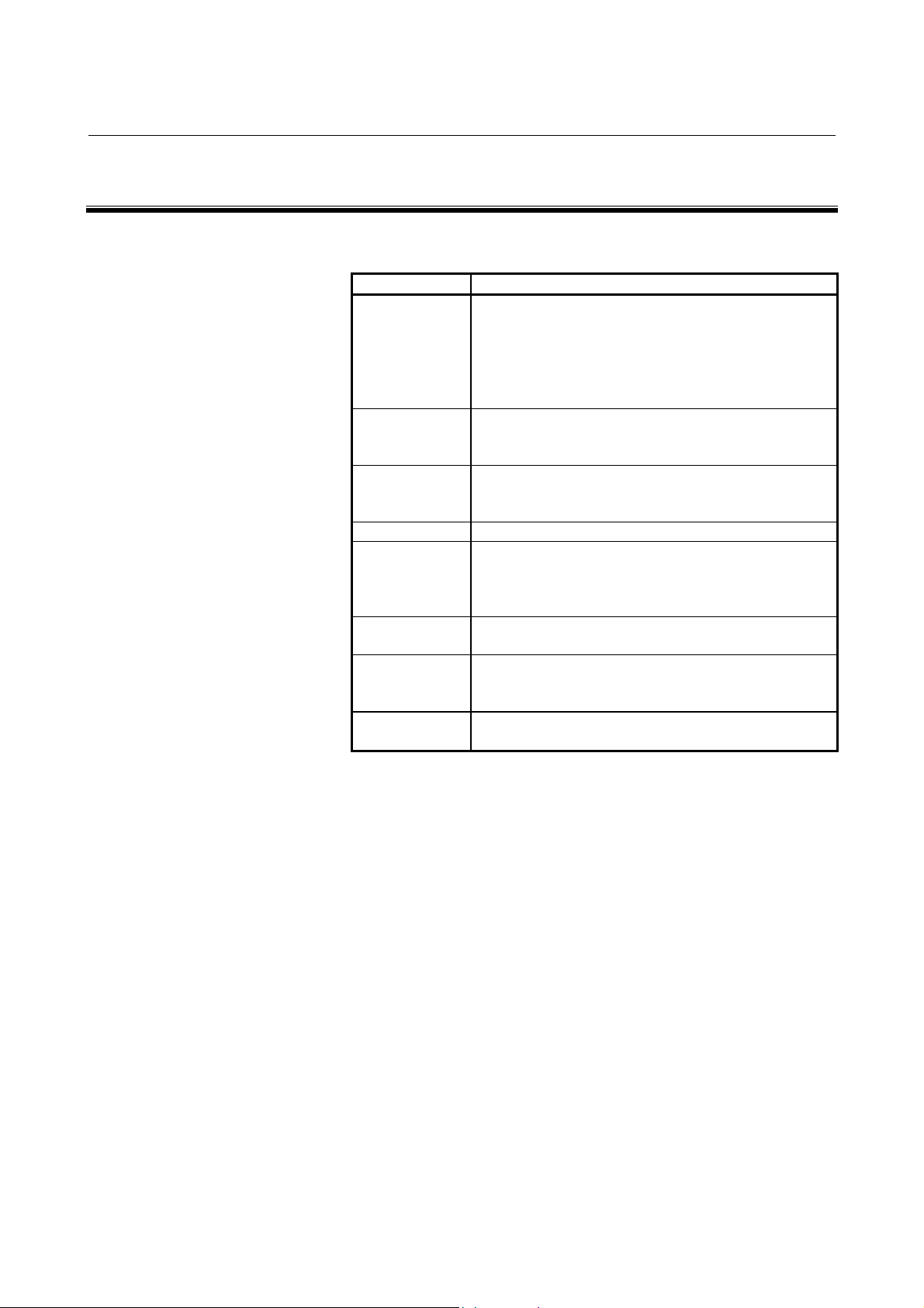
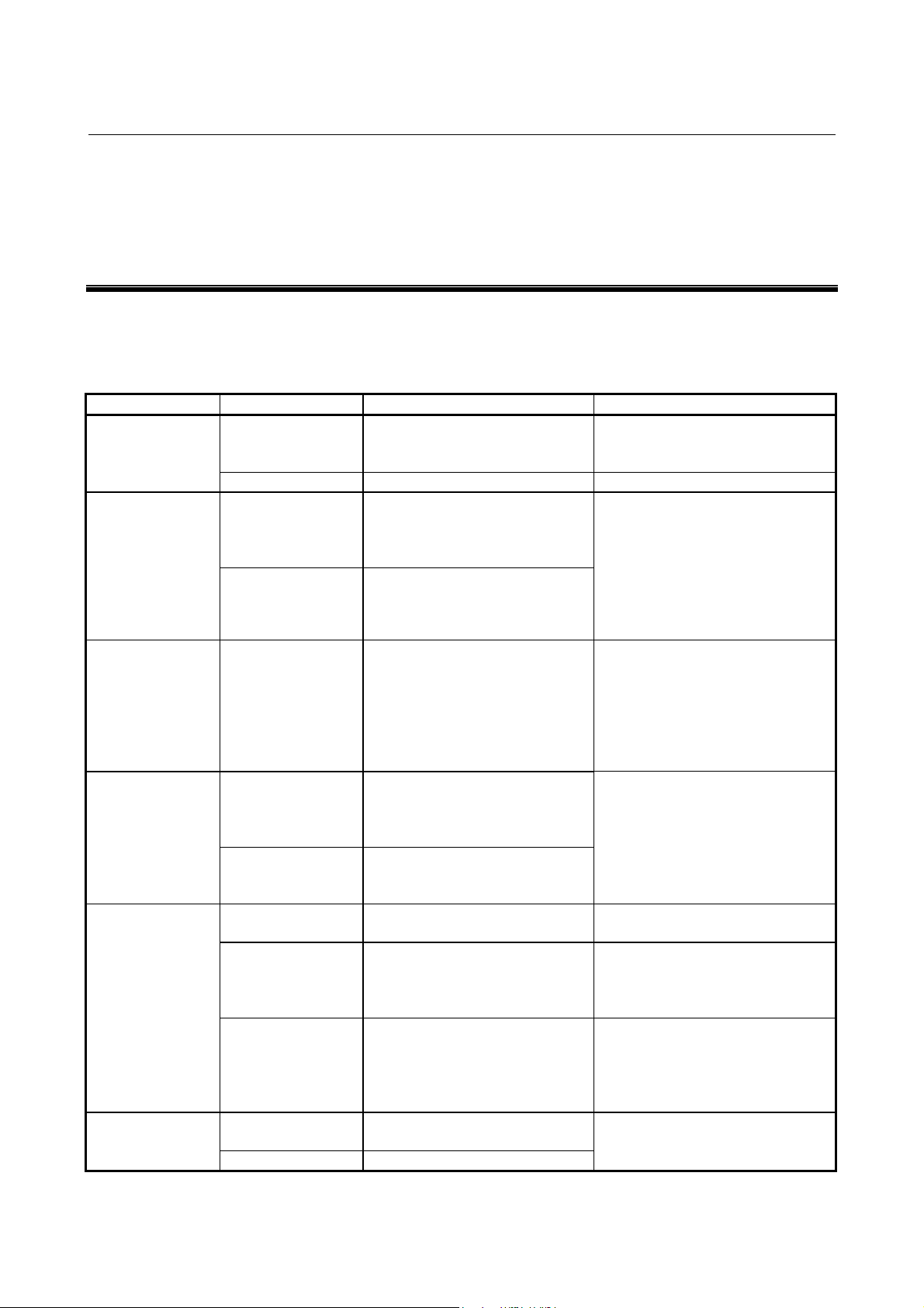
MOTOR INSULATION RESISTANCE MEASUREMENT
Measure an insulation resistance between each winding and
motor frame using an insulation resistance meter (500 VDC).
Judge the measurements according to the following table.
Insulation
resistance
100 MΩ or higher Acceptable
The winding has begun deteriorating. There is no
10 to 100 MΩ
1 to 10 MΩ
Lower than 1 MΩ Unacceptable. Replace the motor.
problem with the performance at present. Be
sure to perform periodic inspection.
The winding has considerably deteriorated.
Special care is in need. Be sure to perform
periodic inspection.
Judgment
s-8
Page 11
B-65272EN/04 PREFACE
PREFACE
The models covered by this manual, and their abbreviations are:
Series Model
α0.5/10000i, α1/10000i, α1.5/10000i, α2/10000i,
α3/10000i, α6/10000i, α8/8000i, α12/7000i, α15/7000i,
αi series
αiP series
αiT series
αiL series α8/20000iL, α15/15000iL, α26/15000iL
α(HV)i series
α(HV)iP
series
α(HV)iT
series
α(HV)iL
series
α18/7000i, α22/7000i, α30/6000i, α40/6000i, α50/4500i,
α1/15000i, α1.5/15000i, α2/15000i, α3/12000i, α6/12000i,
α8/10000i, α12/10000i, α15/10000i, α18/10000i,
α22/10000i
α12/6000i
α30/6000i
α12/8000i
α1.5/15000i
α8/12000i
α22/10000i
P, α15/6000iP, α18/6000iP, α22/6000iP,
P, α40/6000iP, α50/6000iP, α60/4500iP,
P, α15/8000iP, α18/8000iP, α22/8000iP
T, α2/15000iT, α3/12000iT, α6/12000iT,
T, α8/15000iT, α15/10000iT, α15/12000iT,
T
α0.5/10000HVi, α1/10000HVi, α1.5/10000HVi,
α2/10000HVi, α3/10000HVi, α6/10000HVi, α8/8000HVi,
α12/7000HVi, α15/7000HVi, α22/7000HVi, α30/6000HVi,
α40/6000HVi, α60/4500HVi, α100/4000HVi
α15/6000HViP, α22/6000HViP, α40/6000HViP,
α50/6000HVi
α1.5/15000HVi
α6/12000HVi
α15/10000HVi
α8/20000HVi
P, α60/4500HviP
T, α2/15000HViT, α3/12000HViT,
T, α8/12000HViT, α8/15000HViT,
T, α15/12000HViT, α22/10000HviT
L, α15/15000HViL, α26/15000HViL
p-1
Page 12

Page 13

B-65272EN/04 TABLE OF CONTENTS
TABLE OF CONTENTS
SAFETY PRECAUTIONS.......................................................................... s-1
I. DESCRIPTIONS FOR THE αi SERIES
1 GENERAL ..............................................................................................3
2 CONFIGURATION OF THE ααααi SERIES .................................................5
3 MOTOR TYPES .....................................................................................6
4 NOTES ON INSTALLATION ..................................................................7
4.1 COMMON ......................................................................................................8
4.2 POWER LEAD CONNECTION....................................................................19
4.3 FAN MOTOR CONNECTION ......................................................................24
4.4 WHEN A MOTOR IS CONNECTED TO A SPINDLE VIA A BELT ..............27
4.5 WHEN A MOTOR IS CONNECTED TO A SPINDLE VIA A GEAR.............30
4.6 WHEN A MOTOR IS DIRECTLY CONNECTED TO A SPINDLE VIA
A COUPLING...............................................................................................31
5 NOTES ON OPERATION.....................................................................32
6 DETERMINING THE ACCELERATION TIME ......................................33
7 DETERMINING THE ALLOWABLE DUTY CYCLE .............................39
8 DISPOSAL OF SPINDLE MOTORS BY MATERIAL TYPE .................42
II. FANUC AC SPINDLE MOTOR αi SERIES
1 GENERAL ............................................................................................45
2 SPECIFICATIONS................................................................................46
3 OUTPUT/TORQUE CHARACTERISTICS ............................................56
3.1 MODEL α0.5/10000i....................................................................................57
3.2 MODEL α1/10000i.......................................................................................57
3.3 MODEL α1.5/10000i....................................................................................58
3.4 MODEL α2/10000i.......................................................................................58
3.5 MODEL α3/10000i.......................................................................................59
3.6 MODEL α6/10000i.......................................................................................59
3.7 MODEL α8/8000i.........................................................................................60
3.8 MODEL α12/7000i.......................................................................................60
c-1
Page 14

TABLE OF CONTENTS B-65272EN/04
3.9 MODEL α15/7000i.......................................................................................61
3.10 MODEL α18/7000i.......................................................................................61
3.11 MODEL α22/7000i.......................................................................................62
3.12 MODEL α30/6000i.......................................................................................62
3.13 MODEL α40/6000i.......................................................................................63
3.14 MODEL α50/4500i.......................................................................................63
3.15 MODEL α1/15000i.......................................................................................64
3.16 MODEL α1.5/15000i....................................................................................65
3.17 MODEL α2/15000i.......................................................................................66
3.18 MODEL α3/12000i.......................................................................................67
3.19 MODEL α6/12000i.......................................................................................68
3.20 MODEL α8/10000i.......................................................................................69
3.21 MODEL α12/10000i.....................................................................................70
3.22 MODEL α15/10000i.....................................................................................71
3.23 MODEL α18/10000i.....................................................................................72
3.24 MODEL α22/10000i.....................................................................................73
4 CONNECTIONS ...................................................................................74
4.1 MODEL α0.5/10000i....................................................................................75
4.2 MODELS α1/10000i TO α50/4500i .............................................................77
4.3 CONNECTION OF SIGNAL LEAD ..............................................................78
5 ALLOWABLE RADIAL LOAD..............................................................79
6 ASSEMBLING ACCURACY.................................................................80
7 EXTERNAL DIMENSIONS...................................................................81
7.1 MODEL α0.5/10000i (FLANGE MOUNTING TYPE) ...................................82
7.2 MODELS α1/10000i AND α1/15000i (FLANGE MOUNTING TYPE) ..........83
7.3 MODEL α1/10000i (FOOT MOUNTING TYPE)...........................................84
7.4 MODEL α1.5/10000i (FLANGE MOUNTING TYPE) ...................................85
7.5 MODEL α1.5/15000i (FLANGE MOUNTING TYPE) ...................................86
7.6 MODEL α1.5/10000i (FOOT MOUNTING TYPE)........................................87
7.7 MODEL α2/10000i (FLANGE MOUNTING TYPE) ......................................88
7.8 MODEL α2/15000i (FLANGE MOUNTING TYPE) ......................................89
7.9 MODEL α2/10000i (FOOT MOUNTING TYPE)...........................................90
7.10 MODELS α3/10000i AND α3/12000i (FLANGE MOUNTING TYPE) ..........91
7.11 MODEL α3/10000i (FOOT MOUNTING TYPE)...........................................92
7.12 MODELS α6/10000i AND α6/12000i (FLANGE MOUNTING TYPE) ..........93
7.13 MODEL α6/10000i (FOOT MOUNTING TYPE)...........................................94
c-2
Page 15

B-65272EN/04 TABLE OF CONTENTS
7.14 MODELS α8/8000i AND α8/10000i (FLANGE MOUNTING TYPE) ............95
7.15 MODEL α8/8000i (FOOT MOUNTING TYPE).............................................96
7.16 MODELS α12/7000i AND α12/10000i (FLANGE MOUNTING TYPE) ........97
7.17 MODEL α12/7000i (FOOT MOUNTING TYPE)...........................................98
7.18 MODELS α15/7000i AND α15/10000i (FLANGE MOUNTING TYPE) ........99
7.19 MODEL α15/7000i (FOOT MOUNTING TYPE).........................................100
7.20 MODELS α18/7000i AND α18/10000i (FLANGE MOUNTING TYPE) ......101
7.21 MODEL α18/7000i (FOOT MOUNTING TYPE).........................................102
7.22 MODELS α22/7000i AND α22/10000i (FLANGE MOUNTING TYPE) ......103
7.23 MODEL α22/7000i (FOOT MOUNTING TYPE).........................................104
7.24 MODEL α30/6000i (FLANGE MOUNTING TYPE) ....................................105
7.25 MODEL α30/6000i (FOOT MOUNTING TYPE).........................................106
7.26 MODEL α40/6000i (FLANGE MOUNTING TYPE) ....................................107
7.27 MODEL α40/6000i (FOOT MOUNTING TYPE).........................................108
7.28 MODEL α50/4500i (FLANGE MOUNTING TYPE) ....................................109
7.29 MODEL α50/4500i (FOOT MOUNTING TYPE).........................................110
III. FANUC AC SPINDLE MOTOR αiP SERIES
1 GENERAL ..........................................................................................113
2 SPECIFICATIONS..............................................................................114
3 OUTPUT/TORQUE CHARACTERISTICS ..........................................120
3.1 MODEL α12/6000iP ...................................................................................121
3.2 MODEL α15/6000iP ...................................................................................122
3.3 MODEL α18/6000iP ...................................................................................123
3.4 MODEL α22/6000iP ...................................................................................124
3.5 MODEL α30/6000iP ...................................................................................125
3.6 MODEL α40/6000iP ...................................................................................126
3.7 MODEL α50/6000iP ...................................................................................127
3.8 MODEL α60/4500iP ...................................................................................128
3.9 MODEL α12/8000iP ...................................................................................129
3.10 MODEL α15/8000iP ...................................................................................130
3.11 MODEL α18/8000iP ...................................................................................131
3.12 MODEL α22/8000iP ...................................................................................132
4 CONNECTIONS .................................................................................133
4.1 MODELS α12/6000iP TO α60/4500iP ........................................................134
4.2 CONNECTION OF SIGNAL LEAD ............................................................135
c-3
Page 16

TABLE OF CONTENTS B-65272EN/04
5 ALLOWABLE RADIAL LOAD............................................................136
6 ASSEMBLING ACCURACY...............................................................137
7 EXTERNAL DIMENSIONS.................................................................138
7.1 MODELS α12/6000iP AND α12/8000iP (FRANGE MOUNTING TYPE).....139
7.2 MODEL α12/6000iP (FOOT MOUNTING TYPE) .......................................140
7.3 MODELS α15/6000i
7.4 MODEL α15/6000iP (FOOT MOUNTING TYPE) .......................................142
7.5 MODELS α18/6000i
7.6 MODEL α18/6000iP (FOOT MOUNTING TYPE) .......................................144
7.7 MODELS α22/6000iP AND α22/8000iP (FRANGE MOUNTING TYPE).....145
7.8 MODEL α22/6000iP (FOOT MOUNTING TYPE) .......................................146
7.9 MODELS α30/6000i
7.10 MODELS α30/6000iP AND α40/6000iP (FOOT MOUNTING TYPE) .........148
7.11 MODEL α50/6000iP (FRANGE MOUNTING TYPE) ..................................149
7.12 MODEL α50/6000iP (FOOT MOUNTING TYPE) .......................................150
7.13 MODEL α60/4500iP (FRANGE MOUNTING TYPE) ..................................151
7.14 MODEL α60/4500iP (FOOT MOUNTING TYPE) .......................................152
P AND α15/8000iP (FRANGE MOUNTING TYPE).....141
P AND α18/8000iP (FRANGE MOUNTING TYPE).....143
P AND α40/6000iP (FRANGE MOUNTING TYPE).....147
IV. FANUC AC SPINDLE MOTOR αiT SERIES
1 GENERAL ..........................................................................................155
2 SPECIFICATIONS..............................................................................157
3 OUTPUT/TORQUE CHARACTERISTICS ..........................................163
3.1 MODEL α1.5/15000iT ................................................................................164
3.2 MODEL α2/15000iT ...................................................................................165
3.3 MODEL α3/12000iT ...................................................................................166
3.4 MODEL α6/12000iT ...................................................................................167
3.5 MODEL α8/12000iT ...................................................................................168
3.6 MODEL α8/15000iT ...................................................................................169
3.7 MODEL α15/10000iT .................................................................................170
3.8 MODEL α15/12000iT .................................................................................171
3.9 MODEL α22/10000iT .................................................................................172
4 CONFIGURATION AND ORDERING NUMBER ................................173
4.1 CONFIGURATION.....................................................................................174
4.2 ORDERING NUMBER ...............................................................................175
5 CONNECTIONS .................................................................................176
c-4
Page 17

B-65272EN/04 TABLE OF CONTENTS
5.1 CONNECTION OF THE POWER, FAN MOTOR, AND MZi SENSOR
SIGNAL LEADS.........................................................................................177
5.2 CONNECTION OF SIGNAL LEAD ............................................................179
6 ASSEMBLING ACCURACY...............................................................180
7 EXTERNAL DIMENSIONS.................................................................181
7.1 MODEL α1.5/15000iT ................................................................................182
7.2 MODEL α2/15000iT ...................................................................................183
7.3 MODEL α3/12000i
7.4 MODEL α6/12000iT ...................................................................................185
7.5 MODELS α8/12000iT AND α8/15000iT......................................................186
7.6 MODEL α15/10000iT .................................................................................187
7.7 MODEL α15/12000i
7.8 MODEL α22/10000iT .................................................................................189
7.9 DISTANCE BLOCK TYPE 1.5iT................................................................190
7.10 DISTANCE BLOCK TYPE 2iT...................................................................191
7.11 DISTANCE BLOCK TYPE 6iT...................................................................192
7.12 DISTANCE BLOCK TYPE 15iT.................................................................193
T ...................................................................................184
T .................................................................................188
8 POINTS ABOUT DIRECT CONNECTION STRUCTURE...................194
9 NOTES ON MOTOR INSTALLATION................................................195
9.1 HIGHER-PRECISION MOUNTING FLANGE AND SHAFT .......................196
9.2 CENTERING USING CENTERING PLATES.............................................197
9.3 CHECKING MOTOR VIBRATION (TO SEE WHETHER CENTERING
IS SUCCESSFUL) .....................................................................................198
9.4 COUPLING SELECTION...........................................................................199
9.5 ROTATION JOINT .....................................................................................202
9.6 COOLANT JOINT ......................................................................................203
9.7 ROTATION JOINT SUPPORT HOUSING .................................................205
V. FANUC AC SPINDLE MOTOR αiL SERIES
1 GENERAL ..........................................................................................209
2 SPECIFICATIONS..............................................................................210
3 OUTPUT/TORQUE CHARACTERISTICS ..........................................213
3.1 MODEL α8/20000iL....................................................................................214
3.2 MODEL α15/15000iL..................................................................................215
3.3 MODEL α26/15000iL..................................................................................216
c-5
Page 18

TABLE OF CONTENTS B-65272EN/04
4 CONNECTIONS .................................................................................217
4.1 TOTAL CONNECTION DIAGRAM ............................................................218
4.2 SIZE OF POWER LEAD ............................................................................219
4.3 CONNECTION OF SIGNAL LEAD ............................................................220
4.4 COOLING ..................................................................................................221
5 ASSEMBLING ACCURACY...............................................................223
6 EXTERNAL DIMENSIONS.................................................................224
6.1 MODEL α8/20000iL....................................................................................225
6.2 MODEL α15/15000iL..................................................................................226
6.3 MODEL α26/15000iL..................................................................................227
VI. FANUC AC SPINDLE MOTOR α(HV)i SERIES
1 GENERAL ..........................................................................................231
2 SPECIFICATIONS..............................................................................232
3 OUTPUT/TORQUE CHARACTERISTICS ..........................................238
3.1 MODEL α0.5/10000HVi.............................................................................239
3.2 MODEL α1/10000HVi................................................................................239
3.3 MODEL α1.5/10000HVi.............................................................................240
3.4 MODEL α2/10000HVi................................................................................240
3.5 MODEL α3/10000HVi................................................................................241
3.6 MODEL α6/10000HVi................................................................................241
3.7 MODEL α8/8000HVi..................................................................................242
3.8 MODEL α12/7000HVi................................................................................242
3.9 MODEL α15/7000HVi................................................................................243
3.10 MODEL α22/7000HVi................................................................................243
3.11 MODEL α30/6000HVi................................................................................244
3.12 MODEL α40/6000HVi................................................................................244
3.13 MODEL α60/4500HVi................................................................................245
3.14 MODEL α100/4000HVi..............................................................................246
4 CONNECTIONS .................................................................................247
4.1 MODEL α0.5/10000HVi.............................................................................248
4.2 MODELS α1/10000HVi TO α100/4000HVi ...............................................250
4.3 CONNECTION OF SIGNAL LEAD ............................................................251
5 ALLOWABLE RADIAL LOAD............................................................252
6 ASSEMBLING ACCURACY...............................................................253
c-6
Page 19

B-65272EN/04 TABLE OF CONTENTS
7 EXTERNAL DIMENSIONS.................................................................254
7.1 MODEL α0.5/10000HVi (FLANGE MOUNTING TYPE) ............................255
7.2 MODEL α1/10000HVi (FLANGE MOUNTING TYPE) ...............................256
7.3 MODEL α1/10000HVi (FOOT MOUNTING TYPE)....................................257
7.4 MODEL α1.5/10000HVi (FLANGE MOUNTING TYPE) ............................258
7.5 MODEL α1.5/10000HVi (FOOT MOUNTING TYPE).................................259
7.6 MODEL α2/10000HVi (FLANGE MOUNTING TYPE) ...............................260
7.7 MODEL α2/10000HVi (FOOT MOUNTING TYPE)....................................261
7.8 MODEL α3/10000HVi (FLANGE MOUNTING TYPE) ...............................262
7.9 MODEL α3/10000HVi (FOOT MOUNTING TYPE)....................................263
7.10 MODEL α6/10000HVi (FLANGE MOUNTING TYPE) ...............................264
7.11 MODEL α6/10000HVi (FOOT MOUNTING TYPE)....................................265
7.12 MODEL α8/8000HVi (FLANGE MOUNTING TYPE) .................................266
7.13 MODEL α8/8000HVi (FOOT MOUNTING TYPE)......................................267
7.14 MODEL α12/7000HVi (FLANGE MOUNTING TYPE) ...............................268
7.15 MODEL α12/7000HVi (FOOT MOUNTING TYPE)....................................269
7.16 MODEL α15/7000HVi (FLANGE MOUNTING TYPE) ...............................270
7.17 MODEL α15/7000HVi (FOOT MOUNTING TYPE)....................................271
7.18 MODEL α22/7000HVi (FLANGE MOUNTING TYPE) ...............................272
7.19 MODEL α22/7000HVi (FOOT MOUNTING TYPE)....................................273
7.20 MODEL α30/6000HVi (FLANGE MOUNTING TYPE) ...............................274
7.21 MODEL α30/6000HVi (FOOT MOUNTING TYPE)....................................275
7.22 MODEL α40/6000HVi (FLANGE MOUNTING TYPE) ...............................276
7.23 MODEL α40/6000HVi (FOOT MOUNTING TYPE)....................................277
7.24 MODEL α60/4500HVi (FLANGE MOUNTING TYPE) ...............................278
7.25 MODEL α60/4500HVi (FOOT MOUNTING TYPE)....................................279
7.26 MODEL α100/4000HVi (FOOT FLANGE MOUNTING TYPE) ..................280
VII. FANUC AC SPINDLE MOTOR α(HV)iP SERIES
1 GENERAL ..........................................................................................283
2 SPECIFICATIONS..............................................................................284
3 OUTPUT/TORQUE CHARACTERISTICS ..........................................289
3.1 MODEL α15/6000HViP ..............................................................................290
3.2 MODEL α22/6000HViP ..............................................................................291
3.3 MODEL α40/6000HViP ..............................................................................292
3.4 MODEL α50/6000HViP ..............................................................................293
c-7
Page 20

TABLE OF CONTENTS B-65272EN/04
3.5 MODEL α60/4500HViP ..............................................................................294
4 CONNECTIONS .................................................................................295
4.1 MODELS α15/6000HViP TO α60/4500HViP ..............................................296
4.2 CONNECTION OF SIGNAL LEAD ............................................................297
5 ALLOWABLE RADIAL LOAD............................................................298
6 ASSEMBLING ACCURACY...............................................................299
7 EXTERNAL DIMENSIONS.................................................................300
7.1 MODEL α15/6000HViP (FLANGE MOUNTING TYPE)..............................301
7.2 MODEL α15/6000HViP (FOOT MOUNTING TYPE) ..................................302
7.3 MODEL α22/6000HViP (FLANGE MOUNTING TYPE)..............................303
7.4 MODEL α22/6000HViP (FOOT MOUNTING TYPE) ..................................304
7.5 MODEL α40/6000HVi
7.6 MODEL α40/6000HViP (FOOT MOUNTING TYPE) ..................................306
7.7 MODEL α50/6000HViP (FLANGE MOUNTING TYPE)..............................307
7.8 MODEL α50/6000HViP (FOOT MOUNTING TYPE) ..................................308
7.9 MODEL α60/4500HViP (FLANGE MOUNTING TYPE)..............................309
7.10 MODEL α60/4500HViP (FOOT MOUNTING TYPE) ..................................310
P (FLANGE MOUNTING TYPE)..............................305
VIII. FANUC AC SPINDLE MOTOR α(HV)iT SERIES
1 GENERAL ..........................................................................................313
2 SPECIFICATIONS..............................................................................314
3 OUTPUT/TORQUE CHARACTERISTICS ..........................................320
3.1 MODEL α1.5/15000HViT ...........................................................................321
3.2 MODEL α2/15000HViT ..............................................................................322
3.3 MODEL α3/12000HViT ..............................................................................323
3.4 MODEL α6/12000HViT ..............................................................................324
3.5 MODEL α8/12000HViT ..............................................................................325
3.6 MODEL α8/15000HViT ..............................................................................326
3.7 MODEL α15/10000HViT ............................................................................327
3.8 MODEL α15/12000HViT ............................................................................328
3.9 MODEL α22/10000HViT ............................................................................329
4 CONFIGURATION AND ORDERING NUMBER ................................330
4.1 CONFIGURATION.....................................................................................331
4.2 ORDERING NUMBER ...............................................................................332
c-8
Page 21

B-65272EN/04 TABLE OF CONTENTS
5 CONNECTIONS .................................................................................333
5.1 CONNECTION OF THE POWER, FAN MOTOR, AND MZi SENSOR
SIGNAL LEADS.........................................................................................334
5.2 CONNECTION OF A SINGLE-PHASE FAN MOTOR ...............................335
5.3 CONNECTION OF SIGNAL LEAD ............................................................336
6 ASSEMBLING ACCURACY...............................................................337
7 EXTERNAL DIMENSIONS.................................................................338
7.1 MODEL α1.5/15000HViT ...........................................................................339
7.2 MODEL α2/15000HViT ..............................................................................340
7.3 MODEL α3/12000HViT ..............................................................................341
7.4 MODEL α6/12000HViT ..............................................................................342
7.5 MODELS α8/12000HVi
7.6 MODEL α15/10000HViT ............................................................................344
7.7 MODEL α15/12000HViT ............................................................................345
7.8 MODEL α22/10000HViT ............................................................................346
T AND α8/15000HViT ............................................343
IX. FANUC AC SPINDLE MOTOR α(HV)iL SERIES
1 GENERAL ..........................................................................................349
2 SPECIFICATIONS..............................................................................350
3 OUTPUT/TORQUE CHARACTERISTICS ..........................................353
3.1 MODEL α8/20000HViL...............................................................................354
3.2 MODEL α15/15000HViL.............................................................................355
3.3 MODEL α26/15000HViL.............................................................................356
4 CONNECTIONS .................................................................................357
4.1 POWER WIRE CRIMP TERMINAL SIZE ..................................................358
4.2 CONNECTION OF SIGNAL LEAD ............................................................359
4.3 COOLING ..................................................................................................360
5 ASSEMBLING ACCURACY...............................................................362
6 EXTERNAL DIMENSIONS.................................................................363
6.1 MODEL α8/20000HViL...............................................................................364
6.2 MODEL α15/15000HViL.............................................................................365
6.3 MODEL α26/15000HViL.............................................................................366
c-9
Page 22

Page 23

I. DESCRIPTIONS FOR THE ααααi SERIES
Page 24

Page 25

B-65272EN/04 SPECIFICATIONS FOR THE αi SERIES 1.GENERAL
α
α
1 GENERAL
As motors for driving the spindle of a CNC machine tool, the FANUC
AC Spindle Motor αi series has incorporated accumulated
technologies and employs the latest design and manufacturing
techniques to provide the features listed below.
Features
- The series provides a lineup of motors that satisfy various
spindle driving structures such as gear driving, belt driving, and
direct motor connection. So, the user can choose an optimal
motor that meets the spindle driving structure of the user.
- By employing winding switching, a wider rated output range
required for the spindle driving motor of a machine tool is
achieved. With the αi series, a high-speed winding is used to
remarkably increase the output level in the high-speed area, thus
reducing acceleration/deceleration time. With the αi
low-speed winding is used to increase the torque by a factor of
1.5.
- An up-to-date stator cooling method is employed for direct aircooling of the electromagnetic steel plate. So, a high power and
high torque are achieved with a compact size.
- By precision rotor aluminum casting and accurate rotor balance
correction, vibration grade V3 (option) is achieved even at high
speed.
- The user can select a motor fan exhaust direction: forward
direction or backward direction. An exhaust direction that
subjects the machine to less heat deformation can be selected.
With the αi series, the cooling air path is optimized to further
improve cooling performance.
- Two types of speed sensors built into the motor are available: Mi
sensor based on the A/B-phase signal and MZi sensor based on
the A/B-phase signal and one-rotation signal. The user can
choose between the two types according to the spindle
configuration and spindle function.
- This series employ waterproof and pressure-proof design
conforming to the international standard (IEC).
P series, a
i series
- 3 -
iT series
Page 26
1.GENERAL SPECIFICATIONS FOR THE αi SERIES B-65272EN/04
α
α
α
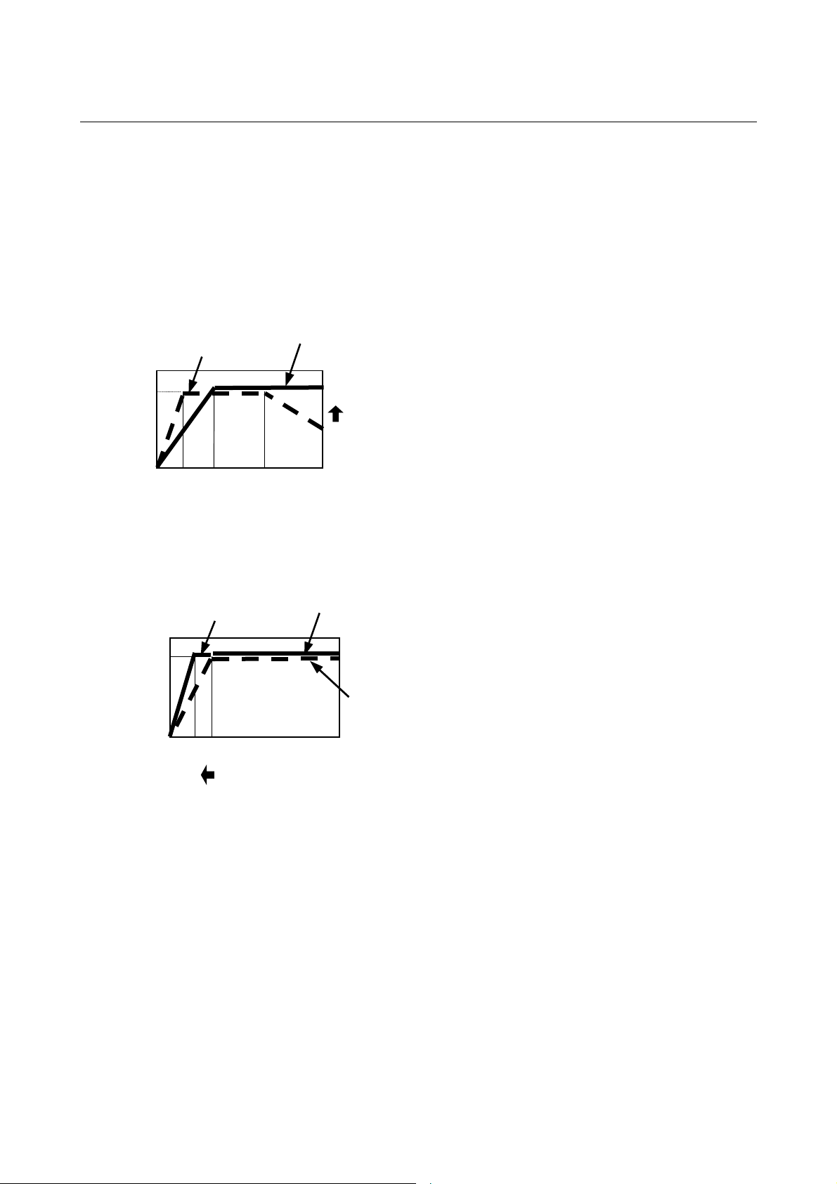
Features of ααααi
- Higher speed
- Increased rated output range by employing winding switching
i, αiT : Remarkable output increase in the high-speed area by employing a high-speed winding.
→ Enables highly efficient cutting and acceleration time reduction
α6/12000i
α6/12000i
(High-speed winding)
(Low-speed winding)
(kW)
7.5
0
4000
1500
Motor speed (min-1)
8000
7.5kW
Output : 2 times
3.7kW
12000
iP: Remarkable torque increase in the low-speed area by employing a low-speed winding
→ Enables optimal spindle speed selection and motor model downsizing
α12/6000iP
(Low-speed winding)
(kW)
7.5
α12/6000iP
(High-speed winding)
P12/6000
0
Torque : 1.5 times
750
500
Motor speed (min-1)
6000
- Low vibration: Vibration grade V3 (optional specification with the non-key type
only)
- 4 -
Page 27
B-65272EN/04 SPECIFICATIONS FOR THE αi SERIES 2.CONFIGURATION OF THE αi series
2 CONFIGURATION OF THE α
αi series
αα
The FANUC AC Spindle Motor αi series consists of the series listed
below with their features.
Feature
Series
αi
αiP
α(HV)i
αiT
αiL
Rated
output
0.55 to 45 Standard motors for machine-tool spindles
5.5 to 30
0.55 to 100
Motors with constant output over a wide range, which require no
reduction units
αi series directly connectable to a 400 V power supply
1.5 to 22 Model for direct spindle connection used with machining centers
7.5 to 30
Liquid-cooled model for direct spindle connection used with high
precision machining centers
Feature
Lineup for ααααi series spindle motor
Continuous
rated output
0.55
1.1
1.5
2.2
3.7
5.5
7.5
9
11
15
18.5
22
30
37
45
60
100
15000 Highest-speed upgraded model Model supporting winding switching
ααααi ααααi
αααα0.5/
10000i
αααα1/
10000i
αααα1.5/
10000i
αααα2/
10000i
αααα3/
10000i
αααα6/
10000i
αααα8/
8000i
αααα12/
7000i
αααα15/
7000i
αααα18/
7000i
αααα22/
7000i
αααα30/
6000i
α40/
6000i
α50/
4500i
α1/
15000i
α1.5/
15000i
α2/
15000i
α3/
12000i
α6/
12000i
αααα8/
10000i
αααα12/
10000i
αααα15/
10000i
αααα18/
10000i
αααα22/
10000i
P α
α12/
6000iP
α15/
6000iP
α18/
6000iP
α22/
6000iP
αααα30/
6000iP
αααα40/
6000iP
αααα50/
6000iP
α60/
4500iP
αiT ααααiL αααα(HV)i αααα(HV)iP αααα(HV)iT αααα(HV)iL
αα
αααα0.5/
10000HVi
αααα1/
10000HVi
α1.5/
15000i
α2/
15000i
α3/
12000i
α6/
12000iT
α8/
12000iT
α15/
12000iT
α22/
10000iT
T
T
T
α8/
20000iL
α15/
15000iL
α26/
15000iL
αααα1.5/
10000HVi
αααα2/
10000HVi
αααα3/
10000HVi
αααα6/
10000HVi
αααα8/
8000HVi
αααα12/
7000HVi
αααα15/
7000HVi
αααα22/
7000HVi
αααα30/
6000HVi
α40/
6000HVi
α60/
4500HVi
αααα100/
4000HVi
α15/
6000HViP
α22/
6000HViP
α40/
6000HViP
α50/
6000HViP
α60/
4500HViP
Example of
applicable
machine
For Lathe and
Machining center
For Machining
center
α1.5/
15000HVi
15000HVi
12000HVi
12000HViT
12000HViT
12000HViT
10000HViT
T
α2/
T
α3/
T
α6/
α8/
α15/
α22/
α8/
20000HViL
α15/
15000HViL
α26/
15000HViL
- 5 -
Page 28
3.MOTOR TYPES SPECIFICATIONS FOR THE αi SERIES B-65272EN/04
3 MOTOR TYPES
Each model includes the types of motors listed below, and the user
can make an optimal choice according to the spindle driving structure.
See the ordering list (B-65271EN) for available motors.
Item Type Use Remarks
Mounting types
Built-in sensor
Connected to spindle via a gear
Flange mounting type
Foot mounting type Connected to spindle via a belt
Mi sensor
MZi sensor
Directly connected to a spindle
Connected to spindle via a belt
When connected to the spindle via a
belt or gear at a deceleration ratio
other than 1:1
(When the spindle has a sensor)
When connected to the spindle via a
belt, gear, or coupling on a 1:1 basis
(When the spindle has no sensor)
The motor can be positioned
accurately.
For a detailed explanation, refer to the
following descriptions:
Subsection, “Spindle Amplifier Module
(SPM)” in the SERVO AMPLIFIER αi
series DESCRIPTIONS (B-65282EN)
Shaft figure With no key Connected to a pulley
Rearward exhaust
Cooling air exhaust
direction
Output shaft seal
Maximum speed
(Exhaust from side
opposite the output
shaft)
Forward exhaust
(Exhaust from the
output shaft side)
Oil seal
Labyrinth
No seal
Standard-speed
model
High-speed model -
When the machine is positioned at
the output shaft side
When the machine is positioned at
the side opposite the output shaft
Gear connection, direct connection,
and belt driving
Belt driving and direct connection
(Only when no lubricant or coolant
splashes onto the flange surface of
the motor)
Belt driving
(Only when no lubricant splashes
onto the flange surface of the motor)
-
A shaft with no key is used as
standard to facilitate pulley and gear
balance correction and acceleration/
deceleration operation.
When a shaft with a key is needed,
contact your FANUC sales
representative.
Direct the exhaust out and away from
the machine.
Used in flange mounting type
standard-speed models.
Used in flange mounting type highspeed models. (Some high-speed
models have an oil seal.)
Foot-mounting type models have no
output shaft seal, but can be changed
to a model with an oil seal or labyrinth.
For the models that can be changed,
refer to "Order List" (B-65271EN).
Consider the maximum speed of each
model and select a model accordingly.
- 6 -
Page 29

B-65272EN/04 SPECIFICATIONS FOR THE αi SERIES 4.NOTES ON INSTALLATION
4 NOTES ON INSTALLATION
- 7 -
Page 30
4.NOTES ON INSTALLATION SPECIFICATIONS FOR THE αi SERIES B-65272EN/04
4.1 COMMON
Be sure to observe the following, regardless of the connection method
of the motor:
WARNING
When connecting a metallic conduit to a plastic terminal box, connect
the conduit to ground on the power magnetics cabinet side.
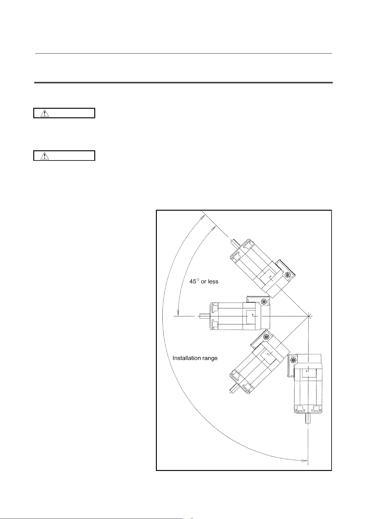
CAUTION
1 Mount the motor so that the output shaft points in a direction
ranging within 45° degrees above the horizontal to vertically
downwards.
2 When the motor needs to be pointed to more than 45° degrees
above the horizontal, consult you FANUC representative.
- 8 -
Page 31

B-65272EN/04 SPECIFICATIONS FOR THE αi SERIES 4.NOTES ON INSTALLATION
3 Use the eyebolt of the motor to lift only a single motor, (gear and
pulley may be attached).
4 Place a cover over an air-cooled motor to prevent the motor from
being exposed to coolant or lubricant.
5 Limit the vibration acceleration at the rear bracket of the motor
to 0.5 G (4.9 m/s
2
) to ensure the long-term reliability of each part
of the motor.
In particular, to limit the acceleration in the case of direct
connection to 0.5 G, carefully perform centering with the mating
spindle and make the motor shaft parallel with the spindle.
Details of the measuring method
Measuring instrument:
Equivalent to the VM-3314A or VM-3304 manufactured by
IMV CORPORATION.
Condition: At the time of highest-speed rotation with no load
Measurement frequency range with no load at the highest speed:
10 to 1000 Hz
Criteria: 0.5 G (4.9 m/s
1. Using a pickup
A. Pressing a pickup against
the side of the rear bracket
2
) or less at the rear bracket
B. Screwing a block into the eyebolt
internal thread on the rear
bracket, then screwing a pickup
into the block.
Block
Pickup
Side of the rear bracket
2. Vibration measurement position (rear bracket)
Eyebolt
internal thread
- 9 -
Pickup
Eyebolt internal thread
Side of the rear bracket
Page 32

4.NOTES ON INSTALLATION SPECIFICATIONS FOR THE αi SERIES B-65272EN/04
6 Dynamic balance
During high-speed operation, a small imbalance may cause a
large vibration, resulting in an unusual sound, premature bearing
damage, or some other abnormality.
Therefore, reduce the amount of the imbalance with the dynamic
balance of the other rotation shafts, as well as the gear and
pulley mounted on the output shaft of the motor, as much as
possible.
- Balance correction
With the αi series, a shaft with no key is used as standard to
facilitate the balance correction of a pulley, gear, and
coupling attached to the shaft. Use a completely symmetric
pulley, gear, or coupling, and use a backlash-less tightening
part such as a SPANN ELEMENTE to secure a pulley, gear,
or coupling to the shaft. When attaching a pulley to a shaft,
for example, adjust the periphery vibration to within 20 µm.
This basically eliminates the need for balance correction.
To further reduce the vibration level, make a field balance
correction, for example, by tightening a screw into the
tapped hole for balance correction provided on a
component such as a pulley.
NOTE
When a shaft with a key is required, contact your
FANUC sales representative.
- 10 -
Page 33

B-65272EN/04 SPECIFICATIONS FOR THE αi SERIES 4.NOTES ON INSTALLATION
7 Output shaft seal
To prevent cutting lubricant or dust from penetrating inside the
motor, one of the following output shaft seals is provided on the
output shaft. (For the use and applicable motors, see Chapter 3,
"MOTOR TYPES.")
For those models with an oil seal, ensure that the surface of the
lubricant is below the lip of the oil seal.
If a simple labyrinth is used as the output shaft seal (high-speed
model) or if no seal is provided (foot mounting type), ensure that
lubricant does not splash onto the flange surface. (If such a
motor is directly mounted on a gear box, the lubricant may
gradually penetrate inside the motor even when no lubricant
splashes on flange surface, thus resulting in motor failure.
Therefore, do not mount such a motor on a gear box directly.
- 11 -
Page 34

4.NOTES ON INSTALLATION SPECIFICATIONS FOR THE αi SERIES B-65272EN/04
8 The lid of the terminal box is provided with rubber gasket to
make it waterproof.
Check that the lid has this gasket, then mount it on the terminal
box.
9 The edge of the fauset joint to mount the flange mounting type
motor should be chamfered about C1.
10 Please space 30 mm or more between the fan cover and the
partition to keep the cooling ability well.
We recommend to take a structure such as you can clean air
holes and the fan cover easily.
- 12 -
Page 35

B-65272EN/04 SPECIFICATIONS FOR THE αi SERIES 4.NOTES ON INSTALLATION
11 If much oil mist, dust, or other foreign matter settles on the
motor, the cooling performance is degraded, resulting in
degraded performance of the motor. Design the machine such
that only clean cooling air is drawn into the motor.
Example)
When a duct with a filter is installed on a flange mounting
type motor with a rear exhaust (The filter requires periodic
cleaning.)
- 13 -
Page 36

4.NOTES ON INSTALLATION SPECIFICATIONS FOR THE αi SERIES B-65272EN/04
NOTE
1 A foot mounting type motor has no oil seal. When an oil seal is
required, add #0002 to the drawing number of the motor. An oil
seal cannot be attached to any high-speed model, however. For
details, refer to "Order List" (B-65271EN).
Example)
Model α12/7000i (foot mounting type, with no key,
rearward exhaust)
A06B-1408-B200
A06B-1408-B200#0002 (with oil seal)
2 When the oil seal is not exposed to lubricant, remove the coil
spring of the oil seal to decrease the friction between the lip and
shaft.
There is no problem with dry dust sealing.
If the motor is turned at high speed with the contact section
between the oil seal and shaft being dry, the contact section can
make an abnormal sound (interfering sound), or the lip can be
damaged.
- 14 -
Page 37

B-65272EN/04 SPECIFICATIONS FOR THE αi SERIES 4.NOTES ON INSTALLATION
3 Cable wiring
Follow the procedure below to install the cable.
(1) Use a hammer to strike the portion for the cable hole on the
terminal box and open the hole.
This time, pay attention not to break the other place except
hole. (In some models, it is not necessary to make a hole.)
(2) Thread the cable through a conduit. Connect the conduit
with the connector. (*1)
(3) Tighten the connector at the cable hole of the terminal box
using a nut. (*2, *3)
(4) Connect each terminal appropriately in the terminal box
with screws.
When a hole once made is not used, purchase the following
rubber bushing and mount it at the hole.
Do not open a hole where it is not required.
Break the thin plastic plate to make a hole.
Model Ordering number
α1i to α15i , α12iP to α22iP
α1.5/15000iT to α15/10000iT
α6HVi to α22HVi
α15HVi
α1.5/15000HViT to α22/10000HViT
α8/20000iL , α8/20000HViL
α18i, α22i, α30iP, α40iP, α50iP
α40HViP , α50HViP
α15/12000iT, α22/10000iT
α15/15000iL, α26/15000iL
α15/15000HViL, α26/15000HViL
P , α22HViP
A06B-0754-K001
A06B-0731-K001
High-speed models are same as above.
- 15 -
Page 38

4.NOTES ON INSTALLATION SPECIFICATIONS FOR THE αi SERIES B-65272EN/04
*1 If a 90° connector is used on any of the following models,
the mounting orientation of its conduit is limited as shown
below to avoid interference between the conduit and motor.
If you want to mount the conduit in any orientation, use a
45° connector. (For any model other than listed below, the
conduit for a 90° connector can be mounted in any
orientation.)
Applicable models :
α12i to α15i, α12i
α12HVi to α22HVi, α15/6000HVi
α15/10000HVi
Conduit mounting orientation for a 90° connector
Conduit mounting orientation for a 45° connector
P to α22iP, α15/10000iT,
P to α22/6000HViP,
T, α15/12000HViT, α22/10000HViT
*2 The nut used to fasten the connector to the terminal box
must be smaller than the size listed below. (Any larger nut
interferes with the terminal box.) For the diameter of the
cable hole in each model, refer to the outside dimension
drawing of the respective models.
Cable hole
diameter
φ42.5 mm 53 mm (maximum) 9 mm (maximum)
φ61 mm 80 mm (maximum) 15 mm (maximum)
Outside dimensions of the conduit-connector retaining nut
Outside diameter e Width t
e
t
- 16 -
Page 39

B-65272EN/04 SPECIFICATIONS FOR THE αi SERIES 4.NOTES ON INSTALLATION
*3 If the connector you want to use is smaller than the cable
hole on the terminal box, prepare the bushing, nut, and O-
ring shown below.
O-ring
Connector
Bushing
diameter
φφφφD
φ42.5 mm P46 C0462G
φ61 mm P65 C0650G
Nut
O-ring codeCable hole
JIS B 2401 ISO 3601-1
* For the diameter of the cable hole in each model, refer
to the outside dimension drawing of the respective
models.
- 17 -
Page 40

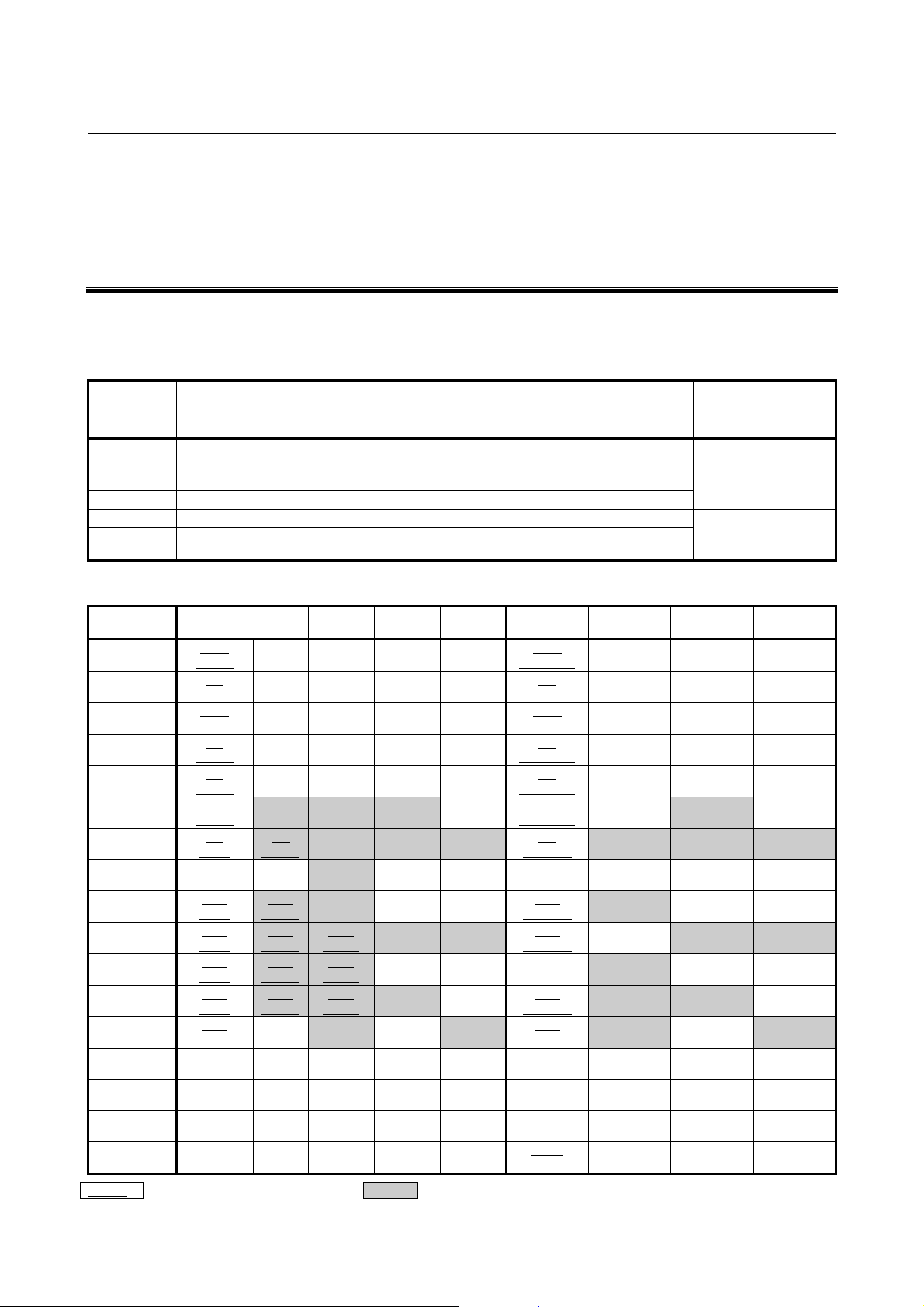
4.NOTES ON INSTALLATION SPECIFICATIONS FOR THE αi SERIES B-65272EN/04
4 Center of gravity
The distance L from the flange end face to the center of gravity
in each model is listed below.
Center
of gravity
L
ααααi
series
α0.5/10000i
α1/10000i
α1/15000i
α1.5/10000i
α1.5/15000i
α2/10000i
α2/15000i
α3/10000i
α3/12000i
α6/10000i
α6/12000i
α8/8000i
α8/10000i
α12/7000i
α12/10000i
α15/7000i
α15/10000i
α18/7000i
α18/10000i
α22/7000i
α22/10000i
α30/6000i α30/6000iP α30/6000HVi
α40/6000i α40/6000iP α40/6000HVi α40/6000HViP
-
α50/4500i
-
--
ααααiP
series
-
-
-
-
-
-
-
α12/6000iP
α12/8000iP
α15/6000iP
α15/8000iP
α18/6000iP
α18/6000iP
α22/6000iP
α22/8000iP
α50/4500i
α60/4500i
P
---
P α60/4500HVi α60/4500HViP
αααα (HV)i
series
α0.5/10000HVi
α1/10000HVi
α1.5/10000HVi
α2/10000HVi
α3/10000HVi
α6/10000HVi
α8/8000HVi
α12/7000HVi
α15/7000HVi α15/6000HViP
--
α22/7000HVi α22/6000HViP
-
α100/4000HVi
αααα(HV)iP
series
- 95±5
- 125±5
- 145±5
- 125±5
- 170±5
- 150±5
- 185±5
- 160±5
-
α50/6000HVi
-
Center of gravity [mm]
P
- 18 -
Page 41

B-65272EN/04 SPECIFICATIONS FOR THE αi SERIES 4.NOTES ON INSTALLATION
4.2 POWER LEAD CONNECTION
WARNING
To attach the power leads and jumpers, follow the procedure
described in this section to make connections with specified torque.
Driving a motor with terminals loosened could result in the terminal
board overheating and causing a fire. In addition, it may remove
terminal to cause a ground fault, short circuit, or electric shock.
CAUTION
1. When attaching the power leads and jumpers to the terminal
board of a motor, tighten the screws with torque specified in the
table. For the terminal size of a terminal board, refer to Chapter
4, "CONNECTIONS" in the manual of the corresponding series.
Terminal size
M4 1.1 to 1.5
M5 2.0 to 2.5
M6 3.5 to 4.5
M8 8 to 10
M10 15 to 16
Tightening torque
[N⋅⋅⋅⋅m]
2. To maintain the required isolation distance, observe the
following:
• When attaching a crimp terminal at the end of a power lead,
cover the crimped portion of the crimp terminal with
insulating tube.
• If the terminal board is provided with an insulating cover,
fasten the power leads with the screws, and then put back
the insulating cover in place.
3. If you want to energize an output switching type motor only with
the low- or high-speed winding rather than switching its output,
jumper the low- or high-speed winding, whichever is applicable,
and then connect three power leads (the U-, V-, and W-phase
wires) to the motor (except for the α15/12000i
T and αiL series
motors).
The output switching type motors in the αi series, αi
α(HV)i
P series come standard with jumpers in the terminal box.
P series, and
If you want to any other output switching type motor, place an
order for jumpers according to the following list.
- 19 -
Page 42

4.NOTES ON INSTALLATION SPECIFICATIONS FOR THE αi SERIES B-65272EN/04
Terminal
size
M5 Low-speed winding A65L-0001-0630/SS 1
M5 High-speed winding A65L-0001-0630/SD 3
M6 Low-speed winding A290-1410-X416 1
M6 High-speed winding A290-1410-X417 3
Specification of the
winding to be used
Ordering number
Required
quantity
- 20 -
Page 43

B-65272EN/04 SPECIFICATIONS FOR THE αi SERIES 4.NOTES ON INSTALLATION
X
X
4. How to connect power leads to output switching type motors
For output switching type motors, six power leads (the U-, V-,
W-, X-, Y-, and Z-phase wires) can be connected on the terminal
board.
•••• Detailed descriptions of an
M5 type terminal board
The terminal board has two
rows. The U-, V-, and W-phase
leads can be connected to the
upper row, while the Z-, X-, and
Y-phase wires can be
connected to the lower row.
1) Using the motor by switching its output
To use the motor by switching its output, connect the six
power leads (the U-, V-, W-, X-, Y-, and Z-phase wires)
respectively to the terminal board screws marked U, V, W,
X, Y, and Z.
(For the α15/12000i
board screws are marked U
•••• Connecting power wires to
an M5 type terminal board
<1> Connecting power leads to
the lower row
Attach the Z-, X-, and Yphase power leads to the
lower row and fasten them
with the screws.
Screws (six M5 screws)
Cover
Z
Y
T and αiL series motors, the terminal
, V1, W1, U2, V2, and W2.)
1
Power lead
U
V
W
Te r m in a l bo a r d
Z
Y
U
<2> Attaching power leads to
the upper row
After putting the cover on
the lower row, attach the
U-, V-, and W-phase power
leads to the upper row and
fasten them with the
Cover
V
W
- 21 -
Page 44

4.NOTES ON INSTALLATION SPECIFICATIONS FOR THE αi SERIES B-65272EN/04
X
X
Y
2) Using the motor by energizing it only with the low-speed
winding (Y connection) rather than switching its output
•••• Connecting power leads to an M5
type terminal board
<1> Mounting a jumper
Mount a jumper on the lower row to
make electric connections (Z-X-Y)
among the three terminals on the
lower row.
The jumper must be mounted in the
specified orientation. See the figure
at the right.
Jumper
(A65L-0001-0630/SS)
Z
Y
<2> Attaching power leads
After putting the cover on the
lower row, attach the U-, V-, and
W-phase power leads to the
upper row and fasten them with
the screws.
•••• Connecting power leads to an M6 type
terminal board
<1> Mounting a jumper
Mount a jumper on the lower row to
make electric connections among the
Z, X, and Y terminals.
The jumper must be mounted in the
specified orientation. See the figure at
the right.
Jumper
(A290-1410-X416)
Cover
Power lead
U
V
W
Power leads (six)
on the motor side
Z
<2> Attaching power leads
Attach the U-, V-, and W-phase
power leads and fasten them with
the screws.
Power lead
U
V
W
- 22 -
Page 45

B-65272EN/04 SPECIFICATIONS FOR THE αi SERIES 4.NOTES ON INSTALLATION
(
A
)
3) Using the motor by energizing it only with the high-speed
winding (∆ connection) rather than switching its output
•••• Connecting power leads to an M5
type terminal board
<1> Mounting jumpers
Mount three jumpers between the
upper and lower rows to make
electric connections between U
and Z, between V and X, and
between W and Y.
The jumpers must be mounted in
the specified orientation. See the
figure at the right.
<2> Attaching power leads
Attach the U-, V-, and Wphase power leads to the
upper row and fasten them
with the screws.
No cover need be put on
the lower row.
Jumper
65L-0001-0630/SD
U
Z
U
V
W
Power lead
•••• Connecting power leads to an M6
type terminal board
<1> Mounting jumpers
Mount three jumpers to make an
electric connection in each pair of
adjacent terminals (between U
and Z, between V and X, and
between W and Y).
The jumper must be mounted in
the specified orientation. See the
figure at the right.
<2> Attaching power leads
Attach the U-, V-, and Wphase power leads and
fasten them with the
screws.
Power lead
Power leads (six)
on the motor side
U
Z
Jumper
(A290-1410-X417)
U
V
W
- 23 -
Page 46

4.NOTES ON INSTALLATION SPECIFICATIONS FOR THE αi SERIES B-65272EN/04
4.3 FAN MOTOR CONNECTION
50Hz 60Hz
ααααi, ααααiP, ααααiT series
spindle motor models
α1i, α1.5i, α1.5iT
α2i, α3i, α2iT, α3iT
α6i, α8i, α6iT, α8iT
α12i to α22i,
α12i
P to α22iP,
α15i
T, α22iT
α30i, α40i,
α30i
P, α40iP, α50iP
α50i, α60i, α60iP
αααα(HV)i, αααα(HV)iP, αααα(HV)iT series
spindle motor models
α1HVi, α1.5HVi, α1.5HViT
Rated
voltage
[V]
240 0.15 0.47 240 0.12 0.48
200 0.10 0.41 200 0.10 0.40
200 0.13 0.50 200 0.14 0.51
200 0.22 1.15 200 0.32 1.10
200 0.65 3.12 200 0.8 3.06
200 0.75 3.96 200 0.75 3.68
Rated
voltage
[V]
200 0.09 230 0.11
Rated
current
[A]
50Hz 60Hz
Rated
current
[A]
Surge
current
[Ap-p]
Surge
current
[Ap-p]
Rated
voltage
[V]
Rated
voltage
[V]
Rated
current
[A]
Rated
current
[A]
Surge
current
[Ap-p]
Surge
current
[Ap-p]
α2HVi, α3HVi,
α2HVi
T, α3HViT
α6HVi, α8HVi,
α6HVi
T, α8HViT
α12HVi to α22HVi,
α15HVi
α100HVi (circumference fan),
α100HVi (back fan)
P, α22HViP,
α15HVi
α40HVi
T, α22HViT
α30HVi, α40HVi,
P, α50HViP
α60HVi, α60HViP
NOTE
1 The term "surge current" represents a peak-to-peak
2 The values listed below are a rough standard. They
200 0.11 230 0.13
400 0.07 0.31 480 0.08 0.37
400 0.20 0.97 480 0.24 1.22
380 0.30 1.86 380 0.35 1.82
380 0.30 2.18 380 0.30 1.98
400 0.30 400 0.36
current that flows when the power is turned on.
are not guaranteed.
- 24 -
Page 47

B-65272EN/04 SPECIFICATIONS FOR THE αi SERIES 4.NOTES ON INSTALLATION
Cable for the fan motor
The machine tool builder is to prepare the following cable for the fan
motor:
Vinyl heavy-duty power cord JIS C 3312 3-conductor
Conductor: 37/0.26 (2 mm
2
)
Sheath: PVCφ11
Crimp terminal: T2-4S
<1> For a non-screw terminal block (Peel off each wire sheath on the
motor side by 8 to 9 mm.)
11
φ
<2> For an M4 or M3.5 screw terminal block (Attach crimp terminals
to the both ends.)
11
φ
- 25 -
Page 48

4.NOTES ON INSTALLATION SPECIFICATIONS FOR THE αi SERIES B-65272EN/04
Method of connection to a non-screw terminal for the fan motor
<4>
<2>
Conductor
8 to 9mm
ConductorSheath
<3>
Screwdriver
<1>
Spring
Conductive plate
Peel-off length of a wire sheath
By using an appropriate tool, peel off each wire sheath by 8 to 9
mm.
Screwdriver
Use a flat-blade screwdriver with a blade size of 3.5 × 0.5 mm.
(210-120J (standard type), 210-350J (short type) manufactured
by WAGO)
Connection procedure
<1> Insert the tip of the screwdriver into the screwdriver insertion
slot (small rectangular hole) until the tip touches the spring. Next,
while tilting the screwdriver toward the inside of the terminal
block, push the screwdriver until it butts the conductive plate. In
this state, the spring is opened completely, and the screwdriver is
held in the terminal block. Ensure that the screwdriver is secured.
Otherwise, the next step (wire insertion) cannot be conducted
easily.
<2> Check the peel-off length (8 to 9 mm), then insert the wire into
the wire insertion slot (large rectangular hole) until it stops, by
sliding the wire along the outer side of the hole slowly so that
the conductor does not become loose. Be careful not to push a
thin wire excessively.
<3> While holding down the inserted wire by one hand, extract the
screwdriver. The spring is closed to make a connection.
<4> By slightly pulling the wire, check that the wire is connected
firmly. The wire need not be pulled intensely.
Inside the terminal box
Cautions
- Only one wire must be connected to one spring.
- A wire, which may be a stranded wire or single conductor, can
Non-screw
terminal block
be directly connected without performing terminal processing if
its sheath is peeled off. A wire after ferrule processing can also
be connected.
Screwdriver
Conductor
Non-screw terminal block
(cross section)
State of cable connection
- 26 -
Page 49

B-65272EN/04 SPECIFICATIONS FOR THE αi SERIES 4.NOTES ON INSTALLATION
4.4 WHEN A MOTOR IS CONNECTED TO A SPINDLE VIA A
BELT
CAUTION
1 Mounting the pulley
- The gap between the inner surface of the motor pulley and
output shaft should be 10µm to 15µm.
- If the gap is large when the high-speed rotation (4500 min
fretting produced at the gap causes a large vibration,
resulting in damage to the motor bearing.
- As the vibration is intensified, fretting occurs in the gap
mentioned above, and the pulley and shaft can stick to each
other.
- To secure a pulley, use a friction-tightening part such as a
SPANN ELEMENTE or clamping sleeve.
NOTE
The SPANN ELEMENTE RfN8006 is manufactured
by RINGFEDER.
The clamping sleeve DSM is manufactured by
SPIETH.
-1
),
Example 1 Two sets of SPANN ELEMENTE RfN8006 are used.
Example 2 Clamping sleeve DSM is used.
2 After attaching a pulley to the motor, adjust the vibration of the
belt groove to within 20 µm (T.I.R).
The collar is pinched at two points by the two sets.
SPANN ELEMENTE
SPANN ELEMENTE
5 Before the belt is looped, FANUC recommends that the dynamic
balance (field balance) be corrected.
- 27 -
Page 50

4.NOTES ON INSTALLATION SPECIFICATIONS FOR THE αi SERIES B-65272EN/04
4 Limit the radial load applied to the motor output shaft by the
tension of the belt to the allowable value described in the manual
for each series. If the allowable value is exceeded, the bearing or
shaft may fail prematurely.
5 The tension of the belt is reduced as a result of abrasion during
the initial several hours of operation. To transfer torque normally
after this reduction in tension, the initial tension before operation
should be set to a value 1.3 times the actually required tension T.
Recommended belts:
Ribace manufactured by BANDO.
Ribstar manufactured by MITSUBOSHI.
- 28 -
Page 51

B-65272EN/04 SPECIFICATIONS FOR THE αi SERIES 4.NOTES ON INSTALLATION
A
A
6 Use an appropriate tension gage to tension the belt.
Examples
Sonic type:
U-305 series manufactured by UNITTA.
Mechanical type:
BT-33-73F manufactured by KENT-MOORE of the
United States
A mechanical type tension gage may give a false reading
depending on the belt's number of peaks and length. To
overcome this problem, hang an object of a known weight on the
belt, read the tension value, then adjust the tension gage.
Tension
kgf
Tension gage
djustment belt
(onie unit)
Read the value
Tension : T=W/2 kgf
T3
T2
T1
Spindle
M3M2 M1
djustment weight (W kgf)
Radial load applied to the motor shaft (kgf) = tension (T kgf) × 2 × number of belts
Tension gage scale
7 Reduce the deviation between the positions of the motor and
machine pulleys in the shaft direction as much as possible and
ensure that the center lines of the shafts are as parallel as
possible.
Spindle pulley
Parallelism
Spindle pulley
Pulley positions
Spindle motor
Motor pulley
Motor pulley
- 29 -
Page 52

4.NOTES ON INSTALLATION SPECIFICATIONS FOR THE αi SERIES B-65272EN/04
4.5 WHEN A MOTOR IS CONNECTED TO A SPINDLE VIA A
GEAR
CAUTION
1 Do not use a helical gear which applies a load in the motor axial
direction.
2 To prevent unusual gear sounds, apply the following
precautions:
(1) The deviation of the gear tooth surface should indicate the
proper value.
(Tip) Measuring the deviation of a gear tooth surface
(2) The correct backlash should be provided.
(3) The perpendicularity of the motor flange mounting surface
to the machine shaft should indicate the proper value.
3 Mount the motor on the machine so that the vibration
acceleration is 0.5 G or less when it is measured using the
method described in CAUTION 4 of Section 4.1.
- 30 -
Page 53

B-65272EN/04 SPECIFICATIONS FOR THE αi SERIES 4.NOTES ON INSTALLATION
4.6 WHEN A MOTOR IS DIRECTLY CONNECTED TO A
SPINDLE VIA A COUPLING
CAUTION
1 Use a coupling which can absorb thermal expansion in the axial
direction of the motor mating shaft so that no load is applied in
the motor axial direction.
(Examples)
- Diaphragm coupling (EAGLE INDUSTRY CO., LTD.)
- Oldham's coupling
- Gear coupling
2 Set the torsional rigidity of the coupling to an appropriate high
value. If the torsional rigidity is low, vibration may be produced
during orientation.
3 It is important to perform centering and obtain parallelism to
avoid having to recourse to the flexibility of the coupling.
At high speeds, any eccentricity may cause the bearing to fail
prematurely.
4 Check all machines before shipping to confirm that the vibration
acceleration is 0.5 G or less when measured using the method
described in CAUTION 4 of Section 4.1.
- 31 -
Page 54

5.NOTES ON OPERATION SPECIFICATIONS FOR THE αi SERIES B-65272EN/04
5 NOTES ON OPERATION
WARNING
1 When supplying voltage to the spindle motor or the fan motor,
ensure that the earth cable is connected to the earth terminal and
secure that the spindle motor is put to earth certainly.
CAUTION
1 After a continuous and long operation, the temperature of model
α0.5i may rise higher than other motors because they have no
fan motor. So please treat them carefully.
2 Sound and vibration
Check that there is no abnormal sound or vibration.
NOTE
3 Cooling
Clean off dust from the cooling air inlet and outlet of the stator
every year, and check the flow of air carefully.
1 To increase the operating lifetime of a motor of these series,
break in the motor. As a guideline, increase the speed of the
motor from 1000 min
increments, and operate the motor at each speed for about 5
minutes.
-1
to its maximum speed in 1000 min
-1
- 32 -
Page 55

B-65272EN/04 SPECIFICATIONS FOR THE αi SERIES 6.DETERMINING THE ACCELERATION TIME
[kW]
A
6 DETERMINING THE ACCELERATION
TIME
The time required for each acceleration for the acceleration/
deceleration output characteristics shown below can be obtained from
the following equation.
Since machine load torque is not taken into consideration, the actual
time is slightly longer than the calculated time.
Output
Pf
Pm
0
J
L
Jm : Motor inertia [kgf⋅m⋅s
Pf, Pm : Output [kW]
Nb, Nf, Nm : Speed [min
cceleration/deceleration output characteristics (Note)
Nb Nf Nm
(1) (2) (3)
: Load inertia converted for the motor shaft [kgf⋅m⋅s2]
-1
2
]
]
NOTE
Obtain an output value at acceleration time
according to the following methods:
- When a maximum output value at acceleration
time is shown in the output characteristics
diagram, use the value.
- When an αCi series motor is used or if the
machine load torque is high, use the 30-minute
rated output as is.
- In other cases
The target output during
acceleration/deceleration is 1.2 times the 30minute rated output of each model (10- or 15minute rated output for some models).
Speed
- 33 -
Page 56

6.DETERMINING THE ACCELERATION TIME SPECIFICATIONS FOR THE αi SERIES B-65272EN/04
[kW]
A
- Acceleration time (t1) in the constant-torque range (0 to Nb)
(JL+Jm) ×Nb
2
t1=0.10754× [sec]
Pf×1000
- Acceleration time (t2) in the constant-output range (Nb to Nf)
(JL+Jm) × (Nf
2
-Nb2)
t2=0.10754× [sec]
2×Pf×1000
- Acceleration time (t3) in the decreasing-output range (Nf to Nm)
(JL+Jm) × (Nm-Nf) Pf Nm-Pm Nf
t3=0.10754× × {(Nm-Nf) - ×Ln(Pm/Pf)} [sec]
(Pm-Pf) ×1000 Pm-Pf
The total time (t) required for acceleration in the range from 0 to N m
is t1+t2+t3 [sec]
Deceleration can be controlled so that the time required for
deceleration is nearly equal to that for acceleration. When the power
voltage is high, or the impedance of the power is high, the time
required for deceleration may not be made equal to that for
acceleration.
Calculation example
Model α8/8000i has the acceleration/deceleration output
characteristics shown below.
Output
13.2
11
0
1500 6000
cceleration/deceleration output
30-minute rated output
9
7.5
8000[min-1]
Speed
In this case, the variables have the following values.
Jm : 0.0028 [kgf⋅m⋅sec
2
]
NOTE
The rotor inertia is 0.28 [kgf⋅cm⋅sec2] in the
α8/8000i specifications. When the unit is changed
for calculation, the rotor inertia is 0.28
[kgf⋅cm⋅sec2]/100 = 0.0028[kgf⋅m⋅sec2]
- 34 -
Page 57

B-65272EN/04 SPECIFICATIONS FOR THE αi SERIES 6.DETERMINING THE ACCELERATION TIME
Pf : 11×1.2=13.2 [kW]
Pm : 7.5×1.2=9 [kW]
Nb : 1500 [min
Nf : 6000 [min
Nm : 8000 [min
-1
]
-1
]
-1
]
NOTE
For all models, these are not guaranteed values but
guidelines. In case of αCi series, use 30 min rated
output for Pf and Pm (10 min or 15 min rated output
for some models) must be adjusted. And, setting of
the parameter related to acceleration/deceleration
time constant is also necessary. Refer to
Parameter Manual (B-65280EN).
Suppose that JL is 0.0056 [kgf⋅m⋅sec2]. Then the acceleration times
are as follows:
- Acceleration time (t1) in the constant-torque range (0 to Nb)
(0.0056+0.0028) ×1500
2
t1=0.10754× =0.154[sec]
13.2×1000
- Acceleration time (t2) in the constant-output range (Nb to Nf)
(0.0056+0.0028) × (60002-15002)
t2=0.10754×
2×13.2×1000
=1.155[sec]
- Acceleration time (t3) in the decreasing-output range (Nf to Nm)
(0.0056+0.0028) × (8000-6000)
t3=0.10754×
(9-13.2) ×1000
13.2×8000-9×6000
×{(8000-6000) - ×Ln(9 / 13.2)}
9-13.2
=1.164[sec]
The total time required for acceleration in the range from 0 to 8000
-1
min
is t1+t2+t3=2.47 [s]
- 35 -
Page 58

6.DETERMINING THE ACCELERATION TIME SPECIFICATIONS FOR THE αi SERIES B-65272EN/04
Reference 1
When a cylinder rotates about its center axis, its inertia can be
obtained from the following equation. The inertia of a gear can be
obtained in a similar way.
Q [cm]
L [cm]
πγ
J= Q4L [kgf⋅cm⋅sec2]
32×980
When steel (γ=7.8×10⁻³ kgf/cm3) is used, the approximate inertia is
obtained from the following equation.
J=0.78×10⁻⁶Q4L [kgf⋅cm⋅sec2]
When the unit for J is changed.
J=0.78×10⁻⁸Q4L [kgf⋅m⋅sec2]
- 36 -
Page 59

B-65272EN/04 SPECIFICATIONS FOR THE αi SERIES 6.DETERMINING THE ACCELERATION TIME
Reference 2
To obtain the value GD2 [kgf⋅m2] for cylinder, get the value of G from
its weight in kilograms and use the following equation to get the value
2
of D
.
- Solid cylinder
D0 [m]
- Hollow cylinder
D2=D
D0 [m] D1 [m]
D2=(D
2
/2
0
2
2
+D
0
)/2
1
Use the following equiation to convert GD2 [kgf⋅m2] to J [kgf⋅cm⋅sec2]
J[kgf⋅cm⋅sec
2
]= GD2 [kgf⋅m2]/4/g×100
2
= GD
[kgf⋅m2]/4/9.8×100
2
= GD
[kgf⋅m2] ×2.55
NOTE
g indicates the acceleration of gravity :
9.80 [m/sec2].
- 37 -
Page 60

6.DETERMINING THE ACCELERATION TIME SPECIFICATIONS FOR THE αi SERIES B-65272EN/04
Reference 3
Note the following relationship between the value of inertia I [kg⋅m2]
in SI units and the value of GD
2
I[kg⋅m
]=GD2 [kgf⋅m2]/4
Therefore, to convert I [kg⋅m
equation:
J[kgf⋅cm⋅sec
2
]= GD2 [kgf⋅m2]/4/g×100
= I [kg⋅m
= I [kg⋅m
= I [kg⋅m
NOTE
g indicates the acceleration of gravity:
9.80 [m/sec2].
2
[kgf⋅m2]:
2
] to J [kgf⋅cm⋅sec2], use the following
2
]/g×100
2
]/9.80×100
2
] ×10.2
Reference 4
- Difference of inertia
Calculate the inertia of the solid steel cylinder shown in the following
figure.
10 [cm]
(1) Calculating J [kgf⋅cm⋅sec2]
J= πγ /(32×980) ×Q
= π×7.8×10
= 0.156[kgf⋅cm⋅sec
(2) Calculating GD
G= π/4×10
= π/4×10
= 12.25[kgf]
= D
= 0.1
2
/2
0
2
/2
2
D
= 0.005[m
2
GD
= 12.25×0.005
= 0.0613[kgf⋅m
-3
2
[kgf⋅m2]
2
×20×γ
2
×20×7.8×10
2
]
4
×L
/(32×980) ×104×20
2
]
2
]
20 [cm]
-3
- 38 -
Page 61

B-65272EN/04 SPECIFICATIONS FOR THE αi SERIES 7.DETERMINING THE ALLOWABLE DUTY CYCLE
7 DETERMINING THE ALLOWABLE DUTY
CYCLE
When machining requires the spindle to accelerate and decelerate
frequently, the average output per cycle must not exceed the
continuous rated output.The allowable duty cycle for a typical AC
spindle motor can be obtained as shown below.
Duty cycle and average output
Motor
speed
One cycle time Dt
t1 t2 t3 t4
Motor
output
P
, P4: Acceleration/deceleration output [kW]
1
P
2
P
3
P1P
= 30 min rated output at const. output power range × 1.2
Note 1) 10 min rated output at const. output power range ×
Note 2) This is not a guaranteed value but a guideline.
: Output with no load [kW] (P2=0)
: Cutting output [kW]
2
1.2 or 15 min rated output at const. output power
range × 1.2 apply for some models.
P
3
2
1
=
Pavoutput Average
P
4
2
2
D
t
t5
P
1
2
3
2
+++
tttt 4P3P2P1P
4
NOTE This is not a guaranteed value but a guideline.
- 39 -
Page 62

7.DETERMINING THE ALLOWABLE DUTY CYCLE SPECIFICATIONS FOR THE αi SERIES B-65272EN/04
NOTE
1 Cutting output P3 at motor speed N which is lower
than base speed Nb shall be calculated by the
following equation.
P3=PC × Nb/N [kW] (PC: Actual cutting output)
2 In case that P3 is calculated by the load indicator
voltage, use the following equation.
P3=P1 × L3/10 [kW]
(L3: Load indicator voltage in cutting [V])
Allowable duty cycle time Dt
From the equation for getting the value of Pav[kW].
1
Dt= × (P
Pav
2
2
1
Substitute the continuous rated output of the used AC spindle motor
for Pav [kW] in the equation above.
Example)
To obtain the allowable duty cycle when model α3i accelerates
and decelerates repeatedly without load (P
- Continuous rated output Pav=Pcont=3.7kW
- Acceleration/deceleration output P
- Acceleration time t1=3s, deceleration time t4=3s
t1+P
2
t2+P
2
2
t3+P
3
2
t4)
4
=0).
2=P3
=5.5kW×1.2=6.6kW
1=P4
1
Dt=
3.7
As shown above, when model α3i accelerates and decelerates
repeatedly, the allowable duty cycle time is 19 seconds.
×(6.62×3+6.62×3)=19.1 seconds
2
- 40 -
Page 63

B-65272EN/04 SPECIFICATIONS FOR THE αi SERIES 7.DETERMINING THE ALLOWABLE DUTY CYCLE
Allowable duty cycle time Dt for repeated acceleration/deceleration
Motor
output
Passage
of time
Motor
output
t1 t4
P
1
P
4
P
1
Passage
of time
1
Dt=
P
CONT
P
cont
P
30min
×(P
30min
2
: Continuous rated output
: 30-minute rated output
1 cycle time Dt
2
×1.22) × (t1+t4)
t1+t4 : Sum of the acceleration and deceleration time
- 41 -
Page 64

8.DISPOSAL OF SPINDLE MOTORS BY MATERIAL TYPESPECIFICATIONS FOR THE αi SERIESB-65272EN/04
x
8 DISPOSAL OF SPINDLE MOTORS BY
MATERIAL TYPE
Disposal of motors by separating plastic parts from metal parts
After a motor is dismantled, the plastic parts (terminal box, terminal
box cover, fan cover) must be separated for disposal. The plastic parts
are made of the following material.
Plastic material : >(PBT+PC)-GF(30)FR(17)<
Terminal box cover
Terminal
bo
Fan cover
- 42 -
Page 65

II. FANUC AC SPINDLE MOTOR ααααi SERIES
Page 66

Page 67

B-65272EN/04 FANUC AC SPINDLE MOTOR αi SERIES 1.GENERAL
1 GENERAL
The FANUC AC spindle motor αi series is ideal for CNC machine
tool spindles.
Features
- The motor is compact, light-weight and furnished with digital
control for much higher performance.
- The motor inertia of the AC spindle motor is made smaller to
shorten the acceleration/deceleration speed. Further, optimum
control enables highly efficient cutting.
- The built-in Mi sensor or MZi sensor enables synchronous
spindle and Z-axis feed and rigid tapping.
- Improvement in machining of the motor housing enhances the
accuracy of the mounting part.
- Waterproof and pressure-proof design conforming to the
international standard (IEC) is employed to improve reliability
and make it resistant to most environments.
- 45 -
Page 68

2.SPECIFICATIONS FANUC AC SPINDLE MOTOR αi SERIES B-65272EN/04
2 SPECIFICATIONS
- 46 -
Page 69

B-65272EN/04 FANUC AC SPINDLE MOTOR αi SERIES 2.SPECIFICATIONS
ααααi series
1.5
(2.0)
2.2
(3.0)
2.2
Item
Output
(*2)
Series
Cont. rated kW
(HP)
30 min rated kW
[15 min, 10min]
(*3) (HP)
S3 60% kW
Model
αααα0.5/10000i αααα1/10000i αααα1.5/10000i
0.55
(0.74)
1.1
(1.5)
1.1
[40%,25%]
Rated current A
(*6)
(*4)(*5) (HP)
Cont. rated 7 11 14
30 min rated (*3)
S3 60% (*4)
(1.5)
(3.0)
11 13 28
Speed Base speed 3000 3000 1500
-1
min
Max. speed 10000 10000 10000
Output torque
(Cont. rated torque at const. rated torque range)
Rotor inertia
N⋅m
(kgf⋅cm)
kg⋅m
kgf⋅cm⋅s
2
2
1.75
(17.9)
4.77
(48.7)
0.00048 0.003 0.0043
0.0048 0.03 0.04
Weight kgf 7 18 24
Vibration V5 (option V3)
Noise 75dB(A) or less
Cooling system (*7)
Totally enclosed and
non-ventilated IC0A0
Totally enclosed and fan cooled IC0A6
Cooling fan W None 17
Mount the motor so that the output shaft points in a direction ranging
Installation (*8)
within 45
° degrees above the horizontal to vertically downwards.
IMB5,IMV1,IMB3,IMB6,IMB7,IMB8,IMV5
Allowable overload capacity (1 min) (*9) 120 % of 30 min rated output
Insulation Class H
Ambient temperature 0 to 40°C
Altitude Height above sea level not exceeding 1000m
Painting color Munsell system N2.5
Sensor
Mi sensor or MZi sensor
Type of thermal protection (*10) TP211
Resolution of the MZi sensor /rev.
Number of detected gear teeth per rotation
λ/rev.
64 128
2048
Bearing lubrication Grease
Maximum output during acceleration(*11)
kW
Applicable spindle amplifier module
Model
1.32 2.64 4.44
SPM-2.2i SPM-5.5i
α0.5/10000i α1/10000i α1.5/10000i
1.1
(1.5)
3.7
(5.0)
3.7
(5.0)
7.00
(71.4)
- 47 -
Page 70

2.SPECIFICATIONS FANUC AC SPINDLE MOTOR αi SERIES B-65272EN/04
3.7
(5.0)
5.5
(7.4)
5.5
ααααi series
5.5
(7.4)
7.5
(10)
7.5
Item
Output
(*2)
Series
Cont. rated kW
(HP)
30 min rated kW
[15 min, 10min]
(*3) (HP)
S3 60% kW
Model
αααα2/10000i αααα3/10000i αααα6/10000i αααα8/8000i
2.2
(3.0)
3.7
(5.0)
3.7
[40%,25%]
Rated current A
(*6)
(*4)(*5) (HP)
Cont. rated 19 23 43 43
30 min rated (*3)
S3 60% (*4)
(5.0)
(7.4)
(10)
27 29 49 53
Speed Base speed 1500 1500 1500 1500
-1
min
Max. speed 10000 10000 10000 8000
Output torque
(Cont. rated torque at const. rated torque range)
Rotor inertia
N⋅m
(kgf⋅cm)
kg⋅m
kgf⋅cm⋅s
2
2
14.0
(143)
23.5
(240)
35.0
(357)
0.0078 0.0148 0.0179 0.0275
0.08 0.15 0.18 0.28
Weight kgf 27 46 51 80
Vibration V5 (option V3)
Noise 75dB(A) or less
Cooling system (*7) Totally enclosed and fan cooled IC0A6
Cooling fan W 17 20
Mount the motor so that the output shaft points in a direction ranging
Installation (*8)
within 45
° degrees above the horizontal to vertically downwards.
IMB5,IMV1,IMB3,IMB6,IMB7,IMB8,IMV5
Allowable overload capacity (1 min) (*9) 120 % of 30 min rated output
Insulation Class H
Ambient temperature 0 to 40°C
Altitude Height above sea level not exceeding 1000m
Painting color Munsell system N2.5
Sensor
Mi sensor or MZi sensor
Type of thermal protection (*10) TP211
Resolution of the MZi sensor /rev.
Number of detected gear teeth per rotation
λ/rev.
2048 4096
128 256
Bearing lubrication Grease
Maximum output during acceleration(*11)
kW
Applicable spindle amplifier module
Model
4.44 6.6 9.0 13.2
SPM-5.5i SPM-11i
α2/10000i α3/10000i α6/10000i α8/8000i
7.5
(10)
11
(14.7)
11
(14.7)
47.7
(487)
- 48 -
Page 71

B-65272EN/04 FANUC AC SPINDLE MOTOR αi SERIES 2.SPECIFICATIONS
15
(20.1)
18.5
(24.8)
18.5
ααααi series
18.5
(24.8)
22
(29.5)
22
Item
Output
(*2)
Series
Cont. rated kW
(HP)
30 min rated kW
[15 min, 10min]
(*3) (HP)
S3 60% kW
Model
αααα12/7000i αααα15/7000i αααα18/7000i αααα22/7000i
11
(14.7)
15
(20.1)
15
[40%,25%]
Rated
current A
(*6)
(*4)(*5) (HP)
Cont. rated 54 70 82 98
30 min rated (*3)
S3 60% (*4)
(20.1)
(24.8)
(29.5)
64 82 95 111
Speed Base speed 1500 1500 1500 1500
-1
min
Max. speed 7000 7000 7000 7000
Output torque
(Cont. rated torque at const. rated torque range)
Rotor inertia
N⋅m
(kgf⋅cm)
kg⋅m
kgf⋅cm⋅s
2
2
70.0
(714)
95.4
(974)
117.7
(1201)
0.07 0.09 0.105 0.128
0.77 0.93 1.08 1.29
Weight kgf 95 110 125 143
Vibration V5 (option V3)
Noise 75dB(A) or less
Cooling system (*7) Totally enclosed and fan cooled IC0A6
Cooling fan W 56
Mount the motor so that the output shaft points in a direction ranging
Installation (*8)
within 45
° degrees above the horizontal to vertically downwards.
IMB5,IMV1,IMB3,IMB6,IMB7,IMB8,IMV5
Allowable overload capacity (1 min) (*9) 120 % of 30 min rated output
Insulation Class H
Ambient temperature 0 to 40°C
Altitude Height above sea level not exceeding 1000m
Painting color Munsell system N2.5
Sensor
Mi sensor or MZi sensor
Type of thermal protection (*10) TP211
Resolution of the MZi sensor /rev.
Number of detected gear teeth per rotation
λ/rev.
4096
256
Bearing lubrication Grease
Maximum output during acceleration(*11)
kW
Applicable spindle amplifier module
Model
18.0 22.2 26.4 31.2
SPM-15i SPM-22i SPM-26i
α12/7000i α15/7000i α18/7000i α22/7000i
22
(29.5)
26
(34.9)
26
(34.9)
140.0
(1428)
- 49 -
Page 72

2.SPECIFICATIONS FANUC AC SPINDLE MOTOR αi SERIES B-65272EN/04
ααααi series
37
(49.6)
45
(60.3)
45
Item
Output
(*2)
Series
Cont. rated kW
(HP)
30 min rated kW
[15 min, 10min]
(*3) (HP)
S3 60% kW
Model
αααα30/6000i αααα40/6000i αααα50/4500i
30
(40.2)
37
(49.6)
37
[40%,25%]
Rated current A
(*6)
(*4)(*5) (HP)
Cont. rated 131 160 193
30 min rated (*3)
S3 60% (*4)
(49.6)
(60.3)
155 185 236
Speed Base speed 1150 1500 1150
-1
min
Max. speed 6000 6000 4500
Output torque
(Cont. rated torque at const. rated torque range)
Rotor inertia
N⋅m
(kgf⋅cm)
kg⋅m
kgf⋅cm⋅s
2
2
249.1
(2540)
235.5
(2402)
0.295 0.355 0.49
3.0 3.6 5.0
Weight kgf 250 290 460
Vibration V5 (option V3) V10 (option V5)
Noise 75dB(A) or less 80dB(A) or less
Cooling system (*7) Totally enclosed and fan cooled IC0A6
Cooling fan W 84 90
Mount the motor so that the output shaft points in a direction ranging
Installation (*8)
within 45
° degrees above the horizontal to vertically downwards.
IMB5,IMV1,IMB3,IMB6,IMB7,IMB8,IMV5
Allowable overload capacity (1 min) (*9) 120 % of 30 min rated output
Insulation Class H
Ambient temperature 0 to 40°C
Altitude Height above sea level not exceeding 1000m
Painting color Munsell system N2.5
Sensor
Mi sensor or MZi sensor
Type of thermal protection (*10) TP211
Resolution of the MZi sensor /rev.
Number of detected gear teeth per rotation
λ/rev.
4096
256
Bearing lubrication Grease
Maximum output during acceleration(*11)
kW
Applicable spindle amplifier module
Model
44.4 54.0 66.0
SPM-45i SPM-55i
α30/6000i α40/6000i α50/4500i
45
(60.3)
55
(73.7)
55
(73.7)
373.6
(3810)
- 50 -
Page 73

B-65272EN/04 FANUC AC SPINDLE MOTOR αi SERIES 2.SPECIFICATIONS
1.5
(2.0)
2.2
(3.0)
2.2
ααααi series
2.2
(3.0)
3.7
(5.0)
3.7
Item
Output
(*2)
Series
Cont. rated kW
(HP)
30 min rated kW
[15 min, 10min]
(*3) (HP)
S3 60% kW
Model
αααα1/15000i αααα1.5/15000i αααα2/15000i αααα3/12000i
1.5
(2.0)
2.2
(3.0)
2.2
[40%,25%]
Rated current A
(*6)
(*4)(*5) (HP)
Cont. rated 24 28 41 36
30 min rated (*3)
S3 60% (*4)
(3.0)
(3.0)
(5.0)
27 33 53 46
Speed Base speed 3000 3000 3000 1500
-1
min
Max. speed 15000 15000 15000 12000
Output torque
(Cont. rated torque at const. rated torque range)
Rotor inertia
N⋅m
(kgf⋅cm)
kg⋅m
kgf⋅cm⋅s
2
2
4.77
(48.7)
4.77
(48.7)
7.0
(71.5)
0.003 0.0043 0.0078 0.0148
0.03 0.04 0.08 0.15
Weight kgf 18 24 27 46
Vibration V3 V5 (option V3)
Noise 75dB(A) or less
Cooling system (*7) Totally enclosed and fan cooled IC0A6
Cooling fan W 17
Mount the motor so that the output shaft points in a direction ranging
Installation (*8)
within 45
° degrees above the horizontal to vertically downwards.
IMB5,IMV1,IMB3,IMB6,IMB7,IMB8,IMV5
Allowable overload capacity (1 min) (*9) 120 % of 30 min rated output
Insulation Class H
Ambient temperature 0 to 40°C
Altitude Height above sea level not exceeding 1000m
Painting color Munsell system N2.5
Sensor
MZi sensor (*12)
Type of thermal protection (*10) TP211
Resolution of the MZi sensor /rev.
Number of detected gear teeth per rotation
λ/rev.
2048
128
Bearing lubrication Grease
Maximum output during acceleration(*11)
kW
Applicable spindle amplifier module
Model
5.6 13 20 13
SPM-5.5i SPM-15i SPM-22i SPM-11i
α1/15000i α1.5/15000i α2/15000i α3/12000i
3.7
(5.0)
5.5
(7.4)
5.5
(7.4)
23.5
(240)
- 51 -
Page 74

2.SPECIFICATIONS FANUC AC SPINDLE MOTOR αi SERIES B-65272EN/04
5.5
(7.4)
7.5
(10)
7.5
ααααi series
Low-speed
winding
7.5
(10)
11
(14.7)
11
Item
Output
(*2)
Series
Cont. rated kW
(HP)
30 min rated kW
[15 min, 10min]
(*3) (HP)
S3 60% kW
Model
αααα6/12000i(*1) αααα8/10000i(*1)
Low-speed
winding
5.5
(7.4)
7.5
(10)
7.5
High-speed
winding
[40%,25%]
Rated current A
(*6)
(*4)(*5) (HP)
Cont. rated 38 38 43 46
30 min rated (*3)
S3 60% (*4)
(10)
(10)
(14.7)
48 45 53 56
Speed Base speed 1500 4000 1500 4000
-1
min
Max. speed 12000 12000 10000 10000
Output torque
(Cont. rated torque at const. rated torque range)
Rotor inertia
N⋅m
(kgf⋅cm)
kg⋅m
kgf⋅cm⋅s
2
2
35.0
(357)
13.1
(133)
47.7
(487)
0.0179 0.0275
0.18 0.28
Weight kgf 51 80
Vibration V5 (option V3)
Noise 75dB(A) or less
Cooling system (*7) Totally enclosed and fan cooled IC0A6
Cooling fan W 20
Mount the motor so that the output shaft points in a direction ranging
Installation (*8)
within 45
° degrees above the horizontal to vertically downwards.
IMB5,IMV1,IMB3,IMB6,IMB7,IMB8,IMV5
Allowable overload capacity (1 min) (*9) 120 % of 30 min rated output
Insulation Class H
Ambient temperature 0 to 40°C
Altitude Height above sea level not exceeding 1000m
Painting color Munsell system N2.5
Sensor
Mi sensor or MZi sensor
Type of thermal protection (*10) TP211
Resolution of the MZi sensor /rev.
Number of detected gear teeth per rotation
λ/rev.
4096
256
Bearing lubrication Grease
Maximum output during acceleration(*11)
kW
Applicable spindle amplifier module
Model
9 13.2
SPM-11i
α6/12000i α8/10000i
High-speed
winding
7.5
(10)
11
(14.7)
11
(14.7)
17.9
(183)
- 52 -
Page 75

B-65272EN/04 FANUC AC SPINDLE MOTOR αi SERIES 2.SPECIFICATIONS
11
(14.7)
15
(20.1)
15
ααααi series
Low-speed
winding
15
(20.1)
18.5
(24.8)
18.5
High-speed
Item
Output
(*2)
Series
Cont. rated kW
(HP)
30 min rated kW
[15 min, 10min]
(*3) (HP)
S3 60% kW
Model
αααα12/10000i(*1) αααα15/10000i(*1)
Low-speed
winding
High-speed
winding
11
(14.7)
15
(20.1)
15
[40%,25%]
Rated
current A
(*6)
(*4)(*5) (HP)
Cont. rated 54 52 70 71
30 min rated (*3)
S3 60% (*4)
(20.1)
(20.1)
(24.8)
64 63 82 81
Speed Base speed 1500 4000 1500 4000
-1
min
Max. speed 10000 10000 10000 10000
Output torque
(Cont. rated torque at const. rated torque range)
Rotor inertia
N⋅m
(kgf⋅cm)
kg⋅m
kgf⋅cm⋅s
2
2
70.0
(714)
26.3
(268)
95.4
(974)
0.07 0.09
0.77 0.93
Weight kgf 95 110
Vibration V5 (option V3)
Noise 75dB(A) or less
Cooling system (*7) Totally enclosed and fan cooled IC0A6
Cooling fan W 56
Mount the motor so that the output shaft points in a direction ranging
Installation (*8)
within 45
° degrees above the horizontal to vertically downwards.
IMB5,IMV1,IMB3,IMB6,IMB7,IMB8,IMV5
Allowable overload capacity (1 min) (*9) 120 % of 30 min rated output
Insulation Class H
Ambient temperature 0 to 40°C
Altitude Height above sea level not exceeding 1000m
Painting color Munsell system N2.5
Sensor
Mi sensor or MZi sensor
Type of thermal protection (*10) TP211
Resolution of the MZi sensor /rev.
Number of detected gear teeth per rotation
λ/rev.
4096
256
Bearing lubrication Grease
Maximum output during acceleration(*11)
kW
Applicable spindle amplifier module
Model
18.0 22.2
SPM-15i SPM-22i
α12/10000i α15/10000i
winding
15
(20.1)
18.5
(24.8)
18.5
(24.8)
35.8
(365)
- 53 -
Page 76

2.SPECIFICATIONS FANUC AC SPINDLE MOTOR αi SERIES B-65272EN/04
18.5
(24.8)
22
(29.5)
22
ααααi series
Low-speed
winding
22
(29.5)
26
(34.9)
26
High-speed
Item
Output
(*2)
Series
Cont. rated kW
(HP)
30 min rated kW
[15 min, 10min]
(*3) (HP)
S3 60% kW
Model
αααα18/10000i(*1) αααα22/10000i(*1)
Low-speed
winding
High-speed
winding
18.5
(24.8)
22
(29.5)
22
[40%,25%]
Rated
current A
(*6)
(*4)(*5) (HP)
Cont. rated 82 83 100 101
30 min rated (*3)
S3 60% (*4)
(29.5)
(29.5)
(34.9)
95 94 111 112
Speed Base speed 1500 4000 1500 4000
-1
min
Max. speed 10000 10000 10000 10000
Output torque
(Cont. rated torque at const. rated torque range)
Rotor inertia
N⋅m
(kgf⋅cm)
kg⋅m
kgf⋅cm⋅s
2
2
117.7
(1201)
44.2
(451)
140.0
(1428)
0.105 0.128
1.08 1.29
Weight kgf 125 143
Vibration V5 (option V3)
Noise 75dB(A) or less
Cooling system (*7) Totally enclosed and fan cooled IC0A6
Cooling fan W 56
Mount the motor so that the output shaft points in a direction ranging
Installation (*8)
within 45
° degrees above the horizontal to vertically downwards.
IMB5,IMV1,IMB3,IMB6,IMB7,IMB8,IMV5
Allowable overload capacity (1 min) (*9) 120 % of 30 min rated output
Insulation Class H
Ambient temperature 0 to 40°C
Altitude Height above sea level not exceeding 1000m
Painting color Munsell system N2.5
Sensor
Mi sensor or MZi sensor
Type of thermal protection (*10) TP211
Resolution of the MZi sensor /rev.
Number of detected gear teeth per rotation
λ/rev.
4096
256
Bearing lubrication Grease
Maximum output during acceleration(*11)
kW
Applicable spindle amplifier module
Model
26.4 31.2
SPM-22i SPM-26i
α18/10000i α22/10000i
winding
22
(29.5)
26
(34.9)
26
(34.9)
52.5
(536)
- 54 -
Page 77

B-65272EN/04 FANUC AC SPINDLE MOTOR αi SERIES 2.SPECIFICATIONS
(*1) For α6/12000i, α8/10000i, α12/10000i, α15/10000i,
α18/10000i, and α22/10000i, the CNC soft option and
switching magnetic contactor unit associated with the output
switch function (Y-∆ switch) are required.
See FANUC SERVO AMPLIFIER αi series DESCRIPTIONS
(B-65282EN) for details of the output switch control.
(*2) The rated output is guaranteed at the rated voltage.
(Amplifier input: 200/220/230V AC +10% -15%, 50/60 Hz
±1Hz)
If the input voltage fluctuates, it is possible that the rated output
cannot be obtained even when such fluctuations are within the
allowable fluctuation range.
(*3) The output for α0.5/10000i, α1/10000i, α2/10000i, α1/15000i,
α1.5/15000i, or α2/15000i is 15 min rated. That for
α1.5/10000i is 10 min rated.
(*4) S3 40% for α0.5/10000i, α30/6000i, α50/4500i, α1/15000i,
α1.5/15000i, or α2/15000i, S3 25% for α1.5/10000i.
(*5) The cycle time is 10 minutes, S3 60%: ON 6 minutes, OFF 4
minutes, S3 40%: ON 4 minutes, OFF 6 minutes and S3 25%:
ON 2.5 minutes, OFF 7.5 minutes.
(*6) The rated current is not a guaranteed value but a guideline for
the maximum current at rated output.
(*7) IC code conforms to IEC 34-6.
(*8) IM code conforms to IEC 34-7. When using α1/15000i,
α1.5/15000i, or α2/15000i, the output shaft must be placed
horizontally or vertically downward (IMB5, IMV1).
(*9) This is not a guaranteed value but a guideline for the maximum
motor output at a rated supply voltage. 120 % of 15 min rated
for α0.5/10000i, α1/10000i, α2/10000i, α1/15000i,
α1.5/15000i, or α2/15000i and 120% of 10 min rated for
α1.5/10000i.
(*10) Type conforms to IEC 34-11.
(*11) These values are to be used only as guidance for selecting a
power supply module and are not guaranteed.
(*12) There is another type of α3/12000i that has a built-in Mi
sensor.
(*13) Degree of protection:
with oil seal: IP54, without oil seal: IP40.
- 55 -
Page 78

3.OUTPUT/TORQUE CHARACTERISTICS FANUC AC SPINDLE MOTOR αi SERIES B-65272EN/04
3 OUTPUT/TORQUE CHARACTERISTICS
Reference
Calculation for torque
Torque T can be obtained by the following equation.
T[N⋅m]=P[kW]×1000/0.1047/N[min
P[kW]: Motor output
-1
N[min
When the unit of T is [kgf⋅m],
T[kgf⋅m]=P[kW]×1000/1.0269/N[min
]: Motor speed
-1
]
-1
]
- 56 -
Page 79

B-65272EN/04 FANUC AC SPINDLE MOTOR αi SERIES 3.OUTPUT/TORQUE CHARACTERISTICS
3.1 MODEL α
Output
[kW]
1.6
1.2
0.8
0.4
0
0 2000 4000 6000 8000 10000
1.1kW
15min, S3 40%
Operating zone
0.55kW
Continuous
operating zone
3000
Motor speed [min-1]
3.2 MODEL α
α0.5/10000i
αα
α1/10000i
αα
Tor qu e
0.9kW
0.37kW
[N⋅m]
4
15min, S3 40%
Operating zone
3
2
1
Continuous
operating zone
0
0 2000 4000 6000 8000 10000
3000
Motor speed [min-1]
Output
[kW]
2.5
1.5
0.5
2.2kW
2
1
0
0 2000 4000 6000 8000 10000
15min, S3 60%
Operating zone
Continuous
operating zone
3000
Motor speed [min-1]
To rq ue
[N⋅m]
8
15min, S3 60%
Operating zone
6
4
Continuous
2
operating zone
0
0 2000 4000 6000 8000 10000
3000
Motor speed [min
-1
]
- 57 -
Page 80

3.OUTPUT/TORQUE CHARACTERISTICS FANUC AC SPINDLE MOTOR αi SERIES B-65272EN/04
3.3 MODEL α
Output
[kW]
5
4
3
2
1
0
3.7kW
10min, S3 25%
Operating zone
1.1kW
Continuous
1500
0 2000 4000 6000 8000 10000
operating zone
Motor speed [min-1]
3.4 MODEL α
α1.5/10000i
αα
α2/10000i
αα
2.2kW
0.9kW
To rq ue
[N⋅m]
25
20
15
10
5
1500
0
0 2000 4000 6000 8000 10000
Motor speed [min
10min, S3 25%
Operating zone
Continuous
operating zone
-1
]
Output
[kW]
5
4
3
2
1
0
3.7kW
15min, S3 60%
2.2kW
1500
0 2000 4000 6000 8000 10000
Operating zone
Continuous
operating zone
Motor speed [min-1]
Tor qu e
[N⋅m]
28
15min, S3 60%
24
20
16
12
8
4
1500
0
0 2000 4000 6000 8000 10000
Motor speed [min
Operating zone
Continuous
operating zone
-1
]
- 58 -
Page 81

B-65272EN/04 FANUC AC SPINDLE MOTOR αi SERIES 3.OUTPUT/TORQUE CHARACTERISTICS
3.5 MODEL α
Output
[kW]
8
6
4
2
0
0 2000 4000 6000 8000 10000
5.5kW
3.7kW
Continuous
operating zone
1500
Motor speed [min-1]
3.6 MODEL α
α3/10000i
αα
30min, S3 60%
Operating zone
α6/10000i
αα
7000
3.7kW
2.5kW
To rq ue
[N⋅m]
40
30min, S3 60%
Operating zone
30
20
10
1500
0
0 2000 4000 6000 8000 10000
Motor speed [min
Continuous
operating zone
-1
]
Output
[kW]
10
30min, S3 60%
8
6
4
2
0
0 2000 4000 6000 8000 10000
7.5kW
5.5kW
Continuous
operating zone
1500
Motor speed [min-1]
Operating zone
5.5kW
3.7kW
Tor qu e
[N⋅m]
60
30min, S3 60%
50
40
30
20
10
1500
0
0 2000 4000 6000 8000 10000
Motor speed [min
Operating zone
Continuous
operating zone
-1
]
- 59 -
Page 82

3.OUTPUT/TORQUE CHARACTERISTICS FANUC AC SPINDLE MOTOR αi SERIES B-65272EN/04
3.7 MODEL α
Output
[kW]
16
12
8
4
0
0 2000 4000 6000 8000
11kW
7.5kW
Continuous
operating zone
1500
Motor speed [min-1]
3.8 MODEL α
α8/8000i
αα
30min, S3 60%
Operating zone
α12/7000i
αα
7.5kW
5.5kW
To rq ue
[N⋅m]
80
30min, S3 60%
Operating zone
60
Continuous
40
20
1500
0
0 2000 4000 6000 8000
Motor speed [min
operating zone
-1
]
Output
[kW]
20
15
10
5
0
30min, S3 60%
Operating zone
11kW
Continuous
operating zone
1500
0 2000 4000 6000 8000
Motor speed [min-1]
11kW
7.5kW
7000 7000
To rq ue
[N⋅m]
120
30min, S3 60%
Operating zone
90
Continuous
60
30
1500
0
0 2000 4000 6000 8000
Motor speed [min
operating zone
-1
]
- 60 -
Page 83

B-65272EN/04 FANUC AC SPINDLE MOTOR αi SERIES 3.OUTPUT/TORQUE CHARACTERISTICS
3.9 MODEL α
Output
[kW]
25
20
15
10
5
0
0 2000 4000 6000 8000
18.5kW
15kW
Continuous
operating zone
1500
Motor speed [min-1]
3.10 MODEL α
α15/7000i
αα
30min, S3 60%
Operating zone
α18/7000i
αα
To rq ue
[N⋅m]
150
30min, S3 60%
120
15kW
11kW
7000 7000
90
60
30
1500
0
0 2000 4000 6000 8000
Motor speed [min
Operating zone
Continuous
operating zone
-1
]
Output
[kW]
30
24
18
12
6
0
30min, S3 60%
22kW
18.5kW
Continuous
operating zone
1500
0 2000 4000 6000 8000
Motor speed [min-1]
Operating zone
18.5kW
15kW
7000 7000
To rq ue
[N⋅m]
150
30min, S3 60%
120
90
60
30
1500
0
0 2000 4000 6000 8000
Motor speed [min
Operating zone
Continuous
operating zone
-1
]
- 61 -
Page 84

3.OUTPUT/TORQUE CHARACTERISTICS FANUC AC SPINDLE MOTOR αi SERIES B-65272EN/04
3.11 MODEL α
Output
[kW]
32
24
16
8
0
30min, S3 60%Operating zone
26kW
22kW
Continuous
operating zone
1500
0 2000 4000 6000 8000
Motor speed [min-1]
3.12 MODEL α
α22/7000i
αα
α30/6000i
αα
To rq ue
[N⋅m]
180
30min, S3 60%
150
22kW
18.5kW
7000 7000
120
90
60
Continuous
operating zone
30
1500
0
0 2000 4000 6000 8000
Motor speed [min
Operating zone
-1
]
Output
[kW]
50
30min, S3 40%Operating zone
40
30
20
10
0
0 1000 2000 3000 4000 5000 6000
37kW
30kW
Continuous
operating zone
115 0
Motor speed [min-1]
3500 3500
22kW
18.5kW
To rq ue
[N⋅m]
400
300
30min, S3 40%
Operating zone
200
100
Continuous
operating zone
0
0 1000 2000 3000 4000 5000 6000
1150
Motor speed [min
-1
]
- 62 -
Page 85

B-65272EN/04 FANUC AC SPINDLE MOTOR αi SERIES 3.OUTPUT/TORQUE CHARACTERISTICS
3.13 MODEL α
Output
[kW]
50
40
30
20
10
0
0 1000 2000 3000 4000 5000 6000
30min, S3 60%Operating zone
45kW
37kW
Continuous
operating zone
Motor speed [min
3.14 MODEL α
α40/6000i
αα
α50/4500i
αα
Applicable amplifier SPM-45i
To rq ue
[N⋅m]
400
300
30kW
26kW
-1
]
200
100
Continuous
operating zone
0
0 1000 2000 3000 4000 5000 6000
15001500
Motor speed [min
30min, S3 60%
Operating zone
-1
]
Output
[kW]
80
30min, S3 40%Operating zone
60
40
20
0
0 1000 2000 3000 4000
55kW
45kW
Continuous
operating zone
1150
Motor speed [min
-1
]
3500
45kW
37kW
4500
Applicable amplifier SPM-55i
To rq ue
[N⋅m]
600
30min, S3 40%
450
300
150
Continuous
operating zone
0
0 1000 2000 3000 4000
Operating zone
1150
Motor speed [min
3500
4500
-1
]
- 63 -
Page 86

3.OUTPUT/TORQUE CHARACTERISTICS FANUC AC SPINDLE MOTOR αi SERIES B-65272EN/04
3.15 MODEL α
Output
[kW]
3
2.5
2
1.5
1
0.5
0
0 3000 6000 9000 12000 15000
Acceleration
output
[kW]
8
2.2kW
Motor speed [min-1]
α1/15000i
αα
15min, S3 40%
Operating zone
Continuous
operating zone
To rq ue
[N⋅m]
Applicable amplifier SPM-5.5i
8
15min, S3 40%
Operating zone
6
4
2
Continuous
operating zone
0
0 3000 6000 9000 12000 15000
Motor speed [min
-1
]
5.6kW (Maximum output
6
4
2
0
0 3000 6000 9000 12000 15000
during acceleration)
Motor speed [min-1]
NOTE
Acceleration output is used as a measure to
calculate the acceleration or deceleration time.
Acceleration output is not an assured value.
- 64 -
Page 87

B-65272EN/04 FANUC AC SPINDLE MOTOR αi SERIES 3.OUTPUT/TORQUE CHARACTERISTICS
3.16 MODEL α
Output
[kW]
3
2.5
2
1.5
1
0.5
0
0 3000 6000 9000 12000 15000
Acceleration
output
[kW]
16
2.2kW
Motor speed [min-1]
α1.5/15000i
αα
15min, S3 40%
Operating zone
Continuous
operating zone
13kW (Maximum output
during acceleration)
To rq ue
[N⋅m]
Applicable amplifier SPM-15i
8
15min, S3 40%
Operating zone
6
4
2
Continuous
operating zone
0
0 3000 6000 9000 12000 15000
Motor speed [min
-1
]
12
8
4
8000
0
0 3000 6000 9000 12000 15000
Motor speed [min-1]
NOTE
Acceleration output is used as a measure to
calculate the acceleration or deceleration time.
Acceleration output is not an assured value.
12kW
- 65 -
Page 88

3.OUTPUT/TORQUE CHARACTERISTICS FANUC AC SPINDLE MOTOR αi SERIES B-65272EN/04
A
3.17 MODEL α
Output
[kW]
5
4
3
2
1
0
0 3000 6000 9000 12000 15000
cceleration output
[kW]
24
3.7kW
2.2kW
Continuous
operating zone
Motor speed [min-1]
20kW (Maximum output
during acceleration)
α2/15000i
αα
15min, S3 40%
Operating zone
To rq ue
[N⋅m]
Applicable amplifier SPM-22i
16
15min, S3 40%
Operating zone
12
8
4
Continuous
operating zone
0
0 3000 6000 9000 12000 15000
-1
Motor speed [min
]
18
12
6
0
5500
0 3000 6000 9000 12000 15000
Motor speed [min-1]
8000
NOTE
13kW
Acceleration output is used as a measure to
calculate the acceleration or deceleration time.
Acceleration output is not an assured value.
- 66 -
Page 89

B-65272EN/04 FANUC AC SPINDLE MOTOR αi SERIES 3.OUTPUT/TORQUE CHARACTERISTICS
A
3.18 MODEL α
Output
[kW]
8
6
30min, S3 60%
4
2
1500
0
0 3000 6000 9000 12000
cceleration output
[kW]
16
14
Operating zone
Continuous
operating zone
Motor speed [min-1]
13kW (Maximum output
during acceleration)
α3/12000i
αα
[N⋅m]
5.5kW
3.7kW
Applicable amplifier SPM-11i
Torque
40
30min, S3 60%
30
20
10
1500
Continuous operating zone
0
0 3000 6000 9000 12000
Operating zone
Motor speed [min
-1
]
12
10
8
6
4
2
7000
0
0 3000 6000 9000 12000
Motor speed [min-1]
NOTE
9.5kW
Acceleration output is used as a measure to
calculate the acceleration or deceleration time.
Acceleration output is not an assured value.
- 67 -
Page 90

3.OUTPUT/TORQUE CHARACTERISTICS FANUC AC SPINDLE MOTOR αi SERIES B-65272EN/04
3.19 MODEL α
α6/12000i
αα
Low-speed winding output (Y connection) Low-speed winding torque (Y connection)
[kW]
10
30min, S3 60%
8
6
4
2
0
7.5kW
5.5kW
Continuous
operating zone
0 3000 6000 9000 12000
Operating zone
Q
80001500
Motor speed [min-1]
3.7kW
2.2kW
[N⋅m]
60
30min, S3 60%
50
40
30
Operating zone
Continuous
operating zone
20
10
1500
0
0 3000 6000 9000 12000
-1
Motor speed [min
]
High-speed winding output (∆ connection) High-speed winding output (∆ connection)
[kW]
10
30min, S3 60%Operating zone
8
7.5kW
[N⋅m]
20
30min, S3 60%
Operating zone
15
6
5.5kW
Continuous
4
2
0
0 3000 6000 9000 12000
Motor speed [min
operating zone
-1
]
10
5
Continuous
0
0 3000 6000 9000 12000
40004000
Motor speed [min
operating zone
-1
]
- 68 -
Page 91

B-65272EN/04 FANUC AC SPINDLE MOTOR αi SERIES 3.OUTPUT/TORQUE CHARACTERISTICS
3.20 MODEL α
α8/10000i
αα
Low-speed winding output (Y connection) Low-speed winding torque (Y connection)
[kW]
16
30min, S3 60%
Operating zone
12
8
11W
7.5kW
Continuous
operating zone
4
1500
0
0 2000 4000 6000 8000 10000
Motor speed [min-1]
5.5kW
3.7kW
[N⋅m]
80
30min, S3 60%
Operating zone
60
40
Continuous
operating zone
20
1500
0
0 2000 4000 6000 8000 10000
-1
Motor speed [min
]
High-speed winding output (∆ connection) High-speed winding output (∆ connection)
[kW]
16
30min, S3 60%Operating zone
[N⋅m]
30
30min, S3 60%
Operating zone
12
11kW
20
8
7.5kW
Continuous
operating zone
4
0
0 2000 4000 6000 8000 10000
-1
Motor speed [min
]
- 69 -
Continuous
operating zone
10
0
0 2000 4000 6000 8000 10000
-1
Motor speed [min
]
Page 92

3.OUTPUT/TORQUE CHARACTERISTICS FANUC AC SPINDLE MOTOR αi SERIES B-65272EN/04
3.21 MODEL α
α12/10000i
αα
Low-speed winding output (Y connection) Low-speed winding torque (Y connection)
[kW]
20
30min, S3 60%
Operating zone
15
11W
10
Continuous
operating zone
5
1500
0
0 2000 4000 6000 8000 10000
Motor speed [min-1]
7.5kW
5.5kW
[N⋅m]
120
30min, S3 60%
100
80
60
Operating zone
Continuous
operating zone
40
20
1500
0
0 2000 4000 6000 8000 10000
-1
Motor speed [min
]
High-speed winding output (∆ connection) High-speed winding output (∆ connection)
[kW]
20
30min, S3 60%Operating zone
15kW
15
[N⋅m]
40
30min, S3 60%
Operating zone
30
11kW
10
Continuous
operating zone
5
0
0 2000 4000 6000 8000 10000
-1
Motor speed [min
]
20
10
Continuous
operating zone
0
0 2000 4000 6000 8000 10000
-1
Motor speed [min
]
- 70 -
Page 93

B-65272EN/04 FANUC AC SPINDLE MOTOR αi SERIES 3.OUTPUT/TORQUE CHARACTERISTICS
3.22 MODEL α
α15/10000i
αα
Low-speed winding output (Y connection) Low-speed winding torque (Y connection)
[kW]
24
30min, S3 60%
Operating zone
18
12
18.5kW
15kW
Continuous
operating zone
6
1500
0
0 2000 4000 6000 8000 10000
Motor speed [min-1]
11kW
7.5kW
[N⋅m]
160
30min, S3 60%
Operating zone
120
80
Continuous
operating zone
40
1500
0
0 2000 4000 6000 8000 10000
-1
Motor speed [min
]
High-speed winding output (∆ connection) High-speed winding output (∆ connection)
[kW]
24
18
12
30min, S3 60%Operating zone
18.5kW
15kW
Continuous
operating zone
[N⋅m]
50
40
30
20
30min, S3 60%
Operating zone
Continuous
6
operating zone
10
0
0 2000 4000 6000 8000 10000
-1
Motor speed [min
]
- 71 -
0
0 2000 4000 6000 8000 10000
-1
Motor speed [min
]
Page 94

3.OUTPUT/TORQUE CHARACTERISTICS FANUC AC SPINDLE MOTOR αi SERIES B-65272EN/04
3.23 MODEL α
α18/10000i
αα
Low-speed winding output (Y connection) Low-speed winding torque (Y connection)
[kW]
30
30min, S3 60%
24
18
12
22kW
18.5kW
Continuous
Operating zone
15kW
11kW
operating zone
6
1500 1500
0
0 2000 4000 6000 8000 10000
Motor speed [min-1]
[N⋅m]
160
30min, S3 60%
Operating zone
120
80
Continuous
operating zone
40
0
0 2000 4000 6000 8000 10000
-1
Motor speed [min
]
High-speed winding output (∆ connection) High-speed winding output (∆ connection)
[kW]
30
24
18
12
30min, S3 60%Operating zone
22kW
18.5kW
Continuous
operating zone
[N⋅m]
80
30min, S3 60%
Operating zone
60
40
6
0
0 2000 4000 6000 8000 10000
-1
Motor speed [min
]
- 72 -
20
Continuous
operating zone
0
0 2000 4000 6000 8000 10000
-1
Motor speed [min
]
Page 95

B-65272EN/04 FANUC AC SPINDLE MOTOR αi SERIES 3.OUTPUT/TORQUE CHARACTERISTICS
3.24 MODEL α
α22/10000i
αα
Low-speed winding output (Y connection) Low-speed winding torque (Y connection)
[kW]
36
27
18
30min, S3 60%
26kW
22kW
Continuous
operating zone
9
Operating zone
18.5kW
15kW
[N⋅m]
200
30min, S3 60%
Operating zone
150
100
50
Continuous
1500
0
0 2000 4000 6000 8000 10000
Motor speed [min-1]
1500
0
0 2000 4000 6000 8000 10000
operating zone
Motor speed [min
-1
]
High-speed winding output (∆ connection) High-speed winding output (∆ connection)
[kW]
36
27
30min, S3 60%Operating zone
26kW
22kW
[N⋅m]
80
30min, S3 60%
Operating zone
60
18
Continuous
operating zone
9
0
0 2000 4000 6000 8000 10000
-1
Motor speed [min
]
- 73 -
40
20
Continuous
operating zone
0
0 2000 4000 6000 8000 10000
-1
Motor speed [min
]
Page 96

4.CONNECTIONS FANUC AC SPINDLE MOTOR αi SERIES B-65272EN/04
4 CONNECTIONS
- 74 -
Page 97

B-65272EN/04 FANUC AC SPINDLE MOTOR αi SERIES 4.CONNECTIONS
r
4.1 MODEL α
α0.5/10000i
αα
Connection of power lead
The power lead and signal lead are connected with the connector. Use
the shield cable for the connection.
Refer to FANUC SERVO AMPLIFIER αi series DESCRIPTIONS
(B-65282EN) for other respects in the connection.
Signal line connector
Power line connecto
Connector parts related to cable side
Tyco Electronics AMP
specification
1473063-2
Connector kit of power lead
Ordering number
A06B-6114-K220/S
(FANUC specification :
A63L-0001-0875/SC)
Power lead specification
Number of
core
4 or more AWG16 to 18 φ1.8 to 2.8mm φ10.4 to 11.4mm
Conductor
size
Grounding cable
cross-section
Sheath diameter
NOTE
If the outer sheath diameter is inadequate, the
waterproofness can degrade.
Connector pins arrangement
123456
UVWG - -
(Note)
- 75 -
Page 98

4.CONNECTIONS FANUC AC SPINDLE MOTOR αi SERIES B-65272EN/04
Connection of signal lead
- For type with Mi sensor
Connector parts related to cable side
Japan Aviation Electronics Industry specification
THR1
THR2
+5V
0V
VA
*VA
VB
*VB
Connector
Terminal JN1-22-22S
JN1xS10SL1: Applicable sheath diameter φ5.7 to 7.3
JN1xS10SL2: Applicable sheath diameter φ6.5 to 8.0
↑
D: Straight plug
F: Elbow plug
SS
- For type with MZi sensor
THR1
THR2
+5V
0V
VA
*VA
VB
*VB
SS
Connector pins arrangement
12 3
RA RB -
4567
PA PB - 0V
8910
+5V THR1 THR2
Connector parts related to cable side
Japan Aviation Electronics Industry specification
Connector JN1xS10SL1: Applicable sheath diameter φ5.7 to 7.3
JN1xS10SL2: Applicable sheath diameter φ6.5 to 8.0
↑
D: Straight plug
F: Elbow plug
Terminal JN1-22-22S
Connector pins arrangement
12 3
*VA *VB *VZ
4567
VA VB VZ 0V
8910
+5V THR1 THR2
- Thermistor specification
Signal THR1 corresponds to one of the thermistor terminals, and
signal THR2, to the other terminal. The resistance of the thermistor is
about 30 to 90 kΩ as measured at room temperature (20°C to 30°C).
- 76 -
Page 99

B-65272EN/04 FANUC AC SPINDLE MOTOR αi SERIES 4.CONNECTIONS
4.2 MODELS α
α1/10000i TO αααα50/4500i
αα
Cables for power lead and fan motor are connected to the terminal
block.
Mi sensor or MZi sensor signal or thermistor signal use a connector
manufactured by Tyco Electronics AMP.
The connector housing and the connector are attached to the motor.
Power lead Fan motorSize of screws used in
the terminal
block
U,V,W,G X,Y,Z FMU,FMV,FMW
Model
α1/10000i, α1.5/10000i
α2/10000i to α15/7000i
α18/7000i to α22/7000i
α30/6000i to α40/6000i
α50/4500i
α1/15000i, α1.5/15000i
α2/15000i, α3/12000i
α6/12000i to α15/10000i
α18/10000i to α22/10000i
M5 - M4
M5 - Screw-less terminal block
M6 - Screw-less terminal block
M10 - Screw-less terminal block
M8 - Screw-less terminal block
M5 - M4
M5 - Screw-less terminal block
M5 M5 Screw-less terminal block
M6 M6 Screw-less terminal block
Cable for the power lead
Cable for the fan motor
For the power lead cable specification, refer to "FANUC SERVO
AMPLIFIER αi series DESCRIPTIONS (B-65282EN)".
For the fan motor current value and cable specifications, refer to
Section I.4.3, "FAN MOTOR CONNECTION" in this manual.
- 77 -
Page 100

4.CONNECTIONS FANUC AC SPINDLE MOTOR αi SERIES B-65272EN/04
4.3 CONNECTION OF SIGNAL LEAD
Connector attachment for a motor with a built-in Mi sensor
Connector pins arrangement
THR1
THR2
+5V
0V
PA
PB
RA
RB
SS
Number
Color
Signal
Number
Color
Signal
Connector attachment for a motor with a built-in MZi sensor
THR1
Connector pins arrangement
THR2
+5V
0V
VA
*VA
VB
*VB
VZ
*VZ
SS
Number
Color
Signal
Number
Color
Signal
B1 B2 B3 B4 B5 B6
RA RB 0V THR2
A1 A2 A3 A4 A5 A6
+5V PA PB SS THR1
B1 B2 B3 B4 B5 B6
*VA *VB *VZ 0V THR2
A1 A2 A3 A4 A5 A6
+5V VA VB VZ SS THR1
- Connector housing and contact specifications
Connector and contact :
Tyco Electronics AMP specification D-3000 series
Motor side Cable side
FANUC specification
Manufacture
specification
FANUC specification
Housing A63L-0001-0535/121KDF 178964-6 A63L-0001-0460/121KD 178289-6
Contact A63L-0001-0456/ASMT 175288-2 A63L-0001-0456/ASM 1-175217-2
Crimping tool : 91559-1 Extractor : 234168-1
- Thermistor specification
Signal THR1 corresponds to one of the thermistor terminals, and
signal THR2, to the other terminal. The resistance of the thermistor is
about 30 to 90 kΩ as measured at room temperature (20°C to 30°C).
Manufacture
specification
- 78 -
 Loading...