

Page 1

GE Fanuc Automation
Computer Numerical Control Products
Series 30i/300i/300is-MODEL A
Series 31i/310i/310is-MODEL A5
Series 31i/310i/310is-MODEL A
Series 32i/320i/320is-MODEL A
Connection Manual (Hardware)
GFZ-63943EN/02 June 2004
Page 2

Warnings, Cautions, and Notes
as Used in this Publication
Warning notices are used in this publication to emphasize that hazardous voltages, currents,
temperatures, or other conditions that could cause personal injury exist in this equipment or
may be associated with its use.
In situations where inattention could cause either personal injury or damage to equipment, a
Warning notice is used.
Caution notices are used where equipment might be damaged if care is not taken.
GFL-001
Warning
Caution
Note
Notes merely call attention to information that is especially significant to understanding and
operating the equipment.
This document is based on information available at the time of its publication. While efforts
have been made to be accurate, the information contained herein does not purport to cover all
details or variations in hardware or software, nor to provide for every possible contingency in
connection with installation, operation, or maintenance. Features may be described herein
which are not present in all hardware and software systems. GE Fanuc Automation assumes
no obligation of notice to holders of this document with respect to changes subsequently made.
GE Fanuc Automation makes no representation or warranty, expressed, implied, or statutory
with respect to, and assumes no responsibility for the accuracy, completeness, sufficiency, or
usefulness of the information contained herein. No warranties of merchantability or fitness for
purpose shall apply.
©Copyright 2004 GE Fanuc Automation North America, Inc.
All Rights Reserved.
Page 3
B-63943EN/02 DEFINITION OF WARNING, CAUTION, AND NOTE
DEFINITION OF WARNING, CAUTION, AND NOTE
This manual includes safety precautions for protecting the user and
preventing damage to the machine. Precautions are classified into
Warning and Caution according to their bearing on safety. Also,
supplementary information is described as a Note. Read the Warning,
Caution, and Note thoroughly before attempting to use the machine.
WARNING
Applied when there is a danger of the user being
injured or when there is a danger of both the user
being injured and the equipment being damaged if
the approved procedure is not observed.
CAUTION
Applied when there is a danger of the equipment
being damaged, if the approved procedure is not
observed.
NOTE
The Note is used to indicate supplementary
information other than Warning and Caution.
• Read this manual carefully, and store it in a safe place.
s-1
Page 4

Page 5
B-63943EN/02 PREFACE
PREFACE
This manual describes the electrical and structural specifications
required for connecting the CNC control unit to a machine tool. The
manual outlines the components commonly used for FANUC CNC
control units, as shown in the configuration diagram in Chapter 2, and
supplies additional information on using these components.
The manual outlines the I/O unit, servo, spindle, and other
components common to FANUC CNC control units, and supplies
additional information on using these components in this CNC control
unit. For detailed specifications, refer to the manuals of these
components.
For options not covered in this manual, also refer to the manuals of
these components.
Applicable models
The models covered by this manual, and their abbreviations are :
Model name Abbreviation
FANUC Series 30i-MODEL A 30i Series 30i
FANUC Series 300i-MODEL A 300i Series 300i
FANUC Series 300is-MODEL A 300is Series 300is
FANUC Series 31i-MODEL A5
FANUC Series 31i-MODEL A
FANUC Series 310i-MODEL A5
FANUC Series 310i-MODEL A
FANUC Series 310is-MODEL A5
FANUC Series 310is-MODEL A
FANUC Series 32i-MODEL A 32i Series 32i
FANUC Series 320i-MODEL A 320i Series 320i
FANUC Series 320is-MODEL A 320is Series 320is
31i Series 31i
310i Series 310i
310is Series 310is
p-1
Page 6

PREFACE B-63943EN/02
Organization of this manuals
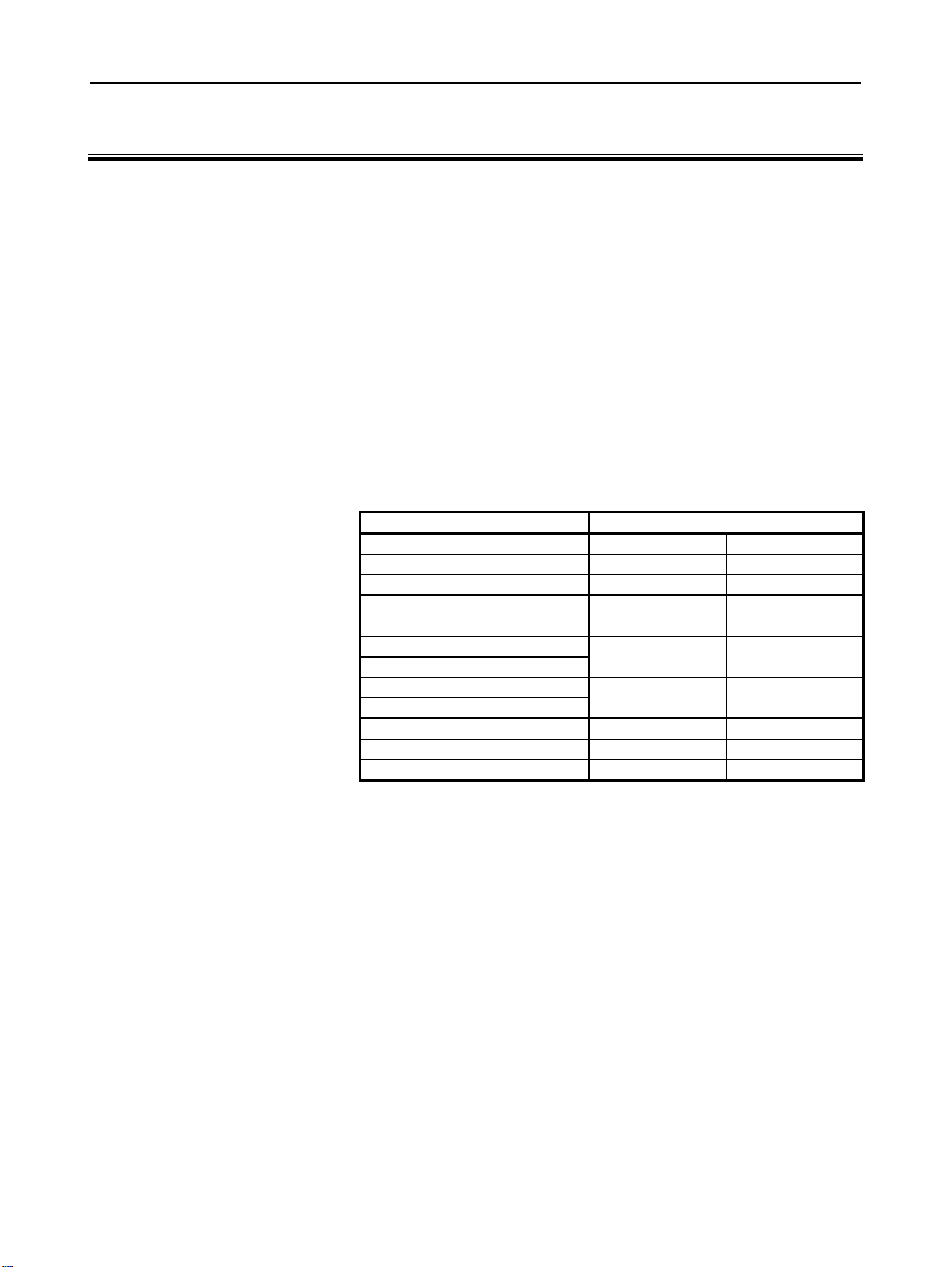
This manual consists of chapters 1 to 13 and appendixes at the end of
the book.
Chapter and title Contents
Chapter 1
CONFIGURATION
Chapter 2
TOTAL CONNECTION
DAIGRAMS
Chapter 3
INSTALLATION
Chapter 4
POWER SUPPLAY
CONNECTION
Chapter 5
CONNECTION TO CNC
PERIOHERALS
Chapter 6
SPINDLE CONNECTION
Chapter 7
SERVO INTERFACE
Chapter 8
CONNECTION TO FANUC I/O
Link
Chapter 9
STOP AND EMERGENCY
STOP
Chapter 10
CONNECTION TO OTHER
NETWORKS
Chapter 11
CONNECTION FOR Series
300is/310is/320is
Chapter 12
HIGH-SPEED SERIAL BUS
(HSSB)
Chapter 13
PANEL i
APPENDIX A) OUTLINE DRAWINGS OF UNITS
Provides general information related to the connection of the 30i series, as well as
an introduction to detailed information.
Describes how to connect peripheral units to the 30i series.
Describes the installation requirements for using the 30i series.
1) Required power supply capacity
2) Heat output
3) Locations of connectors on the control unit
4) Action against noise
Describes how to make connections related to the power supply of the 30i series.
Describes how to connect the following peripheral devices to the 30i series:
1) Display unit / MDI unit
2) I/O device (RS-232-C)
3) High-speed skip (HDI)
4) Embedded Ethernet
Describes how to connect spindle-related units to the 30i series.
Describes how to connect servo-related units to the 30i series.
Describes how to connect machine interface I/O with the FANUC I/O Link.
Describes how to handle the emergency stop signal.
Be sure to read this chapter.
Describes how to connect the 30i series to networks.
Describes connection for Series 300is/310is/320is.
Describes the high–speed serial bus (HSSB) that can be used with the 30i series.
Describes how to connect a PANEL i to the 30i series.
B) 20-PIN INTERFACE CONNECTORS AND CABLES
C) CONNECTION CABLE (SUPPLIED FROM US)
D) OPTICAL FIBER CABLE
E) LIQUID CRYSTAL DISPLAY (LCD)
F) MEMORY CARD INTERFACE
p-2
Page 7

B-63943EN/02 PREFACE
Related manuals of
Series 30i/300i/300is- MODEL A
Series 31i/310i/310is- MODEL A
Series 31i/310i/310is- MODEL A5
Series 32i/320i/320is- MODEL A
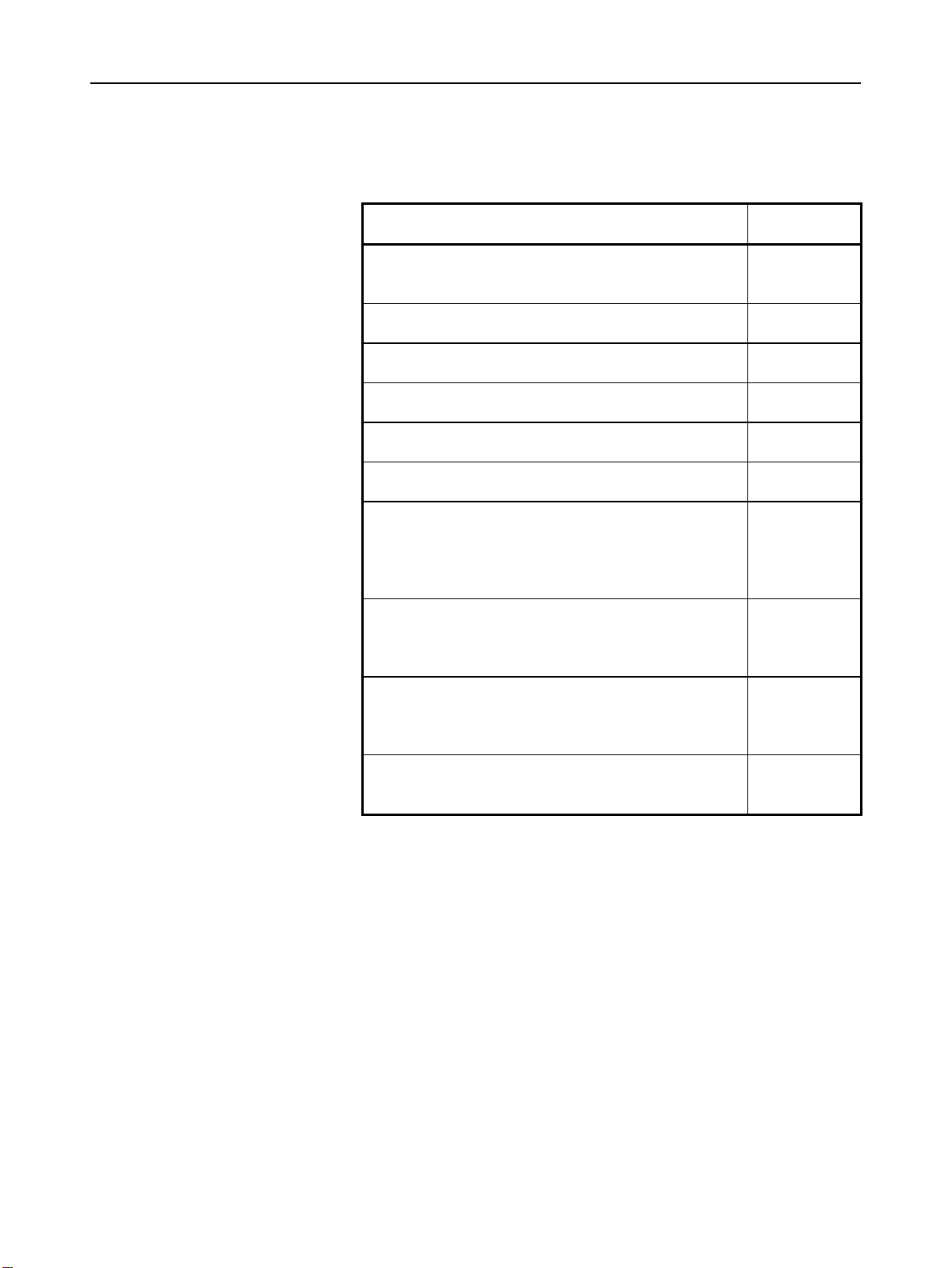
The following table lists the manuals related to Series 30i/300i
/300is-A, Series 31i/310i /310is-A, Series 31i/310i /310is-A5, Series
32i/320i /320is-A. This manual is indicated by an asterisk(*).
Table 1 Related manuals
Manual name Specification
number
DESCRIPTIONS B-63942EN
CONNECTION MANUAL (HARDWARE) B-63943EN *
CONNECTION MANUAL (FUNCTION) B-63943EN-1
USER’S MANUAL
(Common to Lathe System/Machining Center System)
USER’S MANUAL (For Lathe System) B-63944EN-1
USER’S MANUAL (For Machining Center System) B-63944EN-2
MAINTENANCE MANUAL B-63945EN
PARAMETER MANUAL B-65950EN
Programming
Macro Compiler / Macro Executor
PROGRAMMING MANUAL
Macro Compiler OPERATOR’S MANUAL B-66264EN
C Language Executor OPERATOR’S MANUAL B-63944EN-3
PMC
PMC PROGRAMMING MANUAL B-63983EN
Network
PROFIBUS-DP Board OPERATOR’S MANUAL B-63994EN
Fast Ethernet / Fast Data Server OPERATOR’S MANUAL B-64014EN
DeviceNet Board OPERATOR’S MANUAL B-64044EN
Operation guidance function
MANUAL GUIDE i OPERATOR’S MANUAL
MANUAL GUIDE i Set-up Guidance
OPERATOR’S MANUAL
B-63944EN
B-63943EN-2
B-63874EN
B-63874EN-1
p-3
Page 8
PREFACE B-63943EN/02
Related manuals of SERVO MOTOR αis/αi/βis/βi series
The following table lists the manuals related to SERVO MOTOR
αis/αi/βis/βi series
Table 2 Related manuals
Manual name
FANUC AC SERVO MOTOR αis series
FANUC AC SERVO MOTOR αi series
DESCRIPTIONS
FANUC AC SPINDLE MOTOR αi series
DESCRIPTIONS
FANUC AC SERVO MOTOR βis series
DESCRIPTIONS
FANUC AC SPINDLE MOTOR βi series
DESCRIPTIONS
FANUC SERVO AMPLIFIER αi series
DESCRIPTIONS
FANUC SERVO AMPLIFIER βi series
DESCRIPTIONS
FANUC SERVO MOTOR αis series
FANUC SERVO MOTOR αi series
FANUC AC SPINDLE MOTOR αi series
FANUC SERVO AMPLIFIER αi series
MAINTENANCE MANUAL
FANUC SERVO MOTOR βis series
FANUC AC SPINDLE MOTOR βi series
FANUC SERVO AMPLIFIER βi series
MAINTENANCE MANUAL
FANUC AC SERVO MOTOR αis series
FANUC AC SERVO MOTOR αi series
FANUC AC SERVO MOTOR βis series
PARAMETER MANUAL
FANUC AC SPINDLE MOTOR αi series
FANUC AC SPINDLE MOTOR βi series
PARAMETER MANUAL
Any of the servo motors and spindles listed above can be connected to
the CNC described in this manual. However, αi series servo amplifiers
can only be connected to αi series SVMs (for 30i/31i/32i).
This manual mainly assumes that the FANUC SERVO MOTOR αi
series of servo motor is used. For servo motor and spindle information,
refer to the manuals for the servo motor and spindle that are actually
connected.
Specification
number
B-65262EN
B-65272EN
B-65302EN
B-65312EN
B-65282EN
B-65322EN
B-65285EN
B-65325EN
B-65270EN
B-65280EN
p-4
Page 9

B-63943EN/02 TABLE OF CONTENTS
TABLE OF CONTENTS
DEFINITION OF WARNING, CAUTION, AND NOTE .................................s-1
PREFACE....................................................................................................p-1
1 CONFIGURATION ..................................................................................1
1.1 CONTROL UNIT CONFIGURATION AND COMPONENT NAMES ..............2
1.1.1 Configurations of LCD-mounted Type Control Units .............................................2
1.1.2 Configurations of Stand-alone Type Control Units..................................................5
1.1.3 Configurations of Optional Boards ..........................................................................9
1.2 HARDWARE OVERVIEW............................................................................ 11
1.2.1 LCD-mounted Type Control Unit Overview .........................................................11
1.2.2 Stand-alone Type Control Unit Overview..............................................................12
2 TOTAL CONNECTION DIAGRAMS .....................................................13
3 INSTALLATION ....................................................................................18
3.1 ENVIRONMENTAL REQUIREMENTS OUTSIDE THE CABINET............... 19
3.1.1 Environmental Conditions outside the Cabinet......................................................19
3.1.2 Installation Conditions of the CNC and Servo Unit in the Cabinet........................20
3.2 POWER SUPPLY CAPACITY .....................................................................21
3.2.1 Power Supply Capacities of CNC-related Units ....................................................21
3.3 DESIGN AND INSTALLATION CONDITIONS OF THE MACHINE TOOL
MAGNETIC CABINET ................................................................................. 23
3.4 THERMAL DESIGN OF THE MACHINE TOOL MAGNETIC CABINET ...... 25
3.4.1 Temperature Rise within the Machine Tool Magnetic Cabinet..............................25
3.4.2 Heat Output of Each Unit.......................................................................................26
3.4.3 Thermal Design of Operator's Panel.......................................................................27
3.5 ACTION AGAINST NOISE .......................................................................... 29
3.5.1 Separating Signal Lines..........................................................................................29
3.5.2 Ground....................................................................................................................31
3.5.3 Connecting the Signal Ground (SG) of the Control Unit.......................................34
3.5.4 Noise Suppressor....................................................................................................37
3.5.5 Cable Clamp and Shield Processing.......................................................................39
3.5.6 Measures Against Surges due to Lightning............................................................42
3.6 CONTROL UNIT.......................................................................................... 44
3.6.1 Installing the LCD-mounted Type Control Unit ....................................................44
3.6.2 Installing the Stand-alone Type Control Unit ........................................................45
c-1
Page 10

TABLE OF CONTENTS B-63943EN/02
3.7 CABLING DIAGRAM ...................................................................................46
3.8 DUSTPROOF MEASURES FOR CABINETS AND PENDANT BOXES ...... 47
4 POWER SUPPLY CONNECTION......................................................... 48
4.1 GENERAL ................................................................................................... 49
4.2 TURNING ON AND OFF THE POWER TO THE CONTROL UNIT............. 50
4.2.1 Power Supply for the Control Unit.........................................................................50
4.2.2 External 24 VDC Power Specification and Circuit Configuration.........................51
4.2.3 Power-on Sequence ................................................................................................55
4.2.4 Power-off Sequence ...............................................................................................55
4.3 CABLE FOR POWER SUPPLY TO CONTROL UNIT ................................. 57
4.4 BATTERIES................................................................................................. 58
4.4.1 Battery for Memory Backup in the CNC Control Unit (3 VDC)...........................58
4.4.1.1 Replacing the lithium battery............................................................................. 59
4.4.2 Batteries for PANEL i (3VDC)..............................................................................64
4.4.3 Battery for Separate Absolute Pulse Coders (6VDC) ............................................66
4.4.4 Battery for Absolute Pulse Coder Built into the Motor (6VDC)............................68
5 CONNECTION TO CNC PERIPHERALS .............................................69
5.1 CONNECTION WITH THE DISPLAY/MDI UNIT
(LCD- MOUNTED TYPE 30i SERIES) ........................................................70
5.1.1 Ovoerview ..............................................................................................................70
5.1.2 Connection to the MDI Unit (LCD-mounted Type 30i Series)..............................70
5.1.3 Connection with the Standard MDI Unit................................................................71
5.1.4 Key Layout of MDI................................................................................................72
5.2 CONNECTION WITH THE DISPLAY/MDI UNIT
(STAND-ALONE TYPE 30i SERIES) ..........................................................75
5.2.1 Overview ................................................................................................................75
5.2.2 Connection with an LCD Unit................................................................................75
5.3 CONNECTION WITH INPUT/OUTPUT DEVICES ......................................78
5.3.1 Overview ................................................................................................................78
5.3.2 Connecting I/O Devices .........................................................................................79
5.3.3 RS-232-C Serial Port..............................................................................................81
5.3.4 RS-232-C Interface Specification...........................................................................83
5.3.5 FANUC Handy FILE .............................................................................................92
5.4 CONNECTING THE HIGH-SPEED SKIP (HDI)........................................... 93
5.4.1 Connecting the High-speed Skip (HDI) .................................................................93
5.4.2 Input Signal Rules for the High-speed Skip (HDI) ................................................95
c-2
Page 11

B-63943EN/02 TABLE OF CONTENTS
5.5 Linking The EMBEDDED Ethernet Interface ............................................... 96
5.5.1 Connection to the Ethernet Interface......................................................................96
5.5.2 Specification of Twisted-Pair Cable.......................................................................98
5.5.3 Anti-Noise Measure .............................................................................................101
5.5.4 Network Installation .............................................................................................101
6 SPINDLE CONNECTION ....................................................................103
6.1 SERIAL SPINDLE...................................................................................... 104
6.1.1 Connection of One to Two Serial Spindles..........................................................104
6.1.2 Connecting One to Four Serial Spindles..............................................................107
6.1.3 Connecting Five or Six Serial Spindles................................................................114
6.1.4 Connecting Seven or Eight Serial spindles ..........................................................115
7 SERVO INTERFACE........................................................................... 116
7.1 CONNECTION TO THE SERVO AMPLIFIERS......................................... 117
7.1.1 Overview ..............................................................................................................118
7.1.2 Interface to the Servo Amplifiers .........................................................................118
7.2 SEPARATE DETECTOR INTERFACE...................................................... 121
7.2.1 Separate Detector Interface Unit Specification ....................................................123
7.2.2 Connection of Power Supply................................................................................124
7.2.3 Separate Detector Interface (Serial Interface) ......................................................126
7.2.4 Separate Detector Interface (Parallel interface)....................................................128
7.2.5 Input Signal Requirements (Parallel interface) ....................................................130
7.2.6 Connection of Battery for Absolute Position Detector.........................................132
7.2.7 Connection Between the Basic Unit and Additional Unit....................................134
7.2.8 Connector Locations.............................................................................................135
7.2.9 Installation............................................................................................................136
7.2.10 Notes on Installing a Separate Detector Interface Unit ........................................137
7.3 ANALOG INPUT SEPARATE DETECTOR INTERFACE .......................... 139
7.3.1 Overview ..............................................................................................................140
7.3.2 Analog Input Separate Detector Interface Unit Specification..............................143
7.3.3 Connection of Power Supply................................................................................143
7.3.4 Analog Input Separate Detector Interface (Analog 1Vp-p Interface) ..................145
7.3.5 Input Signal Specifications...................................................................................146
7.3.6 Connection of Battery for Absolute Position Detector.........................................147
7.3.7 Connection Between the Analog Input Separate Detector Interface Unit and
Additional Unit.....................................................................................................148
7.3.8 Connector Locations.............................................................................................149
c-3
Page 12

TABLE OF CONTENTS B-63943EN/02
7.3.9 Installation............................................................................................................150
7.3.10 Notes on Installing an Analog Input Separate Detector Interface Unit................152
8 CONNECTION TO FANUC I/O Link ................................................... 154
8.1 OVERVIEW ............................................................................................... 155
8.2 CONNECTION........................................................................................... 156
8.2.1 Connection of FANUC I/O Link by Electric Cable.............................................158
8.2.2 Connection of FANUC I/O Link by Optical Fiber Cable ....................................159
8.2.3 Connection when Multiple Channels of FANUC I/O Links are Used.................162
8.3 UNITS THAT CAN BE CONNECTED USING FANUC I/O Link................. 173
8.4 CONNECTION OF CONNECTOR PANEL I/O MODULE.......................... 174
8.4.1 Configuration .......................................................................................................174
8.4.2 Connection Diagram.............................................................................................175
8.4.3 Module Specifications..........................................................................................176
8.4.4 DI/DO Connector Pin Assignment.......................................................................178
8.4.5 DI (Input Signal) Connection...............................................................................179
8.4.6 DO (Output Signal) Connection...........................................................................181
8.4.7 DI/DO Signal Specifications................................................................................182
8.4.8 2A Output Connector Pin Allocation...................................................................184
8.4.9 2A DO (Output Signal) Connection.....................................................................185
8.4.10 2A Output DO Signal Specifications ...................................................................186
8.4.11 Analog Input Connector Pin Allocation...............................................................187
8.4.12 Analog Input Signal Connections.........................................................................188
8.4.13 Analog Input Signal Specifications......................................................................189
8.4.14 Analog Input Specifications .................................................................................190
8.4.15 Manual Pulse Generator Connection....................................................................192
8.4.16 Cable Length for Manual Pulse Generator...........................................................193
8.4.17 Connection of Basic and Extension Modules.......................................................194
8.4.18 Module Installation...............................................................................................195
8.4.19 Other Notes...........................................................................................................200
8.4.20 Distribution I/O Setting........................................................................................204
8.5 CONNECTION OF OPERATOR'S PANEL I/O MODULE
(FOR MATRIX INPUT) .............................................................................. 206
8.5.1 Overall Connection Diagram................................................................................206
8.5.2 Power Connection ................................................................................................207
8.5.3 DI/DO Connector Pin Arrangement.....................................................................208
8.5.4 DI (General-purpose Input Signal) Connection ...................................................209
8.5.5 DI (Matrix Input Signal) Connection...................................................................211
c-4
Page 13

B-63943EN/02 TABLE OF CONTENTS
8.5.6 DO (Output Signal) Connection...........................................................................212
8.5.7 Manual Pulse Generator Connection....................................................................215
8.5.8 External View.......................................................................................................216
8.5.9 Specifications .......................................................................................................217
8.5.10 Other Notes...........................................................................................................219
8.6 CONNECTION OF OPERATOR'S PANEL I/O MODULE AND POWER
MAGNETICS CABINET I/O MODULE....................................................... 223
8.6.1 Overall Connection Diagram................................................................................223
8.6.2 Power Connection ................................................................................................224
8.6.3 DI/DO Connector Pin Arrangement.....................................................................225
8.6.4 DI (General-purpose Input Signal) Connection ...................................................226
8.6.5 DO (Output Signal) Connection...........................................................................230
8.6.6 Manual Pulse Generator Connection....................................................................232
8.6.7 External View.......................................................................................................232
8.6.8 Specifications .......................................................................................................233
8.6.9 Other Notes...........................................................................................................235
8.7 FANUC I/O LINK CONNECTION UNIT ..................................................... 239
8.7.1 Overview ..............................................................................................................239
8.7.2 Specification.........................................................................................................240
8.7.3 Connection ...........................................................................................................243
8.7.3.1 I/O Link interface ............................................................................................ 243
8.8 CONNECTING THE FANUC SERVO UNIT β SERIES WITH I/O LINK .... 246
8.8.1 Overview ..............................................................................................................246
8.8.2 Connection ...........................................................................................................246
8.8.3 Maximum Number of Units that can be Connected .............................................247
8.8.4 Address Assignment by Ladder............................................................................247
8.9 CONNECTION TO ATANDARD MACHINE OPERATOR'S PANEL.......... 248
8.9.1 Overview ..............................................................................................................248
8.9.2 Total Connection Diagram...................................................................................250
8.9.3 Each Connections.................................................................................................251
8.9.3.1 Pin assignment................................................................................................. 251
8.9.3.2 Power supply connection................................................................................. 252
8.9.3.3 I/O link connection .......................................................................................... 253
8.9.3.4 Emergency stop signal connection .................................................................. 254
8.9.3.5 Power ON/OFF control signal connection....................................................... 254
8.9.3.6 General-purpose DI signal connection ............................................................ 255
8.9.3.7 General-purpose DO signal connection........................................................... 257
8.9.3.8 Manual pulse generator connection ................................................................. 258
8.9.3.9 Connector (on the cable side) specifications ...................................................261
c-5
Page 14

TABLE OF CONTENTS B-63943EN/02
8.9.4 I/O Address...........................................................................................................262
8.9.4.1 Keyboard of main panel................................................................................... 262
8.9.4.2 Override signals............................................................................................... 263
8.9.5 I/O Mapping .........................................................................................................264
8.9.6 Outline..................................................................................................................265
8.9.6.1 Outline of main panel ......................................................................................265
8.9.6.2 Outline of sub panel A..................................................................................... 266
8.9.6.3 Outline of sub panel D..................................................................................... 267
8.9.6.4 Connector locations of main panel .................................................................. 268
8.9.7 Specifications .......................................................................................................269
8.9.7.1 Environmental requirement ............................................................................. 269
8.9.7.2 Order specification........................................................................................... 269
8.9.7.3 Main panel specification.................................................................................. 269
8.9.7.4 Sub panel A/D specification ............................................................................ 269
8.9.7.5 Power supply specification .............................................................................. 270
8.9.7.6 General-purpose DI signal definition .............................................................. 270
8.9.7.7 General-purpose DO signal definition............................................................. 270
8.9.8 Key Symbol Indication on Machine Operators Panel ..........................................271
8.9.8.1 Meaning of key symbols.................................................................................. 271
8.9.8.2 Detachable key top .......................................................................................... 273
8.9.9 Others ...................................................................................................................274
8.9.10 Maintenance Parts ................................................................................................277
9 STOP AND EMERGENCY STOP .......................................................278
9.1 STOP MODES........................................................................................... 279
9.2 SHUTTING OFF THE MOTOR POWER ................................................... 280
9.3 STOPPING THE SPINDLE MOTOR .........................................................281
9.4 STOPPING THE SERVO MOTOR ............................................................282
9.5 EMERGENCY STOP SIGNAL................................................................... 283
9.6 CAUTIONS ABOUT MULTIPATH CONTROL ...........................................286
10 CONNECTION TO OTHER NETWORKS ........................................... 287
11 CONNECTION FOR Series 300is/310is/320is..................................288
11.1 TOTAL CONNECTION DIAGRAMS .......................................................... 289
11.1.1 LCD-Mounted Type Series 300is/310is/320is Control Unit................................289
11.1.2 Display Unit for is Series CNC (Stand-Alone Type) ...........................................290
11.2 INSTALLATION .........................................................................................291
11.2.1 Connector Names and Connector Layout.............................................................291
11.2.1.1 LCD-mounted Type Series 300is/310is/320is................................................. 291
11.2.1.2 Display Unit for is Series................................................................................. 292
11.2.2 Environmental Conditions for Control Units .......................................................293
c-6
Page 15

B-63943EN/02 TABLE OF CONTENTS
11.2.3 Power Supply Capacity ........................................................................................294
11.3 CONNECTION TO CNC PERIPHERALS.................................................. 295
11.3.1 Main Power Input.................................................................................................295
11.3.2 Backup Unit..........................................................................................................296
11.3.3 Ethernet Interface (10BASE-T/ 100BASE-TX)...................................................300
11.3.4 Serial Port and USB Port......................................................................................308
11.3.4.1 Serial port 1 ..................................................................................................... 308
11.3.4.2 Serial port 2 ..................................................................................................... 311
11.3.4.3 USB port (rear side)......................................................................................... 313
11.3.4.4 USB port (front side) ....................................................................................... 314
11.3.5 High-speed Serial Bus (HSSB) [For Stand-alone Type]......................................315
11.3.6 Buzzer Output.......................................................................................................316
12 HIGH-SPEED SERIAL BUS (HSSB) ..................................................317
12.1 OVERVIEW ............................................................................................... 318
12.2 CAUTIONS ................................................................................................ 318
12.3 CONNECTION DIAGRAM......................................................................... 319
12.4 PERSONAL COMPUTER SPECIFICATION .............................................320
12.5 INSTALLATION ENVIRONMENT.............................................................. 320
12.6 PROCEDURE FOR INSTALLING PERSONAL COMPUTER
INTERFACE BOARDS .............................................................................. 321
12.7 HANDLING PRECAUTIONS .....................................................................321
12.8 RECOMMENDED CABLES....................................................................... 322
13 PANEL i............................................................................................... 323
13.1 OVERVIEW ............................................................................................... 324
13.2 CAUTIONS ................................................................................................ 324
13.3 TOTAL CONNECTION DIAGRAMS .......................................................... 325
13.4 SPECIFICATIONS..................................................................................... 326
13.4.1 Installation Environmental Conditions.................................................................326
13.4.2 Power Supply Specification .................................................................................328
13.4.3 Shutdown..............................................................................................................329
13.5 INSTALLATION SPACE ............................................................................ 330
13.5.1 Installation Space of the Basic Unit .....................................................................330
13.5.1.1 Installation space of the 10.4" LCD type basic unit ........................................ 330
13.5.1.2 Installation space of the 12.1" LCD type basic unit ........................................ 331
13.5.1.3 Installation space of the 15.0" LCD type basic unit ........................................ 332
13.5.2 Installation space of the HDD unit .......................................................................333
13.5.2.1 FA full keyboard and an MDI unit other than QWERTY MDI ...................... 333
13.5.2.2 When the QWERTY MDI and 10.4" LCD type basic unit are used ...............334
c-7
Page 16

TABLE OF CONTENTS B-63943EN/02
13.5.2.3 QWERTY MDI used in cases other than combination (2).............................. 334
13.5.3 Ground Terminal Connection of Units.................................................................335
13.6 PERIPHERAL EQUIPMENT AND CONNECTION .................................... 336
13.6.1 Connector Layout Diagram ..................................................................................336
13.6.2 Main Power Supply Input ....................................................................................337
13.6.3 Serial Port 1..........................................................................................................338
13.6.4 Serial Port 2..........................................................................................................340
13.6.5 Parallel Port ..........................................................................................................342
13.6.6 High-speed serial Bus (HSSB) .............................................................................344
13.6.7 Keyboard and Mouse............................................................................................345
13.6.8 Hard Disk Unit .....................................................................................................347
13.6.9 Floppy Disk Drive................................................................................................348
13.6.10 USB ....................................................................................................................350
13.6.11 Ethernet ................................................................................................................351
13.6.12 Video Port ............................................................................................................352
13.6.13 MDI ....................................................................................................................354
13.6.14 PCMCIA Card......................................................................................................355
13.6.15 PCI Extension Board............................................................................................356
13.7 Punch Panel for PANEL i .......................................................................... 358
13.7.1 Overview ..............................................................................................................358
13.7.2 Specifications .......................................................................................................358
13.7.3 Configuration .......................................................................................................359
13.7.4 Operating Environment ........................................................................................359
13.7.5 Connection to the PANEL i..................................................................................360
13.7.6 Connection to Peripheral Devices ........................................................................363
13.8 KEY CODES OF SOFT KEYS................................................................... 366
APPENDIX
A OUTLINE DRAWINGS OF UNITS ......................................................369
B 20-PIN INTERFACE CONNECTORS AND CABLES ......................... 439
B.1 BOARD-MOUNTED CONNECTORS ........................................................ 440
B.1.1 Vertical-type Connectors......................................................................................440
B.1.2 Straight and Right-angled Connectors
(for Spring and Screw-fixing Connector Housings).............................................440
B.2 CABLE CONNECTORS ............................................................................ 441
B.2.1 Strand Wire Press-mount Connector....................................................................441
B.2.2 Soldering Type Connector....................................................................................442
c-8
Page 17

B-63943EN/02 TABLE OF CONTENTS
B.3 RECOMMENDED CONNECTORS, APPLICABLE HOUSINGS, AND
CABLES .................................................................................................... 443
B.3.1 Recommended Connectors ...................................................................................444
B.3.2 Applicable Cables.................................................................................................445
C CONNECTION CABLE (SUPPLIED FROM US).................................454
D OPTICAL FIBER CABLE.................................................................... 457
E LIQUID CRYSTAL DISPLAY (LCD) ...................................................469
F MEMORY CARD INTERFACE............................................................472
c-9
Page 18

Page 19

B-63943EN/02 1.CONFIGURATION
1 CONFIGURATION
- 1 -
Page 20
1.CONFIGURATION B-63943EN/02
1.1 CONTROL UNIT CONFIGURATION AND COMPONENT
NAMES
The 30i series control units are divided into two types: the
LCD-mounted type and stand-alone type.
LCD-mounted type control units have a built-in display. Stand-alone
type control units have a separate display unit. In the following
sections, the LCD-mounted type is also referred to as the
LCD-mounted type, and the stand-alone type is also referred to as the
stand-alone type.
The configuration and component names of each type are shown in
the figures given below. This manual explains how to attach the
connectors shown in these figures to devices. The numbers in
parentheses () in the figures are keyed to the item numbers of the
descriptions in this manual. The numbers in brackets [] in the figures
are connector numbers.
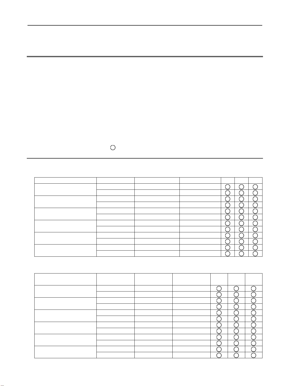
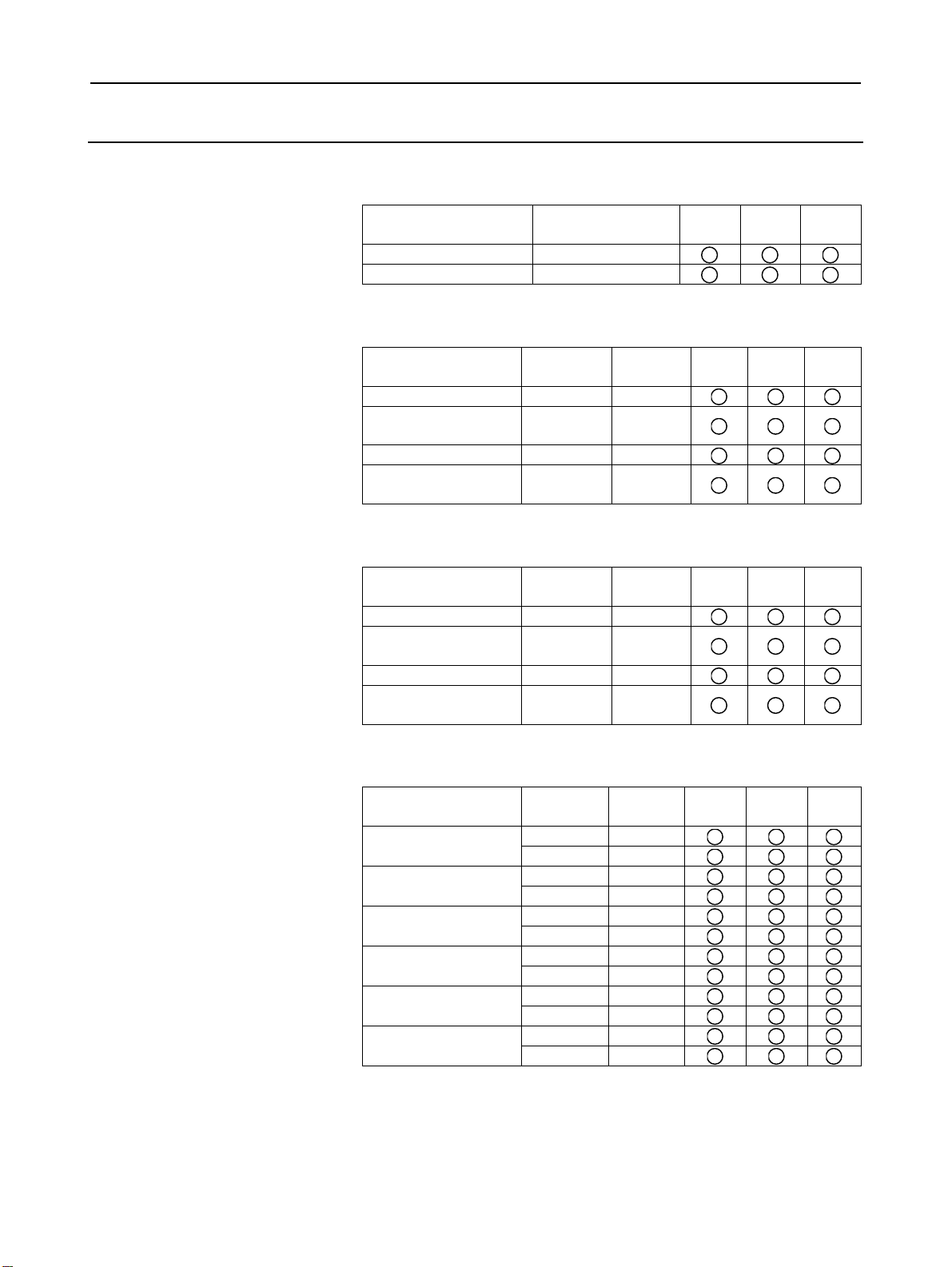
1.1.1 Configurations of LCD-mounted Type Control Units
LCD-mounted type Series 30i/31i/32i control units (A circle indicates
that the corresponding unit is available.)
Display unit Expansion slot Horizontal soft key Vertical soft key
7.2"STN monochrome LCD
8.4"TFT color LCD
10.4"TFT color LCD
10.4"TFT color LCD
(with touch panel)
15"TFT color LCD
15"TFT color LCD
(with touch panel)
None 5+2 None
2 5+2 None
None 5+2 None
2 5+2 None
None 10+2 8+1
2 10+2 8+1
None 10+2 8+1
2 10+2 8+1
None 10+2 8+1
2 10+2 8+1
None 10+2 8+1
2 10+2 8+1
LCD-mounted type Series 300is/310is/320is control units (A circle
indicates that the corresponding unit is available.)
Display unit Expansion slot
10.4"TFT color LCD
10.4"TFT color LCD
(with touch panel)
12.1"TFT color LCD
12.1"TFT color LCD
(with touch panel)
15"TFT color LCD
15"TFT color LCD
(with touch panel)
None 10+2 8+1
None 10+2 8+1
None 10+2 8+1
None 10+2 8+1
None 10+2 8+1
None 10+2 8+1
Horizontal soft
key
2 10+2 8+1
2 10+2 8+1
2 10+2 8+1
2 10+2 8+1
2 10+2 8+1
2 10+2 8+1
Vertical soft
key
30i 31i 32i
300is 310is 320is
- 2 -
Page 21
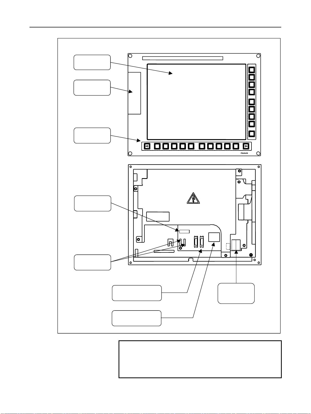
B-63943EN/02 1.CONFIGURATION
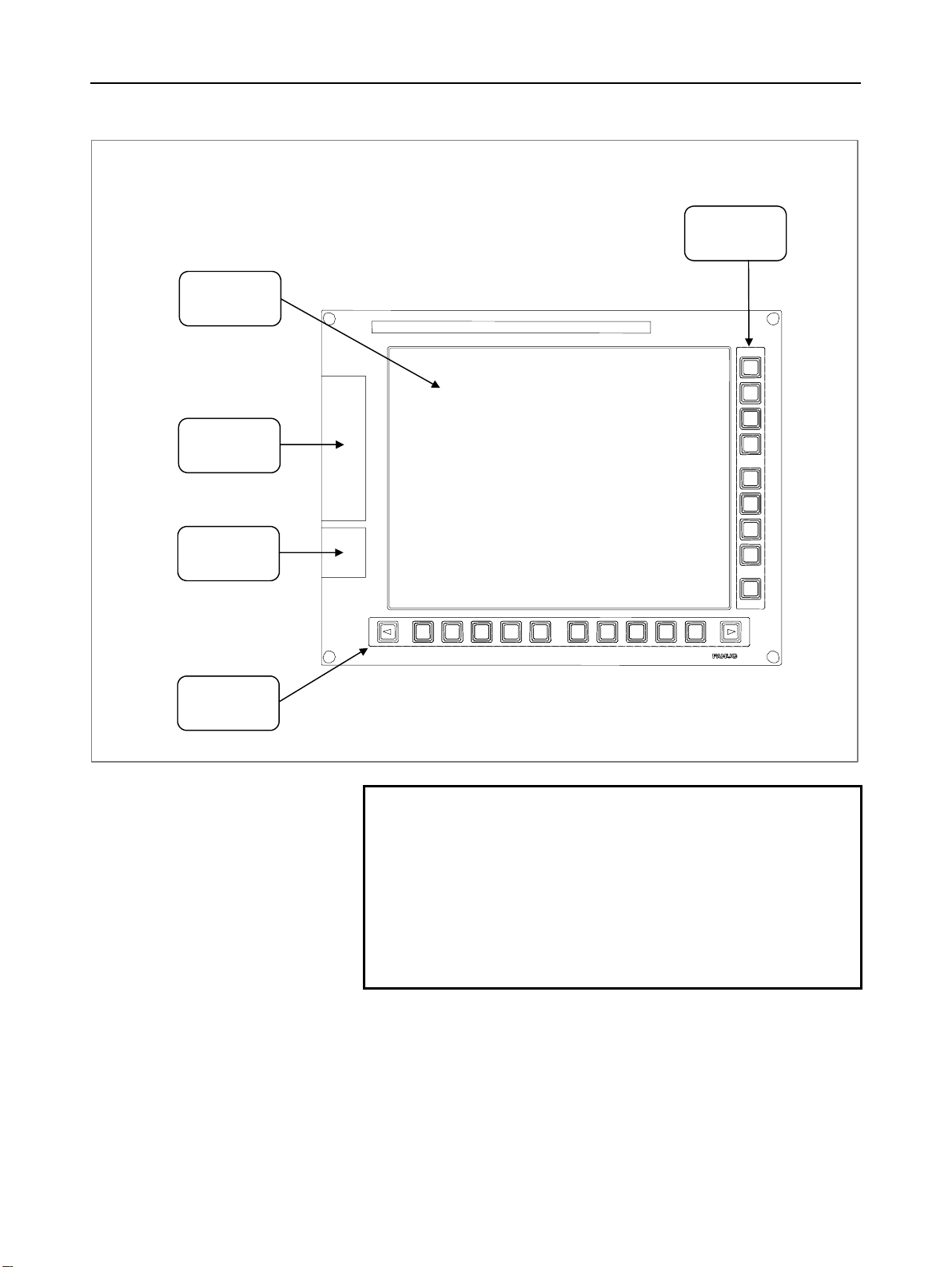
LCD-mounted type control unit
Vertical soft
keys
Liquid-crystal
display
Memory card
interface
USB port
Horizontal soft
keys
NOTE
1 This figure is a front view of the LCD-mounted type
control unit with an 10.4” TFT color liquid-crystal
display. The configurations of other control units
are basically the same as that shown above.
2 The Series 30i/31i/32i do not support the USB
port.
3 The 7.2” and 8.4” display units do not have vertical
soft keys.
- 3 -
Page 22
1.CONFIGURATION B-63943EN/02
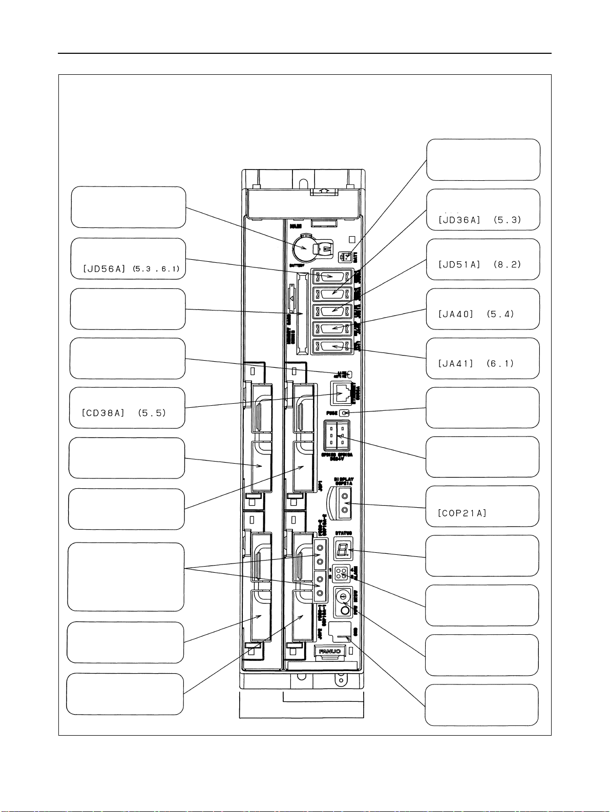
LCD-mounted type control unit
Battery
Unit rear panel
Servo unit
connector
[COP10A-1]
[COP10A-2] (7)
Fan unit
Ethernet
connector
[CD38A] (5.5)
Power supply
connector
[CPD16A]
MDI connector
[CA55] (5.1)
Soft key
I/O device interface (RS-232-C) or
serial spindle connector
[JD56A] (5.3, 6.1)
I/O device interface
connector (RS-232-C)
[JD36A/JD54] (5.3)
Power supply
module
Fuse
Serial spindle
connector
[JA41] (6.1)
I/O-Link connector
[JD51A] (8.2)
High-speed skip connector
[JA40] (5.4)
NOTE
This figure is a rear view of the 30i/31i/32i LCD-mounted type control unit without
option slots.
For the LCD-mounted type 300is/310is/320is control units, see Chapter 11.
The numbers in parentheses () in the figures are keyed to the item numbers of the
descriptions in this manual. The numbers in brackets [] in the figures are
connector numbers.
- 4 -
Page 23
B-63943EN/02 1.CONFIGURATION
1.1.2 Configurations of Stand-alone Type Control Units
Stand-alone type Series 30i/31i/32i control units (A circle indicates
that the corresponding unit is available.)
Slot rack name
2-slot rack 2
4-slot rack 4
Expansion
slot
Series 30i/31i/32i display units (A circle indicates that the
corresponding unit is available.)
Display unit
10.4"TFT color LCD 10+2 8+1
10.4"TFT color LCD
(with touch panel)
15" TFT color LCD 10+2 8+1
15" TFT color LCD
(with touch panel)
Horizontal
soft key
10+2 8+1
10+2 8+1
Vertical
soft key
Series 300i/310i/320i PANEL i (A circle indicates that the
corresponding model is available.)
Display unit
10.4"TFT color LCD 10+2 8+1
10.4"TFT color LCD
(with touch panel)
15" TFT color LCD 10+2 8+1
15" TFT color LCD
(with touch panel)
Horizontal
soft key
10+2 8+1
10+2 8+1
Vertical
soft key
Series 300is/310is/320is CNC display units (A circle indicates that the
corresponding unit is available.)
Display unit
10.4"TFT color LCD
10.4"TFT color LCD
(with touch panel)
12.1"TFT color LCD
12.1"TFT color LCD
(with touch panel)
15"TFT color LCD
15"TFT color LCD
(with touch panel)
Horizontal
soft key
10+2 8+1
10+2 8+1
10+2 8+1
10+2 8+1
10+2 8+1
10+2 8+1
10+2 8+1
10+2 8+1
10+2 8+1
10+2 8+1
10+2 8+1
10+2 8+1
Vertical
soft key
30i 31i 32i
30i 31i 32i
30i 31i 32i
300is 310is 320is
- 5 -
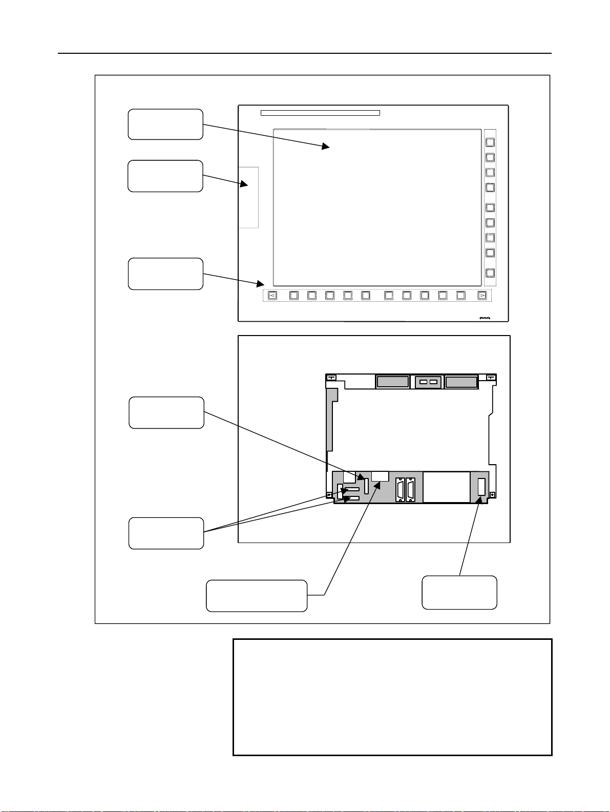
Page 24
1.CONFIGURATION B-63943EN/02
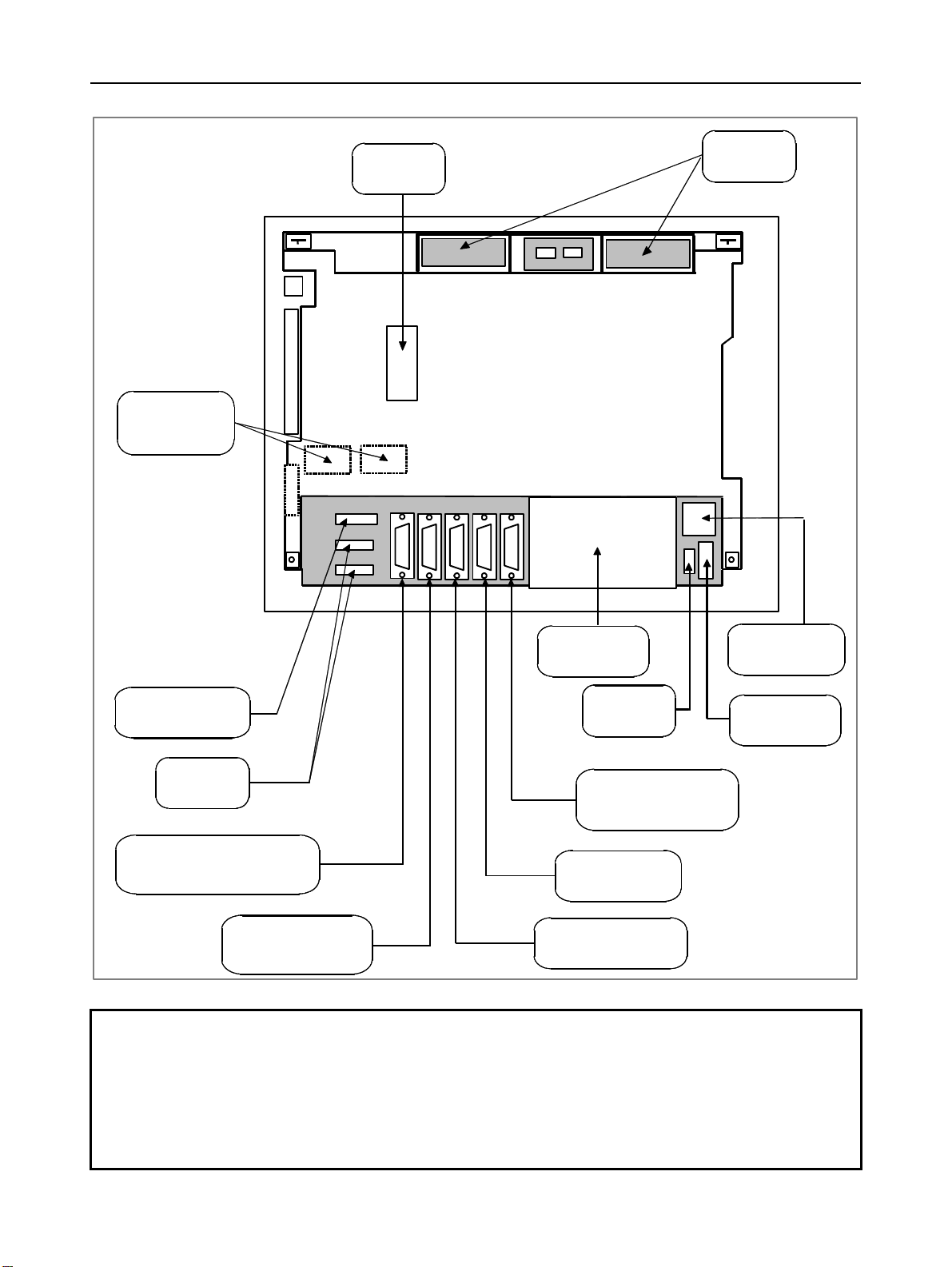
Stand-alone type control unit
Battery connector
Battery
I/O device interface
connector
Memory card interface
Ethernet LED
Ethernet connector
Optional slot 3
I/O device interface
connector
I/O Link connector
High-speed skip connector
Serial spindle connector
LED for blown fuse check
24-VDC power supply connector
[CPD19A] (right)
[CPD19B] (left)
Optional slot 1
Servo unit (FSSB)
connector
[COP10A-1] (lower)
[COP10A-2] (upper)
(7)
Optional slot 4
Optional slot 2
Display connector
2-slot rack
4-slot rack
LED for status indication
and maintenance
LED for alarm indication
Rotary switch for maintenance (upper),
Push switch for maintenance (lower)
GND connection terminal
- 6 -
Page 25
B-63943EN/02 1.CONFIGURATION
10.4” LCD unit for the stand-alone type Series 30i/31i/32i control unit
Liquid-crystal
display
Memory card
interface
Soft keys
MDI connector
[CA55] (5.1)
Soft key
connectors
Touch panel connector
Optical connector for
display control
[COP21A] (5.2)
Power supply
connectors
[CP1A]
[CP1B] (5.2)
NOTE
The numbers in parentheses () in the figures are
keyed to the item numbers of the descriptions in
this manual. The numbers in brackets [] in the
figures are connector numbers.
- 7 -
Page 26
1.CONFIGURATION B-63943EN/02
w
15” LCD unit for the stand-alone type Series 30i/31i/32i control unit
Liquid-crystal
display
Memory card
interface
Soft keys
MDI connector
[CA55] (5.1)
Soft key
connectors
Optical connector for
display control
[COP21M] (5.2)
Fan motor
Rear vie
Fan motor
Power supply
connector
[CPD18] (5.2)
NOTE
The numbers in parentheses () in the figures are
keyed to the item numbers of the descriptions in
this manual. The numbers in brackets [] in the
figures are connector numbers.
For the display units for the Series 300i/310i/320i,
see Chapter 13. For the display units for the
Series 300is/310is/320is, see Chapter 11.
- 8 -
Page 27
B-63943EN/02 1.CONFIGURATION
[
]
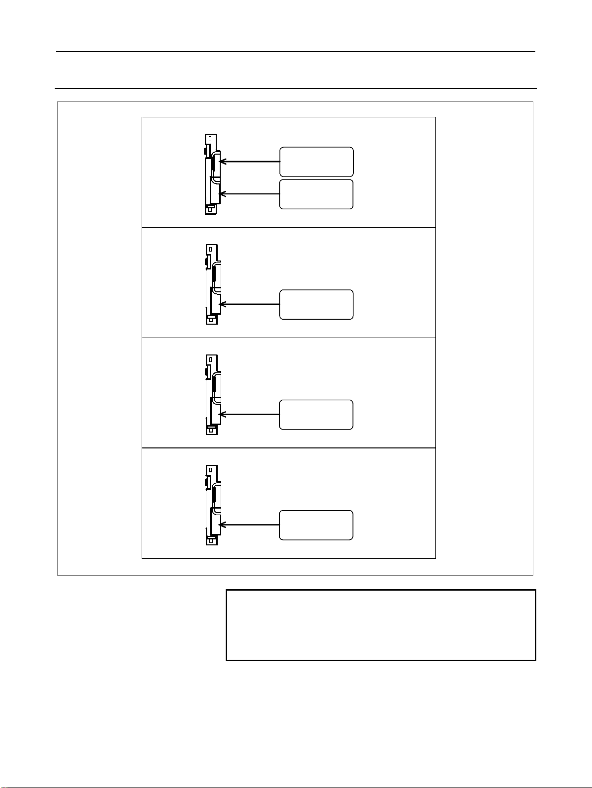
1.1.3 Configurations of Optional Boards
Additional axis board
For I/O-Link
[JD1A] (8.2)
For ser vo unit
[COP10A] (7)
Additional spindle board
For serial spindle
[JA41L] (6.1)
Fast data server board
HSSB board
For Ethernet
[CD38R] (5.5)
HSSB optical
connector
COP21N
NOTE
The numbers in parentheses () in the figures are
keyed to the item numbers of the descriptions in
this manual. The numbers in brackets [] in the
figures are connector numbers.
- 9 -
Page 28
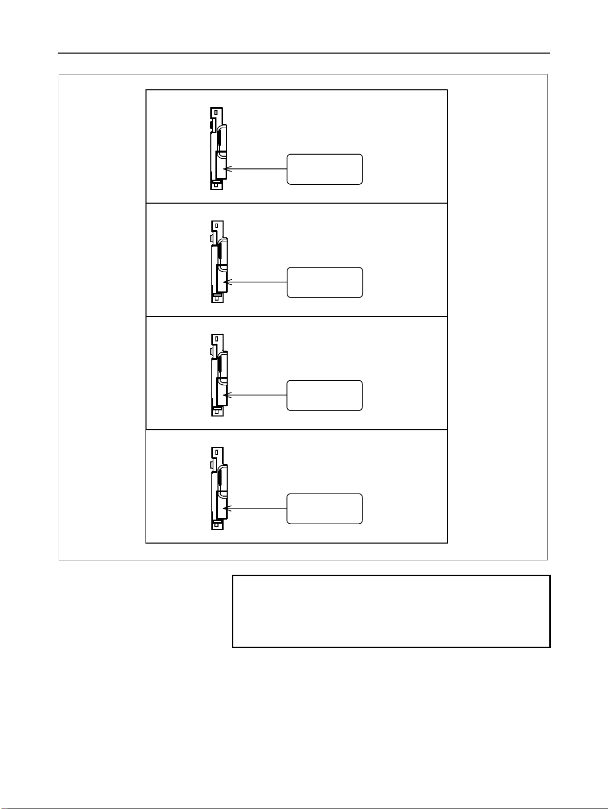
1.CONFIGURATION B-63943EN/02
Profibus master board
For Profibus
[CN1]
Profibus slave board
For Profibus
[CN2]
DeviceNet board
FL-net board
For DeviceNet
[TBL]
For FL-net
[CD38N]
NOTE
The numbers in parentheses () in the figures are
keyed to the item numbers of the descriptions in
this manual. The numbers in brackets [] in the
figures are connector numbers.
- 10 -
Page 29
B-63943EN/02 1.CONFIGURATION
A
A
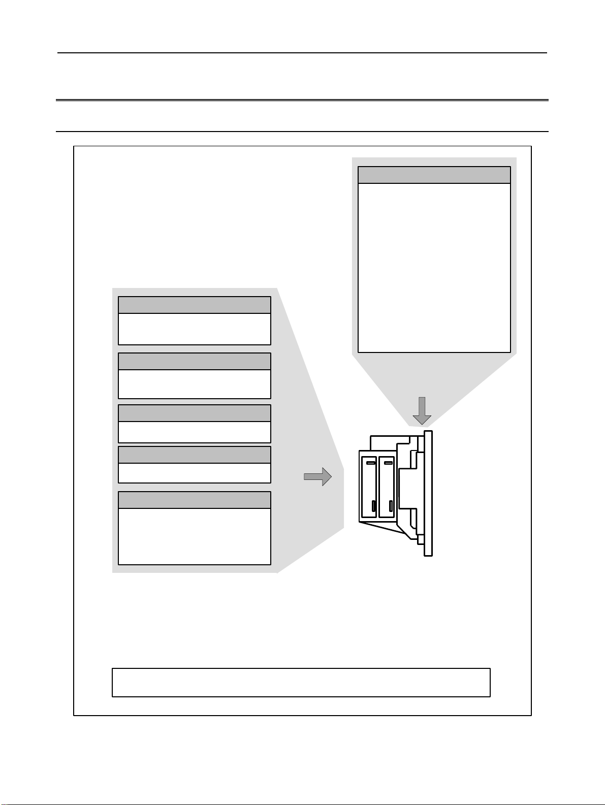
1.2 HARDWARE OVERVIEW
1.2.1 LCD-mounted Type Control Unit Overview
Main board
- CPU for controlling CNC
- Power supply
- 2-axis to 24-axis control
- Spindle interface
- LCD/MDI interface
- I/O Link
- PMC control function
- High-speed DI
- RS-232C
- Memory card interface
- PC function
300is/310is/320is)
(
Data server board
Data server function
Ethernet communication function
Additional axis board
dditional axis control function
I/O Link
Additional spindle board
dditional spindle control function
HSSB interface board
High-speed serial bus interface
Various types of network boards
FL-net board
Profibus master board
Profibus slave board
Device Net board
Basic system
Options
Unit without optional slots
or
Unit having two optional slots
On a unit with optional slots, as many optional boards as the slots can be mounted.
- 11 -
Page 30
1.CONFIGURATION B-63943EN/02
A
A
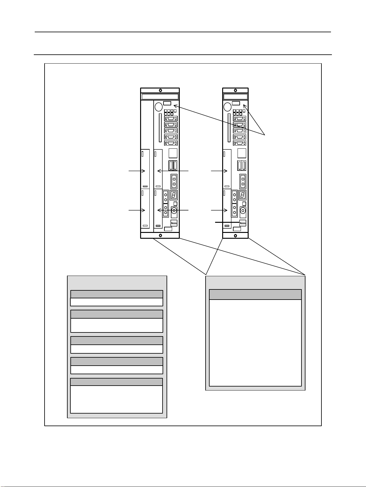
1.2.2 Stand-alone Type Control Unit Overview
2 slot rack 4 slot rack
Main board
Slot 3
Slot 4
Options (Slot 1 to 4)
Data server board
Data server function
Additional axis board
dditional axis control function
I/O Link
Additional spindle board
dditional spindle control function
HSSB interface board
High-speed serial bus interface board
Slot 1
Slot 2
Basic system
Main board
- CPU for controlling CNC
- Power supply
- 2-axis to 24-axis control
- Spindle interface
- DISPLAY interface
- I/O Link
- PMC control function
- High-speed DI
- RS-232C
- Memory card interface
Various types of network boards
FL-net board
Profibus master board
Profibus slave board
Device Net board
- 12 -
Page 31

B-63943EN/02 2.TOTAL CONNECTION DIAGRAMS
2 TOTAL CONNECTION DIAGRAMS
- 13 -
Page 32

2.TOTAL CONNECTION DIAGRAMS B-63943EN/02
p
A
A
r
LCD-mounted type control unit
LCD display unit
Main board
24V-IN(CPD16A)
MDI(CA55)
R232-1(JD56A)
R232-2(JD36A)
HDI(JA40)
I/O Link(JD51A)
SPDL(JA41)
24VDC
24VDC
3rd and 4th
serial
spindles
MDI UNIT
CK27
RS-232-C I/O unit
5th and 6th serial spindles
RS-232-C I/O unit
Touch panel
High-peed skip input
Distributed I/O
board
JA3
CPD1
JD1B
JD1A
CPD1
Distributed
I/O board,
JD1B
I/O unit, etc.
JD1A
CX1A
TB2
PSM
TB1
CX1B
C reacto
CX3
CX4
JX1B
24 VDC power supply
Manual pulse generator
Operator's
anel
Power
magnetics
cabinet
Circuit breaker
200VAC
MCC
Position coder
200VAC
Circuit breaker
FSSB(COP10A-1)
FSSB(COP10A-2)
ETHERNET(CD38A)
To 2nd spindle
24VDC
CX1A
JA7B
JA7A
COP10B
COP10A
COP10B
COP10A
COP10B
COP10A
COP10B
COP10A
(In this figure, a 1-axisamplifier is used.)
Separate detector interface unit 1
CP11A
COP10B
COP10A
CNF1
Separate detector interface unit 2
CP11A
Ethernet
CX2A
TB1
SPM
TB1
CX2B
CX2A JX1A
TB1
SVM
TB1 CX2B
SVM
SVM
SVM
JF101
JF102
JF103
JF104
JA4A
JF101
JF102
JF103
JF104
JX1A
JY2
TB2
JX1B
Serial spindle mot or
TB2
JF1
JX1B
Linear scale, axis 1
Linear scale, axis 2
Linear scale, axis 3
Linear scale, axis 4
bsolute scale battery
(Required only when an absolute scale is used)
Linear scale, axis 1
Linear scale, axis 2
Linear scale, axis 3
Linear scale, axis 4
Servo motor
Servo motor
Servo motor
Servo motor
- 14 -
Page 33

B-63943EN/02 2.TOTAL CONNECTION DIAGRAMS
β
A
A
A
A
A
Stand-alone type control unit
Main board
Slot 1
24V-IN(CPD19A)
24V-OUT(CPD19B)
DISPLAY(COP21A)
HDI(JA40)
I/O Link(JD51A)
To I/O device
Optical fiber ccable
24VDC
DC24V
DC24V
LCD UNIT
COP21A,B,M
CA55 CK27
CP1A
CP1B
(Touch panel)
High-peed skip input
Distributed
I/O board
JA3
CPD1
JD1B
JD1A
Distributed
CPD1
I/O board,
JD1B
I/O unit,
JD1A
etc.
JD1B
amplifier
with I/O Link
JD1A
Memory card
24 VDC power supply
MDI UNIT
PANEL i or personal computer
Manual pulse generator
Operator's
panel
Power
magnetics
cabinet
Servo motor
R232-1(JD56A)
R232-2(JD36A)
SPDL(JA41)
Servo card
FSSB(COP10A-1)
FSSB(COP10A-2)
ETHERNET(CD38A)
3rd, 4th
spindles
To 2nd spindle
Optical fiber cable
24VDC
Separate detector
interface unit 2
5th, 6th spindles
CX1A
TB2
PSM
TB1
CX1B
CX1A
JA7B
JA7A
COP10B
COP10A
COP10B
COP10A
COP10B
COP10A
COP10B
COP10A
(In this figure, a 1-axis amplifier is used.)
Separate detector interface unit 1
CP11A
COP10B
COP10A
CNF1
Ethernet
CX2A JX1A
TB1
SPM
TB1
CX2B JX1B
CX2A JX1A
TB1
SVM
TB1 CX2B
SVM
SVM
SVM
JF101
JF102
JF103
JF104
JA4A
RS-232-C I/O device
RS-232-C I/O device
C reactor
CX3
CX4
JX1B
JY2
TB2
TB2
JF1
JX1B
MCC
Position coder
Serial spindle mot or
Linear scale, axis 1
Linear scale, axis 2
Linear scale, axis 3
Linear scale, axis 4
Battery for absolute scale
(Required only when an absolute scale is used)
Circuit breaker
200VAC
200VAC
Circuit breaker
xis 1
servo motor
xis 2
servo motor
xis 3
servo motor
xis 4
servo motor
- 15 -
Page 34

2.TOTAL CONNECTION DIAGRAMS B-63943EN/02
A
A
When optional functions are provided
dditional spindle board
Optional slot
SPDL(JA41L)
dditional axis board
FSSB(COP10A-3)
To 8th spindle
COP10B
COP10A
COP10B
COP10A
COP10B
COP10A
COP10B
COP10A
PSM
SPM
SVM
SVM
SVM
SVM
Position coder
7th spindle
Servo motor
Servo motor
Servo motor
Servo motor
Manual pulse generator
Operator's
panel
Power
magnetics
cabinet
I/O Link(JD1A)
24VDC
24VDC
Distributed
I/O board
CPD1
JD1B
JD1A
CPD1
JD1B
JD1A
JA3
Distributed I/O
board, I/O unit,
etc.
- 16 -
Page 35

B-63943EN/02 2.TOTAL CONNECTION DIAGRAMS
A
A
A
When optional functions are provided
Fast data server
Optional slot
board
ATA card
ETHERNET(CD38R)
HSSB ボード
HSSB(COP21N)
Profibus master
board
Profibus slave
board
PROFI(CN1)
PROFI(CN2)
The user should provide an ATA card.
Ethernet
Personal Computer
or PANEL i
nother NC
(another Profibus unit)
nother NC
(another Profibus unit)
(Note 1)
DeviceNet board
DVNET(TBL)
FL-net board
FLNET(CD38N)
nother NC
(another DeviceNet unit)
FL-net unit
Note 1 The 30i/31i/32imodel is still used when a
personal computer or PANEL i is
connected using an HSSB interface.
- 17 -
Page 36

3.INSTALLATION B-63943EN/02
3 INSTALLATION
- 18 -
Page 37

B-63943EN/02 3.INSTALLATION
3.1 ENVIRONMENTAL REQUIREMENTS OUTSIDE THE
CABINET
3.1.1 Environmental Conditions outside the Cabinet
The peripheral units and the control unit have been designed on the
assumption that they are housed in closed cabinets. In this manual
"cabinet" refers to the following:
• Cabinet manufactured by the machine tool builder for housing
the control unit or peripheral units;
• Operation pendant, manufactured by the machine tool builder,
for housing the LCD/MDI unit or operator's panel.
• Equivalent to the above.
The environmental conditions when installing these cabinets shall
conform to the following table. Section 3.3 describes the installation
and design conditions of a cabinet satisfying these conditions.
Ambient
temperature of
the cabinet
Humidity
Vibration
sea level
Environment
NOTE
If the CNC is installed 1000 m or higher above sea level, the allowable upper
ambient temperature of the CNC in the cabinet is changed as follows.
Assume that the allowable upper ambient temperature of the CNC in the cabinet
installed 1000 m or higher above sea level decreases by 1.0°C for every 100 m rise
in altitude.
Example)
The upper allowable ambient temperature of the CNC in the cabinet installed
1750 m above sea level is:
55°C - 1750/100 × 1.0°C = 47.5°C
Therefore, the allowable ambient temperature range is from 0°C to 47.5°C.
When a hard disk is used, there are the following installation conditions:
Meters above sea level (operating): -60 to 3000 m
Meters above sea level (non-operating): -60 to 12000 m
Operating 0°C to 45°C
Storage, Transport -20°C to 60°C
Temperature change 0.3°C/minute or less
Normal 75%RH or less, no condensation
Short period
(less than 1 month)
Operating 0.5G or less
Non-operating 1.0G or less
Operating Up to 1000 m (Note) Meters above
Non-operating Up to 12000 m
Normal machine shop environment
(The environment must be considered if the cabinets
are in a location where the density of dust, coolant,
organic solvent, and/or corrosive gas is relatively high.)
95%RH or less, no condensation
- 19 -
Page 38

3.INSTALLATION B-63943EN/02
3.1.2 Installation Conditions of the CNC and Servo Unit in the
Cabinet
Condition
Operating 0°C to 58°C 0°C to 55°C
Ambient
temperature
Humidity
Vibration
above sea
level
Environment
Storage,
Transport
Temperature
change
Normal 75%RH or less, no condensation
Short period
(less than 1
month)
Operating
Non-operating 1.0G or less
Operating Up to 1000 m (Note in Subsection 3.1.1) Meters
Non-operating Up to 12000 m
LCD-mounted type control unit
and display unit
−20°C to 60°C
0.3°C/minute or less
95%RH or less, no condensation
0.5G or less
FANUC conducted an evaluation test under the
following conditions:
10 to 58 Hz: 0.075 mm (amplitude)
58 to 500Hz: 1G
Direction of vibration: Each of the X, Y, and Z directions
Number of sweep cycles: 10
Conforming to IEC68-2-6
Coolant, lubricant, or cutting chips shall not be sprinkled
directly over the CNC or servo unit. No corrosive gas
shall be allowed.
NOTE
If you want to use a PANEL i, see also Chapter 13.
Stand-alone type
control unit
- 20 -
Page 39

B-63943EN/02 3.INSTALLATION
3.2 POWER SUPPLY CAPACITY
3.2.1 Power Supply Capacities of CNC-related Units
The following CNC-related units require an input power supply that
satisfies the indicated current capacities with a power supply voltage
of 24 VDC ±10%. Here, note that momentary voltage changes and
ripples are also within ±10% of the power supply voltage.
Table 3.2.1 (a) Power supply capacity
Power
Unit
7.2”/8.4”/10.4” type display unit
type control
unit
Stand-alone
type control
unit
Optional board
15” type display unit
Control unit (alone)
10.4” display unit
15” display unit
Additional axis board
Additional spindle board
Fast data server board
HSSB board
Profibus master board
Profibus slave board
FL-net board
DeviceNet (master) board
NOTE
1 The liquid-crystal display and MDI unit are
included. Optional boards are not included.
2 When an RS-232C unit (with power supplied from
the NC) is connected to the RS-232C port, +0.2 A
is further required.
3 Use memory cards that consume no more than 2
W.
4 For the PANEL i, see Chapter 13.
5 For the FS300i/310is/320is, see Chapter 11.
6 For other peripheral units (such as I/O units), see
Table 3.2.1 (b) and also refer to the relevant
manuals.
7 When you select the input DC power supply for the
CNC control section, consider the restrictions other
than the power supply capacity. Be sure to see
also Subsection 4.4.2.
supply
capacity
1.6A
2.2A
1.6A
0.7A
1.5A
0.3A
0.2A
0.2A
0.2A
0.2A
0.1A
0.2A
0.1A
Remarks
Note 1) LCD-mounted
Note 1)
- 21 -
Page 40

3.INSTALLATION B-63943EN/02
Table 3.2.1 (b) Power supply rating (peripheral units)
Unit
MDI unit 0A
Standard machine operator’s panel 0.4A
Operator's panel I/O module 0.3A+7.3mA×DI
Connector panel I/O module (basic) 0.2A+7.3mA×DI
Connector panel I/O module
(additional)
Separate detector interface unit 0.9A Basic 4-axis unit
Separate detector interface unit 1.5A Basic 4 axes +
Power supply
capacity
0.1A+7.3mA×DI
Remarks
only
additional 4 axes
- 22 -
Page 41

B-63943EN/02 3.INSTALLATION
3.3 DESIGN AND INSTALLATION CONDITIONS OF THE
MACHINE TOOL MAGNETIC CABINET
When a cabinet is designed, it must satisfy the environmental
conditions described in Section 3.1. In addition, the magnetic
interference on the screen, noise resistance, and maintenance
requirements must be considered. The cabinet design must meet the
following conditions :
(1) The cabinet must be fully closed.
The cabinet must be designed to prevent the entry of airborne
dust, coolant, and organic solvent.
(2) The cabinet must be designed so that the permissible temperature
of each unit is not exceeded. For actual heat design, see Section
3.4.
(3) A closed cabinet must be equipped with a fan to circulate the air
within. (This is not necessary for a unit with fan.)
The fan must be adjusted so that the air moves at 0.5 m/sec along
the surface of each installed unit.
CAUTION
If the air blows directly from the fan to the unit, dust
easily adheres to the unit. This may cause the
unit to fail. (This is not necessary for a unit with
fan.)
(4) For the air to move easily, a clearance of 100 mm is required
between each unit and the wall of the cabinet.
(5) Packing materials must be used for the cable port and the door in
order to seal the cabinet.
(6) The display unit must not be installed in such a place that coolant
would directly fall onto the unit. The control unit has a
dust-proof front panel, but the unit should not be placed in a
location where coolant would directly fall onto it.
(7) Noise must be minimized.
As the machine and the CNC unit are reduced in size, the parts
that generate noise may be placed near noise-sensitive parts in
the magnetics cabinet.
The CNC unit is built to protect it from external noise. Cabinet
design to minimize noise generation and to prevent it from being
transmitted to the CNC unit is necessary. See section 3.5 for
details of noise elimination/management.
(8) When placing units in the cabinet, also consider ease of
maintenance.
The units should be placed so that they can be checked and
replaced easily when maintenance is performed.
(9) The hard disk drive and floppy disk drive must not be installed
near the source of a strong magnetic field.
(10) The installation conditions of the I/O unit and connector panel
I/O module must be satisfied.
- 23 -
Page 42

3.INSTALLATION B-63943EN/02
To obtain good ventilation in the module, the I/O unit and
connector panel I/O module must be installed in the direction
shown in the following figure. Clearances of 100 mm or more
both above and below the I/O unit are required for wiring and
ventilation.
Equipment radiating too much heat must not be put below the
I/O unit and connector panel I/O module.
Top
Bottom
Connector panel I/O module or
I/O base unit
(No screws or protrusions shall extend
from the bottom of this unit.)
- 24 -
Page 43

B-63943EN/02 3.INSTALLATION
3.4 THERMAL DESIGN OF THE MACHINE TOOL MAGNETIC
CABINET
The internal air temperature of the cabinet increases when the units
and parts installed in the cabinet generate heat. Since the generated
heat is radiated from the surface of the cabinet, the temperature of the
air in the cabinet and the outside air balance at certain heat levels.
If the amount of heat generated is constant, the larger the surface
area of the cabinet, the less the internal temperature rises. The
thermal design of the cabinet refers to calculating the heat generated in
the cabinet, evaluating the surface area of the cabinet, and enlarging
that surface area by installing heat exchangers in the cabinet, if
necessary. Such a design method is described in the following
subsections.
3.4.1 Temperature Rise within the Machine Tool Magnetic Cabinet
The cooling capacity of a cabinet made of sheet metal is generally 6
W/°C per 1m
contained in a cabinet having a surface area of 1 m
of the air in the cabinet rises by 1°C. In this case the surface area of
the cabinet refers to the area useful in cooling , that is, the area
obtained by subtracting the area of the cabinet touching the floor from
the total surface area of the cabinet. There are two preconditions :
The air in the cabinet must be circuited by the fun, and the
temperature of the air in the cabinet must be almost constant. For
example, the operator’s panel cabinet may contain an LCD-mounted
type control unit or the display of a stand-alone type control unit. To
keep the temperature in the cabinet at 58°C or below when the
ambient temperature is 45°C, the equation below must be satisfied.
Internal heat loss P [W] ≤
6[W/m
(A cooling capacity of 6 W/°C assumes the cabinet is so large that
agitation with the fan motor does not make the temperature
distribution uniform. For a small cabinet like the operator's panel, a
cooling capacity of 8 W/°C, indicated in Subsection 3.4.4, may be
used.)
For example, a cabinet having a surface area of 4m
capacity of 24W/°C. To limit the internal temperature increase to
13°C under these conditions, the internal heat must not exceed
312W. If the actual internal heat is 360W, however, the temperature
in the cabinet rises by 15°C or more. When this happens, the cooling
capacity of the cabinet must be improved using the heat exchanger.
For the power magnetic cabinet containing a stand-alone type control
unit, the internal temperature rise must be suppressed to 55°C or less,
instead of 58°C.
2
surface area, that is, when the 6W heat source is
2
⋅°C] × surface area S[m2] × 13[°C] of rise in temperature
2
, the temperature
2
has a cooling
- 25 -
Page 44

3.INSTALLATION B-63943EN/02
3.4.2 Heat Output of Each Unit
Table 3.4.2 (a) Heat output
Heat
output
33W
49W
30W
13W
34W
4W
3W
3W
4W
5W
2W
5W
2W
type control unit
Stand-alone type
control unit
Optional board
Unit
7.2”/8.4”/10.4” type display unit
15” type display unit
Control unit (alone)
10.4” display unit
15” display unit
Additional axis board
Additional spindle board
Fast data server board
HSSB board
Profibus master board
Profibus slave board
FL-net board
DeviceNet (master) board
NOTE
The liquid-crystal display and MDI unit are
included. Optional boards are not included.
Table 3.4.2 (b) Heat output
Unit
MDI unit 0W
Standard machine operator’s
panel
Operator's panel I/O module 12W Note 1)
Connector panel I/O module
(basic)
Connector panel I/O module
(additional)
Separate detector interface unit 9W Basic 4-axis unit only
Separate detector interface unit 14W Basic 4 axes + additional 4 axes
Heat
output
15W Note 1)
8W Note 1)
5W Note 1)
Note 2)
Note 2)
Remarks
NOTE
1 The indicated values are when 50% of the module
input signals are ON.
2 Heat output generated within the separate detector
is not included.
Remarks
(Note) LCD-mounted
(Note)
- 26 -
Page 45

B-63943EN/02 3.INSTALLATION
3.4.3 Thermal Design of Operator's Panel
With a small cabinet like the operator's panel, the heat dissipating
capacity of the cabinet is as shown below, assuming that there is
sufficient mixing of the air inside the cabinet.
Coated metal surfaces: 8 W/m
Plastic surfaces: 3.7 W/m
An example of the thermal design for the cabinet shown in Fig. 3.4.3
is shown below.
2
°C
2
°C
Fig. 3.4.3
Assume the following.
Thermal exchange rates
2
Coated metal surfaces : 8 W/m
Plastic surfaces : 3.7 W/m
⋅°C
2
⋅°C
Allowable temperature rise : 13°C higher than the exterior
temperature
Also, assume the following.
Dimensions of pendant type cabinet shown in Fig. 3.4.3:
560(W) × 470(H) × 150(D) mm
Surface area of metallic sections : 0.5722 m
Surface area of plastic sections : 0.2632 m
2
2
- 27 -
Page 46

3.INSTALLATION B-63943EN/02
In this case, the allowable total heat dissipation for the cabinet is:
8 × 0.5722 × 13 + 3.7 × 0.2632 × 13 = 72 W.
In consequence, it can be concluded that the units shown in Table
3.4.3 on the next page can be installed in this cabinet.
Table 3.4.3
LCD-mounted type control unit (10.4” LCD) 33W
Optional board (Fast data server board) 3W
Optional board (Additional axis board) 4W
Standard machine operator's panel 15W
120-mm square fan motor for air mixing 8W
Total heat dissipation of the above 63W
NOTE
The 15 W quoted for the standard machine
operator's panel represents an example heat
output value when half of all the input signals are
turned on. This value varies, depending on the
mechanical configuration.
- 28 -
Page 47

B-63943EN/02 3.INSTALLATION
3.5 ACTION AGAINST NOISE
The CNC has been steadily reduced in size using surface-mount and
custom LSI technologies for electronic components. The CNC also is
designed to be protected from external noise. However, it is difficult
to measure the level and frequency of noise quantitatively, and noise
has many uncertain factors. It is important to prevent both noise from
being generated and generated noise from being introduced into the
CNC. This precaution improves the stability of the CNC machine tool
system.
The CNC component units are often installed close to the parts
generating noise in the power magnetics cabinet. Possible noise
sources into the CNC are capacitive coupling, electromagnetic
induction, and ground loops.
When designing the power magnetics cabinet, guard against noise in
the machine as described in the following section.
3.5.1 Separating Signal Lines
The cables used for the CNC machine tool are classified as listed in
the following table:
Process the cables in each group as described in the action column.
Group Signal line Action
Primary AC power line
A
Secondary AC power line
AC/DC power lines (containing the power
lines for the servo and spindle motors)
AC/DC solenoid
AC/DC relay
DC solenoid (24VDC)
B
DC relay (24VDC)
DI/DO cable between the I/O unit and power
magnetics cabinet
DI/DO cable between the I/O unit and
machine
24-VDC input power cables connected to the
control unit and its peripherals
Cable between the CNC and I/O Unit
C
Cable for position and velocity feedback
Cable between the CNC and spindle
amplifier
Cable for the position coder
Cable for the manual pulse generator
Cable between the CNC and the MDI (Note
3)
RS-232C and RS-422 interface cable
Cable for the battery
Other cables to be covered with the shield
NOTE
Bind the cables in group A separately (Note 1)
from groups B and C, or cover group A with an
electromagnetic shield (Note 2).
See Section 3.5.4 and connect spark killers or
diodes with the solenoid and relay.
Connect diodes with DC solenoid and relay.
Bind the cables in group B separately from
group A, or cover group B with an
electromagnetic shield.
Separate group B as far from Group C as
possible.
It is more desirable to cover group B with the
shield.
Bind the cables in group C separately from
group A, or cover group C with an
electromagnetic shield.
Separate group C as far from Group B as
possible.
Be sure to perform shield processing in
Section 3.5.5.
- 29 -
Page 48

3.INSTALLATION B-63943EN/02
1 The groups must be 10 cm or more apart from one
another when binding the cables in each group.
2 The electromagnetic shield refers to shielding
between groups with grounded steel plates.
3 The shield is not required when the cable between
the CNC and MDI is shorter than 30 cm.
- 30 -
Page 49

B-63943EN/02 3.INSTALLATION
3.5.2 Ground
The CNC machine tool uses the following three types of grounding:
• Signal grounding
Signal grounding supplies a reference potential (0V) for electrical
signals.
• Grounding for protection
Grounding for protection is performed for safety reasons as well as
to shield against external and internal noise. This type of
grounding includes, for example, the equipment frames, cases and
panels of units, and the shielding on interface cables connecting the
equipment.
• Protective grounding (PE)
Protective grounding (PE) is performed to connect protection
grounds provided for equipment or between units to ground
together at one point as a grounding system.
One of the two grounding methods can be selected for the CNC:
(1) One-point grounding: See Fig. 3.5.2 (a).
(2) Grounding with a nearby ground plate: See Fig. 3.5.2 (b).
Fig. 3.5.2 (a) Example of one-point grounding
- 31 -
Page 50

3.INSTALLATION B-63943EN/02
Notes on grounding
Fig. 3.5.2 (b) Example of grounding with a nearby ground plate
• The ground resistance in protective grounding (PE) must be 100
Ω or less (type D grounding).
• The cable used for protective grounding (PE) must be of a
sufficient cross section to allow current to flow safely into
protective ground (PE) if an accident such as a short-circuit
occurs. (Generally, a cross section equal to or greater than that
of the AC power cable is required.)
• The cable connected to protective ground (PE) must be
incorporated into the AC power wire such that power cannot be
supplied with the ground wire disconnected.
• A wire for connecting a unit to a nearby plate (path A in Fig.
3.5.2 (b)) must be connected to the plate with the shortest
possible length. The cross section of the wire must satisfy the
IEC connections shown below. When the breaker limits an
input current, however, the wire only needs to satisfy the
requirement of current-carrying capacity of the breaker. When
cross section conditions are defined in the unit manual, the
conditions must be satisfied.
• For plate connection, use path B to connect a PE connection plate
with a unit connection plate as shown in Fig. 3.5.2 (b).
In this case, the cable thickness varies with the capacity of the
AC input power supply for the unit mounted on each metal sheet.
Therefore, when the cross-sectional area is shown in the manual
of each unit, refer the value. Otherwise, see Table 3.5.2 below.
However, when the thickness of the connection cable for
protective earthing (PE) is exceeded, the thickness of the
connection cable for protective earthing (PE) must be used.
- 32 -
Page 51

B-63943EN/02 3.INSTALLATION
Table 3.5.2 Guideline for selecting the cross-sectional area of the
protection copper cable
Rated current of the fuse for protecting
an assumed circuit or the rated current of
the overcurrent protection unit
A
30 2 or more
50 3.5 or more
100 5.5 or more
150 8 or more
225 14 or more
400 22 or more
600 38 or more
800 50 or more
1000 60 or more
1200 80 or more
1600 100 or more
2000 125 or more
2500 150 or more
3200 200 or more
4000 250 or more
Cross-sectional area of the
protection copper cable
mm
2
Rated current of the fuse for protecting an assumed circuit or the rated
current of the overcurrent protection unit
When the breaker limits a current, the cable only needs to satisfy the
requirement of current-carrying capacity of the breaker.
Connections made with welding can also be used when they allow a
sufficient current to flow.
* A ground wire for protective grounding must satisfy the
following conditions, as defined in IEC60204.
• Where the cross section of a wire of the connected input
power supply is S:
2
S ≤ 16 mm
16 mm
35 mm
2
< S ≤ 35 mm2...16 mm2
2
< S ..S / 2
...S
- 33 -
Page 52

3.INSTALLATION B-63943EN/02
A
3.5.3 Connecting the Signal Ground (SG) of the Control Unit
Connecting the 0 V output in the CNC to a protective circuit (ground)
The IEC 204-1 and JIS B 6015 standards specify the following:
- Protection against malfunctions due to ground faults
“To make the control circuit prevent malfunctions of a machine tool
due to a ground fault and not to prevent the machine tool from
stopping, either of the ground and electronic circuits shall be
connected to a protective circuit.”
Note that for each FANUC CNC, the 0V output in the CNC is
connected to a protective circuit (ground).
Machine
24 VDC power
supply
Relay
Output
signal
Power
magnetics
cabinet
NC ground terminal
This bold line indicates grounding for the control unit described in the connection manual.
s shown in this figure, by just connecting the ground terminal of the control unit to the machine ground,
the 0 V output of the relay circuit in the power magnetics cabinet is connected to the ground (protective
circuit).
Machine protective circuit (ground) network
Connection to the ground in the user factory
- 34 -
Page 53

B-63943EN/02 3.INSTALLATION
Connecting the ground terminal of an LCD-mounted type control unit
Connect the 0-V line in the control unit with the ground plate of the
cabinet or a nearby plate via the protective grounding terminal (see
above figure).
- 35 -
Page 54

3.INSTALLATION B-63943EN/02
Connecting the ground terminal of a stand-alone type control unit
For 2-slot rack
For 4-slot rack
Signal ground
terminal (Faston
terminal)
Gr ound c able
2
or more
2 mm
PE
Grounding plate of
the cabinet
Connect the 0-V lines of the electronic circuits in the control unit to
the ground plate of the cabinet via the signal ground terminal.
Use the Faston terminal (FANUC specification: A02B-0166-K330).
- 36 -
Page 55

B-63943EN/02 3.INSTALLATION
A
3.5.4 Noise Suppressor
The AC/DC solenoid and relay are used in the power magnetics
cabinet.
A high pulse voltage is caused by coil inductance when these devices
are turned on or off.
This pulse voltage induced through the cable causes the electronic
circuits to be disturbed.
Notes on selecting the spark killer
• Use a spark killer consisting of a resistor and capacitor in series.
This type of spark killer is called a CR spark killer.(Use it under
AC)
(A varistor is useful in clamping the peak voltage of the pulse
voltage, but cannot suppress the sudden rise of the pulse voltage.
FANUC therefore recommends a CR spark killer.)
• The reference capacitance and resistance of the spark killer shall
conform to the following based on the current (I (A)) and DC
resistance of the stationary coil:
(1) Resistance (R) : Equivalent DC resistance of the coil
22
II
to
(2) Capacitance (C) :
10
I : Current at stationary state of the coil
Equivalent circuit of the spark killer
(µF)
20
RC
C relay
Spark killer
Spark killer
Mount the noise eliminator near a motor or a relay coil.
NOTE
Use a CR-type noise eliminator. Varistor-type
noise eliminators clamp the peak pulse voltage but
cannot suppress a sharp rising edge.
Motor
- 37 -
Page 56

3.INSTALLATION B-63943EN/02
Diode (used for direct-current circuits)
Diode
Use a diode which can withstand a voltage up
DC relay
to two times the applied voltage and a current
up to two times the applied current.
- 38 -
Page 57

B-63943EN/02 3.INSTALLATION
3.5.5 Cable Clamp and Shield Processing
If a cable connected to the CNC, servo amplifier, spindle amplifier, or
other device requires shielding, clamp the cable as shown below.
The clamp both supports and shields the cable. Use this clamp to
ensure stable operation of the system.
Partially peel out the sheath and expose the shield. Push and clamp
by the plate metal fittings for clamp at the part. The ground plate
must be made by the machine tool builder, and set as follows :
Ground plate
Cable
Metal fittings for
clamp
40 to 80 mm
Fig. 3.5.5 (a) Cable clamp (1)
NOTE
Select a cable with a proper length.
If the cable is too long, the noise immunity may be
reduced or noise may be caused on other cables.
In addition, when the excess length is coiled, the
inductance is increased and a high voltage is
induced during turning on or off of signals. This
may cause malfunction due to a failure or noise.
- 39 -
Page 58

3.INSTALLATION B-63943EN/02
Control unit
Metal fittings
for clamp
Shield cover
Fig. 3.5.5 (b) Cable clamp (2)
Machine side
installation board
Ground plate
NOTE
Bring together the cables connected to a CNC or
amplifier near the unit and shield them.
Prepare ground plate like the following figure.
Ground terminal
(grounded)
Hole for securing metal fitting clamp
Mount screw hole
Fig. 3.5.5 (c) Ground plate
For the ground plate, use a metal plate of 2 mm or thicker, which
surface is plated with nickel.
- 40 -
Page 59

B-63943EN/02 3.INSTALLATION
8
12
20
Fig. 3.5.5 (d) Ground plate holes
Ground plate
(Reference) Outer drawings of metal fittings for clamp.
Max. 55mm
28mm
6mm
Fig. 3.5.5 (e) Outer drawings of metal fittings for clamp
Ordering specification for metal fittings for clamp
A02B-0124-K001 (8 pieces)
17mm
- 41 -
Page 60

3.INSTALLATION B-63943EN/02
3.5.6 Measures Against Surges due to Lightning
To protect the devices from surge voltages due to lightening, it is
recommended to install surge-absorbing elements between the lines of
the input power and between one line and ground. This does not,
however, assure protection from all surges due to lightening.
The recommended items are as follows. (Items made by Okaya
Denki Sangyo Co.)
For the 200-V system
Between lines R⋅A⋅V-781BYZ-2
Between line and ground R⋅A⋅V-781BXZ-4
For the 400-V system
Between lines R⋅A⋅V-152BYZ-2A
Between line and ground R⋅A⋅V-801BXZ-4
Installation procedure
The surge-absorbing elements used for measures against surges due to
lightening must be installed in the input power unit as shown in the
figure below. The figure below shows an example in which an
insulating transformer, shown by dotted lines, is not installed. If an
insulating transformer is installed, surge-absorbing element 2
(between line and ground) is not required.
- 42 -
Page 61

B-63943EN/02 3.INSTALLATION
Notes
(1) For a better surge absorbing effect, the wiring shown by heavy
line must be as short as possible.
Wire Size: The wire diameter must be 2 mm
greater.
Wire length: The sum of the length (a) of the wire for
the connection of surge-absorbing element
1 and that (b) of surge-absorbing element 2
must be 2 m or less.
(2) If conducting dielectric strength tests by applying overvoltages
(1000 VAC and 1500 VAC) to the power line, remove
surge-absorbing element 2. Otherwise, the overvoltages would
activate the element.
(3) The nonfuse breaker (5A) is required to protect the line when a
surge voltage exceeding the capacity of the surge-absorbing
elements is applied and the surge-absorbing elements are
short-circuited.
(4) Because no current flows through surge-absorbing elements 1
and 2 during normal operation, the nonfuse breaker (5A) can be
shared by other electric devices on the machine. It can be used
with the control power supply of the servo unit power supply
module or with the power supply for the fan motor of the spindle
motor.
2
or
- 43 -
Page 62

3.INSTALLATION B-63943EN/02
A
AAA
A
A
3.6 CONTROL UNIT
3.6.1 Installing the LCD-mounted Type Control Unit
The control unit has a built-in fan motor.
Air enters the control unit through the bottom and is drawn through
the fan motor which is located on the top of the control unit.
Space
unrestricted air flow. Also, space
possible. When space
is placed in the immediate vicinity which could obstruct the air flow.
IR FLOW
50
, shown in Fig. 3.6.1, must be provided to ensure
B
should be provided whenever
B
cannot be provided, ensure that nothing
IR FLOW
50
Unit rear panel
B B B
Fig. 3.6.1
- 44 -
Page 63

B-63943EN/02 3.INSTALLATION
A
App
A
A A
3.6.2 Installing the Stand-alone Type Control Unit
The control unit is equipped with a fan motor.
Air is fed into the bottom of the unit and output from the fan motor
mounted on the top of the unit.
The spaces shown in Fig. 3.6.2 (areas
and
required to ensure smooth air flow.
Also, adequate service access space is required in front of and at the
top of the unit so that printed circuit boards and the fan motor can be
replaced easily if necessary.
There is a spare connector located at the far end (at middle height) on
the right side of the control unit. This connector is used for
controller testing and other purposes. Therefore, space (area
for handling the connector is required.
Space for air flow, and access area for fan replacement
2-slot rack: Approx. 65
4-slot rack: Approx. 95
30
rox. 180
B
) are always
C
)
50
380
50
B
ccess space for
spare connector
C
Spare connector
B
80
Sufficient space for
replacing a printed circuit
board is required.
Fig. 3.6.2
- 45 -
Unit: mm
Page 64

3.INSTALLATION B-63943EN/02
3.7 CABLING DIAGRAM
For the cabling diagram, see the control unit configuration and
component names in Section 1.1.
- 46 -
Page 65

B-63943EN/02 3.INSTALLATION
3.8 DUSTPROOF MEASURES FOR CABINETS AND
PENDANT BOXES
The cabinet and pendant box that house a display and a operator's
panel that are to be designed and manufactured by the machine tool
builder are susceptible to dust, cutting debris, oil mist, etc. Note the
following and make sure that they are structured to prevent their entry.
1) The cabinet and pendant box must be of a hermetically sealed
structure.
2) Apply packing to the panel mounting surface to which a display
and operator's panel are to be mounted.
3) Make sure that the door packing of the cabinet and pendant box
is sealed firmly.
4) For a cabinet or pendant box with a rear cover, apply packing to
the mounting surface.
5) Make sure that the cable entrance is sealed with packing,
connectors for conduits, etc.
6) Make sure that all other openings are blocked, if any.
7) Make sure that the display and operator's panel do not receive
cutting debris and coolant directly.
8) Oil can easily stay on the top of the cabinet and pendant box,
possibly dripping down the display and operator's panel. Make
sure that the cabinet and pendant box is of such a structure that
oil do not collect or that oil do not drip down the display or
panel.
- 47 -
Page 66

4.POWER SUPPLY CONNECTION B-63943EN/02
4 POWER SUPPLY CONNECTION
- 48 -
Page 67

B-63943EN/02 4.POWER SUPPLY CONNECTION
4.1 GENERAL
This chapter explains the connection of power supply for control unit.
- 49 -
Page 68

4.POWER SUPPLY CONNECTION B-63943EN/02
4.2 TURNING ON AND OFF THE POWER TO THE CONTROL
UNIT
4.2.1 Power Supply for the Control Unit
Supply power (24VDC) to the control unit from an external sources.
Provide an ON/OFF circuit for turning the AC power on and off
outside the unit as shown in Fig. 4.2.1. To minimize the effect of
noise or voltage fluctuations to the CNC, it is recommended that a
power to the CNC be provided independently of the power sources to
devices with large noise or load fluctuations.
When the 30i series with PC functions is used, apply countermeasures
to guard against the possible destruction of hard disk storage due to
momentary power failure or power outage, by installing an
uninterruptible power supply, etc.
See Section 3.2 for power capacity.
Fig. 4.2.1
- 50 -
Page 69

B-63943EN/02 4.POWER SUPPLY CONNECTION
4.2.2 External 24 VDC Power Specification and Circuit
Configuration
Specifications of recommended external 24 VDC power supply
(regulated power supply): (The power supply must satisfy UL1950.)
Output voltage:
+24 V ±10% (21.6 V to 26.4 V)
(including ripple voltage and noise. See the figure below.)
Output current:
The continuous load current must be larger than the current
consumption of the CNC.
(At the maximum temperature inside the power magnetics
cabinet in which the power supply is located)
Load fluctuations (including rush current):
The output voltage must not go out of the above range due to
load fluctuations by external DO and other factors.
Instantaneous input interruption retention time:
10 ms (for -100%), 20 ms (for -50%)
Allowable 24-VDC instantaneous interruption time:
0.5 ms (lower than 21.6 V)
Fig 4.2.2 (a) Timing chart
- 51 -
Page 70

4.POWER SUPPLY CONNECTION B-63943EN/02
A
A
- Notes to take when the vertical axis exists
When the vertical axis exists, select the DC power supply that has a
long voltage hold time to decrease the amount of vertical axis falling
during power-off (including a power failure).
If the operating voltage drops to less than or equal to 21.6V, the CNC
releases servo activation. Therefore, when the hold time for 24 VDC
during AC power-off is too short, servo activation is released before
the breaks are applied because some peripheral circuit detects
power-off. This may increase the amount of vertical axis falling.
Generally, a power supply with sufficient power capacity tends to
increase the hold time during power-off.
- Circuit configurations
The following circuit configurations are not recommended.
Forbidden
<1> Circuit examples that cannot retain the output voltage at an
instantaneous interruption (the voltage reduces to 21.6 V or
below)
Example 1
Rectifier
C input
circuit
CNC unit
Example 2
C input
Rectifier
circuit
CNC unit
NOTE
The rectifier circuit means a circuit using diodes for
full-wave rectification.
- 52 -
Page 71

B-63943EN/02 4.POWER SUPPLY CONNECTION
A
A
<2> Circuit examples that exceed the output voltage specifications
(21.6 V to 26.4 V) due to an abrupt load change
Example 1
C input
Example 2
C input
Regulated
power supply
Regulated
power supply
CNC unit
Device with
remarkable load
fluctuations
CNC unit
Device with large
rush current
For a circuit configuration in <2>, connect another regulated power
supply to be specifically used for the device with remarkable load
fluctuations so that the CNC and other units are not affected.
Avoid the use of a configuration in <2> if possible, even in an
environment with small load fluctuations or rush current. When two
or more units are connected to the same power supply, the 24-VDC
power may not be turned on due to a failure in a unit other than the
CNC. If this happens, it takes much time to locate the failure
because the CNC cannot start and no alarm indication is provided.
When the CNC and other units are connected to the same power
supply because of limited space for the power magnetics cabinet or for
some other reason, careful consideration must be given to possible
rush currents and voltage fluctuations. In addition, to prevent power
supply noise from entering the CNC, a noise filter must be inserted
before the power to the CNC. (Recommended noise filter:
ZGB2203-01U manufactured by TDK)
- 53 -
Page 72

4.POWER SUPPLY CONNECTION B-63943EN/02
A
Recommended
The following circuit configuration is recommended.
The power to the CNC and other units (FANUC I/O Unit MODEL A
(I/O Unit-A), FANUC Servo Unit β series with an I/O link (β
amplifier with an I/O link), and so on in the sample configuration
below) is assumed to be turned on or off at the same time. (The
power to any unit is not assumed to be turned on during operation or
before the power to the CNC is turned on.
Caution
C input
On/off
circuit
Regulated
power
supply
Regulated
power
supply
Fig 4.2.2 (b)
CNC unit
I/O Unit-A
amplifier with
β
an I/O link
Device with large noise
or load fluctuations
Turning the power to units on simultaneously when turning the power
to the CNC:
When the following power-on timing condition is satisfied, the power
to units is assumed to be turned on simultaneously when the power to
the CNC is turned on.
Power to the CNC
On
Off
t1
t2
Power to units
(including the Power
Mate)
On
Off
t1:200ms Means that the power to units (including the Power Mate)
is turned on within 200 ms before the power to the CNC is
turned on.
- 54 -
Page 73

B-63943EN/02 4.POWER SUPPLY CONNECTION
t2:-500ms Means that the power to units (including the Power Mate)
is turned on within 500 ms after the power to the CNC is
turned on.
Turning the power to units off simultaneously when turning the power
to the CNC off:
This means that the power to units may be turned off within 500 ms
before the power to the CNC control unit is turned off. If the power
to units is turned off earlier, alarm information is left in the NC.
Power to the CNC
On
Off
t1
t1:500ms Means that the power to units are turned off within 500 ms
before the power to the CNC is turned off.
The power to the CNC must not be turned on or off with the power to
units on.
4.2.3 Power-on Sequence
Turn on the power to all the units at the same time, or in the following
sequence:
1 Power to the overall machine (200 VAC)
2 Servo amplifier control power supply (200 VAC)
3 Power to the slave I/O units connected via the I/O link, the separate
detector interface unit, and the stand-alone type LCD unit (24 VDC), power
to the CNC controller (24 VDC), power to the separate detector (scale)
As for a PANEL i, no specific power turn-on sequence for the CNC
control unit is required.
4.2.4 Power-off Sequence
Turn off the power to all the units at the same time, or in the following
sequence:
1 Power to the slave I/O units connected via the I/O link, the separate
detector interface unit, and the stand-alone type LCD unit (24 VDC), power
to the CNC controller (24 VDC)
2 Servo amplifier control power supply (200 VAC), power to the separate
detector (scale)
3 Power to the overall machine (200 VAC)
When turning off the power of the CNC controller, be sure to turn off
the power of units such as the slave I/O devices connected through I/O
Link, β amplifier with I/O Link, Power Mate and separate detector
- 55 -
Page 74

4.POWER SUPPLY CONNECTION B-63943EN/02
interface unit, stand-alone type LCD unit, control power supply of the
servo amplifier, and separate detector (such as a scale).
As for a PANEL i, no specific power-off sequence for the CNC
control unit is required.
CAUTION
When the PANEL i is used, the OS must be shut
down before the power to the control unit is turned
off. Be careful not to turn off the power while the
hard disk is being accessed or before the OS has
terminated; otherwise, the hardware contents may
be destroyed.
When the power is turned off or when the power is momentarily
disconnected, processing must be performed from the machine as
necessary, because motor control is disabled.
For example, when movement along a vertical axis is controlled, a
brake should be applied to prevent falling. Usually, the brake clamps
the motor when the servo is not activated or when the motor is not
turning. The clamp is released only when the motor is turning.
When servo axis control is disabled by power-off or momentary
power disconnection, the brake usually clamps the servo motor. In
this case, before the relay for clamping operates, the controlled axis
may fall. So, also consider whether the distance the axis is likely to
fall will cause a problem.
When the power is turned off:
Be sure to apply a brake for clamping before turning off the
power to CNC.
When the power fails:
If a power failure is detected, a brake must be applied
immediately. Select the power supply with a longer DC power
retention time after AC power-off, because the servo is
deactivated if the power to CNC is turned off.
- 56 -
Page 75

B-63943EN/02 4.POWER SUPPLY CONNECTION
A
A
4.3 CABLE FOR POWER SUPPLY TO CONTROL UNIT
Supply the power to the control unit from an external 24 VDC power
supply.
CNC control unit
CPD16A
1
+24V
2
3
Cable
CPD16A
MP Japan
1-178288-3 (housing)
1-175218-5 (Contact)
0V
+24V (1)
0V (2)
External power
24VDC stabilized
power
24VDC ±10%
External power
Select a source that
meets the external
power terminal.
Recommended cable : A02B-0124-K830(5m)
(Crimp terminal of size M3 is available on the external power
side)
As for an stand-alone type control unit, part of the 24 VDC power
input to CPD19A can be taken out from CPD19B by branching.
CPD19B should be connected as shown below. In this case, the
rating of the external 24 VDC power supplied to CPD19A must be the
sum of the power consumed within the control unit and that supplied
to external equipment via CPD19B. Up to 1.0 A can be supplied to
the external equipment.
CNC control unit
CPD19B
1
+24V
2
3
Cable
CPD19B
MP Japan
2-178288-3 (Housing)
1-175218-5 (Contact)
0V
+24V (1)
0V (2)
External device
External device
Select a connector that
matches the pin layout
of the external devic e.
- 57 -
Page 76

4.POWER SUPPLY CONNECTION B-63943EN/02
4.4 BATTERIES
In a system using this CNC, batteries are used as follows:
Use Component connected to battery
Memory backup in the CNC control
unit
BIOS data backup in the PANEL i PANEL i
Preservation of the current position
indicated by the separate absolute
pulse coder
Preservation of the current position
indicated by the absolute pulse
coder built into the motor
Used batteries must be discarded according to appropriate local
ordinances or rules. When discarding batteries, insulate them by
using tape and so forth to prevent the battery terminals from
short-circuiting.
4.4.1 Battery for Memory Backup in the CNC Control Unit (3 VDC)
Offset data, and system parameters are stored in SRAM memory
in the control unit. The power to the SRAM memory is backed up
by a lithium battery mounted on the front panel of the control unit.
The above data is not lost even when the main battery goes dead.
The backup battery is mounted on the control unit at shipping. This
battery can maintain the contents of memory for about a year.
When the voltage of the battery becomes low, alarm message "BAT"
blinks on the display and the battery alarm signal is output to the PMC.
When this alarm is displayed, replace the battery as soon as possible.
In general, the battery can be replaced within two or three weeks,
however, this depends on the system configuration.
If the voltage of the battery becomes any lower, memory can no
longer be backed up. Turning on the power to the control unit in this
state causes system alarm to occur because the contents of memory are
lost. Clear the entire memory and reenter data after replacing the
battery.
FANUC thus recommends that the battery be replaced periodically,
once a year, regardless of whether a battery alarm is issued.
The following two kinds of batteries can be used.
• Lithium battery built into the CNC control unit.
• Two alkaline dry cells (size D) in the external battery case.
NOTE
A lithium battery is installed as standard at the
factory.
CNC control unit
Separate detector interface unit
Servo amplifier
- 58 -
Page 77

B-63943EN/02 4.POWER SUPPLY CONNECTION
A
4.4.1.1 Replacing the lithium battery
Replacing battery for LCD-mounted type control unit
- Replacement procedure
When a lithium battery is used
Prepare a new lithium battery (ordering code: A02B-0200-K102
(FANUC specification: A98L-0031-0012)).
1 Turn on the power to the CNC. After about 30 seconds, turn off
the power.
2 Remove the old battery from the backside of the CNC control
unit.
First, pull the battery cable to unplug the connector. Then,
remove the battery from the battery case.
The battery case of a control unit without optional slots is located
at the rear of the unit as shown in the figure below. The battery
case of a control unit with optional slots is located next to the fan
on the top of the unit.
3 Insert a new battery and reconnect the connector.
4 Clamp the battery cable as shown in Fig. 4.4.1 (a).
Connector
Battery case
Lithium battery
02B-0200-K102
Fig. 4.4.1 (a) Unit without optional slots
- 59 -
Page 78

4.POWER SUPPLY CONNECTION B-63943EN/02
A
Battery case
Connector
Lithium battery
02B-0200-K102
Fig. 4.4.1 (b) Unit with optional slots
Battery cable
Fig. 4.4.1 (c) Clamping the battery cable
WARNING
Using other than the recommended battery may
result in the battery exploding. Replace the
battery only with the specified battery
(A02B-0200-K102).
CAUTION
Steps 1 to 3 should be completed within 30
minutes. Do not leave the control unit without a
battery for any longer than the specified period.
Otherwise, the contents of memory may be lost.
If steps 1 to 3 may not be completed within 30
minutes, save all contents of the SRAM memory to
the memory card beforehand. Thus, if the
contents of the SRAM memory are lost, the
contents can be restored easily.
For the method of operation, refer to Maintenance
manual.
When discarding a battery, observe the applicable ordinances or other
rules of your local government. Also, cover the terminals of the
battery with vinyl tape or the like to prevent a short-circuit.
- 60 -
Page 79

B-63943EN/02 4.POWER SUPPLY CONNECTION
Replacing the battery for stand-alone type control unit
- Replacing the battery
If a lithium battery is used, have A02B-0200-K102 (FANUC internal
code: A98L-0031-0012) handy.
1 Turn the CNC on. About 30 seconds later, turn the CNC off.
2 Remove the battery from the top area of the CNC unit.
First, pull the battery cable to unplug the connector. Then,
remove the battery from the battery case.
The battery case is provided in the top area of the face plate of
the main CPU board.
3 Replace the battery, then connect the connector.
WARNING
Using other than the recommended battery may
result in the battery exploding. Replace the
battery only with the specified battery
(A02B-0200-K102).
CAUTION
Steps 1 to 3 should be completed within 30
minutes. Do not leave the control unit without a
battery for any longer than the specified period.
Otherwise, the contents of memory may be lost.
If steps 1 to 3 may not be completed within 30
minutes, save all contents of the SRAM memory to
the memory card beforehand. Thus, if the contents
of the SRAM memory are lost, the contents can be
restored easily. For the method of operation, refer
to Maintenance manual.
Discard the dead battery, observing appropriate municipal rules and
regulations. When discarding the battery, insulate the terminal with a
tape so that no short-circuit would occur.
- 61 -
Page 80

4.POWER SUPPLY CONNECTION B-63943EN/02
×
Replacing the alkaline dry cells (size D)
(1) Prepare two new alkaline dry cells (size D).
(2) Leave the power to the CNC turned on for 30 seconds or so.
(3) Turn the CNC off.
(4) Remove the battery case cover.
(5) Replace the batteries, paying careful attention to their orientation.
(6) Replace the battery case cover.
NOTE
When replacing the dry cells, use the same
procedure as that for lithium battery replacement
procedure, described above.
Connection terminal
on the rear
Battery case
Mounting hole
Dry cell
4
×
2
Cover
- 62 -
Page 81

B-63943EN/02 4.POWER SUPPLY CONNECTION
Use of alkaline dry cells (size D)
- Connection
Power from the external batteries is supplied through the connector to
which the lithium battery is connected. The lithium battery, provided
as standard, can be replaced with external batteries in the battery case
(A02B-0236-C281) according to the battery replacement procedures
described above.
NOTE
1 Install the battery case (A02B-0236-C281) in a
location where the batteries can be replaced even
when the control unit power is on.
2 The battery cable connector is attached to the
control unit by means of a simple lock system. To
prevent the connector from being disconnected
due to the weight of the cable or tension within the
cable, fix the cable section within 50 cm of the
connector.
3 Separate this battery cable from any part that
generates noise such as a power line.
- 63 -
Page 82

4.POWER SUPPLY CONNECTION B-63943EN/02
4.4.2 Batteries for PANEL i (3VDC)
A lithium battery is used to back up BIOS data in the CNC display
unit with PC functions. This battery is factory-set in the PANEL i.
This battery has sufficient capacity to retain BIOS data for one year.
If the voltage of a battery drops, the following message is displayed
on the screen for a self-test performed immediately after power-on,
and the self-test pauses.
CMOS Battery Failure
**System Stopped by Temperature / Fan / Battery Alarm. Turn off the
Power. **
If this condition occurs, replace the battery as soon as possible (within
one week).
FANUC recommends that the battery be replaced once per year
regardless of whether a battery alarm is issued.
Replacing the battery
1 Obtain a new lithium battery (A02B-0200-K102).
2 After power has been supplied for at least five seconds, turn off
the power to PANEL i. Remove the intelligent terminal from
the panel so that replacement work can be done from the rear of
the intelligent terminal.
3 Detach the connector of the lithium battery, and remove the
battery from the battery holder.
4 Attach the connector, and place the battery in the battery holder.
5 Install PANEL i again.
6 Turn on the power, and check that the BIOS data are maintained
(no error message is output at start-up).
NOTE
Between removing an old battery and inserting new
battery, no more than five minutes must be allowed
to elapse.
The BIOS data is usually preserved as long as the battery is replaced
according to the above procedure. If the data is lost, the following
error message is displayed when the power is turned on:
251 : System CMOS checksum bad – Default configuration used.
At this time, check whether the current BIOS settings of the PANEL i
have been changed from the default BIOS settings, and resume your
settings as required.
- 64 -
Page 83

B-63943EN/02 4.POWER SUPPLY CONNECTION
A
Connector
BAT1
Lithium battery
02B-0200-K102
Fig. 4.4.2 Connecting the lithium battery of a PANEL i
- 65 -
Page 84

4.POWER SUPPLY CONNECTION B-63943EN/02
4.4.3 Battery for Separate Absolute Pulse Coders (6VDC)
(1) When the voltage of the battery for absolute pulse coders
becomes low, DS alarms 306 to 308 occur.
(2) When DS alarm 307 (alarm indicating the voltage of the battery
becomes low) occurs, replace the battery as soon as possible. In
general, the battery should be replaced within one or two weeks,
however, this depends on the number of pulse coders used.
(3) If the voltage of the battery becomes any lower, DS alarm 306
(battery zero alarm) occurs. In this case, the current positions
for the pulse coders can no longer be maintained.
In this state, DS alarm 300 (reference position return request
alarm) occurs. Return the tool to the reference position after
replacing the battery.
(4) The service life of the batteries is about two years if they are
used in a six-axis configuration with αi/αis/βis series servo
motors and one year if they are used in a six-axis configuration
with α/β series servo motors. FANUC recommends that you
replace the batteries periodically according to the battery service
life.
(5) To connect the battery, use the battery case or incorporate the
battery into the servo amplifier. Note that the attachment
method of the battery depends on the connection method and the
type of servo amplifier.
- 66 -
Page 85

B-63943EN/02 4.POWER SUPPLY CONNECTION
Replacing batteries
To prevent absolute position information in absolute pulse coders
from being lost, turn on the machine power before replacing the
battery. The replacement procedure is described below. (Note:
The turning-on step is not required when the αi or αis series servo
motor or βis series servo motor (β0.4is to β22is) is used.)
(1) Turn the servo amplifier on.
(2) Place the machine in the emergency stop state.
(3) Confirm that servo motors are not active.
(4) Make sure the DC link charge LED is off.
(5) Remove the old battery and then attach a new one.
(6) Now, replacement has been completed. The system power can
be turned off.
NOTE
The absolute pulse coder of the αi/αis/βis (β0.4is to
β22is) series servo motor is incorporated with a
backup capacitor as standard. This backup capacitor
enables an absolute position detection to be
continued for about 10 minutes. Therefore, no zero
point return need be performed if the time during
which servo amplifier power is kept off for battery
replacement is within 10 minutes. If battery
replacement takes 10 minutes or more, the power
must remain turned on.
CAUTION
1 When replacing the battery, be careful not to touch
bare metal parts in the panel. In particular, be
careful not to touch any high-voltage circuits due to
the electric shock hazard.
2 Before replacing the battery, make sure the DC link
charge LED is off. Otherwise, an electric shock may
be received.
3 Be sure to use the specified battery. If another type
of battery is used, it may overheat, blow out, or catch
fire.
4 Install the battery with correct polarity. If the battery
is installed with incorrect polarity, it may overheat,
blow out, or catch fire. Or, absolute position
information in absolute pulse coders may be lost.
5 During attachment of the battery, insert the
factory-attached protection socket into the CX5X or
CX5Y connector, whichever is not used. If the +6 V
pin and 0 V pin are short-circuited, the battery may
overheat, blow out, or catch fire. Or, absolute
position information in absolute pulse coders may be
lost.
- 67 -
Page 86

4.POWER SUPPLY CONNECTION B-63943EN/02
Replacing D-size alkaline dry cells in the battery case
Replace four D-size alkaline batteries (A06B-6050-K061) in the
battery case installed in the machine.
(1) Have four D-size alkaline batteries on hand.
(2) Loosen the screws on the battery case. Remove the cover.
(3) Replace the alkaline batteries in the case. Pay careful attention to
the polarity of the alkaline batteries.
(4) Attach the cover.
Screws
Cover
CAUTION
Install the battery with correct polarity. If the
battery is installed with incorrect polarity, it may
overheat, blow out, or catch fire. Or, absolute
position information in absolute pulse coders may
be lost.
4.4.4 Battery for Absolute Pulse Coder Built into the Motor (6VDC)
The battery for the absolute pulse coder built into the motor is
installed in the servo amplifier. For how to connect and replace the
battery, refer to the following manuals:
• FANUC SERVO MOTOR αi series Maintenance Manual
• FANUC SERVO MOTOR β series Maintenance Manual
• FANUC SERVO MOTOR β series (I/O Link option)
Maintenance Manual
- 68 -
Page 87

B-63943EN/02 5.CONNECTION TO CNC PERIPHERALS
5 CONNECTION TO CNC PERIPHERALS
- 69 -
Page 88

5.CONNECTION TO CNC PERIPHERALS B-63943EN/02
5.1 CONNECTION WITH THE DISPLAY/MDI UNIT (LCD-
MOUNTED TYPE 30i SERIES)
5.1.1 Overview
Since the controller and display unit of the LCD-mounted type 30i
series are connected internally, they do not need to be connected
externally. Therefore, this section describes how to connect between
the controller and the MDI unit.
5.1.2 Connection to the MDI Unit (LCD-mounted Type 30i Series)
CA55
Unit rear panel
CK27
MDI cable
- 70 -
MDI unit
Page 89

B-63943EN/02 5.CONNECTION TO CNC PERIPHERALS
5.1.3 Connection with the Standard MDI Unit
CK27
, Maximum cable length : 20m)
NOTE
For MDI cable connector mating on the CA55 side,
a simple lock mechanism is employed. Ensure
that a load greater than 1 kg is not applied to the
connectors. Moreover, clamp the cable so that
excessive force is not applied due to vibration.
However, shielding and clamping are not required
for a cable of up to 50 cm.
- 71 -
Page 90

5.CONNECTION TO CNC PERIPHERALS B-63943EN/02
5.1.4 Key Layout of MDI
For Lathe (T series)
- Standard MDI unit (ONG keys)
Case shift key
Shift key
AUX key
CTRL key
ALT key
TAB key
Reset key Help key
Address/numeric keys
Edit keys
Cancel (CAN) key
Input key
Page change keys
- Small MDI unit (OGN keys)
Function keys
Page change keys
Cursor keys Function keys
Address keys/Numeric keys
Cancel (CAN) key
Input key
Shift key
Help key
Reset key
Edit keys
Cursor keys
- 72 -
Page 91

B-63943EN/02 5.CONNECTION TO CNC PERIPHERALS
For Machining center (M series)
- Standard MDI unit (ONG keys)
Case shift key
Shift key
AUX key
CTRL key
ALT key
TAB key
Reset key Help key
Address/numeric keys
Edit keys
Cancel (CAN) key
Input key
Page change keys
- Small MDI unit (OGN keys)
Function keys
Page change keys
Cursor keys Function keys
Address/numeric keys
Cancel (CAN) key
Input key
Shift key
Help key
Reset key
Edit keys
Cursor keys
- 73 -
Page 92

5.CONNECTION TO CNC PERIPHERALS B-63943EN/02
Common to lathe system / machining center system
- Standard MDI unit (QWERTY keys)
Help key
Reset key
Function keys
Address keys
Case shift key
AUX key
CTRL key
ALT key
TAB key
Page change keys
Cursor keys
Edit keys
Numeric keys
Shift key
Input key
Cancel (CAN) key
- 74 -
Page 93

B-63943EN/02 5.CONNECTION TO CNC PERIPHERALS
A
5.2 CONNECTION WITH THE DISPLAY/MDI UNIT
(STAND-ALONE TYPE 30i SERIES)
5.2.1 Overview
This subsection explains connection with the display/MDI units for
the stand-alone type Series 30i/31i/32i.
For the stand-alone type Series 300i/310i/320i, see Chapter 13. For
the stand-alone type Series 300is/310is/320is, see Chapter 11.
5.2.2 Connection with an LCD Unit
Control unit
Optical fiber cable
COP21
External power
supply
24VDC ± 10%
LCD unit
COP21A
CP1A
CP1B
CA55
MDI unit
CK27
- 75 -
Page 94

5.CONNECTION TO CNC PERIPHERALS B-63943EN/02
A
A
Connection of a power supply to the LCD unit
An optical fiber cable is used to make the connection between the
CNC control unit and LCD unit.
For details of the optical fiber cable, see Appendix D.
Supply the power to the LCD unit from an external 24 VDC power
supply.
LCD unit
CP1A
1
+24V
2
3
Cable
CP1A
MP Japan
1-178288-3 (housing)
1-175218-5 (Contact)
Recommended cable : A02B-0124-K830(5m)
(Crimp terminal of size M3 is available on the external power
0V
+24V (1)
0V (2)
side)
External power
24VDC stabilized
power
24VDC ±10%
External power
Select a source that
meets the external
power terminal.
Part of the 24 VDC power input to CP1A can be taken out from CP1B
by branching. CP1B connection is as shown below. In this case,
the rating of the external 24 VDC power supplied to CP1A must be
the sum of the power consumed within the LCD unit and that supplied
to external equipment via CP1B. Up to 1.0 A can be supplied to the
external equipment.
LCD unit
CP1B
1
2
3
+24V
0V
External device
Cable
CP1B
MP Japan
2-178288-3 (Housing)
1-175218-5 (Contact)
+24V (1)
0V (2)
External device
Select a connector that
matches the pin layout
of the external device.
- 76 -
Page 95

B-63943EN/02 5.CONNECTION TO CNC PERIPHERALS
Connection between the LCD unit and MDI unit
For the connection between the connector (CA55) of the LCD unit
and that (CK1) of the MDI unit, see Subsection 5.1.3, “Connection
with the Standard MDI Unit.”
With the LCD-mounted type Series 30i/31i/32i, the connector (CA55)
is located on the CNC control unit on the back of the LCD. With the
stand-alone type Series 30i/31i/32i, the connector is located on the
back of the LCD unit.
- 77 -
Page 96

5.CONNECTION TO CNC PERIPHERALS B-63943EN/02
5.3 CONNECTION WITH INPUT/OUTPUT DEVICES
5.3.1 Overview
An input/output device is used to enter information such as CNC
programs and parameters from an external device to the CNC, or to
output information from the CNC to an external device.
The input/output devices usable with this CNC include Handy File.
The interface of the input/output devices electrically conforms to
RS-232-C, so that a connection can be made with a device that has an
RS-232-C interface.
The tables below indicate the serial ports of this CNC.
See Chapter 13, when an PANEL i is used.
(For Series 30i/31i/32i control unit)
Port name Interface location
First channel (JD56A) Main control unit
Second channel (JD36A) Main control unit Note 1
(For 15” LCD-mounted type control unit)
Port name Interface location
First channel (JD56A) Main control unit
Second channel (JD54A) Main control unit Note 1
(For PANEL i)
Port name Interface location
First channel on the PANEL i side (JD33) On the PANEL i
Second channel on the PANEL i side
(JD46)
On the PANEL i
NOTE
1 When a touch panel is used, this serial port is used
for touch panel communication on the CNC side,
so that this port cannot be used as a
general-purpose port.
2 When a touch panel is used, this serial port is used
for touch panel communication on the PC side, so
that this port cannot be used as a general-purpose
port.
Note 2
- 78 -
Page 97

B-63943EN/02 5.CONNECTION TO CNC PERIPHERALS
yp
5.3.2 Connecting I/O Devices
Unit rear panel
R232-1
JD56A
R232-2
JD36A
Handy File
Punch panel
This figure shows an
example of connection
for the LCD-mounted
e 30i series.
t
- 79 -
Page 98

5.CONNECTION TO CNC PERIPHERALS B-63943EN/02
NOTE
This interface is the RS-232C interface on the CNC
side. When using the PANEL i, usually use the
RS-232C interface on the personal computer for
parameter I/Os, program I/Os, and other similar
operations.
This RS-232C interface on the CNC side can be
used on the 300i/310i/320i only for the following
purposes:
• Ladder uploading or downloading via RS-232-C
using FANUC LADDER or FANUC LADDER II
• Ladder monitoring from an external PC using
FANUC LADDER II
• DNC operation via RS-232-C, external I/O device
control
• Input/output of parameters and programs by
using the CNC screen display function
- 80 -
Page 99

B-63943EN/02 5.CONNECTION TO CNC PERIPHERALS
5.3.3 RS-232-C Serial Port
CNC
JD36A, JD56A, JD54
PCR-E20MDK-SL-A
(PCR-EV20MDT)
RD
10
1
0V
2
3
DR
4
0V
5
CS
6
0V
7
CD
8
0V
9
(*)
+24V
11
12
13
14
15
16
17
18
19
20
SD
0V
ER
0V
RS
0V
(*)
(+5V)(*)
+24V
(+5V)(*)
>„
>„
<
RELAY CONNECTOR
(DBM-25S)
1
2
3
4
5
6
7
8
9
10
11
12
13
FG
SD
RD
RS
CS
DR
SG
CD
14
15
16
17
18
19
20
21
22
23
24
25
ER
+24V
NOTE
1 +24 V can be used as the power supply for FANUC
RS-232-C equipment.
2 Do not connect anything to those pins for which
signal names are not indicated.
3 Pins 18 and 20 (+5V) are provided for touch
channel connection.
4 The upper connector name on the CNC side is for
the LCD-mounted type. The lower connector
name, enclosed in parentheses, is for the
stand-alone type.
5 With JD56A, the pins marked with an asterisk (*)
are used for a serial spindle.
- 81 -
Page 100

5.CONNECTION TO CNC PERIPHERALS B-63943EN/02
For LCD-mounted type
For stand-alone type
NOTE
1 Do not connect anything to those pins for which
signal names are not indicated.
2 The recommended cable connector FI30-20S
(manufactured by Hirose Electric) cannot be used
for connectors JD5A and JD5B of the stand-alone
type.
- 82 -
 Loading...