

Page 1

s
-
FANUC Series 30*/300*/300*
FANUC Series 31*/310*/310*s-MODEL A5
FANUC Series 31*/310*/310*s-MODEL A
FANUC Series 32*/320*/320*s-MODEL A
MODEL A
Common to Lathe System/Machining Center System
USER’S MANUAL
(Volume 2 of 2)
B-63944EN/02
Page 2

• No part of this manual may be reproduced in any form.
• All specifications and designs are subject to change without notice.
The export of this product is subject to the authorization of the government of the country
from where the product is exported.
In this manual we have tried as much as possible to describe all the various matters.
However, we cannot describe all the matters which must not be done, or which cannot be
done, because there are so many possibilities.
Therefore, matters which are not especially described as possible in this manual should be
regarded as ”impossible”.
This manual contains the program names or device names of other companies, some of
which are registered trademarks of respective owners. However, these names are not
followed by or in the main body.
Page 3

B-63944EN/02 TABLE OF CONTENTS
TABLE OF CONTENTS
Volume 1 of 2
SAFETY PRECAUTIONS............................................................................s-1
I. GENERAL
1 GENERAL.............................................................................................................. 3
1.1 NOTES ON READING THIS MANUAL.......................................................... 8
1.2 NOTES ON VARIOUS KINDS OF DATA ...................................................... 8
II. PROGRAMMING
1 GENERAL .............................................................................................11
1.1 TOOL MOVEMENT ALONG WORKPIECE PARTS
FIGURE-INTERPOLATION ......................................................................... 12
1.2 FEED-FEED FUNCTION.............................................................................14
1.3 PART DRAWING AND TOOL MOVEMENT................................................ 15
1.3.1 Reference Position (Machine-specific Position) ....................................................15
1.3.2 Coordinate System on Part Drawing and Coordinate System Specified by CNC -
Coordinate System .................................................................................................16
1.3.3 How to Indicate Command Dimensions for Moving the Tool (Absolute,
Incremental Commands) ........................................................................................22
1.4 CUTTING SPEED - SPINDLE FUNCTION.................................................. 25
1.5 SELECTION OF TOOL USED FOR VARIOUS MACHINING - TOOL
FUNCTION .................................................................................................. 26
1.6 COMMAND FOR MACHINE OPERATIONS - AUXILIARY FUNCTION ...... 27
1.7 PROGRAM CONFIGURATION ................................................................... 28
1.8 TOOL MOVEMENT RANGE - STROKE...................................................... 31
2 CONTROLLED AXES ...........................................................................33
2.1 NUMBER OF CONTROLLED AXES ...........................................................34
2.2 NAMES OF AXES .......................................................................................35
2.3 INCREMENT SYSTEM................................................................................ 36
2.4 MAXIMUM STROKE.................................................................................... 37
3 PREPARATORY FUNCTION (G FUNCTION) ......................................38
3.1 G CODE LIST IN THE MACHINING CENTER SYSTEM ............................ 40
c-1
Page 4

TABLE OF CONTENTS B-63944EN/02
3.2 G CODE LIST IN THE LATHE SYSTEM .................................................... 43
4 INTERPOLATION FUNCTIONS............................................................ 47
4.1 POSITIONING (G00) ................................................................................... 48
4.2 SINGLE DIRECTION POSITIONING (G60) ................................................50
4.3 LINEAR INTERPOLATION (G01)................................................................ 53
4.4 CIRCULAR INTERPOLATION (G02, G03).................................................. 56
4.5 HELICAL INTERPOLATION (G02, G03) ..................................................... 62
4.6 HELICAL INTERPOLATION B (G02, G03).................................................. 64
4.7 SPIRAL INTERPOLATION, CONICAL INTERPOLATION (G02, G03)........ 65
4.8 POLAR COORDINATE INTERPOLATION (G12.1, G13.1) ......................... 73
4.9 CYLINDRICAL INTERPOLATION (G07.1) .................................................. 82
4.10 CUTTING POINT INTERPOLATION FOR CYLINDRICAL
INTERPOLATION (G07.1)........................................................................... 87
4.11 EXPONENTIAL INTERPOLATION (G02.3, G03.3) ..................................... 99
4.12 SMOOTH INTERPOLATION (G05.1) ........................................................ 107
4.13 NANO SMOOTHING ................................................................................. 111
4.14 NURBS INTERPOLATION (G06.2) ...........................................................118
4.15 HYPOTHETICAL AXIS INTERPOLATION (G07) ...................................... 123
4.16 VARIABLE LEAD THREADING (G34)....................................................... 125
4.17 CIRCULAR THREADING (G35, G36) .......................................................126
4.18 SKIP FUNCTION (G31)............................................................................. 131
4.19 MULTI-STEP SKIP (G31) .......................................................................... 133
4.20 HIGH-SPEED SKIP SIGNAL (G31) ........................................................... 134
4.21 THREE-DIMENSIONAL CIRCULAR INTERPOLATION............................ 135
5 FEED FUNCTIONS ............................................................................. 140
5.1 OVERVIEW ............................................................................................... 141
5.2 RAPID TRAVERSE ................................................................................... 143
5.3 CUTTING FEED ........................................................................................ 144
5.4 CUTTING FEEDRATE CONTROL ............................................................ 150
5.4.1 Exact Stop (G09, G61), Cutting Mode (G64), Tapping Mode (G63) ..................151
5.4.2 Automatic Corner Override..................................................................................152
5.4.2.1 Automatic override for inner corners (G62).................................................... 152
5.4.2.2 Internal circular cutting feedrate change ......................................................... 154
5.5 DWELL ...................................................................................................... 155
6 REFERENCE POSITION.....................................................................157
6.1 REFERENCE POSITION RETURN........................................................... 158
c-2
Page 5

B-63944EN/02 TABLE OF CONTENTS
6.2 FLOATING REFERENCE POSITION RETURN (G30.1)........................... 165
7 COORDINATE SYSTEM.....................................................................167
7.1 MACHINE COORDINATE SYSTEM.......................................................... 168
7.2 WORKPIECE COORDINATE SYSTEM .................................................... 170
7.2.1 Setting a Workpiece Coordinate System..............................................................170
7.2.2 Selecting a Workpiece Coordinate System ..........................................................173
7.2.3 Changing Workpiece Coordinate System ............................................................174
7.2.4 Workpiece Coordinate System Preset (G92.1).....................................................178
7.2.5 Addition of Workpiece Coordinate System Pair (G54.1 or G54) ........................181
7.2.6 Automatic Coordinate System Setting .................................................................183
7.2.7 Workpiece Coordinate System Shift ....................................................................184
7.3 LOCAL COORDINATE SYSTEM ..............................................................186
7.4 PLANE SELECTION.................................................................................. 188
8 COORDINATE VALUE AND DIMENSION .........................................189
8.1 ABSOLUTE AND INCREMENTAL PROGRAMMING................................ 190
8.2 INCH/METRIC CONVERSION (G20, G21) ............................................... 192
8.3 DECIMAL POINT PROGRAMMING .......................................................... 193
8.4 DIAMETER AND RADIUS PROGRAMMING ............................................195
8.5 DIAMETER AND RADIUS SETTING SWITCHING FUNCTION................ 196
9 SPINDLE SPEED FUNCTION (S FUNCTION) ................................... 200
9.1 SPECIFYING THE SPINDLE SPEED WITH A CODE............................... 201
9.2 SPECIFYING THE SPINDLE SPEED VALUE DIRECTLY (S5-DIGIT
COMMAND) .............................................................................................. 201
9.3 CONSTANT SURFACE SPEED CONTROL (G96, G97) .......................... 202
9.4 SPINDLE POSITIONING FUNCTION .......................................................207
9.4.1 Spindle Orientation...............................................................................................208
9.4.2 Spindle Positioning ..............................................................................................209
9.4.3 Canceling Spindle Positioning .............................................................................211
9.5 SPINDLE SPEED FLUCTUATION DETECTION....................................... 213
10 TOOL FUNCTION (T FUNCTION) ......................................................218
10.1 TOOL SELECTION FUNCTION ................................................................ 219
10.2 TOOL MANAGEMENT FUNCTION........................................................... 221
10.3 TOOL MANAGEMENT EXTENSION FUNCTION ..................................... 240
10.3.1 Customization of Tool Management Data Display ..............................................240
10.3.2 Setting of Spindle Position / Standby Position Display .......................................245
10.3.3 Input of Customize Data with the Decimal Point.................................................247
c-3
Page 6

TABLE OF CONTENTS B-63944EN/02
10.3.4 Protection of Various Tool Information Items with the KEY Signal...................250
10.3.5 Selection of a Tool Life Count Period..................................................................250
10.3.6 Individual Data Screen .........................................................................................251
10.3.7 Total Life Time Display for Tools of The Same Type.........................................251
10.4 TOOL MANAGEMENT FUNCTION OVERSIZE TOOLS SUPPORT ........252
11 AUXILIARY FUNCTION......................................................................254
11.1 AUXILIARY FUNCTION (M FUNCTION)................................................... 255
11.2 MULTIPLE M COMMANDS IN A SINGLE BLOCK.................................... 256
11.3 M CODE GROUPING FUNCTION ............................................................257
11.3.1 Setting an M Code Group Number Using the Setting Screen ..............................257
11.3.2 Setting an M Code Group Number Using a Program...........................................259
11.3.3 M Code Group Check Function ...........................................................................260
11.4 SECOND AUXILIARY FUNCTIONS (B CODES) ......................................261
12 PROGRAM MANAGEMENT ............................................................... 264
12.1 FOLDERS.................................................................................................. 265
12.1.1 Folder Configuration ............................................................................................265
12.1.2 Folder Attributes...................................................................................................268
12.1.3 Default Folders .....................................................................................................269
12.2 FILES......................................................................................................... 270
12.2.1 File Name .............................................................................................................270
12.2.2 File Attributes.......................................................................................................272
12.3 RELATION WITH CONVENTIONAL FUNCTIONS.................................... 273
12.3.1 Relation with Folders ...........................................................................................273
12.3.2 Relation with File Names .....................................................................................275
12.3.3 Related Parameters ...............................................................................................277
13 PROGRAM CONFIGURATION...........................................................278
13.1 PROGRAM COMPONENTS OTHER THAN PROGRAM SECTIONS....... 280
13.2 PROGRAM SECTION CONFIGURATION ................................................ 283
13.3 SUBPROGRAM (M98, M99) ..................................................................... 291
14 FUNCTIONS TO SIMPLIFY PROGRAMMING ................................... 296
14.1 FIGURE COPY (G72.1, G72.2) ................................................................. 297
14.2 THREE-DIMENSIONAL COORDINATE CONVERSION........................... 305
15 COMPENSATION FUNCTION ............................................................ 316
15.1 TOOL LENGTH COMPENSATION (G43, G44, G49)................................ 317
15.1.1 Overview ..............................................................................................................317
c-4
Page 7

B-63944EN/02 TABLE OF CONTENTS
15.1.2 G53, G28, G30, and G30.1 Commands in Tool Length Compensation Mode ....323
15.2 SCALING (G50, G51) ................................................................................ 325
15.3 PROGRAMMABLE MIRROR IMAGE (G50.1, G51.1) ............................... 335
15.4 TOOL AXIS DIRECTION TOOL LENGTH COMPENSATION................... 337
15.4.1 Control Point Compensation of Tool Length Compensation Along Tool Axis...343
16 CUSTOM MACRO............................................................................... 348
16.1 VARIABLES............................................................................................... 349
16.2 SYSTEM VARIABLES ............................................................................... 356
16.3 ARITHMETIC AND LOGIC OPERATION .................................................. 411
16.4 INDIRECT AXIS ADDRESS SPECIFICATION .......................................... 419
16.5 MACRO STATEMENTS AND NC STATEMENTS..................................... 421
16.6 BRANCH AND REPETITION..................................................................... 422
16.6.1 Unconditional Branch (GOTO Statement)...........................................................422
16.6.2 GOTO Statement Using Stored Sequence Numbers ............................................423
16.6.3 Conditional Branch (IF Statement) ......................................................................425
16.6.4 Repetition (WHILE Statement)............................................................................427
16.7 MACRO CALL ...........................................................................................430
16.7.1 Simple Call (G65) ................................................................................................431
16.7.2 Modal Call: Call After the Move Command (G66) .............................................442
16.7.3 Modal Call: Each Block Call (G66.1) .................................................................447
16.7.4 Macro Call Using a G Code .................................................................................450
16.7.5 Macro Call Using a G Code (Specification of Multiple Definitions)...................452
16.7.6 Macro Call Using a G Code with a Decimal Point (Specification of Multiple
Definitions)...........................................................................................................453
16.7.7 Macro Call Using an M Code...............................................................................454
16.7.8 Macro Call Using an M Code (Specification of Multiple Definitions)................456
16.7.9 Subprogram Call Using an M Code .....................................................................457
16.7.10 Subprogram Call Using an M Code (Specification of Multiple Definitions).......458
16.7.11 Subprogram Calls Using a T Code.......................................................................459
16.7.12 Subprogram Calls Using an S Code .....................................................................460
16.7.13 Subprogram Calls Using a Secondary Auxiliary Function ..................................461
16.7.14 Subprogram Call Using a Specific Address .........................................................462
16.8 PROCESSING MACRO STATEMENTS ................................................... 466
16.9 REGISTERING CUSTOM MACRO PROGRAMS .....................................468
16.10 CODES AND RESERVED WORDS USED IN CUSTOM MACROS ......... 469
16.11 EXTERNAL OUTPUT COMMANDS.......................................................... 471
16.12 RESTRICTIONS ........................................................................................ 475
c-5
Page 8

TABLE OF CONTENTS B-63944EN/02
16.13 INTERRUPTION TYPE CUSTOM MACRO............................................... 477
16.13.1 Specification Method ...........................................................................................478
16.13.2 Details of Functions..............................................................................................479
17 REAL-TIME CUSTOM MACRO ..........................................................489
17.1 TYPES OF REAL TIME MACRO COMMANDS......................................... 493
17.1.1 Modal Real Time Macro Command / One-shot Real Time Macro Command.....493
17.2 VARIABLES............................................................................................... 500
17.2.1 Variables Dedicated To Real Time Custom Macros ............................................501
17.2.1.1 System variables .............................................................................................. 501
17.2.1.2 Real time macro variables (RTM variables) ................................................... 503
17.2.2 Custom Macro Variables......................................................................................505
17.2.2.1 System variables .............................................................................................. 505
17.2.2.2 Local variables................................................................................................. 506
17.3 ARITHMETIC AND LOGICAL OPERATION.............................................. 507
17.4 CONTROL ON REAL TIME MACRO COMMANDS ..................................509
17.4.1 Conditional Branch (ZONCE Statement).............................................................510
17.4.2 Condition Transition (ZEDGE Statement)...........................................................511
17.4.3 Repetition (ZWHILE Statement) .........................................................................512
17.4.4 Multi-statement (ZDO...ZEND Statement) ..........................................................513
17.5 MACRO CALL ...........................................................................................516
17.6 OTHERS.................................................................................................... 518
17.7 AXIS CONTROL COMMAND .................................................................... 519
17.8 NOTES ...................................................................................................... 532
17.9 LIMITATION .............................................................................................. 534
18 PROGRAMMABLE PARAMETER INPUT (G10)................................536
19 HIGH-SPEED CUTTING FUNCTIONS................................................ 539
19.1 AI CONTOUR CONTROL FUNCTION I AND AI CONTOUR CONTROL
FUNCTION II (G05.1) ................................................................................ 540
19.2 JERK CONTROL ....................................................................................... 557
19.2.1 Speed Control with Change of Acceleration on Each Axis..................................557
19.2.2 Look-Ahead Smooth Bell-Shaped Acceleration/Deceleration before
Interpolation .........................................................................................................560
19.3 OPTIMUM TORQUE ACCELERATION/DECELERATION........................ 562
20 AXIS CONTROL FUNCTIONS............................................................574
20.1 AXIS SYNCHRONOUS CONTROL........................................................... 575
20.1.1 Axis Configuration for Axis Synchronous Control..............................................576
c-6
Page 9

B-63944EN/02 TABLE OF CONTENTS
20.1.2 Synchronous Error Compensation........................................................................579
20.1.3 Synchronous Establishment .................................................................................581
20.1.4 Automatic Setting for Grid Position Matching ....................................................585
20.1.5 Synchronous Error Check ....................................................................................586
20.1.6 Methods of Alarm Recovery by Synchronous Error Check.................................588
20.1.7 Axis Synchronous Control Torque Difference Alarm..........................................590
20.2 POLYGON TURNING (G50.2, G51.2)....................................................... 593
20.3 ROTARY AXIS ROLL-OVER..................................................................... 599
20.3.1 Rotary Axis Roll-over ..........................................................................................599
20.3.2 Rotary Axis Control .............................................................................................600
20.4 ANGULAR AXIS CONTROL...................................................................... 601
20.5 TOOL RETRACT AND RECOVER............................................................ 611
20.6 ELECTRIC GEAR BOX ............................................................................. 616
20.6.1 Electric Gear Box .................................................................................................616
20.6.2 Electronic Gear Box Automatic Phase Synchronization......................................625
20.6.3 Skip Function for EGB Axis ................................................................................630
20.6.4 Electronic Gear Box 2 Pair...................................................................................632
20.6.4.1 Specification method (G80.5, G81.5) .............................................................. 632
20.6.4.2 Description of commands compatible with those for a hobbing machine
(G80, G81)....................................................................................................... 635
20.6.4.3 Controlled axis configuration example............................................................ 639
20.6.4.4 Sample programs ............................................................................................. 640
20.6.4.5 Synchronization ratio specification range........................................................ 645
20.6.4.6 Retract function ............................................................................................... 649
21 5-AXIS MACHINING FUNCTION ........................................................ 650
21.1 TOOL CENTER POINT CONTROL FOR 5-AXIS MACHINING................. 651
21.2 TILTED WORKING PLANE COMMAND ................................................... 705
21.3 INCLINED ROTARY AXIS CONTROL ...................................................... 731
21.4 CUTTER COMPENSATION FOR 5-AXIS MACHINING............................ 735
21.4.1 Cutter Compensation in Tool Rotation Type Machine ........................................738
21.4.1.1 Tool side offset ................................................................................................ 739
21.4.1.2 Leading edge offset ......................................................................................... 759
21.4.1.3 Tool tip position (cutting point) command ...................................................... 765
21.4.2 Cutter Compensation in Table Rotation Type Machine.......................................769
21.4.3 Cutter Compensation in Mixed-Type Machine....................................................777
21.4.4 Interference Check and Interference Avoidance ..................................................784
21.4.5 Restrictions...........................................................................................................788
21.4.5.1 Restrictions common to machine configurations............................................. 788
21.4.5.2 Restriction on tool rotation type ...................................................................... 791
c-7
Page 10

TABLE OF CONTENTS B-63944EN/02
21.4.5.3 Restriction on machine configurations having table rotation axes (table
rotation type and mixed-type).......................................................................... 792
21.4.6 Examples ..............................................................................................................796
22 MUITI-PATH CONTROL FUNCTION.................................................. 801
22.1 OVERVIEW ............................................................................................... 802
22.2 WAITING FUNCTION FOR PATHS ..........................................................804
22.3 COMMON MEMORY BETWEEN EACH PATH......................................... 810
22.4 SPINDLE CONTROL BETWEEN EACH PATH......................................... 812
22.5 SYNCHRONOUS CONTROL, MIXTURE CONTROL, AND
SUPERPOSITION CONTROL................................................................... 813
Volume 2 of 2
III. OPERATION
1 GENERAL ...........................................................................................819
1.1 MANUAL OPERATION.............................................................................. 820
1.2 TOOL MOVEMENT BY PROGRAMING - AUTOMATIC OPERATION .....822
1.3 AUTOMATIC OPERATION ....................................................................... 824
1.4 TESTING A PROGRAM ............................................................................ 826
1.4.1 Check by Running the Machine ...........................................................................826
1.4.2 How to View the Position Display Change without Running the Machine .........828
1.5 EDITING A PROGRAM ............................................................................. 829
1.6 DISPLAYING AND SETTING DATA.......................................................... 830
1.7 DISPLAY ................................................................................................... 833
1.7.1 Program Display...................................................................................................833
1.7.2 Current Position Display ......................................................................................834
1.7.3 Alarm Display ......................................................................................................835
1.7.4 Parts Count Display, Run Time Display ..............................................................835
2 OPERATIONAL DEVICES..................................................................836
2.1 SETTING AND DEISPLAY UNITS ............................................................ 837
2.1.1 7.2" LCD CNC Display Panel..............................................................................838
2.1.2 8.4" LCD CNC Display Panel..............................................................................838
2.1.3 10.4" LCD CNC Display Panel............................................................................839
2.1.4 12.1" LCD CNC Display Panel............................................................................840
2.1.5 15" LCD CNC Display Panel...............................................................................840
2.1.6 Standard MDI Unit (ONG Key) ...........................................................................841
2.1.7 Standard MDI Unit (QWERTY Key)...................................................................842
c-8
Page 11

B-63944EN/02 TABLE OF CONTENTS
2.1.8 Small MDI Unit (ONG Key)................................................................................843
2.2 OPERATIONAL DEVICES......................................................................... 844
2.3 FUNCTION KEYS AND SOFT KEYS ........................................................ 847
2.3.1 General Screen Operations...................................................................................848
2.3.2 Function Keys ......................................................................................................850
2.3.3 Soft Keys ..............................................................................................................851
2.3.4 Key Input and Input Buffer ..................................................................................861
2.3.5 Warning Messages ...............................................................................................862
2.4 EXTERNAL I/O DEVICES ......................................................................... 863
2.5 POWER ON/OFF....................................................................................... 865
2.5.1 Turning on the Power...........................................................................................865
2.5.2 Power Disconnection............................................................................................866
3 MANUAL OPERATION.......................................................................867
3.1 MANUAL REFERENCE POSITION RETURN........................................... 868
3.2 JOG FEED (JOG)...................................................................................... 870
3.3 INCREMENTAL FEED .............................................................................. 872
3.4 MANUAL HANDLE FEED.......................................................................... 874
3.5 MANUAL ABSOLUTE ON AND OFF......................................................... 877
3.6 RIGID TAPPING BY MANUAL HANDLE................................................... 883
3.7 MANUAL NUMERICAL COMMAND.......................................................... 886
3.8 MANUAL FEED FOR 5-AXIS MACHINING............................................... 895
3.8.1 Tool Axis Direction Handle Feed / Tool Axis Direction JOG Feed / Tool Axis
Direction Incremental Feed ..................................................................................896
3.8.2 Tool Axis Right-Angle Direction Handle Feed / Tool Axis Right-Angle
Direction JOG Feed / Tool Axis Right-Angle Direction Incremental Feed.........898
3.8.3 Tool Tip Center Rotation Handle Feed / Tool Tip Center Rotation JOG Feed /
Tool Tip Center Rotation Incremental Feed.........................................................903
3.8.4 Table Vertical Direction Handle Feed / Table Vertical Direction JOG Feed /
Table Vertical Direction Incremental Feed ..........................................................906
3.8.5 Table Horizontal Direction Handle Feed / Table Horizontal Direction JOG Feed /
Table Horizontal Direction Incremental Feed......................................................908
3.9 DISTANCE CODED LINEAR SCALE INTERFACE................................... 912
3.9.1 Procedure for Reference Position Establishment .................................................912
3.9.2 Reference Position Return....................................................................................914
3.9.3 Distance Coded Rotary Encoder ..........................................................................914
3.9.4 Axis Synchronization Control ..............................................................................915
3.9.5 Axis Control by PMC...........................................................................................916
c-9
Page 12

TABLE OF CONTENTS B-63944EN/02
3.9.6 Angular Axis Control ...........................................................................................917
3.9.7 Note ....................................................................................................................917
3.10 LINEAR SCALE WITH DISTANCE-CODED REFERENCE MARKS
(SERIAL) ................................................................................................... 919
4 AUTOMATIC OPERATION .................................................................925
4.1 MEMORY OPERATION ............................................................................ 926
4.2 MDI OPERATION ...................................................................................... 929
4.3 DNC OPERATION..................................................................................... 934
4.4 EXTERNAL SUBPROGRAM CALL (M198)............................................... 936
4.5 MANUAL HANDLE INTERRUPTION ........................................................ 939
4.6 MIRROR IMAGE........................................................................................ 946
4.7 PROGRAM RESTART .............................................................................. 948
4.8 TOOL RETRACT AND RECOVER............................................................ 962
4.8.1 Retract ..................................................................................................................966
4.8.2 Withdrawal ...........................................................................................................967
4.8.3 Return ...................................................................................................................967
4.8.4 Repositioning .......................................................................................................968
4.8.5 Tool Retract and Return for Threading ................................................................969
4.8.6 Operation Procedure for a Canned Cycle for Drilling..........................................972
5 TEST OPERATION ............................................................................. 974
5.1 MACHINE LOCK AND AUXILIARY FUNCTION LOCK ............................. 975
5.2 FEEDRATE OVERRIDE............................................................................ 977
5.3 RAPID TRAVERSE OVERRIDE................................................................ 978
5.4 DRY RUN .................................................................................................. 979
5.5 SINGLE BLOCK ........................................................................................980
6 SAFETY FUNCTIONS.........................................................................982
6.1 EMERGENCY STOP................................................................................. 983
6.2 OVERTRAVEL........................................................................................... 984
6.3 STORED STROKE CHECK....................................................................... 986
6.4 STROKE LIMIT CHECK BEFORE MOVE ................................................. 991
6.5 WRONG OPERATION PREVENTION FUNCTIONS ................................994
6.5.1 Functions that are Used When Data is Set ...........................................................995
6.5.1.1 Input data range check..................................................................................... 996
6.5.1.2 Confirmation of incremental input .................................................................. 998
6.5.1.3 Prohibition of the absolute input by the soft key ............................................. 999
6.5.1.4 Confirmation of the deletion of the program................................................. 1000
6.5.1.5 Confirmation of the deletion of all data......................................................... 1001
c-10
Page 13

B-63944EN/02 TABLE OF CONTENTS
6.5.1.6 Confirmation of a data update during the data setting process...................... 1002
6.5.2 Functions that are Used when the Program is Executed ....................................1003
6.5.2.1 Display of updated modal information .......................................................... 1004
6.5.2.2 Start check signal........................................................................................... 1005
6.5.2.3 Axis status display ......................................................................................... 1006
6.5.2.4 Confirmation of the start from a middle block .............................................. 1007
6.5.2.5 Data range check ........................................................................................... 1008
6.5.2.6 Maximum incremental value check............................................................... 1009
6.5.3 Setting Screen.....................................................................................................1010
6.5.3.1 Operation confirmation function setting screen............................................. 1011
6.5.3.2 Tool offset range setting screen..................................................................... 1013
6.5.3.3 Workpiece origin offset range setting screen ................................................ 1018
6.5.3.4 Y-axis tool offset range setting screen........................................................... 1020
6.5.3.5 Workpiece shift range setting screen ............................................................. 1022
7 ALARM AND SELF-DIAGNOSIS FUNCTIONS................................1024
7.1 ALARM DISPLAY ....................................................................................1025
7.2 ALARM HISTORY DISPLAY ...................................................................1027
7.3 CHECKING BY SELF-DIAGNOSIS SCREEN ......................................... 1028
8 DATA INPUT/OUTPUT ..................................................................... 1029
8.1 INPUT/OUTPUT ON EACH SCREEN ..................................................... 1030
8.1.1 Inputting and Outputting a Program...................................................................1031
8.1.1.1 Inputting a program ....................................................................................... 1031
8.1.1.2 Outputting a program..................................................................................... 1032
8.1.2 Inputting and Outputting Parameters..................................................................1033
8.1.2.1 Inputting parameters ...................................................................................... 1033
8.1.2.2 Outputting parameters ...................................................................................1034
8.1.3 Inputting and Outputting Offset Data.................................................................1035
8.1.3.1 Inputting offset data....................................................................................... 1035
8.1.3.2 Outputting offset data .................................................................................... 1036
8.1.4 Inputting and Outputting Pitch Error Compensation Data .................................1041
8.1.4.1 Inputting pitch error compensation data ........................................................ 1041
8.1.4.2 Outputting pitch error compensation data ..................................................... 1042
8.1.4.3 Input/output format of pitch error compensation data ................................... 1043
8.1.5 Inputting and Outputting Three-dimensional Error Compensation Data ...........1044
8.1.5.1 Inputting three-dimensional error compensation data ................................... 1044
8.1.5.2 Outputting three-dimensional error compensation data................................. 1045
8.1.5.3 Input/output format of three-dimensional error compensation data .............. 1046
8.1.6 Inputting and Outputting Custom Macro Common Variables ...........................1048
8.1.6.1 Inputting custom macro common variables................................................... 1048
8.1.6.2 Outputting custom macro common variables ................................................ 1049
8.1.7 Inputting and Outputting Workpiece Coordinates System Data ........................1051
c-11
Page 14

TABLE OF CONTENTS B-63944EN/02
8.1.7.1 Inputting workpiece coordinate system data.................................................. 1051
8.1.7.2 Outputting workpiece coordinate system data............................................... 1052
8.1.8 Inputting and Outputting Operation History Data..............................................1053
8.1.8.1 Outputting operation history data .................................................................. 1053
8.1.9 Inputting and Outputting Tool Management Data .............................................1054
8.1.9.1 Inputting tool management data ....................................................................1054
8.1.9.2 Outputting tool management data.................................................................. 1055
8.1.9.3 Inputting magazine data................................................................................. 1056
8.1.9.4 Outputting magazine data .............................................................................. 1057
8.1.9.5 Inputting tool life status name data................................................................ 1058
8.1.9.6 Outputting tool life status name data ............................................................. 1059
8.1.9.7 Inputting name data of customize data .......................................................... 1060
8.1.9.8 Outputting name data of customize data........................................................ 1061
8.1.9.9 Inputting customize data displayed as tool management data ....................... 1062
8.1.9.10 Outputting customize data displayed as tool management data..................... 1063
8.1.9.11 Inputting spindle waiting position name data ................................................ 1064
8.1.9.12 Outputting spindle waiting position name data ............................................. 1065
8.1.9.13 Inputting decimal point position data of customize data ............................... 1066
8.1.9.14 Outputting decimal point position data of customize data............................. 1067
8.1.9.15 Inputting tool geometry data.......................................................................... 1068
8.1.9.16 Outputting tool geometry data ....................................................................... 1069
8.2 INPUT/OUTPUT ON THE ALL IO SCREEN............................................ 1070
8.2.1 Inputting/Outputting a Program .........................................................................1071
8.2.2 Inputting and Outputting Parameters..................................................................1072
8.2.3 Inputting and Outputting Offset Data.................................................................1073
8.2.4 Inputting/Outputting Pitch Error Compensation Data........................................1074
8.2.5 Inputting/Outputting Custom Macro Common Variables..................................1076
8.2.6 Inputting and Outputting Workpiece Coordinates System Data ........................1077
8.2.7 Inputting and Outputting Operation History Data..............................................1078
8.2.8 Inputting and Outputting Tool Management Data .............................................1079
8.2.9 File Format and Error Messages.........................................................................1083
8.3 EMBEDDED ETHERNET OPERATIONS................................................ 1084
8.3.1 FTP File Transfer Function ................................................................................1084
9 CREATING PROGRAMS..................................................................1088
9.1 CREATING PROGRAMS USING THE MDI PANEL................................ 1089
9.2 AUTOMATIC INSERTION OF SEQUENCE NUMBERS ......................... 1090
9.3 CREATING PROGRAMS IN TEACH IN MODE (PLAYBACK) ................ 1092
10 EDITING PROGRAMS ......................................................................1095
10.1 EDIT DISABLE ATTRIBUTE.................................................................... 1096
c-12
Page 15

B-63944EN/02 TABLE OF CONTENTS
10.2 INSERTING, ALTERING AND DELETING A WORD .............................. 1097
10.2.1 Word Search .......................................................................................................1098
10.2.2 Heading a Program.............................................................................................1100
10.2.3 Inserting a Word.................................................................................................1101
10.2.4 Altering a Word..................................................................................................1102
10.2.5 Deleting a Word .................................................................................................1103
10.3 DELETING BLOCKS ............................................................................... 1104
10.3.1 Deleting a Block.................................................................................................1104
10.3.2 Deleting Multiple Blocks ...................................................................................1105
10.4 PROGRAM SEARCH .............................................................................. 1106
10.5 SEQUENCE NUMBER SEARCH ............................................................ 1107
10.6 DELETING PROGRAMS......................................................................... 1109
10.6.1 Deleting One Program........................................................................................1109
10.6.2 Deleting All Programs........................................................................................1109
10.7 EDITING OF CUSTOM MACROS ........................................................... 1110
10.8 PASSWORD FUNCTION ........................................................................ 1111
10.9 EDITING PROGRAM CHARACTERS ..................................................... 1114
10.9.1 Available Keys ...................................................................................................1118
10.9.2 Input Mode .........................................................................................................1119
10.9.3 Line Number Display .........................................................................................1119
10.9.4 Search .................................................................................................................1120
10.9.5 Replacement .......................................................................................................1121
10.9.6 Reversing Edit Operations (Undo Function)......................................................1122
10.9.7 Selection .............................................................................................................1122
10.9.8 Copy ..................................................................................................................1123
10.9.9 Deletion ..............................................................................................................1123
10.9.10 Paste 1123
10.9.11 Saving.................................................................................................................1123
10.9.12 Creation ..............................................................................................................1124
10.9.13 Line Number Search...........................................................................................1124
10.10 PROGRAM COPY FUNCTION................................................................ 1125
10.11 KEYS AND PROGRAM ENCRYPTION................................................... 1127
11 PROGRAM MANAGEMENT ............................................................. 1131
11.1 SELECTING A DEVICE........................................................................... 1132
11.1.1 Selecting a Memory Card Program as a Device.................................................1133
11.2 CREATING A FOLDER ........................................................................... 1139
11.3 RENAMING A FOLDER .......................................................................... 1140
c-13
Page 16

TABLE OF CONTENTS B-63944EN/02
11.4 CHANGING FOLDER ATTRIBUTES....................................................... 1141
11.5 DELETING A FOLDER............................................................................ 1142
11.6 SELECTING A DEFAULT FOLDER ........................................................1143
11.7 RENAMING A FILE .................................................................................1144
11.8 DELETING A FILE................................................................................... 1145
11.9 CHANGING FILE ATTRIBUTES.............................................................. 1146
11.10 SELECTING A MAIN PROGRAM............................................................ 1147
11.11 MAKING A PROGRAM COMPACT......................................................... 1148
12 SETTING AND DISPLAYING DATA................................................. 1149
12.1 SCREENS DISPLAYED BY FUNCTION KEY ....................................... 1157
12.1.1 Position Display in the Workpiece Coordinate System .....................................1158
12.1.2 Position Display in the Relative Coordinate System..........................................1160
12.1.3 Overall Position Display ....................................................................................1163
12.1.4 Workpiece Coordinate System Preset ................................................................1165
12.1.5 Actual Feedrate Display .....................................................................................1166
12.1.6 Display of Run Time and Parts Count................................................................1168
12.1.7 Setting the Floating Reference Position .............................................................1170
12.1.8 Operating Monitor Display ................................................................................1171
12.1.9 Display of Manual Feed for 5-axis Machining (Tool Tip Coordinates, Number
of Pulses, Machine Axis Move Amount) ...........................................................1174
12.2 SCREENS DISPLAYED BY FUNCTION KEY ....................................... 1178
12.2.1 Program Contents Display..................................................................................1179
12.2.2 Editing a Program...............................................................................................1180
12.2.3 Program Screen for MDI Operation...................................................................1182
12.2.4 Program Folder Screen.......................................................................................1183
12.2.5 Next Block Display Screen ................................................................................1184
12.2.6 Program Check Screen .......................................................................................1185
12.2.7 Background Editing............................................................................................1186
12.2.8 Stamping the Machining Time...........................................................................1192
12.3 SCREENS DISPLAYED BY FUNCTION KEY ....................................... 1202
12.3.1 Displaying and Entering Setting Data ................................................................1203
12.3.2 Sequence Number Comparison and Stop...........................................................1206
12.3.3 Displaying and Setting Run Time, Parts Count, and Time ................................1208
12.3.4 Displaying and Setting the Workpiece Origin Offset Value ..............................1211
12.3.5 Direct Input of Workpiece Origin Offset value measured .................................1212
12.3.6 Displaying and Setting Custom Macro Common Variables ..............................1214
12.3.7 Displaying and Setting Real Time Custom Macro Data ....................................1216
c-14
Page 17

B-63944EN/02 TABLE OF CONTENTS
12.3.8 Displaying and Setting the Software Operator's Panel.......................................1218
12.3.9 Setting and Displaying Tool Management Data ................................................1221
12.3.9.1 Displaying and setting magazine screen ........................................................ 1221
12.3.9.2 Displaying and setting tool management screen............................................ 1223
12.3.9.3 Each tool data screen ..................................................................................... 1230
12.3.9.4 Displaying the total life of tools of the same type ......................................... 1233
12.3.9.5 Tool geometry data screen ............................................................................. 1238
12.3.10 Displaying and Switching the Display Language ..............................................1243
12.3.11 Protection of Data at Eight Levels......................................................................1245
12.3.11.1 Operation level setting................................................................................... 1245
12.3.11.2 Password modification................................................................................... 1247
12.3.11.3 Protection level setting .................................................................................. 1249
12.3.11.4 Setting the change protection level and output protection level of a
program.......................................................................................................... 1253
12.3.12 Precision Level Selection ...................................................................................1255
12.4 SCREENS DISPLAYED BY FUNCTION KEY ....................................... 1256
12.4.1 Displaying and Setting Parameters.....................................................................1257
12.4.2 Displaying and Setting Pitch Error Compensation Data ....................................1260
12.4.3 Displaying and Setting Three-Dimensional Error Compensation Data .............1263
12.4.4 Servo Parameters................................................................................................1267
12.4.5 Servo Tuning ......................................................................................................1268
12.4.6 Spindle Setting ...................................................................................................1269
12.4.7 Spindle Tuning ...................................................................................................1270
12.4.8 Spindle Monitor..................................................................................................1271
12.4.9 Color Setting Screen...........................................................................................1272
12.4.10 Machining Parameter Tuning.............................................................................1275
12.4.11 Displaying Memory Data ...................................................................................1283
12.4.12 Parameter Tuning Screen ...................................................................................1285
12.4.12.1 Displaying the menu screen and selecting a menu item ................................ 1285
12.4.12.2 Parameter tuning screen (system setting) ...................................................... 1289
12.4.12.3 Parameter tuning screen (axis setting)........................................................... 1291
12.4.12.4 Displaying and setting the FSSB amplifier setting screen............................. 1292
12.4.12.5 Displaying and setting the FSSB axis setting screen..................................... 1293
12.4.12.6 Displaying and setting the servo setting screen............................................. 1294
12.4.12.7 Parameter tuning screen (spindle setting)...................................................... 1295
12.4.12.8 Parameter tuning screen (miscellaneous settings) ......................................... 1296
12.4.12.9 Displaying and setting the servo tuning screen .............................................1297
12.4.12.10 Displaying and setting the spindle tuning screen.............................................1298
12.4.12.11 Displaying and setting the machining parameter tuning screen ......................1299
12.5 SCREENS DISPLAYED BY FUNCTION KEY ....................................... 1304
c-15
Page 18

TABLE OF CONTENTS B-63944EN/02
12.6 DISPLAYING THE PROGRAM NUMBER, SEQUENCE NUMBER, AND
STATUS, AND WARNING MESSAGES FOR DATA SETTING OR
INPUT/OUTPUT OPERATION ................................................................ 1305
12.6.1 Displaying the Program Number and Sequence Number...................................1305
12.6.2 Displaying the Status and Warning for Data Setting or Input/Output
Operation............................................................................................................1307
13 GRAPHIC FUNCTION.......................................................................1310
13.1 GRAPHIC DISPLAY ................................................................................ 1311
IV. MAINTENANCE
1 ROUTINE MAINTENANCE ...............................................................1327
1.1 ACTION TO BE TAKEN WHEN A PROBLEM OCCURRED ................... 1328
1.2 BACKING UP VARIOUS DATA ITEMS ................................................... 1329
1.3 METHOD OF REPLACING BATTERY .................................................... 1331
1.3.1 Replacing Battery for LCD-mounted Type CNC Control Unit .........................1332
1.3.2 Replacing the Battery for Stand-alone Type CNC Control Unit........................1335
1.3.3 Battery in the CNC Display Unit with PC Functions (3 VDC)..........................1337
1.3.4 Battery for Absolute Pulsecoders .......................................................................1339
APPENDIX
A PARAMETERS.................................................................................. 1347
A.1 DESCRIPTION OF PARAMETERS......................................................... 1348
A.2 DATA TYPE............................................................................................. 1559
A.3 STANDARD PARAMETER SETTING TABLES....................................... 1560
B PROGRAM CODE LIST....................................................................1562
C LIST OF FUNCTIONS AND PROGRAM FORMAT .......................... 1565
D RANGE OF COMMAND VALUE....................................................... 1576
E NOMOGRAPHS ................................................................................ 1579
E.1 INCORRECT THREADED LENGTH ....................................................... 1580
E.2 SIMPLE CALCULATION OF INCORRECT THREAD LENGTH .............. 1582
E.3 TOOL PATH AT CORNER ...................................................................... 1584
E.4 RADIUS DIRECTION ERROR AT CIRCLE CUTTING ............................ 1587
F CHARACTER-TO-CODES CORRESPONDENCE TABLE ..............1588
G ALARM LIST.....................................................................................1589
c-16
Page 19

B-63944EN/02 TABLE OF CONTENTS
H PC TOOL FOR MEMORY CARD PROGRAM OPERATION/
EDITING ............................................................................................1646
H.1 PC TOOL FOR MEMORY CARD PROGRAM OPERATION/EDITING ... 1647
H.1.1 Usage Notes........................................................................................................1647
H.1.2 List of Functions of PC Tool..............................................................................1647
H.1.3 Explanation Of Operations.................................................................................1648
H.2 NAMING RULES ..................................................................................... 1658
H.2.1 Naming Rules of Program File...........................................................................1658
H.2.2 Naming Rules Of Folder ....................................................................................1659
H.3 RULES OF CHARACTERS IN PROGRAM FILE..................................... 1660
H.3.1 Usable Characters in Program File.....................................................................1661
H.4 ERROR MESSAGE AND NOTE.............................................................. 1663
H.4.1 List of Error Message.........................................................................................1663
H.4.2 Note ..................................................................................................................1663
c-17
Page 20

Page 21

III. OPERATION
Page 22

Page 23

B-63944EN/02 OPERATION 1.GENERAL
1 GENERAL
- 819 -
Page 24
1.GENERAL OPERATION B-63944EN/02
1.1 MANUAL OPERATION
Explanation
- Manual reference position return
The CNC machine tool has a position used to determine the machine
position.
This position is called the reference position, where the tool is
replaced or the coordinate are set. Ordinarily, after the power is
turned on, the tool is moved to the reference position.
Manual reference position return is to move the tool to the reference
position using switches and pushbuttons located on the operator's
panel. (See Section III-3.1)
Reference position
Tool
Machine operator's panel
Fig. 1.1 (a) Manual reference position return
The tool can be moved to the reference position also with program
commands.
This operation is called automatic reference position return (See
Section II-6).
- 820 -
Page 25
B-63944EN/02 OPERATION 1.GENERAL
- The tool movement by manual operation
Using machine operator's panel switches, pushbuttons, or the manual
handle, the tool can be moved along each axis.
Machine operator's panel
Manual pulse
generator
Tool
Workpiece
Fig. 1.1 (b) The tool movement by manual operation
The tool can be moved in the following ways:
(i) Jog feed (See Section III-3.2)
The tool moves continuously while a pushbutton remains
pressed.
(ii) Incremental feed (See Section III-3.3)
The tool moves by the predetermined distance each time a button
is pressed.
(iii) Manual handle feed (See Section III-3.4)
By rotating the manual handle, the tool moves by the distance
corresponding to the degree of handle rotation.
- 821 -
Page 26
1.GENERAL OPERATION B-63944EN/02
1.2 TOOL MOVEMENT BY PROGRAMING - AUTOMATIC
OPERATION
Automatic operation is to operate the machine according to the created
program. It includes memory, MDI and DNC operations. (See Section
III-4).
Program
01000 ;
T ;
M S
G92 X ;
G00 ;
G01 ;
:
:
:
Tool
Explanation
- Memory operation
Fig. 1.2 (a) Tool Movement by programming
After the program is once registered in memory of CNC, the machine
can be run according to the program instructions. This operation is
called memory operation.
CNC
Memory
Fig. 1.2 (b) Memory operation
Machine
- 822 -
Page 27
B-63944EN/02 OPERATION 1.GENERAL
- MDI operation
After the program is entered, as an command group, from the MDI
keyboard, the machine can be run according to the program. This
operation is called MDI operation.
- DNC operation
CNC MDI keyboard
Manual program
input
Machine
Fig. 1.2 (c) MDI operation
In this mode of operation, the program is not registered in the CNC
memory. It is read from the external input/output devices instead.
This is called DNC operation. This mode is useful when the program
is too large to fit the CNC memory.
- 823 -
Page 28
1.GENERAL OPERATION B-63944EN/02
A
A
1.3 AUTOMATIC OPERATION
Explanation
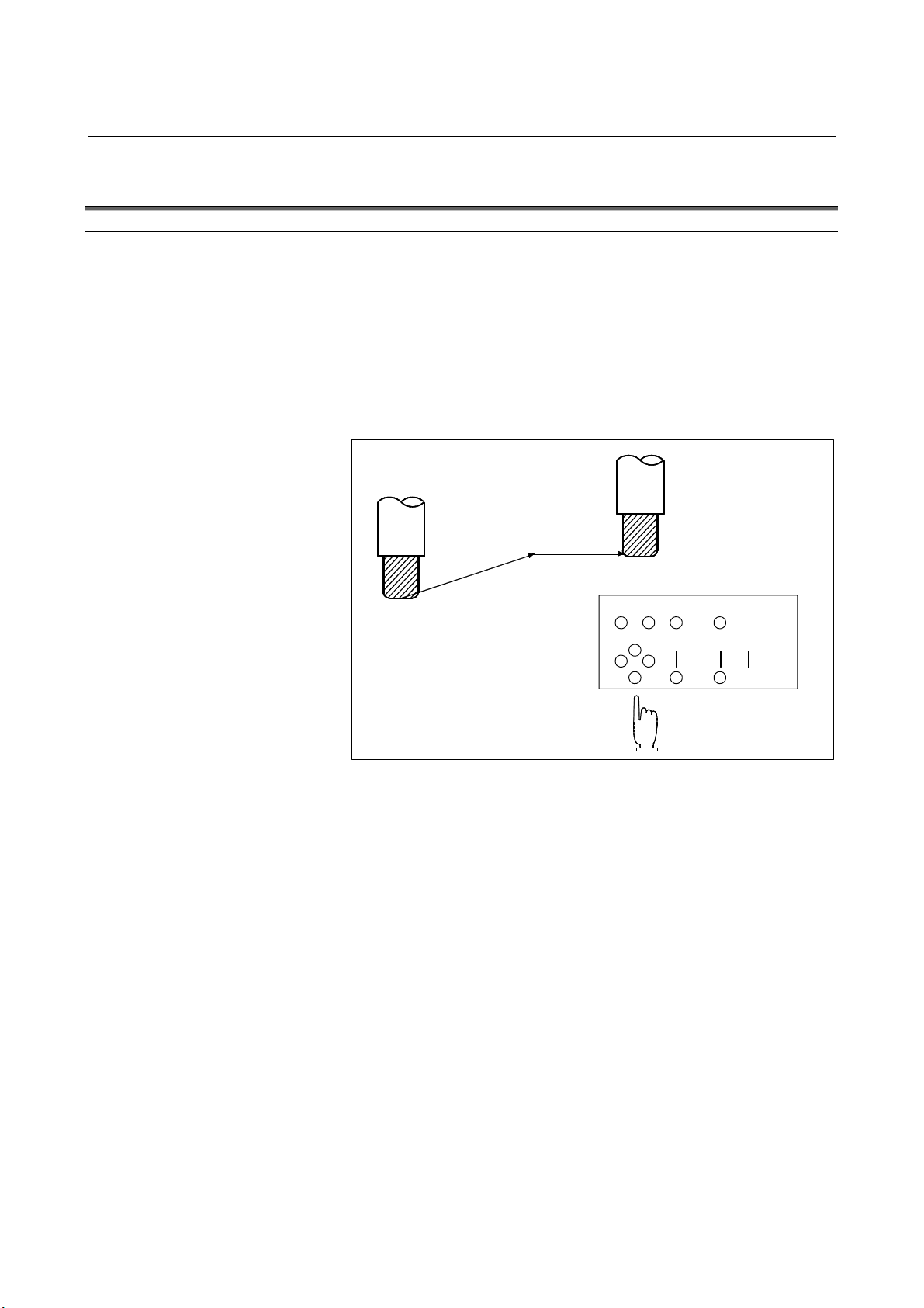
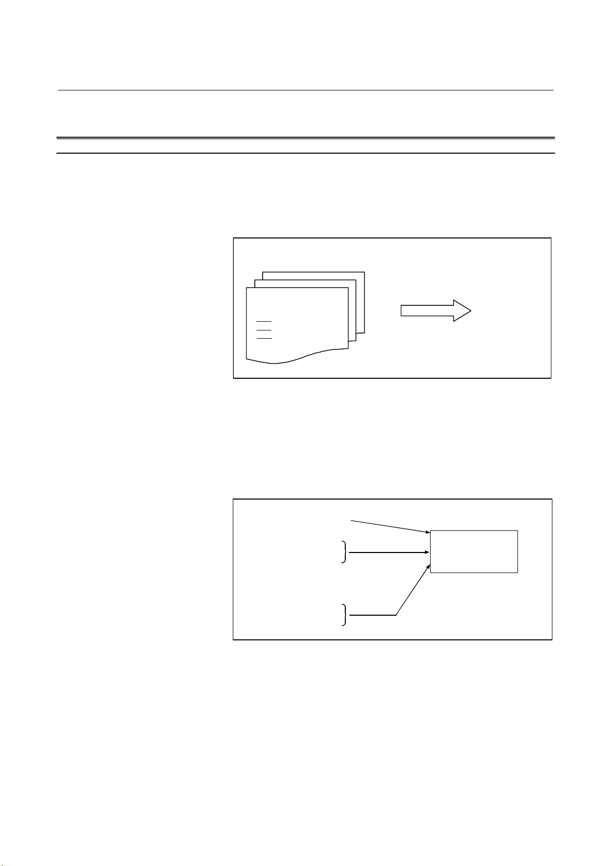
- Program selection
Select the program used for the workpiece. Ordinarily, one program
is prepared for one workpiece. If two or more programs are in memory,
select the program to be used, by searching the program number
(Section III-9.3).
Programs in memory
- Start and stop
O1001
G92
M30
Search for desired program by
file name or program number.
utomatic
operation
Fig. 1.3 (a) Program selection for automatic operation
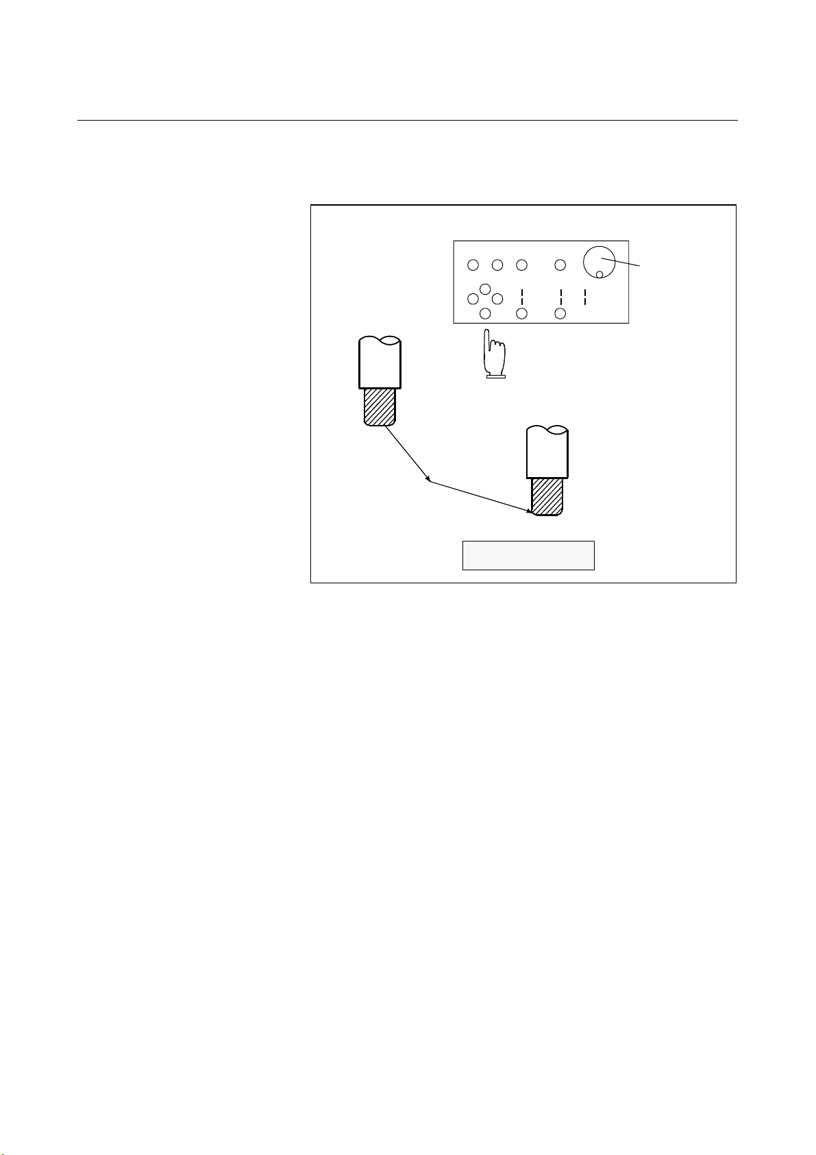
Pressing the cycle start pushbutton causes automatic operation to start.
By pressing the feed hold or reset pushbutton, automatic operation
pauses or stops. By specifying the program stop or program
termination command in the program, the running will stop during
automatic operation. When one process machining is completed,
automatic operation stops. (See Section III-4)
Cycle start
Feed hold
Reset
Stop
Start
utomatic
operation
Stop caused
Program stop
Program end
by program
Fig. 1.3 (b) Start and stop for automatic operation
- 824 -
Page 29
B-63944EN/02 OPERATION 1.GENERAL
p
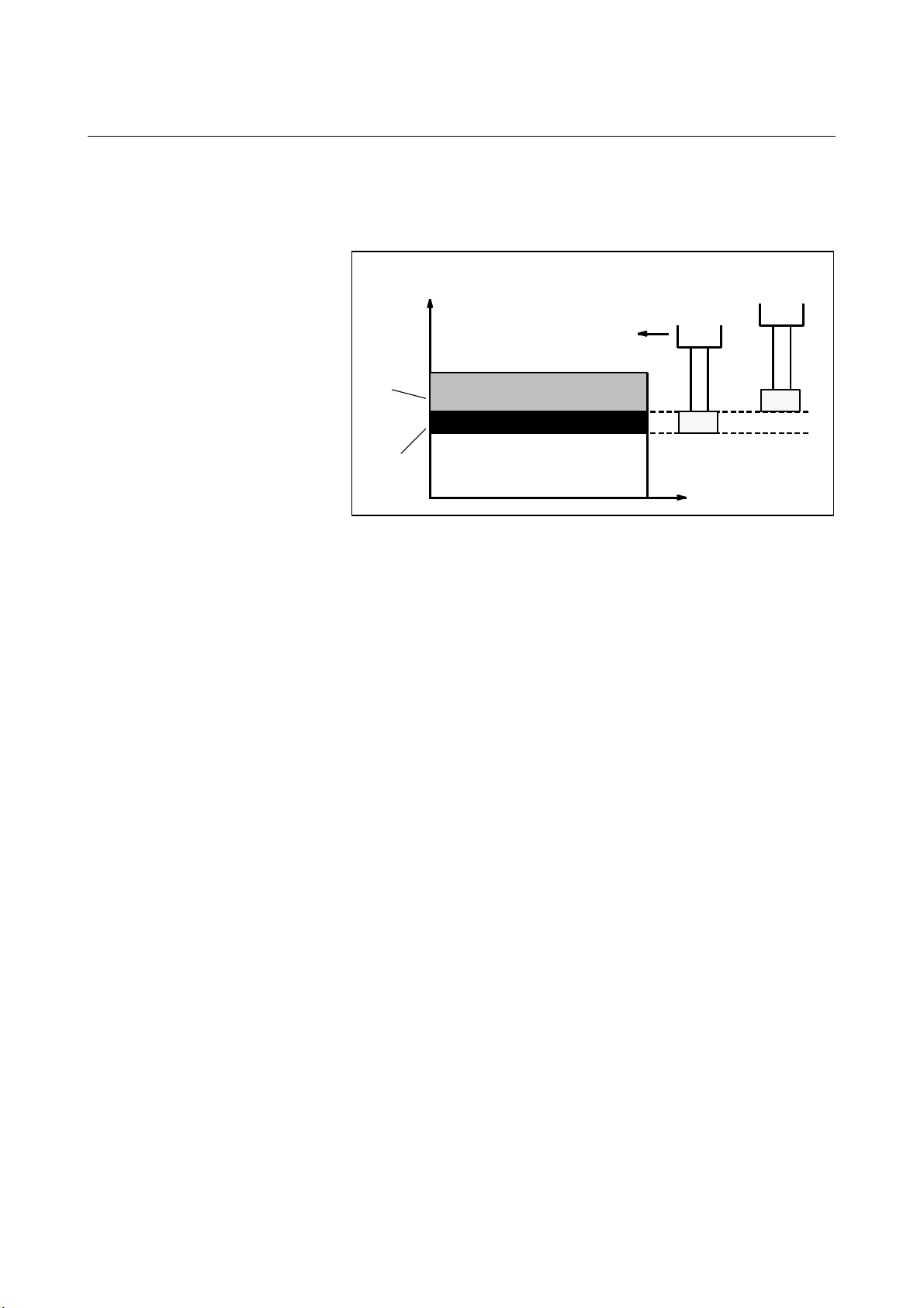
- Handle interruption
While automatic operation is being executed, tool movement can
overlap automatic operation by rotating the manual handle. (See
Section III-4.4)
Tool position
Z
Programmed
depth of cut
Depth of cut
by handle
interruption
Fig. 1.3 (c) Handle interruption for automatic operation
Tool position after
handle interru
during automatic
operation
tion
X
- 825 -
Page 30
1.GENERAL OPERATION B-63944EN/02
1.4 TESTING A PROGRAM
Before machining is started, the automatic running check can be
executed.
It checks whether the created program can operate the machine as
desired.
This check can be accomplished by running the machine actually or
viewing the position display change (without running the machine)
(See Section III-5).
1.4.1 Check by Running the Machine
Explanation
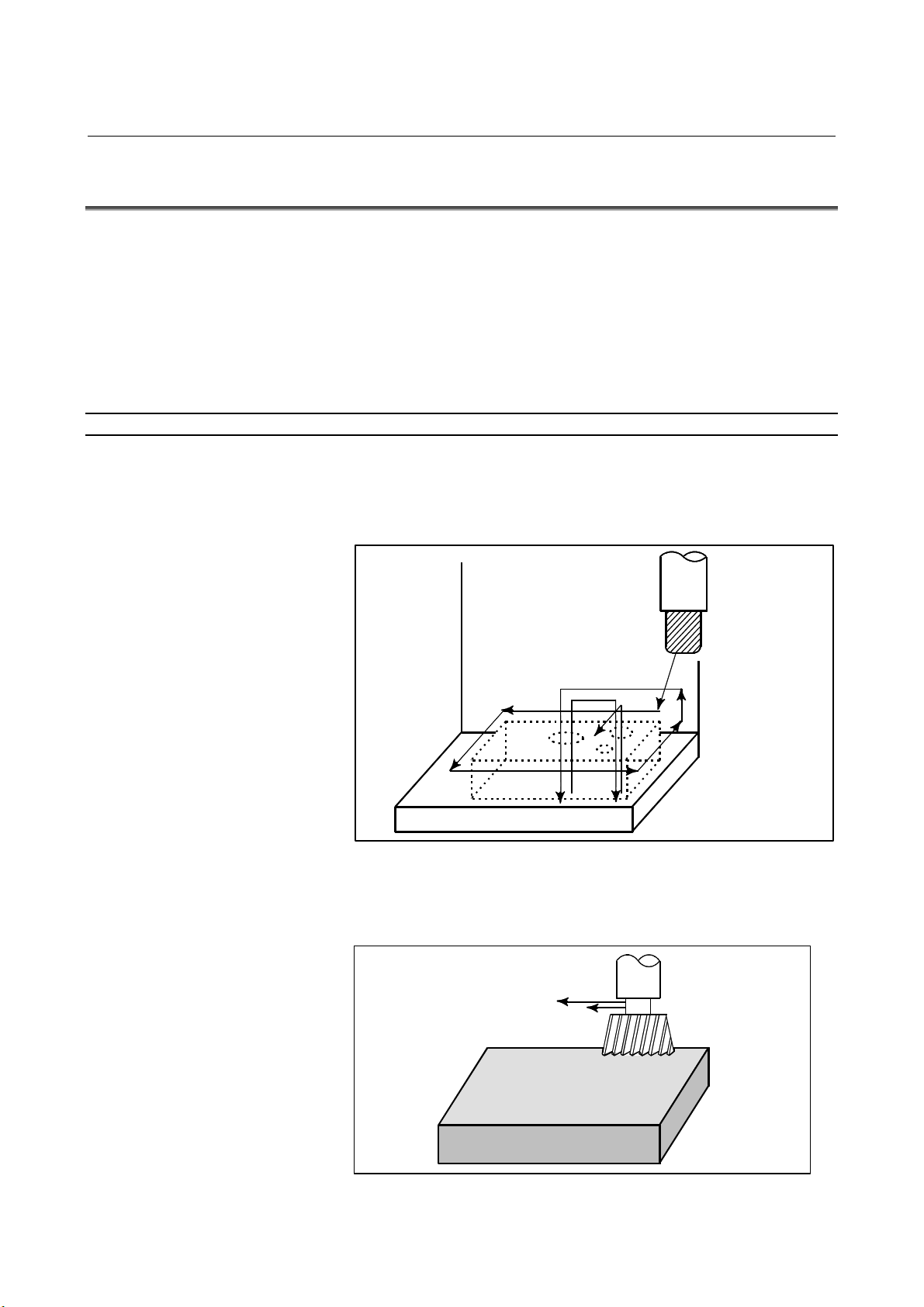
- Dry run
Remove the workpiece, check only movement of the tool. Select the
tool movement rate using the dial on the operator's panel. (See Section
III-5.4)
- Feedrate override
Tool
Table
Fig. 1.4.1 (a) Dry run
Check the program by changing the feedrate specified in the program.
(See Section III-5.2)
Feedrate specified by program :
100 mm/min.
Tool
Feedrate after feed rate
override (20%) : 20 mm/min.
- 826 -
Workpiece
Fig. 1.4.1 (b) Feedrate override
Page 31

B-63944EN/02 OPERATION 1.GENERAL
- Single block
When the cycle start pushbutton is pressed, the tool executes one
operation then stops. By pressing the cycle start again, the tool
executes the next operation then stops. The program is checked in this
manner. (See Section III-5.5)
Cycle
start
Cycle start
Stop
Cycle
start
Workpiece
Fig. 1.4.1 (c) Single Block
Cycle
start
Tool
StopStop
- 827 -
Page 32

1.GENERAL OPERATION B-63944EN/02
1.4.2 How to View the Position Display Change without Running
the Machine
Explanation
- Machine Lock
MDI
X
Tool
Workpiece
The tool remains stopped, and only the
positional displays of the axes change.
Fig. 1.4.2 (a) Machine Lock
- Auxiliary function lock
When automatic running is placed into the auxiliary function lock
mode during the machine lock mode (See Sections III-5.1), all
auxiliary functions (spindle rotation, tool replacement, coolant on/off,
etc.) (See Section III-5.1) are disabled.
Y
Z
- 828 -
Page 33

B-63944EN/02 OPERATION 1.GENERAL
1.5 EDITING A PROGRAM
After a created program is once registered in memory, it can be
corrected or modified from the MDI panel (See Section III-10).
This operation can be executed using the program edit function.
- 829 -
Page 34

1.GENERAL OPERATION B-63944EN/02
1.6 DISPLAYING AND SETTING DATA
The operator can display or change a value stored in CNC internal
memory by key operation on the MDI screen (See III-12).
Data setting
Data display
Screen Keys
MDI
CNC memory
Explanation
- Offset value
Fig. 1.6 (a) Displaying and setting data
Geometry Wear
compensation compensation
CNC memory
Screen Keys
MDI
Setting
Display
Tool compensation number 1 12.3 25.0
Tool compensation number 2 20.0 40.0
Tool compensation numb er 3
Fig. 1.6 (b) Displaying and Setting Offset Values
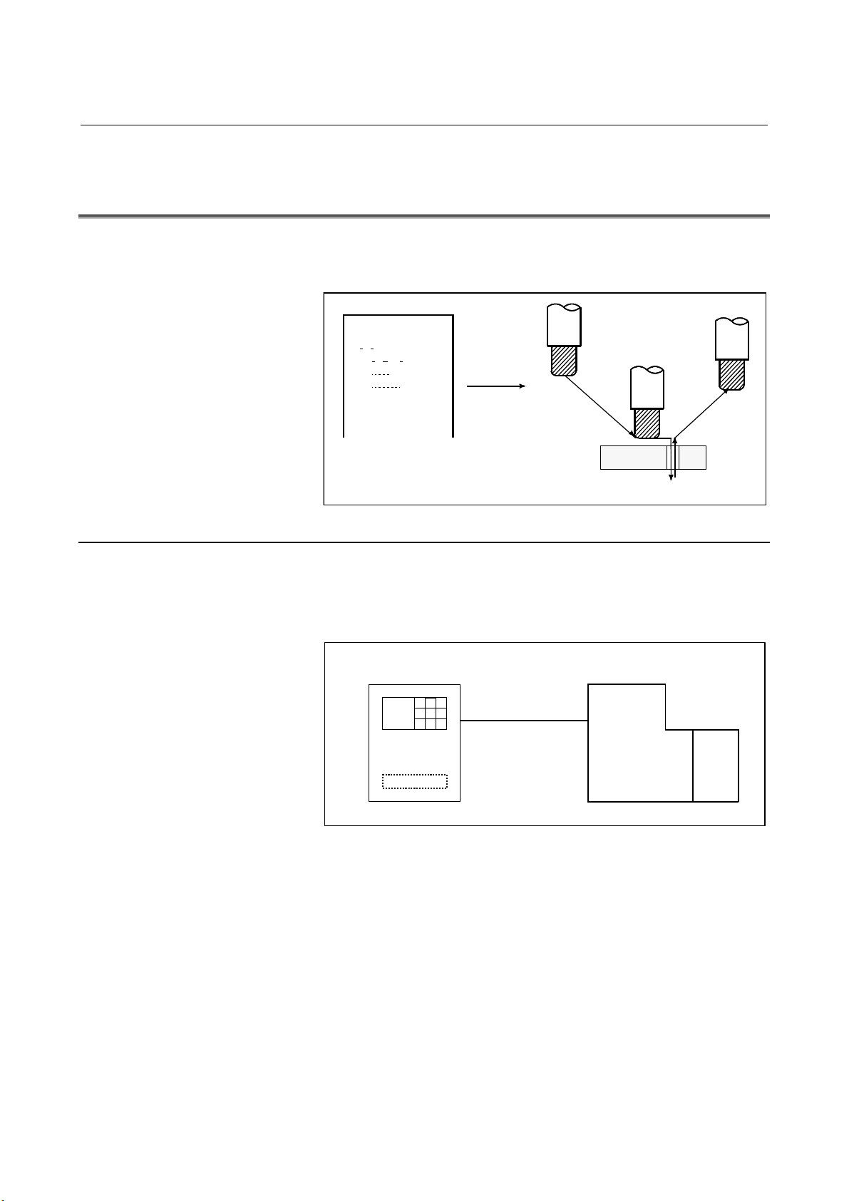
The tool has the tool dimension (length, diameter). When a workpiece
is machined, the tool movement value depends on the tool dimensions.
By setting tool dimension data in CNC memory beforehand,
automatically generates tool routes that permit any tool to cut the
workpiece specified by the program. Tool dimension data is called the
offset value.
- 830 -
Page 35

B-63944EN/02 OPERATION 1.GENERAL
A
1st tool path
Machined
shape
2nd tool path
Offset value of the 1st tool
Offset value of the 2nd tool
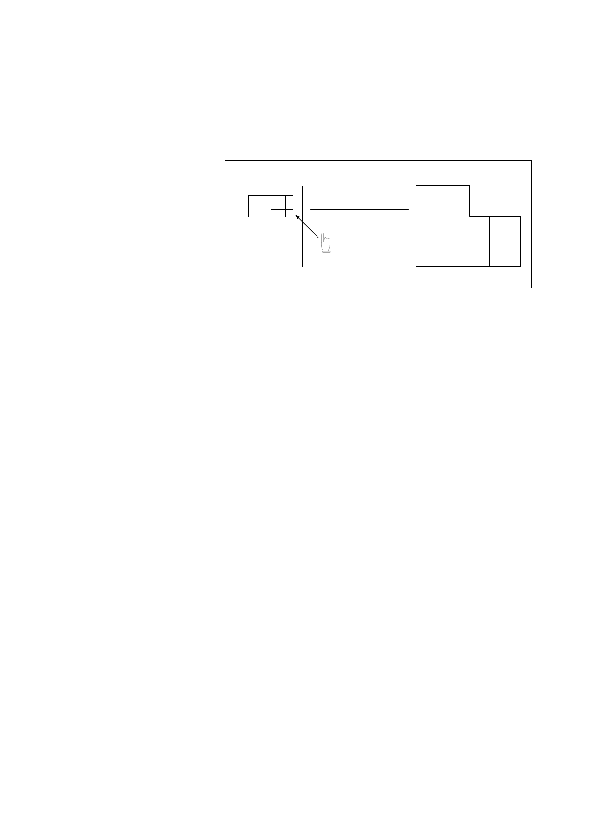
- Displaying and setting operator's setting data
Apart from parameters, there is data that is set by the operator in
operation. This data causes machine characteristics to change.
For example, the following data can be set:
• Inch/Metric switching
• Selection of I/O devices
• Mirror image cutting on/off
The above data is called setting data (See Section III-12.3.1).
Screen
MDI
Keys
Fig. 1.6 (c) Offset value
Setting data
Setting
Displaying
Inch/Metric switching
Selection of I/O device
Mirror image ON/OFF setting
:
:
:
CNC Memory
Operational
characteristics
Program
utomatic
operation
Movement of
the machine
Fig. 1.6 (d) Displaying and setting operator's setting data
- 831 -
Page 36

1.GENERAL OPERATION B-63944EN/02
A
f
p
y
- Displaying and setting parameters
The CNC functions have versatility in order to take action in
characteristics of various machines.
For example, CNC can specify the following:
- Rapid traverse rate of each axis
- Whether increment system is based on metric system or inch
system.
- How to set command multiply/detect multiply (CMR/DMR)
Data to make the above specification is called parameters (See Section
III-12.4.1).
Parameters differ depending on machine tool.
Parameter
Rapid traverse rate
Position control
Reference position return
Backlash compensation data
Pitch error compensation data
:
:
:
Screen Keys
MDI
Setting
Display
- Data protection key
CNC memory
Operational
characteristics
Program
utomatic
operation
Movement o
the machine
Fig. 1.6 (e) Displaying and setting parameters
A key called the data protection key can be defined. It is used to
prevent part programs, offset values, parameters, and setting data from
being registered, modified, or deleted erroneously (See Section
III-12).
Data Setting
Screen Keys
MDI
Data
rotection ke
Registration / modification inhibition
Machine
operator's panel
Program
Offset value
Parameters
Setting data
CNC memory
Fig. 1.6 (f) Data protection key
Data protection key
Signal
- 832 -
Page 37

B-63944EN/02 OPERATION 1.GENERAL
prog
1.7 DISPLAY
1.7.1 Program Display
The contents of the currently active program are displayed. In addition,
the
(See Section III-12.2.1)
Running program number
Contents of
ram
The line currently being executed
is indicated by the cursor.
Running sequence number
Fig. 1.7.1 (a)
A list of the programs held in the currently selected folder is
displayed.
Fig. 1.7.1 (b)
- 833 -
Page 38

1.GENERAL OPERATION B-63944EN/02
1.7.2 Current Position Display
The current position of the tool is displayed with the coordinate
values.
Moreover, the distance from the current position to a target point can
be displayed as a remaining travel distance.
(See Section III-12.1.1, 12.1.2, 12.1.3.)
Y
X
Y
Workpiece coordinate
system
Fig. 1.7.2 (a)
X
- 834 -
Fig. 1.7.2 (b)
Page 39

B-63944EN/02 OPERATION 1.GENERAL
1.7.3 Alarm Display
When a trouble occurs during operation, error code and alarm message
are displayed on the screen. (See Section III-7.1.)
See APPENDIX G for the list of error codes and their meanings.
Fig. 1.7.3 (a)
1.7.4 Parts Count Display, Run Time Display
The position display screen displays a run time, cycle time, and parts
count. (See Section lll-12.3.3.)
Fig. 1.7.4 (a)
- 835 -
Page 40

2.OPERATIONAL DEVICES OPERATION B-63944EN/02
2 OPERATIONAL DEVICES
As operational devices, setting and display devices attached to the
CNC, and machine operator's panels are available.
For machine operator's panels, refer to the relevant manual of the
machine tool builder.
- 836 -
Page 41

B-63944EN/02 OPERATION 2.OPERATIONAL DEVICES
2.1 SETTING AND DEISPLAY UNITS
The setting and display units are shown in Subsections 2.1.1 to 2.1.5
of Part III.
7.2" LCD CNC Display Panel ............................................. III-2.1.1
8.4" LCD CNC Display Panel ............................................. III-2.1.2
10.4" LCD CNC Display Panel ........................................... III-2.1.3
12.1" LCD CNC Display Panel ........................................... III-2.1.4
15" LCD CNC Display Panel .............................................. III-2.1.5
Standard MDI Unit (ONG Key) .......................................... III-2.1.6
Standard MDI Unit (QWERTY Key) .................................. III-2.1.7
Small MDI Unit (ONG Key) ............................................... III-2.1.8
- 837 -
Page 42

2.OPERATIONAL DEVICES OPERATION B-63944EN/02
2.1.1 7.2" LCD CNC Display Panel
2.1.2 8.4" LCD CNC Display Panel
- 838 -
Page 43

B-63944EN/02 OPERATION 2.OPERATIONAL DEVICES
2.1.3 10.4" LCD CNC Display Panel
- 839 -
Page 44

2.OPERATIONAL DEVICES OPERATION B-63944EN/02
2.1.4 12.1" LCD CNC Display Panel
2.1.5 15" LCD CNC Display Panel
- 840 -
Page 45

B-63944EN/02 OPERATION 2.OPERATIONAL DEVICES
A
A
A
A
A
A
2.1.6 Standard MDI Unit (ONG Key)
Unit with machining center system
Uppercase/lowercase
switch key
Shift key
UX key
CTRL key
LT key
TAB key
Reset keyHelp key
ddress/numeric keys
Edit keys
Cancel (CAN) key
Input key
Unit with lathe system
Uppercase/lowercase
switch key
Shift key
UX key
CTRL key
LT key
TAB key
Page change keys
(Page key)
Reset key Help key
Cursor keys Function keys
ddress/numeric keys
Edit keys
Cancel (CAN) key
Input key
Page change keys
(Page key)
Cursor keys Function keys
- 841 -
Page 46

2.OPERATIONAL DEVICES OPERATION B-63944EN/02
A
A
A
2.1.7 Standard MDI Unit (QWERTY Key)
Reset key
ddress keys
Uppercase/lowercase
switch key
UX key
CTRL key
LT key
TAB key
Help key
Page change keys
(Page key)
Cursor keys
Function keys
Edit keys
Numeric keys
Shift key
Input key
Cancel (CAN) key
- 842 -
Page 47

B-63944EN/02 OPERATION 2.OPERATIONAL DEVICES
A
A
2.1.8 Small MDI Unit (ONG Key)
Unit with machining center system
ddress/numeric keys
Cancel (CAN) key
Input key
Function keys
Page change keys
(Page key)
Shift key
Help key
Reset key
Unit with lathe system
Function keys
Page change keys
(Page key)
Edit keys
Cursor keys
ddress/numeric keys
Cancel (CAN) key
Input key
Shift key
Help key
Reset key
Edit keys
Cursor keys
- 843 -
Page 48

2.OPERATIONAL DEVICES OPERATION B-63944EN/02
2.2 OPERATIONAL DEVICES
Table 2.2 (a) Explanation of the MDI keyboard
Number Name Explanation
RESET key
N
RESET
Press this key to reset the CNC, to cancel an alarm, etc.
HELP
Press this button to use the help function when uncertain about the operation
of an MDI key (help function).
The soft keys have various functions, according to the Applications. The soft key
functions are displayed on the display unit.
4
(
. .
Press these keys to input alphabetic, numeric, and other characters.
Some keys have two characters on their keytop. Pressing the <SHIFT> key
SHIFT
switches the characters. Special character # is displayed on the screen when a
character indicated at the bottom right corner on the keytop can be entered.
When an address or a numerical key is pressed, the data is input to the buffer,
and it is displayed on the screen. To copy the data in the key input buffer to the
INPUT
offset register, etc., press the <INPUT> key. This key is equivalent to the
[INPUT] key of the soft keys, and either can be pressed to produce the same
result.
Press this key to delete the last character or symbol input to the key input buffer.
Example) When the key input buffer displays
> N001X100Z_
>N001X100Z_
CAN
and the cancel key
is pressed, Z is canceled and
CAN
>N001X100_
is displayed.
Press these keys when editing the program.
: ALTER
ALTER
: INSERT
DELETE
INSERT
DELETE
: DELETE
1
HELP key
2
3 Soft keys
Address and numeric keys
4
SHIFT key
5
INPUT key
6
CANCEL (CAN) key
7
Edit keys
8
ALTER INSERT
9
10
Function keys
POS
PROG
Cursor keys
. .
Press theses keys to switch display screens for each function.
See lll-2.3 for details of the function keys.
There are four different cursor move keys.
: This key is used to move the cursor to the right or in the forward
direction. The cursor is moved in short units in the forward direction.
: This key is used to move the cursor to the left or in the reverse direction.
The cursor is moved in short units in the reverse direction.
: This key is used to move the cursor in a downward or forward direction.
The cursor is moved in large units in the forward direction.
: This key is used to move the cursor in an upward or reverse direction.
The cursor is moved in large units in the reverse direction.
- 844 -
Page 49

B-63944EN/02 OPERATION 2.OPERATIONAL DEVICES
A
A
A
Table 2.2 (a) Explanation of the MDI keyboard
Number Name Explanation
Page change keys
(Page keys)
11
Uppercase/lowercase
switch key
12
PC function key
PAGE
PAGE
BC
/abc
Two kinds of page change keys are described below.
: This key is used to changeover the page on the screen in the forward
PAGE
direction.
: This key is used to changeover the page on the screen in the reverse
direction.
PAGE
Press this key to switch between uppercase and lowercase when entering
alphabetic characters.
13
CTRL
UX
LT TAB
These keys are used with the personal computer function of the 300i/300is,
310i/310is, 320i/320is.
Explanation
- 15” LCD/MDI soft key configuration
The 15” LCD panel has 12 soft keys horizontally and 9 soft keys
vertically.
As shown below, the 8 vertical soft keys and the lowermost key are
used as chapter selection soft keys. By pressing each of these keys,
the screen (chapter) belonging to each function can be selected. The
horizontal 12 soft keys are used to perform operations on the screen
selected with a vertical soft key.
For an LCD display with a touch panel, touch a soft key on the screen
to select it.
Vertical soft keys
Displays operations on selected chapter.
Horizontal soft keys
In this manual, the descriptions below assume a 10.4" LCD display
panel with 12 soft keys.
- 845 -
Page 50

2.OPERATIONAL DEVICES OPERATION B-63944EN/02
- Key operation with multi-path control
In the multi-path control, be sure to select the tool post for which data
is specified, using the path selection switch on the machine operator's
panel. Then, perform keyboard operation, such as displaying or
specifying various data items, and editing a program.
- 846 -
Page 51

B-63944EN/02 OPERATION 2.OPERATIONAL DEVICES
2.3 FUNCTION KEYS AND SOFT KEYS
The function keys are used to select the type of screen (function) to be
displayed. When a soft key (section select soft key) is pressed
immediately after a function key, the screen (section) corresponding to
the selected function can be selected.
- 847 -
Page 52

2.OPERATIONAL DEVICES OPERATION B-63944EN/02
p
A
2.3.1 General Screen Operations
- Procedure
1 By pressing a function key on the MDI panel, the chapter
selection soft keys that belong to the function are displayed.
Example 1)
Example 2)
Cha
ter selection soft keys
2 When one of the chapter selection soft keys is pressed, the screen
of the chapter is displayed. If the soft key of a desired chapter
is not displayed, press the continuous menu key.
In a chapter, a further choice may be made from multiple
chapters.
3 When the screen of a desired chapter is displayed, press the
operation selection key to display operations to be performed.
4 Select a desired operation with the operation selection soft key.
Depending on the operation to be executed, an auxiliary menu of
soft keys is displayed. Perform an operation according to the
indications on the auxiliary menu.
Operation selection key
Continuous menu key
Example 3)
Operation selection soft keys Return menu key
uxiliary menu
5 To return to the display of chapter selection soft keys, press the
return menu key.
A general screen display procedure is provided above.
The actual display procedure varies from one screen to another.
For details, see each description of operation.
- 848 -
Page 53

B-63944EN/02 OPERATION 2.OPERATIONAL DEVICES
- Button design change depending on soft key state
The soft keys assume one of the following states, depending on the
selection target:
• Chapter selection soft keys
• Operation selection soft keys
• Auxiliary menu of operation selection soft keys
Depending on the state, the button images of the soft keys change.
From the button images, which state the soft keys are assuming can be
known.
Example)
• Chapter selection soft keys
• Operation selection soft keys
• Auxiliary menu of operation selection soft keys
- 849 -
Page 54

2.OPERATIONAL DEVICES OPERATION B-63944EN/02
2.3.2 Function Keys
Function keys are provided to select the type of screen to be displayed.
The following function keys are provided on the MDI panel:
POS
PROG
OFFSET
SETTING
SYSTEM
MESSAGE
GRAPH
CUSTOM1
CUSTOM2
Press this key to display the position screen.
Press this key to display the program screen.
Press this key to display the offset/setting screen.
Press this key to display the system screen.
Press this key to display the message screen.
Press this key to display the graphics screen.
Press this key to display the custom screen (conversational macro
screen).
Unused.
- 850 -
Page 55

B-63944EN/02 OPERATION 2.OPERATIONAL DEVICES
2.3.3 Soft Keys
By pressing a soft key after a function key, the corresponding screen
of the function can be displayed.
The chapter selection soft keys of each function are described below.
The horizontal four keys on the right-hand side are assigned to chapter
selection soft keys. When multiple pages are used for chapter
selection soft keys, [+] is displayed on the continuous menu key
(rightmost soft key). Press the continuous menu key to switch
between chapter selection soft keys.
NOTE
1 Press function keys to switch between screens that
are used frequently.
2 Some soft keys are not displayed depending on the
option configuration.
If position indications are provided on the left half of the screen when
POS
a key other than the function key
is pressed, the left half of the
soft keys is displayed as follows at all times:
- 851 -
Page 56

2.OPERATIONAL DEVICES OPERATION B-63944EN/02
Position display screen
The chapter selection soft keys that belong to the function key
and the function of each screen are described below.
(1) (2) (3) (4) (5)
POS
Page 1
Page 2
ABS REL ALL HNDL
(OPRT)
(6) (7) (8) (9) (10)
MONI 5AXMAN
(OPRT)
Table 2.3.3 (a) Position display screen
No. Chapter menu Description
(1) ABS Selects the absolute coordinate display screen.
(2) REL Selects the relative coordinate display screen.
(3) ALL Selects the overall coordinate display screen.
(4) HNDL Selects the operation screen for manual handle
operation.
(6) MONI Selects the screen for displaying the servo axis load
meter, serial spindle load meter, and speedometer.
(7) 5AXMAN Displays a handle pulse interrupt amount in manual
feed for 5-axis machining.
+
+
- 852 -
Page 57

B-63944EN/02 OPERATION 2.OPERATIONAL DEVICES
Program screen
The chapter selection soft keys that belong to the function key
PROG
and the function of each screen are described below.
(1) (2) (3) (4) (5)
Page 1
Page 2
PROGRA
FOLDER NEXT CHECK (OPRT)
M
(6) (7) (8) (9) (10)
RSTR
JOG
(OPRT)
Table 2.3.3 (b) Program
No. Chapter menu Description
(1) PROGRAM Selects the screen for displaying a list of part
programs currently registered.
(2) FOLDER Selects the screen for displaying a list of part
programs currently registered.
(3) NEXT Selects the screen for displaying the command
values of the block currently executed and the next
block to be executed among the command values.
(4) CHECK Selects the screen for displaying programs, position
data, modal information, and so forth
simultaneously.
(6) RSTR Selects the operation screen for restarting an
interrupted program operation.
(7) JOG Selects the screen for executing, in the JOG mode,
data specified in the program format from the MDI.
+
+
- 853 -
Page 58

2.OPERATIONAL DEVICES OPERATION B-63944EN/02
Offset/setting screen
The chapter selection soft keys that belong to the function key
and the function of each screen are described below.
(1) (2) (3) (4) (5)
OFFSET
SETTING
Page 1
Page 2
Page 3
Page 4
Page 5
OFFSET SETTING
(6) (7) (8) (9) (10)
MACRO
(11) (12) (13) (14) (15)
OFST.2 W. SH F T GEOM.2
(16) (17) (18) (19) (20)
(21) (22) (23) (24) (25)
CHUCK
TAIL
PR-LV
LANG. PROTECT
WORK
OPR
TOOL
MANAGER
GUARD
(OPRT)
(OPRT)
(OPRT)
(OPRT)
(OPRT)
+
+
+
+
+
Page 6
Page 7
(26) (27) (28) (29) (30)
(31) (32) (33) (34) (35)
WORK
SET ER
TOOL
LIFE
- 854 -
(OPRT)
(OPRT)
+
+
Page 59

B-63944EN/02 OPERATION 2.OPERATIONAL DEVICES
Table 2.3.3 (c) Offset
No. Chapter menu Description
(1) OFFSET Selects the screen for setting tool offset values.
(2) SETTING Selects the screen for setting the setting
parameters.
(3) WORK Selects the screen for setting a workpiece
coordinate system offset.
(6) MACRO Selects the screen for setting macro variables.
(8) OPR Selects the screen for operating some operation
switches on the machine operator's panel as soft
switches.
(9) TOOL
MANAGER
(11) OFST.2 Selects the screen for setting a Y-axis offset.
(12) W.SHFT Selects the screen for setting a workpiece
(13) GEOM.2 Selects the screen for setting a second geometry
(17) PR-LV Selects the screen for setting a precision level.
(21) CHUCK TAIL Selects the chuck tail stock barrier screen.
(22) LANG. Selects the screen for setting a display language.
(23) PROTECT Selects the screen for setting data protection.
(24) GUARD Selects the screen for setting wrong operation
(29)
(31)
TOOL LIFE Selects the screen for operations and setting related
WRK ERR
COMP
Selects the screen for setting data related to tool
management.
coordinate system shift value.
offset.
prevention.
to tool life management.
Selects the screen for setting errors related to
workpiece mounting position.
- 855 -
Page 60

2.OPERATIONAL DEVICES OPERATION B-63944EN/02
A
System screen
The chapter selection soft keys that belong to the function key
and the function of each screen are described below.
(1) (2) (3) (4) (5)
SYSTEM
Page 1
Page 2
Page 3
Page 4
Page 5
PARAM DGNOS
(6) (7) (8) (9) (10)
MEMORY PITCH
(11) (12) (13) (14) (15)
PMC
MAINTE
(16) (17) (18) (19) (20)
MCNG
TUNING
(21) (22) (23) (24) (25)
COLOR
PMC
LADDER
ALL IO ALL IO OPEHIS (OPRT)
MAINTE M-INFO
SERVO
GUIDEM
SERVO
PARAM
PMC
CONFIG
SYSTEM (OPRT)
SP.SET (OPRT)
W. DGN S (OPRT)
(OPRT)
+
+
+
+
+
Page 6
Page 7
(26) (27) (28) (29) (30)
FSSB
(31) (32) (33) (34) (35)
EMBEDDED
PORT
PCMCI
LAN
PRMTUN
ETHNET
BOARD
PROFI-B
US MST
(OPRT)
(OPRT)
- 856 -
+
+
Page 61

B-63944EN/02 OPERATION 2.OPERATIONAL DEVICES
(36) (37) (38) (39) (40)
Page 8
Page 9
Page 10
REMOTE
M CODE
(OPRT)
+
DIAG
(41) (42) (43) (44) (45)
PROFI
SLAVE
DEVNET
MASTER
(OPRT)
+
(46) (47) (48) (49) (50)
DUAL
CHECK
R.TIME
MACRO
(OPRT)
+
Table 2.3.3 (d) System
No. Chapter menu Description
(1) PARAM Selects the screen for setting parameters.
(2) DGNOS Selects the screen for displaying CNC state.
(3) SERVO GUIDEM Selects the screen for displaying the servo guide mate.
(4) SYSTEM Selects the screen for displaying the current system
status.
(6) MEMORY Selects the screen for displaying the contents of
memory.
(7) PITCH Selects the screen for setting pith error compensation.
(8) SERVO PARAM Selects the screen for setting the servo-related
parameters.
(9) SP.SET Selects the screen for spindle-related setting.
(11) PMC MAINTE Selects the screen related to PMC maintenance such
as PMC signal state monitoring and tracing, and PMC
parameter display/editing.
(12) PMC LADDER Selects the screen related to ladder display/editing.
(13) PMC CONFIG Displays the screen for displaying/editing data other
than ladders that makes up a sequence program and
for setting the PMC function.
(16) MCNG TUNING Displays the screen for setting the parameter set for
emphasis on speed (LV1) or emphasis on precision
(LV10).
(17) ALL IO Selects the screen for data I/O.
(18) ALL IO Selects the screen for data input to and output from the
memory card.
(19) OPEHIS Selects the screen for displaying the history of
operations performed by the operator and issued
alarms.
(21) COLOR Selects the screen for setting colors to be used on the
screen.
(22) MAINTE Selects the screen for setting maintenance items to be
managed periodically.
(23) M-INFO Selects the screen for displaying information about
maintenance performed.
- 857 -
Page 62

2.OPERATIONAL DEVICES OPERATION B-63944EN/02
No. Chapter menu Description
(24) W.DGNS Selects the screen for displaying data such as servo
positional deviation values, torque values, machine
signals, and so forth as graphs.
(27) FSSB Selects the screen for making settings related to the
high-speed serial servo bus (FSSB: Fanuc Serial Servo
Bus).
(28) PRMTUN Selects the screen for setting parameters necessary for
start-up and tuning.
(31) EMBEDDED
PORT
(32) PCMCIA LAN Selects the screen for making settings related to the
(33) ETHNET BOARD Selects the screen for making settings related to the
(34) PROFI-BUS MST Selects the screen for making settings related to the
(37) M CODE Selects the screen for setting an M code group.
(41) PROFI SLAVE Selects the screen for making settings related to the
(42) DEVNETMASTER Selects the screen for making settings related to the
(46) DUAL CHECK Selects the screen for making settings related to the
(47) R.TIMEMACRO Selects the screen for making settings related to the
Selects the screen for making settings related to the
embedded Ethernet (embedded port).
embedded Ethernet (PCMCIA Ethernet card).
fast Ethernet/fast data server.
profibus master function.
profibus slave function.
DeviceNet master function.
dual check safety function.
real-time custom macro function.
- 858 -
Page 63

B-63944EN/02 OPERATION 2.OPERATIONAL DEVICES
Message screen
The chapter selection soft keys that belong to the function key
MESSAGE
and the function of each screen are described below.
(1) (2) (3) (4) (5)
Page 1
Page 2
ALARM MSG HISTRY MSGHIS (OPRT)
(6) (7) (8) (9) (10)
BUILT-IN
LOG
PCMCIA
LOG
BOARD
LOG
(OPRT)
Table 2.3.3 (e) Message
No. Chapter menu Description
(1) ALARM Selects the alarm message screen.
(2) MSG Selects the operator message screen.
(3) HISTRY Selects the screen for displaying the details of
alarms issued so far.
(4) MSGHIS Selects the external operator message screen.
(6) BUILT-IN LOG Selects the screen for displaying error messages
related to the embedded Ethernet (embedded port).
(7) PCMCIA LOG Selects the screen for displaying error messages
related to the embedded Ethernet (PCMCIA
Ethernet card).
(8) BOARD LOG Selects the screen for displaying error messages
related to the fast Ethernet/fast data server.
+
+
- 859 -
Page 64

2.OPERATIONAL DEVICES OPERATION B-63944EN/02
Graphic screen
The chapter selection soft keys that belong to the function key
and the function of each screen are described below.
(1) (2) (3) (4) (5)
GRAPH
Page 1
PARAM GRAPH (OPRT)
Table 2.3.3 (f) Graphic
No. Chapter menu Description
(1) PARAM Selects the screen for setting graphic parameters.
(2) GRAPH Selects the screen for graphically displaying the tool
path.
+
- 860 -
Page 65

B-63944EN/02 OPERATION 2.OPERATIONAL DEVICES
2.3.4 Key Input and Input Buffer
When an address and a numeric key are pressed, the character
corresponding to that key is input once into the key input buffer. The
contents of the key input buffer is displayed at the bottom of the LCD
screen.
In order to indicate that it is key input data, a ">" symbol is displayed
immediately in front of it. A "_" is displayed at the end of the key
input data indicating the input position of the next character.
Key input buffer display
Fig. 2.3.4 (a) Key input buffer display
- Switching between upper and lower key characters
To input the lower character of the keys that have two characters
inscribed on them, first press the
question.
When the
position changes to "^". Now lowercase characters can be entered
(shift state).
When a character is input in shift status the shift status is canceled.
Furthermore, if the
is canceled.
It is possible to input up to 32 characters at a time in the key input
buffer.
Press the
input buffer.
(Example)
When the key input buffer displays
>N001X100Z_
and the cancel
SHIFT
key is pressed, "_" indicating the next character input
SHIFT
key is pressed in shift status, the shift status
CAN
key to cancel a character or symbol input in the key
CAN
key is pressed, Z is canceled and
SHIFT
key and then the key in
>N001X100_
is displayed.
- 861 -
Page 66

2.OPERATIONAL DEVICES OPERATION B-63944EN/02
A
- Switching between uppercase and lowercase alphabetic characters
When entering alphabetic characters, the user can switch between
uppercase and lowercase.
BC
By pressing the uppercase/lowercase switch key
, the display of
/abc
the key input buffer changes to enable uppercase or lowercase
alphabetic characters to be entered as described below.
Example)
A> A B C _
State enabling uppercase input
a> a b c _
State enabling lowercase input
2.3.5 Warning Messages
After a character or number has been input from the MDI panel, a data
check is executed when
case of incorrect input data or the wrong operation a flashing warning
message will be displayed on the status display line.
Key input buffer display
Warning message display
State display
Soft key display
FORMAT ERROR The format is incorrect.
WRITE PROTECT
DATA IS OUT OF RANGE The input value exceeds the permitted range.
TOO MANY DIGITS
WRONG MODE
EDIT REJECTED
INPUT
key or a soft key is pressed. In the
Fig. 2.3.5 (a) Warning message display
Table 2.3.5 (a) Warning Messages
Warning message Content
Key input is invalid because of data protect
key or the parameter is not write enabled.
The input value exceeds the permitted
number of digits.
Parameter input is not possible in any mode
other than MDI mode.
It is not possible to edit in the current CNC
status.
- 862 -
Page 67

B-63944EN/02 OPERATION 2.OPERATIONAL DEVICES
2.4 EXTERNAL I/O DEVICES
External I/O devices such as a memory card are available.
By using an external I/O device such as a memory card, the following
data can be input or output:
1. Programs
2. Offset data
3. Parameters
4. Custom macro common variables
For how to input or output data and input data from or output it to a
memory card, see III-8.
- Parameter setting
Before an external input/output device can be used, parameters must
be set as follows.
CNC
Mother board
Channel 1
JA56A
Reader/
puncher
I/O CHANNEL=0
or
I/O CHANNEL=1
Channel 2
JA36A
RS-232-CRS-232-C
Reader/
puncher
I/O CHANNEL=2
This CNC has a total of two channels of reader/puncher interfaces. It
also has a memory card interface. The input/output device to be used
is specified by setting the channel (interface) connected to that device
in setting parameter I/O CHANNEL.
The specified data, such as a baud rate and the number of stop bits, of
an input/output device connected to a specific channel must be set in
parameters for that channel in advance. (These settings are not
required for the memory card interface.)
For channel 1, two combinations of parameters to specify the
input/output device data are provided.
The following shows the interrelation between the reader/puncher
interface parameters for the channels.
- 863 -
Page 68

2.OPERATIONAL DEVICES OPERATION B-63944EN/02
I/O CHANNEL
0020
or foreground input
Set channels to be used
for data input/output.
I/O CHANNEL (0 to 5)
=0 : Channel 1
=1 : Channel 1
=2 : Channel 2
=3 : Channel 3
:
:
:
Input/output to and from the memory
card interface, etc. is also possible.
When IO4 is set
0021
Foreground output
0022
Background input
0023
Background input
The channel setting is the same as
No.0020.
Input/output channel number (parameter No.0020)
↓
0101 Stop bit and other data
I/O CHANNEL=0 0102 Number specified for the input/output device
(Channel 1)
I/O CHANNEL=1 0112 Number specified for the input/output device
(Channel 1)
I/O CHANNEL=2 0122 Number specified for the input/output device
(Channel 2)
:
:
:
I/O CHANNEL=5
0103 Baud rate
0111 Stop bit and other data
0113 Baud rate
0121 Stop bit and other data
0123 Baud rate
- 864 -
Page 69

B-63944EN/02 OPERATION 2.OPERATIONAL DEVICES
2.5 POWER ON/OFF
2.5.1 Turning on the Power
Procedure of turning on the power
Procedure
1 Check that the appearance of the CNC machine tool is normal.
(For example, check that front door and rear door are closed.)
2 Turn on the power according to the manual issued by the
machine tool builder.
3 After the power is turned on, check that the position screen is
displayed. An alarm screen is displayed if an alarm occurs upon
power-on.
Fig. 2.5.1 (a) Position screen (for machining center system)
4 Check that the fan motor is rotating.
WARNING
Until the positional or alarm screen is displayed at
the power on, do not touch them. Some keys are
used for the maintenance or special operation
purpose. When they are pressed, unexpected
operation may be caused.
- 865 -
Page 70

2.OPERATIONAL DEVICES OPERATION B-63944EN/02
2.5.2 Power Disconnection
Procedure of power disconnection
Procedure
1 Check that the LED indicating the cycle start is off on the
operator's panel.
2 Check that all movable parts of the CNC machine tool is
stopping.
3 If an external input/output device such as the Handy File is
connected to the CNC, turn off the external input/output device.
4 Continue to press the <POWER OFF> button for about 5
seconds.
5 Refer to the machine tool builder's manual for turning off the
power to the machine.
- 866 -
Page 71

B-63944EN/02 OPERATION 3.MANUAL OPERATION
3 MANUAL OPERATION
MANUAL OPERATION are six kinds as follows :
3.1 MANUAL REFERENCE POSITION RETURN
3.2 JOG FEED (JOG)
3.3 INCREMENTAL FEED
3.4 MANUAL HANDLE FEED
3.5 MANUAL ABSOLUTE ON AND OFF
3.6 RIGID TAPPING BY MANUAL HANDLE
3.7 MANUAL NUMERICAL COMMAND
3.8 MANUAL FEED FOR 5-AXIS MACHINING
3.9 DISTANCE CODED LINEAR SCALE INTERFACE
3.10 LINEAR SCALE WITH DISTANCE-CODED REFERENCE
MARKS (SERIAL)
- 867 -
Page 72

3.MANUAL OPERATION OPERATION B-63944EN/02
X
C
X
3.1 MANUAL REFERENCE POSITION RETURN
The tool is returned to the reference position as follows :
The tool is moved in the direction specified in parameter ZMI (No.
1006#5) for each axis with the reference position return switch on the
machine operator's panel. The tool moves to the deceleration point at
the rapid traverse rate, then moves to the reference position at the FL
speed. The rapid traverse rate and FL speed are specified in
parameters (No. 1424,1421, and 1425).
Four step rapid traverse override is effective during rapid traverse.
When the tool has returned to the reference position, the reference
position return completion LED goes on. The tool generally moves
along only a single axis, but can move along three axes
simultaneously when specified so in parameter JAX (No.1002#0).
Deceleration point
Rapid traverse motion
Rapid traverse rate
(rapid traverse
override is effective)
Fig. 3.1 (a) Manual reference position return
Procedure for manual reference position return
Procedure
1 Press the reference position return switch, one of the mode
selection switches.
2 To decrease the feedrate, press a rapid traverse override switch.
When the tool has returned to the reference position, the
reference position return completion LED goes on.
3 Press the feed axis and direction selection switch corresponding
to the axis and direction for reference position return. Continue
pressing the switch until the tool returns to the reference position.
The tool can be moved along three axes simultaneously when
specified so in an appropriate parameter setting. The tool moves
to the deceleration point at the rapid traverse rate, then moves to
the reference position at the FL speed set in a parameter.
4 Perform the same operations for other axes, if necessary.
The above is an example. Refer to the appropriate manual provided by
the machine tool builder for the actual operations.
ZERO POSITION
Y Z
X2 Y2 Z2
Reference position
Decelerated motion
FL speed
MIRRROR IMAGE
Y Z
PROGRAM
M02/
MANU
STOP
SPINDLE
M30
ABS
ORI
ATC
READY
TAP
NC?MC?
Fig. 3.1 (b)
- 868 -
Page 73

B-63944EN/02 OPERATION 3.MANUAL OPERATION
Explanation
- Automatically setting the coordinate system
Parameter ZPR (No. 1201#0) is used for automatically setting the
coordinate system. When ZPR is set, the coordinate system is
automatically determined when manual reference position return is
performed.
When α, β and γ are set in parameter 1250, the workpiece coordinate
system is determined so that reference point on the tool holder or the
position of the tip of the reference tool is X= α, Y = β, Z = γ when
reference position return is performed. This has the same effect as
specifying the following command for reference position return:
G92Xα
However, when options of the workpiece coordinate system is
selected, it is not able to use.
YβZγ;
Limitation
- Moving the tool again
Once the reference position return completion LED lights at the
completion of reference position return, the tool does not move unless
the reference position return switch is turned off.
- Reference position return completion LED
The reference position return completion LED is extinguished by
either of the following operations:
• Moving from the reference position.
• Entering an emergency stop state.
- The distance to return to reference position
For the distance (Not in the deceleration condition) to return the tool
to the reference position, refer to the manual issued by the machine
tool builder.
- 869 -
Page 74

3.MANUAL OPERATION OPERATION B-63944EN/02
3.2 JOG FEED (JOG)
In the jog mode, pressing a feed axis and direction selection switch on
the
machine operator's panel continuously moves the tool along the
selected axis in the selected direction.
The jog feedrate is specified in a parameter (No.1423).
The jog feedrate can be adjusted with the jog feedrate override dial.
Pressing the rapid traverse switch moves the tool at the rapid traverse
feedrate (No. 1424) regardless of the position of the jog feedrate
override dial. This function is called the manual rapid traverse.
Manual operation is allowed for one axis at a time. 3 axes can be
selected at a time by parameter JAX (No.1002#0).
Z
X
Procedure for JOG feed
Procedure
1 Press the jog switch, one of the mode selection switches.
2 Press the feed axis and direction selection switch corresponding
to the axis and direction the tool is to be moved. While the switch
is pressed, the tool moves at the feedrate specified in a parameter
(No. 1423). The tool stops when the switch is released.
3 The jog feedrate can be adjusted with the jog feedrate override
dial.
4 Pressing the rapid traverse switch while pressing a feed axis and
direction selection switch moves the tool at the rapid traverse rate
while the rapid traverse switch is pressed. Rapid traverse
override by the rapid traverse override switches is effective
during rapid traverse.
The above is an example. Refer to the appropriate manual provided
by the machine tool builder for the actual operations.
Y
While a switch is pressed, the tool
moves in the direction specified by
the switch.
Fig. 3.2 (a) Jog Feed (JOG)
- 870 -
Page 75

B-63944EN/02 OPERATION 3.MANUAL OPERATION
Explanation
- Manual per revolution feed
The manual per revolution feed is enabled for jog feed by setting
parameter JRV (No. 1402 #4).
During the manual per revolution feed, the tool is jogged at the
feedrate that is obtained by multiplying the spindle speed by the feed
amount per revolution, which is calculated by multiplying the jog
feedrate override value by the feed amount per revolution specified
with the parameter (No. 1423).
During manual per revolution feed, the tool is jogged at the following
feedrate:
Feed distance per rotation of the spindle (mm/rev) (specified with
parameter No. 1423) × JOG feedrate override × actual spindle speed
(rev/min).
Limitation
- Acceleration/deceleration for rapid traverse
Feedrate, time constant and method of automatic acceleration/
deceleration for manual rapid traverse are the same as G00 in
programmed command.
- Change of modes
Changing the mode to the jog mode while pressing a feed axis and
direction selection switch does not enable jog feed. To enable jog feed,
enter the jog mode first, then press a feed axis and direction selection
switch.
- Rapid traverse prior to reference position return
If reference position return is not performed after power-on, pushing
rapid traverse button does not actuate the rapid traverse but the
remains at the JOG feedrate. This function can be disabled by setting
parameter RPD (No.1401#01).
- 871 -
Page 76

3.MANUAL OPERATION OPERATION B-63944EN/02
3.3 INCREMENTAL FEED
In the incremental (INC) mode, pressing a feed axis and direction
selection switch on the machine operator's panel moves the tool one
step along the selected axis in the selected direction. The minimum
distance the tool is moved is the least input increment. Each step can
be 10, 100, or 1000 times the least input increment.
With using bit 2 (HNT) of parameter No. 7103, each step can be
additionally 10 times the lest input increment.
The feedrate set in parameter No. 1423 is applied.
By using the manual feedrate override signal, the feedrate can be
increased or decreased.
The tool can also be moved at the rapid traverse rate by using the
manual rapid traverse selection signal, independent of the manual
feedrate override signal.
Z
Tool
Each time a switch is
pressed, the tool moves one
step in the direction
specified by the switch.
X
Procedure for incremental feed
Procedure
1 Press the INC switch, one of the mode selection switches.
2 Select the distance to be moved for each step with the
magnification dial.
3 Press the feed axis and direction selection switch corresponding
to the axis and direction the tool is to be moved. Each time a
switch is pressed, the tool moves one step. The feedrate is the
same as the jog feedrate.
4 Pressing the rapid traverse switch while pressing a feed axis and
direction selection switch moves the tool at the rapid traverse
rate.
Rapid traverse override by the rapid traverse override switch is
effective during rapid traverse.
The above is an example. Refer to the appropriate manual provided by
the machine tool builder for the actual operations.
Y
Fig. 3.3 (a) Incremental feed
- 872 -
Page 77

B-63944EN/02 OPERATION 3.MANUAL OPERATION
Explanation
- Travel distance specified with a diameter
T
The distance the tool travels along the X-axis can be specified with a
diameter.
- 873 -
Page 78

3.MANUAL OPERATION OPERATION B-63944EN/02
3.4 MANUAL HANDLE FEED
In the handle mode, the tool can be minutely moved by rotating the
manual pulse generator on the machine operator's panel. Select the
axis along which the tool is to be moved with the handle feed axis
selection switches.
The minimum distance the tool is moved when the manual pulse
generator is rotated by one graduation is equal to the least input
increment. One of four types of magnifiers selected with MP1 and
MP2 <G019#4 and #5> can be applied. With bit 2 (HNT) of
parameter No. 7103, the minimum distance can be further 10 times
greater.
The number of manual pulse generators depends on the option as
follows:
• Control on 1 manual handle: Up to 1
• Control on 2 or 3 manual handles:
Up to 3 (Up to three manual pulse generators can be moved at a
time.)
Z
X
Fig. 3.4 (b) Manual handle feed
Procedure for manual handle feed
Procedure
1 Press the handle switch, one of the mode selection switches.
2 Select the axis along which the tool is to be moved by pressing a
handle feed axis selection switch.
3 Select the magnification for the distance the tool is to be moved
by pressing a handle feed magnification switch. The minimum
distance the tool is moved when the manual pulse generator is
rotated by one graduation is equal to the least input increment.
4 Move the tool along the selected axis by rotating the handle.
Rotating the handle 360 degrees moves the tool the distance
equivalent to 100 graduations.
The above is an example. Refer to the appropriate manual provided by
the machine tool builder for the actual operations.
Y
Manual pulse generator
- 874 -
Page 79

B-63944EN/02 OPERATION 3.MANUAL OPERATION
Explanation
- Availability of manual pulse generator in Jog mode (JHD)
Parameter JHD (No. 7100#0) enables or disables the manual handle
feed in the JOG mode.
When the parameter JHD(No. 7100#0) is set 1,both manual handle
feed and incremental feed are enabled.
- Manual handle feed in TEACH IN JOG mode (THD)
By setting bit 1 (THD) of parameter No. 7100, manual handle feed in
TEACH IN JOG mode can be enabled or disabled.
- A command to the MPG exceeding rapid traverse rate (HPF)
Parameter No. 7117 enables the following switching:
Set value 0 :
The feedrate is clamped at the rapid traverse rate and generated
pulses exceeding the rapid traverse rate are ignored. (The
distance the tool is moved may not match the graduations on the
manual pulse generator.)
Other than 0 :
The feedrate is clamped to the rapid traverse rate. However,
those handle pulses beyond the rapid traverse rate are not ignored,
but are processed as follows in connection with the manual
handle feed travel distance selection signals:
(No longer rotating the handle does not immediately stop the tool.
The tool is moved by the pulses accumulated in the CNC before
it stops.)
When the magnification selected by manual handle feed travel
distance selection signals is m and parameter No. 7117 is n:
When n < m: The feedrate is clamped to the value of
parameter No. 7117.
When n ≥ m: The feedrate is clamped to an integral multiple
of a selected magnifier. If the mode is
changed, however, a stop may not occur at an
integral-multiple position.
- Upper feedrate limit in manual handle feed
The upper feedrate limit depends on the input signal (maximum
manual handle feedrate switch signal HNDLF) from the PMC as
follows:
• When HNDLF is set to 0, the feedrate is clamped to the manual
rapid traverse rate (parameter No. 1424).
• When HNDLF is set to 1, the feedrate is clamped to the feedrate
set in parameter No. 1434.
- 875 -
Page 80

3.MANUAL OPERATION OPERATION B-63944EN/02
- Movement direction of an axis to the rotation of MPG (HNGX)
Parameter HNGx (No. 7102#0) switches the direction of MPG in
which the tool moves along an axis, corresponding to the direction in
which the handle of the manual pulse generator is rotated.
This parameter is valid only for the following functions:
• Manual handle feed
• Manual handle interruption
Limitation
WARNING
Rotating the handle quickly with a large
magnification such as ×100 moves the tool too fast.
The feedrate is clamped at the rapid traverse
feedrate.
NOTE
Rotate the manual pulse generator at a rate of five
rotations per second or lower. If the manual pulse
generator is rotated at a rate higher than five
rotations per second, the tool may not stop
immediately after the handle is no longer rotated or
the distance the tool moves may not match the
graduations on the manual pulse generator.
- 876 -
Page 81

B-63944EN/02 OPERATION 3.MANUAL OPERATION
3.5 MANUAL ABSOLUTE ON AND OFF
Whether the distance the tool is moved by manual operation is added
to the coordinates can be selected by turning the manual absolute
switch on or off on the machine operator's panel. When the switch is
turned on, the distance the tool is moved by manual operation is added
to the coordinates. When the switch is turned off, the distance the tool
is moved by manual operation is not added to the coordinates.
Y axis
P2
O
Fig. 3.5 (a) Coordinates with the switch ON
P1
The coordinates values change by the
amount of manual operation.
Manual operation
X axis
Y2
Y1
P2
P1
O2
O1
The coordinates do not change.
X2
X1
Fig. 3.5 (b) Coordinates with the switch OFF
- 877 -
Page 82

3.MANUAL OPERATION OPERATION B-63944EN/02
Explanation
The following describes the relation between manual operation and
coordinates when the manual absolute switch is turned on or off, using
a program example.
G01G90 X100.0Y100.0F010 ; <1>
X200.0Y150.0 ; <2>
X300.0Y200.0 ; <3>
The subsequent figures use the following notation:
Movement of the tool when the switch is on
Movement of the tool when the switch is off
The coordinates after manual operation include the distance the tool is
moved by the manual operation. When the switch is off, therefore,
subtract the distance the tool is moved by the manual operation.
- Manual operation after the end of block
Coordinates when block <1> has been executed after manual
operation (X-axis +20.0, Y-axis +100.0) at the end of movement of
block <2>.
Y
(120.0 , 200.0)
Fig. 3.5 (d) Manual operation after the end of block
- Manual operation after a feed hold
Coordinates when the feed hold button is pressed while block <2> is
being executed, manual operation (Y-axis + 75.0) is performed, and
the cycle start button is pressed and released.
Y
Fig. 3.5 (c) Program example
(220.0 , 250.0)
(200.0 , 150.0)
(100.0 , 100.0)
Switch ON
Switch OFF
Manual
operation
X
(300.0 , 275.0)
(200.0 , 225.0)
(150.0 , 200.0)
(150.0 , 125.0)
Feed hold stop point
Fig. 3.5 (e) Manual operation after a feed hold
(200.0 , 150.0)
(300.0 , 200.0)
- 878 -
X
Switch ON
Switch OFF
Manual
operation
Page 83

B-63944EN/02 OPERATION 3.MANUAL OPERATION
- When reset after a manual operation following a feed hold
Coordinates when the feed hold button is pressed while block <2> is
being executed, manual operation (Y-axis +75.0) is performed, the
control unit is reset with the RESET button, and block <2> is read
again
Y
(200.0 , 225.0)
(150.0 , 200.0)
(150.0 , 125.0)
Feed hold stop point
Fig. 3.5 (f) When reset after a manual operation following a feed hold
(200.0 , 150.0)
(300.0 , 275.0)
(300.0 , 200.0)
- When a movement command in the next block is only one axis
When there is only one axis in the following command, only the
commanded axis returns.
Program
N1 G90 G01 X100. Y100. F500 ;
N2 X200.0 ;
N3 Y150.0 ;
Switch ON
Y
(200.0 , 150.0)
(100.0 , 100.0)
X
N2
Switch ON
Switch OFF
Manual
operation
N3
(200.0 , 100.0)
Switch OFF
Manual
operation
Fig. 3.5 (g) When a movement command in the next block is only one
- When the next move block is an incremental
When the following commands are incremental commands, operation
is the same as when the switch is OFF.
N1
X
axis
- 879 -
Page 84

3.MANUAL OPERATION OPERATION B-63944EN/02
- Manual operation during cutter or tool nose radius compensation
• When the switch is OFF
After manual operation is performed with the switch OFF during
cutter or tool nose radius compensation, automatic operation is
restarted then the tool moves parallel to the movement that would
have been performed if manual movement had not been
performed.
The amount of separation equals to the amount that was
performed manually.
Fig. 3.5 (h)
• When the switch is ON during cutter or tool nose radius
compensation
Operation of the machine upon return to automatic operation
after manual intervention with the switch is ON during execution
with an absolute command program in the cutter or tool nose
radius compensation mode will be described. The vector created
from the remaining part of the current block and the beginning of
the next block is shifted in parallel. A new vector is created
based on the next block, the block following the next block and
the amount of manual movement. This also applies when manual
operation is performed during cornering.
• Manual operation performed in other than cornering
Assume that the feed hold was applied at point P
from P
to PB of programmed path PA, PB, and PC and that the
A
tool was manually moved to PH'. The block end point P
to the point P
and VB2 at PB also move to VB1' and VB2'. Vectors VC1 and
V
B1
between the next two blocks PB - PC and PC - PD are
V
C2
discarded and new vectors V
' by the amount of manual movement, and vectors
B
' and VC2' (VC2' = VC2 in this
C1
example) are produced from the relation between P
. However, since VB2' is not a newly calculated vector,
- P
D
correct offset is not performed at block P
correctly performed after P
.
C
while moving
H
moves
B
' - PC and PC
B
' - PC. Offset is
B
- 880 -
Page 85

B-63944EN/02 OPERATION 3.MANUAL OPERATION
Fig. 3.5 (i)
• Manual operation during cornering
This is an example when manual operation is performed during
cornering. V
, VB1 and VB2 by the amount of manual movement. The new
V
A2
vectors are calculated from V
', VB1', and VB2' are vectors moved in parallel with
A2
and VC2. Then correct cutter or
C1
tool nose radius compensation is performed for the blocks
following P
.
C
Fig. 3.5 (j)
• Manual operation after single block stop
Manual operation was performed when execution of a block was
terminated by single block stop.
Vectors V
and VB2 are shifted by the amount of manual
B1
operation. Sub-sequent processing is the same as case a described
above. An MDI operation can also be intervened as well as
manual operation. The movement is the same as that by manual
operation.
- 881 -
Page 86

3.MANUAL OPERATION OPERATION B-63944EN/02
Fig. 3.5 (k)
- 882 -
Page 87

B-63944EN/02 OPERATION 3.MANUAL OPERATION
3.6 RIGID TAPPING BY MANUAL HANDLE
For execution of rigid tapping, set rigid mode, then switch to handle
mode and move the tapping axis with a manual handle. For rigid
tapping, refer to Section 4.4 in Part II of the User's Manual (T series)
or Section 5.2 in Part II of the User's Manual (M series) and the
relevant manual of the machine tool builder.
Rigid tapping by manual handle
Procedure
1 Stop the spindle and servo axes, then set MDI mode by pressing
the MDI switch among the mode selection switches.
2 Enter and execute the following program:
Example 1) M series / T series (G code systems B, C)
M29 S100 ;
G91 G84 Z0 F1000 ;
Example 2) T series (G code system A)
M29 S100 ;
G84 W0 F1000 ;
The program above is required to determine a screw lead and set
rigid tapping mode. In this program, a tapping axis must always
be specified. Specify a value that does not operate the tapping
axis. With the M series, specify G84 (G74). With the T series,
specify G84 (G88).
WARNING
In this MDI programming, never specify commands
to position the tool at a drilling position and at point
R. Otherwise, the tool moves along an axis.
3 When the entered program is executed, rigid tapping mode is set.
4 After rigid mode is set upon completion of MDI program
execution, switch to the handle mode by pressing the handle
switch among the mode selection switches.
CAUTION
At this time, never press the reset key. Otherwise,
rigid mode is canceled.
5 To perform rigid tapping, select a tapping axis with the handle
feed axis select switch, and move the tapping axis with the
manual handle.
- 883 -
Page 88

3.MANUAL OPERATION OPERATION B-63944EN/02
Explanation
- Manual rigid tapping
Manual rigid tapping is enabled by parameter HRG (No. 5203#0) to 1.
- Cancellation of rigid mode
To cancel rigid mode, specify G80 as same the normal rigid tapping.
When the reset key is pressed, rigid mode is canceled, but the canned
cycle is not canceled.
When the rigid mode switch is to be set to off for rigid mode
cancellation (when parameter CRG (No. 5200#2) is set to 0), the G80
command ends after the rigid mode switch is set to off.
- Spindle rotation direction
The rotation direction of the spindle is determined by a specified
tapping cycle G code and the setting of parameter HRM (No. 5203#1).
For example, when the HRM parameter is set to 0 in G84 mode, the
spindle makes forward rotations as the tapping axis moves in the
minus direction. (When the tapping axis moves in the plus direction,
the spindle makes reverse rotations.)
- Arbitrary tapping axis
With the M series, an arbitrary tapping axis can be selected by setting
bit 0 (FXY) of parameter No. 5101 to 1. With the T series, an
arbitrary tapping axis can be selected not by using bit 0 (FXY) of
parameter No. 5101 (but by using bit 0 (FXY) of parameter No. 5101
when the FS15 format is specified). In this case, specify a G code
for plane selection and the address of the tapping axis when setting the
rigid tapping mode in the MDI mode.
- G84 command/same block specifying both M29 and G84
As the MDI program command for setting the rigid mode, G84 can be
specified as a rigid tapping G code (by setting bit 0 (G84) of
parameter No. 5200 to 1), or M29 and G84 can be specified in the
same block.
Example 1: G91 G84 Z0 F1000 S100 ;
Example 2: G91 G84 Z0 F1000 M29 S100 ;
- Specification of manual handle feed faster than the rapid traverse rate
Set parameter (No.7117) to 0 so that when manual handle feed is
specified which is faster than the rapid traverse rate, the handle pulses
beyond the rapid traverse rate are ignored.
- Series 15 format command
By setting bit 1 (FCV) of parameter No. 0001 to 1, the Series15
format can be used for specification.
Example 1: G91 G84.2(G84.3) Z0 F1000 S100; (M series)
Example 2: G84.2 W0 F1000 S100; (T series : G code systems B, C)
Example 3: G91 G84.2 Z0 F1000 S100; (T series : G code system A)
- 884 -
Page 89

B-63944EN/02 OPERATION 3.MANUAL OPERATION
- Acceleration/deceleration type
When manual rigid tapping is executed, the acceleration/deceleration
type and acceleration/deceleration time constant set in the rigid
tapping parameters are valid.
The same settings are valid also for extraction.
- In the case of multi-spindle operation
In the case of multi-spindle operation, a spindle can be selected by
specifying a P command as well as an S command.
Example : When the 2nd spindle is selected:
M29 S100 P2;
G91 G84 Z0 F1000 ;
Limitation
- Excessive error check
In manual rigid tapping, only an excessive error during movement is
checked.
- Tool axis direction handle feed
Tool axis direction handle feed is disabled.
- Extraction override
In manual rigid tapping, the extraction override function is disabled,
and the use of an acceleration/deceleration time constant for extraction
is disabled.
- Number of repeats
In MDI programming, never specify K0 and L0, which are used to
specify that the number of repeats is 0 and to disable the execution of
a G84 block. If K0 or L0 is specified, rigid mode cannot be set.
- Positioning of the tool to a drilling position
When positioning the tool to a drilling position, select the X-axis or
Y-axis with the axis select switch in handle mode. Never use the
method of positioning to a drilling position in MDI mode or MEM
mode. The method can operate the tapping axis.
- Three-dimensional rigid tapping
Three-dimensional rigid tapping cannot be used in rigid tapping using
the manual handle.
- Interpolation type rigid tapping
Interpolation type rigid tapping cannot be used in rigid tapping using
the manual handle. To perform rigid tapping using the manual
handle, select the conventional type of rigid tapping with bit 3 (CHR)
of parameter No. 5202.
- 885 -
Page 90

3.MANUAL OPERATION OPERATION B-63944EN/02
3.7 MANUAL NUMERICAL COMMAND
The manual numerical command function allows data programmed
through the MDI to be executed in jog mode. Whenever the system
is ready for jog feed, a manual numerical command can be executed.
The following eight functions are supported:
(1) Positioning (G00)
(2) Linear interpolation (G01)
(3) Automatic reference position return (G28)
(4) 2nd/3rd/4th reference position return (G30)
(5) M codes (miscellaneous functions)
(6) S codes (spindle speed functions)
(7) T codes (tool functions)
(8) B codes (second auxiliary functions)
By setting the following parameters, the commands for axial motion
and the M, S, T, and B functions can be disabled:
(1) Positioning (G00): .........................Parameter JAXx (No. 7010#0)
(2) Linear interpolation (G01):............Parameter JAXx (No. 7010#0)
(3) Automatic reference position return (G28):
....................................... Parameter JAXx (No. 7010#0)
(4) 2nd/3rd/4th reference position return (G30):
....................................... Parameter JAXx (No. 7010#0)
(5) M codes (miscellaneous functions): Parameter JMF (No. 7002#0)
(6) S codes (spindle speed functions):.... Parameter JSF (No. 7002#1)
(7) T codes (tool functions):................... Parameter JSF (No. 7002#2)
(8) B codes (second auxiliary functions):Parameter JBF (No. 7002#3)
Procedure Manual numerical command
Procedure
1 Press the jog switch (one of the mode selection switches).
2 Press function key
3 Press soft key [JOG] on the screen. The following manual
numerical command screen is displayed.
PROG
.
- 886 -
Page 91

B-63944EN/02 OPERATION 3.MANUAL OPERATION
Fig. 3.7 (a) Manual numerical command screen
The remaining portion of the axis information currently not
shown on the screen can be displayed by pressing the
PAGE
PAGE
or
key.
NOTE
1 The actual feedrate (F) and the actual spindle speed
(S) are displayed only for 9” window.
2 If two or more identical axis names exist for the
same path, they are not displayed.
- 887 -
Page 92

3.MANUAL OPERATION OPERATION B-63944EN/02
4 Enter the required commands by using address keys and numeric
keys on the MDI panel, then press soft key [INPUT] or the
INPUT
key to set the entered data.
Fig. 3.7 (b)
The following data can be set:
1. G00: ................ Positioning
2. G01: ................ Linear interpolation
3. G28: ................ Automatic reference position return
4. G30: ................ 2nd/3rd/4th reference position return
5. M codes: ......... Miscellaneous functions
6. S codes:........... Spindle speed functions
7. T codes:........... Tool functions
8. B codes: ..........Second auxiliary functions
The set data is maintained even when the screen or mode is changed.
NOTE
When an alarm state exists, data cannot be set.
5 Press the cycle start switch on the machine operator's panel to
start command execution. The status is indicated as "MSTR."
The automatic operation signal, STL, can be turned on by setting
parameter JST (No.7001#2).
NOTE
If the cycle start switch is pressed while an alarm
state exists, a "START REJECTED (ALARM
EXISTED)" warning is generated, and the entered
data cannot be executed.
- 888 -
Page 93

B-63944EN/02 OPERATION 3.MANUAL OPERATION
6 Upon the completion of execution, the "MSTR" status indication
is cleared from the screen, and automatic operation signal STL is
turned off. The set data is cleared entirely. G codes are set to G00
or G01 according to the setting of parameter G01 (No.3402#0).
Explanation
- Positioning
An amount of travel is given as a numeric value, preceded by an
address such as X, Y, or Z. This is always regarded as being an
incremental command, regardless of whether G90 or G91 is specified.
Manual rapid traverse selection switch
Off On
Feedrate
(parameter)
Automatic
acceleration/
deceleration
(parameter)
Override Manual feed override Rapid traverse override
Jog feedrate for each axis
(No.1423)
Exponential acceleration/
deceleration in jog feed for each axis
(No.1624)
Rapid traverse rate for each axis
(No.1420)
Linear acceleration/deceleration
in rapid traverse for each axis
(No.1620)
NOTE
1 When the manual rapid traverse switch is off, the
feedrate is clamped so that the axis-by-axis manual
rapid traverse rate (parameter No. 1424) is not
exceeded.
2 The tool cannot move if linear interpolation type
positioning (where the tool path is linear) has been
performed by setting parameter LRP (No. 1401 #1).
- Linear interpolation (G01)
An amount of travel is given as a numeric value, preceded by an
address such as X, Y, or Z. This is always regarded as being an
incremental command, regardless of whether G90 or G91 is specified.
Axial movements are always performed in incremental mode even
during scaling or polar coordinate interpolation. In addition,
movement is always performed in feed per minute mode regardless of
the specification of G94 or G95.
Feedrate
(parameter)
Automatic acceleration/deceleration
(parameter)
Override Manual feed override
Exponential acceleration/deceleration
Dry run feedrate
(No. 1410)
in cutting feed for each axis
(No.1622)
- 889 -
Page 94

3.MANUAL OPERATION OPERATION B-63944EN/02
NOTE
Since the feedrate is always set to the dry run
feedrate, regardless of the setting of the dry run
switch, the feedrate cannot be specified using F.
The feedrate is clamped such that the maximum
cutting feedrate, set in parameter No. 1430, is not
exceeded.
- Automatic reference position return (G28)
The tool returns directly to the reference position without passing
through any intermediate points, regardless of the specified amount of
travel. For axes for which no move command is specified, however, a
return operation is not performed.
Feedrate
(parameter)
Automatic acceleration/deceleration
(parameter)
Override Rapid traverse override
Linear acceleration/deceleration in
Rapid traverse rate
(No. 1420)
rapid traverse for each axis
(No. 1620)
- 2nd, 3rd, or 4th reference position return (G30)
The tool returns directly to the 2nd, 3rd, or 4th reference position
without passing through any intermediate points, regardless of the
specified amount of travel. To select a reference position, specify 2, 3,
or 4 in address P. If address P is omitted, a return to the second
reference position is performed.
Feedrate
(parameter)
Automatic acceleration/deceleration
(parameter)
Override Rapid traverse override
Linear acceleration/deceleration in
Rapid traverse rate
(No. 1420)
rapid traverse for each axis
(No. 1620)
NOTE
The function for 3rd/4th reference position return is
optional.
1 When the option is not selected
If "P2" is not specified in address P, the alarm
PS0046 is generated and the function cannot be
executed.
2 When the option is selected
If "P2," "P3," or "P4" is not specified in address P,
the alarm PS0046 is generated and the function
cannot be executed.
- 890 -
Page 95

B-63944EN/02 OPERATION 3.MANUAL OPERATION
- M codes (Auxiliary functions)
After address M, specify a numeric value of no more than the number
of digits specified by parameter No. 3030. When M98 or M99 is
specified, it is executed but not output to the PMC.
NOTE
Neither subprogram calls nor custom macro calls
can be performed using M codes.
- S codes (spindle speed functions)
After address S, specify a numeric value of no more than the number
of digits specified by parameter No. 3031.
NOTE
Subprogram calls cannot be performed using S
codes.
- T codes (tool functions)
After address T, specify a numeric value of no more than the number
of digits specified by parameter No. 3032.
NOTE
Subprogram calls cannot be performed using T
codes.
- B codes (second auxiliary functions)
After address B, specify a numeric value of no more than the number
of digits specified by parameter No. 3033.
NOTE
1 B codes can be renamed "U," "V," "W," "A," or "C"
by setting parameter No. 3460. If the new name is
the same as an axis name address, "B" is used.
Note that "U," "V," and "W" can be used for the T
codes only when the G codes are B or C.
2 Subprogram calls cannot be performed using B
codes.
- Data input
(1) When addresses and numeric values of a command are typed,
then soft key [INPUT] is pressed, the entered data is set. In this
case, the input unit is either the least input increment or
calculator-type input format, according to the setting of bit 0
(DPI) of parameter No. 3401.
INPUT
The
[INPUT].
(2) Commands can be typed successively.
key on the MDI panel can be used instead of soft key
- 891 -
Page 96

3.MANUAL OPERATION OPERATION B-63944EN/02
(3) Key entry is disabled during execution.
- Erasing data
If soft key [INPUT] or the
INPUT
key on the MDI panel is
pressed during execution, an "EXECUTION/MODE
SWITCHING IN PROGRESS" warning is output.
(4) If input data contains an error, the following warnings may
appear:
Warning Description
- A G code other than G00, G01, and G28 has been
entered.
- An address other than those displayed on the manual
numerical command screen has been entered.
FORMAT
ERROR
A value that exceeds the following limitations has been
entered.
- Address G: ......... 2 digits
- Address P:.......... 1 digit
- Axis address:...... 9 digits
- M, S, T, B: .......... The parameter-set number of digits
NOTE
Even when the memory protection key is set, key
input can nevertheless be performed.
(1) When soft key [CLEAR] is pressed, followed by soft key
[EXEC], all the set data is cleared. In this case, however, the G
codes are set to G00 or G01, depending on the setting of bit 0
(G01) of parameter No. 3402.
RESET
Data can also be cleared by pressing the
key on the MDI
- Scrolling pages
- Halting execution
panel.
(2) If soft key [CLEAR] is pressed during execution, an
"EXECUTION/MODE SWITCHING IN PROGRESS" warning
is output.
If the whole axis information cannot be displayed on a single page,
you can scroll pages by pressing the
PAGE
or
PAGE
key.
If one of the following occurs during execution, execution is halted,
and the data is cleared in the same way as when soft key [CLEAR] is
pressed. The remaining distance to be traveled is canceled.
(1) When a feed hold is applied
(2) When the mode is changed to other than jog feed mode
(3) When an alarm is generated
(4) When a reset or emergency stop is applied
The M, S, T, and B functions remain effective even upon the
occurrence of the above events, with the exception of (4).
- 892 -
Page 97

B-63944EN/02 OPERATION 3.MANUAL OPERATION
- Modal information
Modal G codes and addresses used in automatic operation or MDI
operation are not affected by the execution of commands specified
using the manual numerical command function.
- Jog feed
When the tool is moved along an axis using a feed axis and direction
selection switch on the manual numerical command screen, the
remaining amount of travel is always shown as "0".
- Disabling the M, S, T, and B functions
By setting bit 0 to bit 3 (JMF, JSF, JTF, and JBF) of parameter No.
7002, the M, S, T, and B functions can be disabled. If a disabled
function is specified, the warning "THIS COMMAND CANNOT BE
EXECUTED." is issued.
Limitation
- M, S, T, and B functions
While automatic operation is halted, manual numerical commands can
be executed. In the following cases, however, a "START REJECTED
(ALREADY EXECUTING)" warning is output, and command
execution is disabled.
(1) When an M, S, T, or B function is already being executed, a
manual numerical command containing an M, S, T, or B function
cannot be executed.
(2) When an M, S, T, or B function is already being executed, and
that function alone is specified or a block specifying that
function also contains another function (such as a move
command or dwell function) which has already been completed,
a manual numerical command cannot be executed.
- Jog feed
When a manual numerical command is specified while the tool is
being moved along an axis by using a feed axis and direction selection
switch, the axial movement is interrupted, and the manual numerical
command is executed. Therefore, the tool cannot be moved along an
axis by using a feed axis and direction selection switch during
execution of a manual numerical command.
- Mirror image
A mirror image cannot be produced for the direction of a specified
axial movement.
- REF mode
The manual numerical command screen is not displayed in the REF
mode.
- 893 -
Page 98

3.MANUAL OPERATION OPERATION B-63944EN/02
- Indexing of the index table and chopping
Commands cannot be specified for an axis along which operation is
being performed during indexing or chopping.
If such an axis is specified for execution, a "THIS COMMAND CAN
NOT EXECUTE" warning is output.
- Functions that cannot be specified
Commands cannot be specified for axes that operate using any of the
following functions.
• Index table indexing
• Chopping
• Spindle positioning
• Polygon turning
• Axis recomposition and superposition control
If the commands are executed for any such axis, a "THIS
COMMAND CAN NOT EXECUTE" warning is generated.
- Functions that cannot be used
Commands cannot be specified for the following functions.
• Extended axis name
• Extended spindle name
• Address P command for multi spindle
• Cs contour control function
- 894 -
Page 99

B-63944EN/02 OPERATION 3.MANUAL OPERATION
3.8 MANUAL FEED FOR 5-AXIS MACHINING
This function enables the use of the following functions.
• Manual feed for 5-axis machining
- Tool axis direction handle feed/tool axis direction JOG
feed/tool axis direction incremental feed
- Tool axis right-angle direction handle feed/tool axis
right-angle direction JOG feed/tool axis right-angle
direction incremental feed
- Tool tip center rotation handle feed/tool tip center rotation
JOG feed/tool tip center rotation incremental feed
- Table vertical direction handle feed/table vertical direction
JOG feed/table vertical direction incremental feed
- Table horizontal direction handle feed/table horizontal
direction JOG feed/table horizontal direction incremental
feed
A handle interrupt can be generated for each handle feed.
Handle interrupts work according to the corresponding handle
feed specifications described hereinafter unless otherwise noted.
• Screen display functions
- Display of the coordinate of the tool tip
- Display of pulse values
- Display of the amount of machine axes movement
NOTE
1 To execute 5-axis machining handle feed requires
the manual handle feed option. Also, to generate
5-axis machining handle interrupts requires the
manual handle interrupt option.
2 A 5-axis machining handle interrupt must not be
generated when a rotation axis command is being
executed during automatic operation.
3 Manual feed for 5-axis machining is disabled when
the manual reference position return mode is
selected.
- 895 -
Page 100

3.MANUAL OPERATION OPERATION B-63944EN/02
3.8.1 Tool Axis Direction Handle Feed/Tool Axis Direction JOG
Feed/Tool Axis Direction Incremental Feed
Overview
In the tool axis direction handle feed, tool axis direction JOG feed,
and tool axis direction incremental feed, the tool or table is moved in
the tool axis direction.
Explanation
- Tool axis direction
The tool axis direction that is taken when all the rotation axes for
controlling the tool are at an angle of 0 degree is specified in
parameters No.19697, No.19698, and No.19699. As the rotation
axes for controlling the tool rotate, the tool axis direction changes
according to the rotation axis angle.
B
C
Tool axis direction
Workpiece
- Tool axis direction feed in the tilted working plane command mode
If bit 0 (TWD) of parameter No. 12320 is set to 1, the feed direction of
the tool axis direction feed in the tilted working plane command mode
is assumed to be the Z direction in the feature coordinate system of the
tilted working plane command.
- Tool axis direction handle feed
The tool axis direction handle feed is enabled when the following four
conditions are satisfied:
<1> Handle mode is selected.
<2> The tool axis direction feed mode signal (ALNGH) is set to "1"
and the table base signal (TB_BASE) is set to "0".
<3> The state of the first manual handle feed axis selection signals
(HS1A - HS1E) to make the tool axis direction handle feed
mode effective is set in parameter No.12310.
<4> The value of parameter No.12310 matches the first manual
handle feed axis selection signals (HS1A - HS1E).
Z
C
B
Y
X
- 896 -
 Loading...