

Page 1
FANUC
3000C
1.
2.
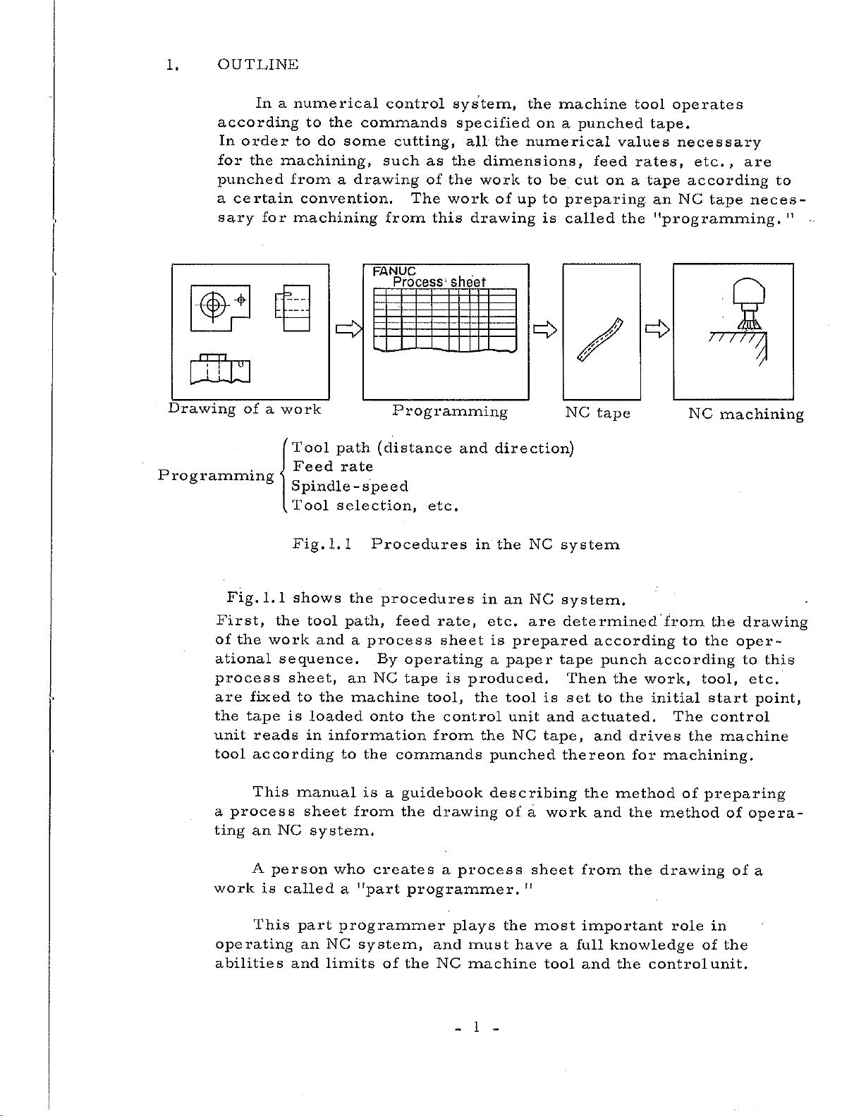
OUTLINE
SPECIFICATIONS
2.
2.
2.3
2.4
1
2
Basic
Basic
Additional
Outer
Unit
Option
View
CONTENTS
,
...
Options
.
OPERATOR’S
FUJITSU
..
FANUC
MANUAL
LTD
;
1
3
3
7
8
13
3.
1
PROGRAMMING
3.
3.
3.
3.4
3.
3.
3.7
3.8
3.9
3.
3.
3.11.1
3.11.2
3.11.3
1
2
3
5
6
10
11
General
Process
Tape
Increment
Buffer
Absolute
Maximum
Tape
Address
Function
Feed
Format
Code
Function
Rapid
1
-Digit
4
-Digit
,
.
Sheet
System
Register
and
Programmable
Codes
Codes
Traverse
F-Code
F-Code
. .
.
(Buffer)
Incremental
Speed
Unit
Unit
Programming
Dimensions
15
.
.
15
15
17
18
20
20
21
22
22
24
25
25
26
27
B-5
520E/06
1
Page 2
3.
12
Preparatory
Function
(G
Function)
30
3.
3.
3.
3.
3.
3.
3.
3.12.
3.
3.
3.
3.
3.
3.
3.
3.
3.
3.
3.
3.
3.
3.
3.
3.
3.
3.
3.23
3.
3.25
12.
12.
12.
12.4
12.
12.
12.
12.
12.
12.11
12.
12.
12.
12.
12.
13
14
15
16
17
18
19
20
21
22
24
1
Positioning
Linear
2
Circular
3
Dwell
Circle
5
6
Helical
G15),
7
Plane
8
Programming
9
10
12
13
14
Zero
Cutter
Tool
Tool
Canned
Absolute
G91)
Programming
15
Initial
16
D
Spindle
Tool
B
Miscellaneous
Automatic
Optional
Absolute
Mirror
Sequence
Label
Sub
Programming
H
and
Function
Function
Skip
Tape
-Speed
Interpolation
Interpolation
(G04)
Cutting
Interpolation
B(G02,G03)
Selection
Return
Compensation
Offset
Offset
Cycles
and
Level
Functions
Function
(T
Acceleration
Block
Rewind
image
Number
Function
Control
Examples
(GOO)
(G12,
Copy
(G27
B
(G43,
A
(G45
(G73,
Incremental
of
and
Function)
Function
Skip
Stop
Display
,
(G17
(G25)
,
G28,
to
Absolute
R
point
(S
(M
and
&
Reset
and
(G01)
(GO
G13)
Helical
G18,
G29)
(G38
G44,
G48)
G76,
Level
Function)
Function)
Deceleration
&
Search
Control
.....
2,
GO
3)
.
Interpolation
G19)
.
G42)
to
G49)
G80
Programming
Zero
In/Out
G89)
to
Point
(G98
and
.
(G90
(G92)
G99)
A(G14,
and
•
-
..
.
32
34
36
40
41
42
46
46
49
51
63
66
76
91
91
93
94
95
96
97
98
99
101
103
104
105
106
108
111
4.
:
;
i
1
OPERATION
4.1
4.1.1
4.1.2
4.1.
MDI
3
4.1.4
2
4.
4.
4.4
4.
3
5
4.5.
4.
4.5.3
5.
Position
1-Digit
Built-in
Tape
1
2
DPL
&
Display
Switch
Display
Manual
Display
F-Code
Type
Reader
Tape
Tape
Procedure
Reader
Reader
Unit
Section
and
Unit
Data
Button
Section
Input
Unit
Unit
Manual
without
with
of
Setting
Section
........
(MDI)
Operator's
Reels
Reels
NC
an
..
Section
.....
Tape
..
Panel
116
;
116
116
118
120
129
148
150
150
151
151
154
158
Page 3
4
4.7
Punch
6
.
Procedure
Operator's
of
Panel
Function
161
162
4.7.1
4.7.2
4.7.3
4.7.4
4.7.5
4.7.6
4.7.7
4.7.8
4.7.9
4.7.10
4.7.11
4.7.12
4.7.13
4.7.14
4.7.15
4.7.
4.7.
4.7.
4.7.
4.7.20
4.7.21
4.7.22
4.7.23
4.7.24
16
17
18
19
MODE
CYCLE
FEED
JOG
RAPID
DRY
OPTIONAL
F4
JOG
EMERGENCY
SINGLE
ZERO
Lamps
BLOCK
DISPLAY
Z-AXIS
MANUAL
SCALE
AUXILIARY
HANDLE
MANUAL
SEARCH
OVERRIDE
POWER
2ND
SELECT
HOLD
&
STEP
TRAVERSE
RUN
FEED
FEED
RETURN
L.S.
START
BLOCK
RETURN
FEED
RETURN
START
ON/OFF
Switch
Button
Button
Button
Switch
BLOCK
RATE
RATE
OVERRIDE
Dial
STOP
Switch
Switch
Switch
LOCK/MACHINE
NEGLECT
ABSOLUTE
Switch
FUNCTION
AXIS
and
PULSE
CANCEL
REMOVE
SELECT
MULTIPLY
Button
Button
Switch
...
SKIP
Button
and
Switch
Switch
Switch
..
.
.
.....
Switch
Switch
LOCK
Dial
ZERO
LOCK
Switch
.
Switch
Switch
.
.
.
.
.
POSITION
Switch
..
162
164
165
166
167
167
168
168
169
170
171
173
174
177
178
179
181
181
182
183
183
183
1
83
183
5.
*
6.
OPERATIONAL
1
5.
2
5.
5.
3
5.4
5
5.
6
5.
7
5.
5.8
5.9
10
5.
11
5.
MAINTENANCE
1
6.
2
6.
3
6.
Preparation
Power
Turning
Setting
Manual
Setting
Tape
NC
Manual
Operation
Operation
Preparation
Turning
Daily
P
ow
er
Fault
PROCEDURE
and
Inspection
....
.....
on
Power
T
ape
a
Operation
Zero
the
Point
Operation/Memory
Operation
MDI
by
the
by
before
Off
Power
Maintenance
Fuses
Causes
and
during
Unit
MDI
Remedies
before
. .
NC
.
Call
Tape
NC
Off
.....
during
Turning
Turning
.
Operation
Operation
Tape
Power
on
.
.
.
Operation
..........
......
.
185
.
185
185
185
.
188
190
191
192
192
.
.
192
192
192
193
193
194
195
Page 4
APPENDIXES
Appendix
Appendix
Appendix
Appendix
Appendix
Appendix
Appendix
1
2
3
List
Range
of
Nomographs
1
3.
Tape
of
3.2
4
5
6
7
Preparation
How
to
RESET
State
and
and
Operation
Join
Codes
Various
Error
Circular
Tool
of
NC
Display
in
Path
NC
Tape
Commands
the
Radius
Cutting
a
at
Corner
Tape
of
Control
Values
Direction
in
Unit/Mode
201
202
205
205
208
216
218
219
Selection
220
Page 5
1.
OUTLINE
In
according
order
In
for
the
punched
certain
a
sary
for
a
numerical
to
the
to
do
machining,
from
convention.
machining
commands
some
a
drawing
ccmtrol
cutting,
such
The
from
FANUC
Process;
as
of
this
system,
specified
all
the
dimensions,
the
work
work
drawing
sheet
the
of
the
on
numerical
to
be
up
to
is
machine
punched
a
feed
cut
preparing
called
values
on
operates
tool
tape.
rates,
tape
a
an
the
"programming.
necessary
etc.,
according
tape
NC
are
neces¬
to
"
-
ura
Drawing
P
rog
(id
ramming
Fig.
First,
of
the
ational
process
are
the
unit
tool
d
of
work
a
1.1
the
work
sequence.
fixed
tape
reads
according
Tool
Feed
path
rate
Spindle-speed
1.1
tool
and
to
the
loaded
in
information
selection,
the
path,
a
an
machine
to
the
Tool
Fig.
shows
sheet,
is
Programming
(distance
Procedures
procedures
feed
process
By
operating
tape
NC
onto
the
commands
etc.
rate,
sheet
tool,
control
from
and
is
produced.
direction)
in
the
in
an
etc.
is
paper
a
the
tool
unit
the
punched
NC
NC
are
prepared
is
and
NC
tape,
NC
tape
system
system.
determined
according
tape
punch
Then
set
thereon
the
to
actuated.
and
the
drives
for
o
from
to
according
work,
initial
The
machining.
77777
NC
the
the
tool,
start
control
the
$
machining
drawing
oper¬
to
this
etc.
point,
machine
This
process
a
an
ting
A
work
This
operating
abilities
NC
person
is
manual
sheet
called
part
an
and
system.
who
a
programmer
NC
limits
is
from
creates
"part
system,
of
guidebook
a
the
drawing
programmer.
the
a
and
NC
process
plays
must
machine
1
describing
of
a
sheet
"
most
the
have
work
a
tool
the
method
and
from
important
full
knowledge
and
the
the
the
method
drawing
role
control
of
preparing
of
of
in
the
unit.
opera¬
of
a
Page 6
For
example,
he
must
select
(1)
select
(2)
effectively
(3)
(4)
(5)
the
give
point,
effectively
Also,
high-accuracy
tool,
Setting
to
setting
addition
the
(1)
resetting
Giving
(2)
(3)
Daily
such
the
tool
a
optimum
use
operator
,
etc.
use
operator
the
products,
the
usual
the
Cutter
the
because
instructions
maintenance
path
spindle
M
the
information
the
Canned
of
pay
operations
tape,
Compensation
the
of
about
(cleaning
as
to
function
NC
an
attention
operating
tool
regrinding
reduce
speed,
or
on
Cycle,
system
(loading
wear,
and
the
tool
and
function,
G
the
tool
etc.
must,
to
the
and
the
control
amount
etc.)
the
inspection)
machining
feed
change,
order
in
following
unloading
panel,
(requiring
tool
time,
rate,
machine
points
the
etc.)
the
to
work
produce
setup
in
and
periodical
The
front
its
Particularly
doors
outside
centers,
the
positioning
centers,
(including
This
machine
The
operator
and
enter
air
manual
milling
FANUC
and
etc,
back
in
a
that
tool
continuous
and
does
doors
usual
of
directly
discusses
machines,
builder
C
3000
used
not
need
open
operation,
the
tape
into
the
etc.
to
as
NC
are
cutting
FANUC
to
except
he
reader)
it.
equipment
Refer
which
equipped
for
DC
operate
for
rather
options
milling
servo
the
the
closed
with
the
to
with
motor
equipment
NC
maintenance.
operates
so
as
options
description
be
can
2-to
machines,
used
4-axis
series
with
it
not
for
machining
as
with
the
to
let
machining
issued
in
practice.
the
the
by
servo.
2
Page 7
2.
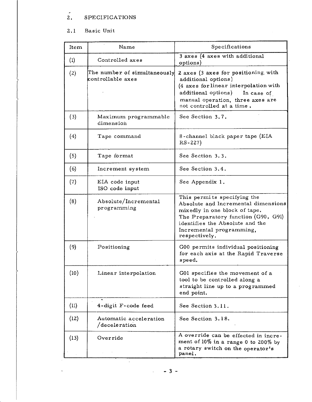
SPECIFICATIONS
2.1
Item
(1)
(2)
(3)
(4)
(5)
(6)
Basic
Controlled
The
number
controllable
Maximum
dimension
Tape
Tape
Increment
Unit
Name
axes
of
axes
programmable
command
format
system
simultaneously
axes
3
options)
axes
2
additional
(4
axes
additional
manual
not
controlled
See
Section
-channel
8
RS-227)
See
Section
See
Section
Spe
(4
axes
_
axes
(3
options)
linear
for
options)
operation,
black
cifications
with
for
at
3.7.
3.3.
3.4.
additional
positioning
interpolation
In
three
time
a
paper
tape
case
axes
.
with
with
of
are
(EIA
(?)
(8)
(9)
(10)
(11)
(12)
EIA
code
ISO
code
Absolut
programming
Positioning
Linear
4-digit
Automatic
deceleration
/
e/lnc
interpolation
F-code
input
input
remental
feed
acceleration
See
Appendix
This
permits
Absolute
mixedly
Preparatory
The
identifies
Incremental
respectively.
permits
GOO
each
for
speed.
specifies
G01
to
tool
straight
end
See
See
be
point.
Section
Section
and
Incremental
one
in
the
programming,
individual
axis
controlled
line
up
3.11.
3.18.
1
.
specifying
block
function
Absolute
the
at
the
movement
to
a
the
dimensions
of
tape.
(G90,
the
and
positioning
Rapid
along
programmed
Traverse
a
of
G91)
a
(13)
Override
A
override
ment
a
panel
3
-
-
of
rotary
.
10%
switch
can
in
a
be
range
on
effected
0
the
operator's
to
in
incre¬
200%
by
Page 8
Item
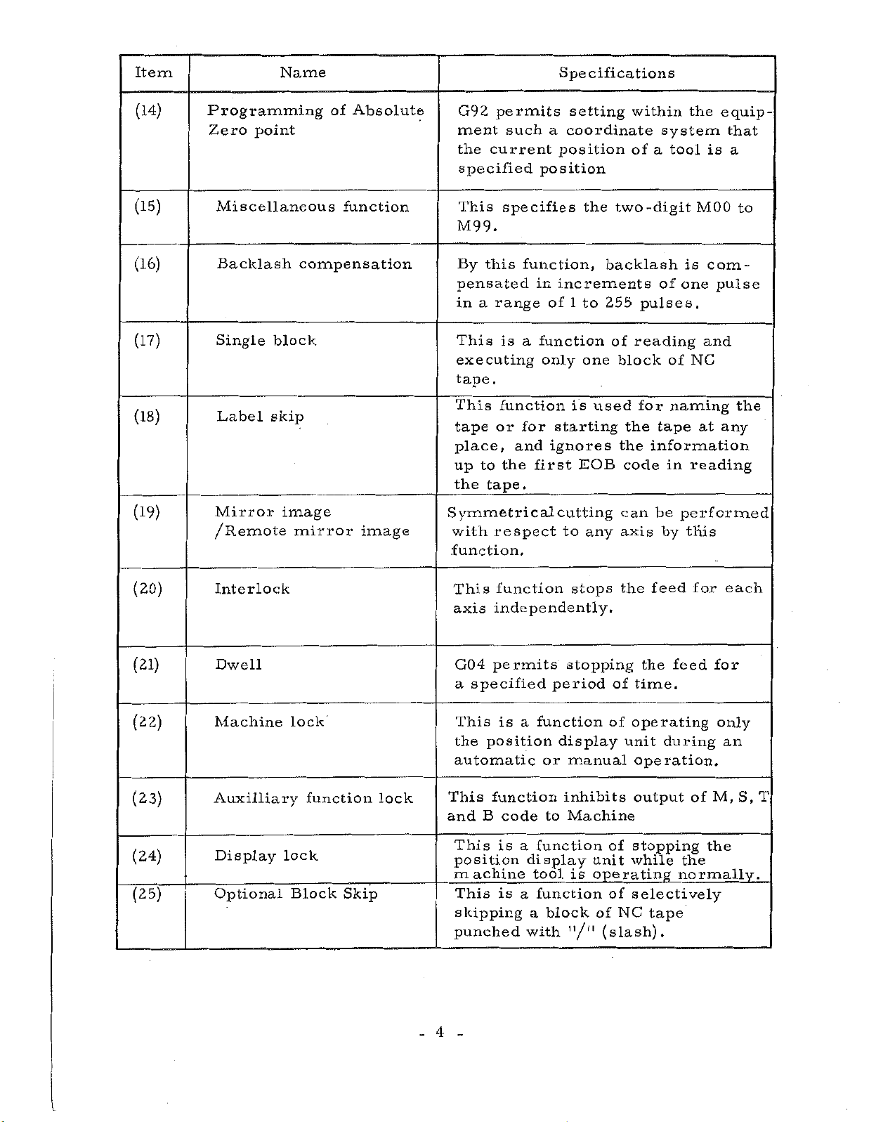
(14)
Name
Programming
Zero
point
of
Absolute
permits
G92
ment
the
current
specified
such
Specifications
setting
a
coordinate
position
position
within
of
a
the
system
tool
equip¬
is
that
a
(15)
(16)
(17)
(18)
(19)
(20)
Miscellaneous
Backlash
Single
Label
Mirror
block
skip
image
/Remote
Interlock
function
compensation
mirror
image
This
specifies
M99.
this
By
pensated
a
in
range
This
executing
tape.
This
tape
place,
up
the
Symmetrical
with
is
function
or
the
to
tape.
respect
function.
This
axis
function
independently.
function,
in
of
a
function
only
for
ignores
and
first
the
backlash
increments
1
to
255
one
used
is
starting
EOB
cutting
to
any
stops
two-digit
pulses.
of
reading
block
for
the
the
information
code
can
axis
feed
the
is
one
of
of
naming
tape
in
be
performed
by
MOO
com¬
pulse
and
NC
at
reading
this
for
to
the
any
each
(21)
(22)
(23)
(24)
(25)
Dwell
Machine
Auxilliary
Display
Optional
lock
lock
Block
function
Skip
lock
G04
a
This
the
automatic
This
and
This
position
machine
This
skipping
punched
4
permits
specified
is
position
function
B
code
is
is
a
function
or
to
a
function
display
tool
function
a
block
a
with
stopping
period
display
manual
inhibits
Machine
is
"/"
of
time.
of
operating
unit
operation.
output
of
stopping
unit
while
operating
of
selectively
NC
of
(slash).
the
tape
feed
during
of
the
normally.
for
M,
the
only
an
S,
T
Page 9

Item
(26)
(27)
(28)
(29)
Manual
feed
JOG
STEP
MDI
feed
feed
h
Name
rapid
DPL
traverse
This
tool
TRAVERSE
in
by
This
tool
kept
mode
This
tool
when
in
SELECT
See
function
rapidly
the
the
function
while
pushed
function
to
the
Section
manual
MODE
by
XI,
the
step
Specifications
feed
can
while
button
continuous
SELECT
feed
can
the
JOG/
the
in
MODE
the
can
feed
,
X10
JOG/
feed
switch.
X100
STEP
mode
4.1.1
RAPID
the
is
kept
STEP
manual
SELECT
,
button
by
the
feed
switch.
the
button
the
X1000
the
machine
pushed
mode
machine
is
continuous
switch.
machine
pulses
is
pushed
MODE
(30)
(31)
(32)
(33)
(34)
(35)
Override
Z-axis
cancel
Tool
offset
Sequence
Remote
Remote
cancel
command
A
number
deceleration
power
search
ON/OFF
This
enable
Override
During
operation
can
be
This
for
This
to
number
This
rate
The
by
addition
button
panel.
is
a
feature
search
function
from
power
contact
a
a
made
a
cutter
on
on
the
fix
cycle
command
a
function
length.
any
tape.
outside,
is
signal
to
the
the
4
-digit
to
100%.
operation
to
be
ignored.
of
enables
following
decelerates
turned
POWER
control
F-code
or
the
for
compensating
operater
the
sequence
the
on
and
from
outside
ON/OFF
display
unit
feed
manual
Z-axis
feed
off
in
(36)
Buffer
register
5
-
This
mitting
executed,
ahead
NC
permits
tape.
pulses
during
continuously
between
by
reading
the
one
operation
blocks
block
trans¬
an
by
being
Page 10
Item
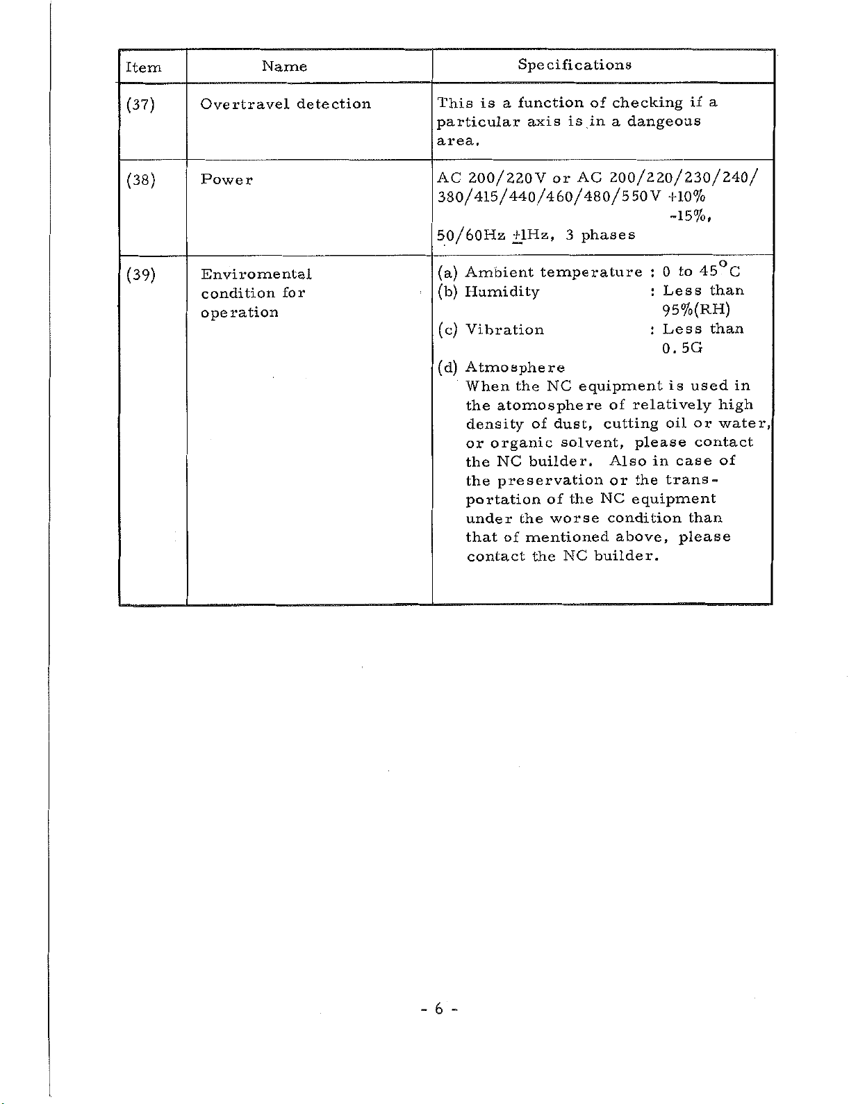
(37)
Overtravel
Name
detection
This
particular
is
area.
Specifications
function
a
axis
a
checking
of
is
in
a
dangeous
if
(38)
(39)
Power
Enviromental
condition
operation
for
AC
200/220V
380/415/440/460/480/550V
or
AC
200/220/230/240/
+10%
-15%,
3
50/60Hz
Ambient
(a)
Humidity
(b)
+lHz,
temperature
phases
:
:
to
0
Less
45°C
than
95%(RH)
5G
is
case
please
than
used
or
contact
than
(c)
Vibration
Atmosphere
(d)
When
the
density
or
the
the
portation
under
that
contact
NC
the
atomo
organic
NC
preservation
of
sphere
of
builder.
of
the
mentioned
the
equipment
dust,
solvent,
the
worse
NC
of
cutting
Also
or
NC
equipment
condition
above,
builder.
Less
:
0.
relatively
oil
please
in
trans¬
the
in
high
water,
of
6
-
-
Page 11
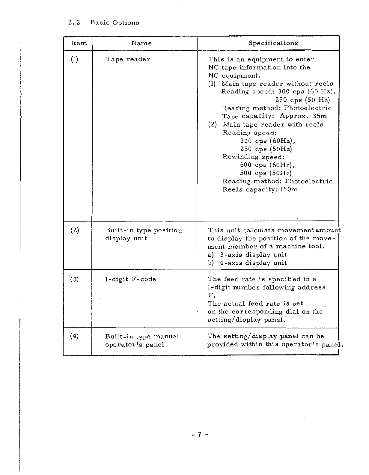
2.2
Basic
Options
Item
(1)
Tape
Name
reader
This
NC
NC
(1)
(2)
is
an
tape
information
equipment.
Main
Reading
Reading
Tape
Main
Reading
tape
capacity:
tape
300
250
Rewinding
600
500
Reading
Reels
Specifications
equipment
reader
speed:
250
method:
reader
speed:
cps
(60Hz),
(50Hz)
cps
speed:
cps
(60Hz)
(50Hz)
cps
method:
capacity:
to
enter
into
the
without
300
cps
cps
Photoelectric
Approx.
with
,
Photoelectric
150m
(60
(50
reels
reels
Hz),
Hz)
35m
(2)
(3)
(4)
Built-in
display
1-digit
Built-in
operator's
type
unit
F-code
type
position
manual
panel
This
to
ment
a)
b)
The
1
-digit
display
-axis
3
4
-axis
feed
calculats
unit
member
rate
number
the
display
display
F.
The
on
actual
the
feed
corresponding
setting/display
setting/
The
provided
within
position
of
is
following
rate
panel.
display
this
movement
machine
a
unit
unit
specified
is
dial
panel
operator's
of
set
move¬
the
tool.
a
in
address
on
the
can
amount
be
panel.
7
-
-
Page 12
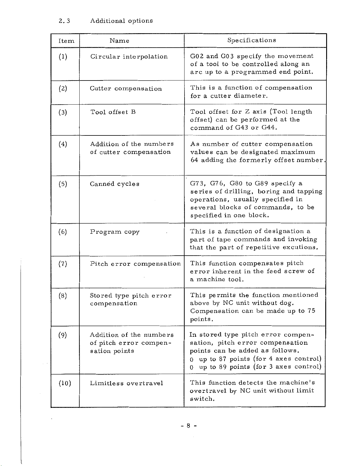
2.
3
Additional
options
Item
(1)
(2)
(3)
(4)
(5)
Circular
Cutter
Tool
Addition
cutter
of
Canned
Name
interpolation
compensation
offset
B
of
the
compensation
cycles
numbers
GO
2
and
of
tool
a
up
arc
This
for
Tool
a
is
cutter
offset
offset)
command
number
As
values
adding
64
3,
G7
series
operations,
several
specified
G7
Specifications
3
GO
to
be
a
to
programmed
function
a
diameter.
for
can
be
G43
of
of
be
can
the
6,
G80
of
drilling,
usually
blocks
in
one
specify
controlled
of
Z
axis
performed
or
cutter
designated
formerly
to
G89
commands,
of
block.
movement
the
along
end
compensation
(Tool
at
G44.
compensation
maximum
offset
specify
boring
specified
and
point.
length
the
number.
a
tapping
in
to
an
be
(6)
(?)
(8)
(9)
(10)
Program
Pitch
Stored
compensation
error
type
Addition
pitch
of
sation
Limitless
error
points
copy
compensation
pitch
the
of
overtravel
error
numbers
compen¬
This
part
that
This
error
a
This
above
Compensation
points
In
sation,
points
0
0
This
overtravel
switch.
is
of
the
function
inherent
machine
permits
by
.
stored
can
to
up
to
up
function
a
tape
part
pitch
87
89
function
commands
of
compensates
tool.
the
NC
unit
type
error
be
added
points
points
detects
by
repetitive
the
in
function
without
can
pitch
(for
(for
NC
unit
of
designation
and
feed
dog.
made
be
error
compensation
as
follows.
axes
4
3
axes
the
machine's
without
invoking
excutions.
pitch
screw
mentioned
to
up
compen¬
control)
control)
limit
a
of
75
8
-
-
Page 13
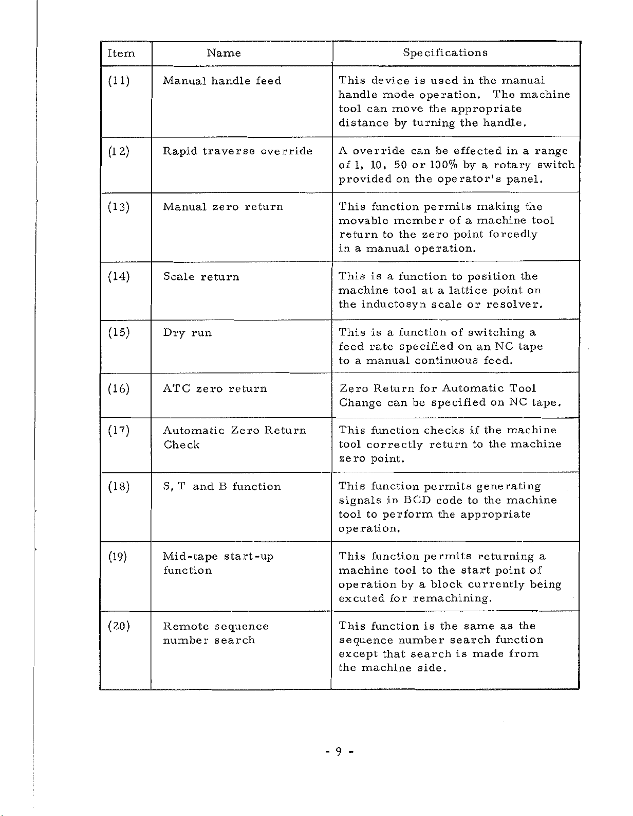
Item
Name
Specifications
(11)
2)
(1
(13)
(14)
(15)
Manual
Rapid
Manual
Scale
Dry
traverse
return
run
handle
zero
feed
override
return
This
handle
tool
can
distance
A
override
1,
of
provided
This
movable
return
a
in
manual
This
machine
inductosyn
the
This
feed
to
a
manual
device
mode
move
by
10,
50
on
function
member
to
is
function
a
tool
function
is
a
rate
is
used
operation.
the
turning
can
or
100%
the
permits
zero
the
operation.
at
scale
specified
continuous
in
appropriate
the
be
effected
by
operator's
of
a
point
to
position
lattice
a
or
of
switching
on
the
manual
The
handle.
rotary
a
making
machine
forcedly
point
resolver.
NC
an
feed.
machine
in
a
panel.
the
tape
range
switch
the
tool
on
a
(16)
(17)
(18)
(19)
(20)
ATC
zero
Automatic
Check
T
S,
Mid
and
-tape
function
Remote
number
return
Zero
B
function
start-up
sequence
search
Return
Zero
Change
This
tool
zero
This
signals
tool
operation.
This
machine
operation
excuted
This
Return
function
correctly
point.
function
to
function
function
sequence
except
the
machine
can
BCD
in
perform
tool
by
for
number
search
that
for
Automatic
be
specified
checks
return
permits
code
the
appropriate
permits
start
the
to
block
a
remachining.
is
the
search
is
side.
on
the
if
to
the
generating
to
the
returning
currently
same
made
Tool
NC
machine
machine
machine
point
the
as
function
from
tape.
a
of
being
-9-
Page 14
Item
Name
Specifications
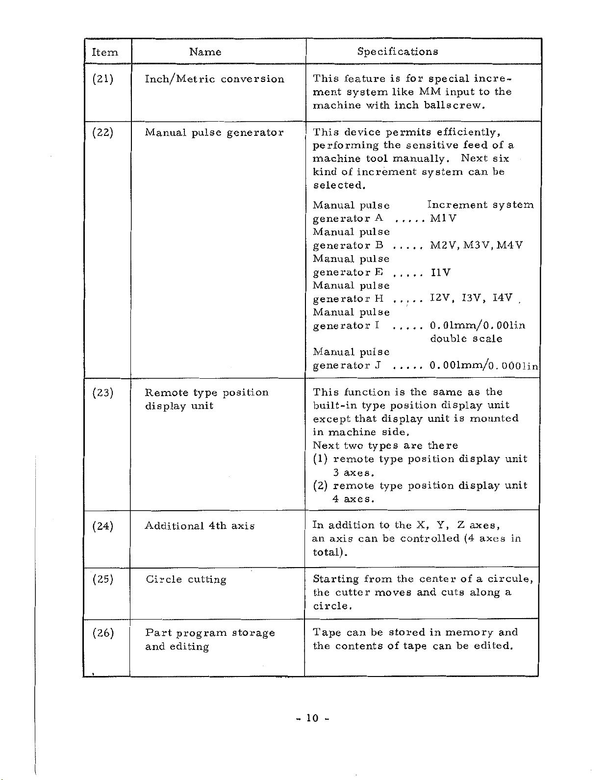
(21)
(22)
Inch/Metric
Manual
pulse
conversion
generator
This
ment
machine
This
performing
machine
kind
selected.
Manual
generator
Manual
feature
system
device
of
generator
Manual
generator
Manual
generator
Manual
generator
Manual
generator
is
with
permits
the
tool
increment
pulse
A
pulse
B
pulse
E
pulse
H
pulse
I
pulse
J
special
for
MM
like
inch
ballscrew.
sensitive
manually.
system
Increment
incre¬
input
efficiently,
to
feed
Next
can
V
Ml
M2V,
I1V
1
0
double
0.
M3V.M4V
2V,
I3V,
.
01mm/
scale
OOlmm/o.
the
of
six
be
system
I4V
.
OOlin
0
a
.
OOOlin
(23)
(24)
(25)
(26)
Remote
display
Additional
Circle
Part
and
program
editing
type
unit
4th
cutting
position
axis
storage
This
built-in
except
machine
in
Next
(1)
remote
3
remote
(2)
4
addition
In
axis
an
total)
Starting
cutter
the
circle.
Tape
contents
the
function
type
that
two
types
axes.
axes.
can
.
from
be
can
is
position
display
side.
type
type
to
the
be
the
moves
stored
of
same
the
unit
there
are
position
position
X,
controlled
center
and
in
can
tape
display
is
Y,
Z
cuts
memory
be
as
mounted
display
display
axes,
(4
axes
a
of
along
edited.
the
unit
unit
unit
in
circule,
a
and
-
10
-
Page 15
Item
Name
Specifications
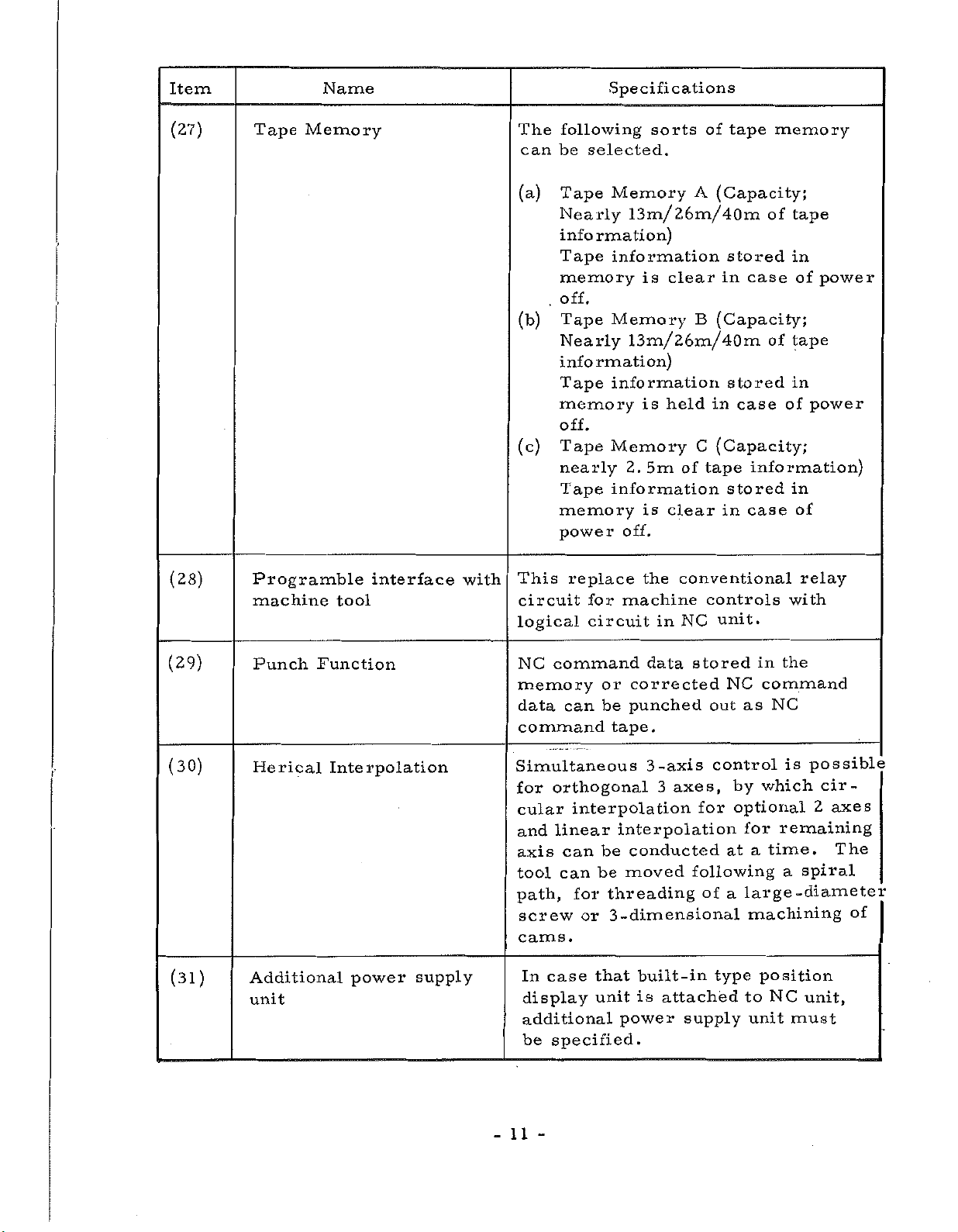
(27)
(28)
Tape
Prog
machine
ramble
Memory
tool
interface
with
The
following
can
be
(a)
Tape
Nearly
information)
Tape
memory
off.
.
(b)
Tape
Nearly
information)
Tape
memory
off.
(c)
Tape
nearly
Tape
memory
power
This
circuit
logical
selected.
replace
for
circuit
sorts
Memory
tape
of
A
(Capacity
13m/26m/40m
information
is
clear
Memory
stored
in
B
(Capacity;
case
13m/26m/40m
in
(Capacity;
C
tape
of
controls
unit.
NC
stored
case
stored
in
case
information
held
is
Memory
5m
2.
information
is
clear
off.
conventional
the
machine
in
memory-
;
tape
of
in
of
power
of
tape
in
power
of
information)
in
of
relay
with
(29)
(30)
(31)
Punch
Herical
Additional
unit
Function
Interpolation
power
supply
NC
command
memory
data
Simultaneous
for
cular
and
axis
tool
path,
can
command
orthogonal
interpolation
linear
can
can
for
screw
or
cams.
case
In
display
additional
be
that
unit
specified.
data
or
corrected
punched
be
tape.
-axis
3
3
interpolation
conducted
be
moved
be
threading
-dimensional
3
built-in
is
power
stored
axes,
for
following
of
attached
supply
NC
out
control
by
optional
at
a
type
the
in
command
NC
as
is
which
remaining
for
time.
a
a
position
NC
unit
-diameter
must
large
machining
to
possible
cir¬
2
axes
The
spiral
unit,
of
11
-
Page 16
Item
Name
Specifications
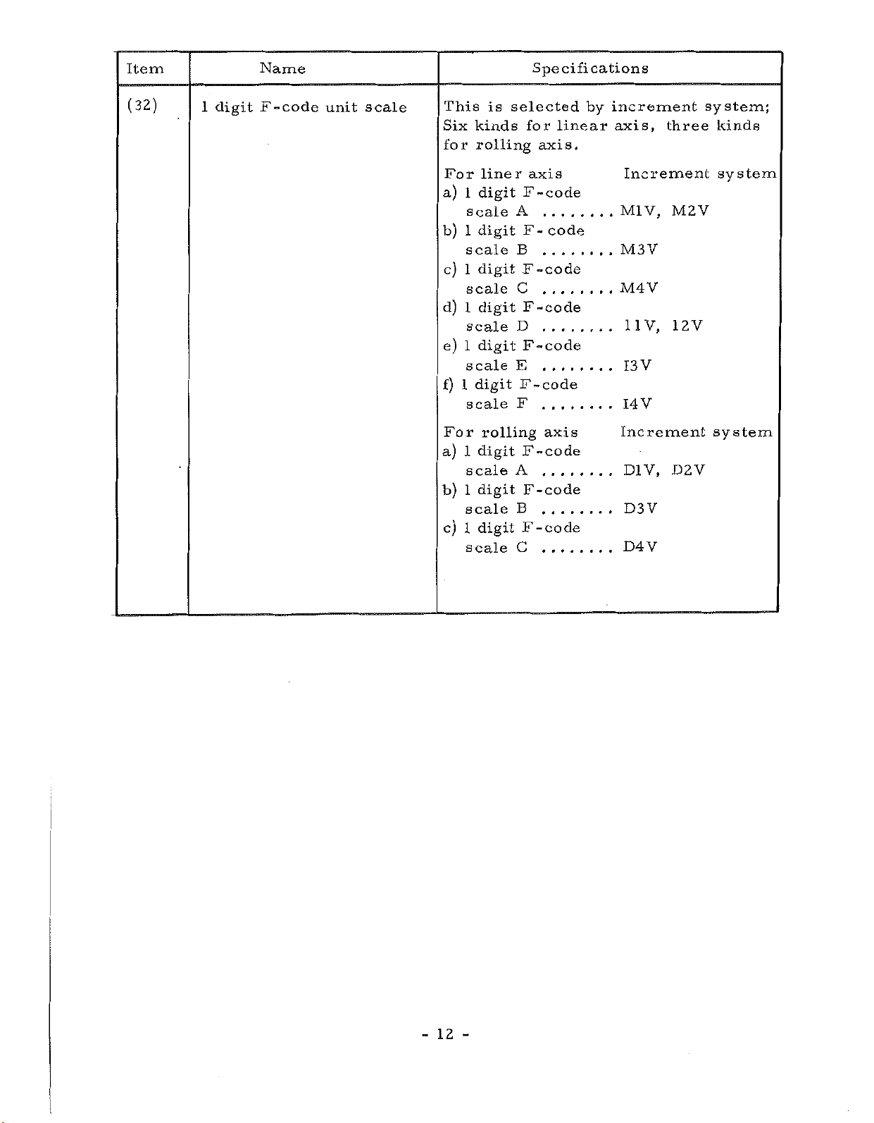
(32)
1
digit
F-code
unit
scale
This
Six
for
For
a)
b)
c)
d)
e)
f)
For
a)
b)
c)
1
1
1
1
1
1
1
1
is
kinds
rolling
lineraxis
digit
scale
digit
scale
1
digit
scale
digit
scale
digit
scale
digit
scale
rolling
digit
scale
digit
scale
digit
scale
selected
for
axis.
F
-code
A
.....
F
code
-
B
F
-code
C
.....
F-code
D
F
-code
E
F
-code
F
axis
F
-code
A
F-code
B
F
-code
C
linear
by
increment
axis,
Increment
V,
Ml
M3Y
M4V
11V,
V
13
V
14
Increment
D1V,
D3V
D4V
three
M2V
12V
D2V
system;
kinds
system
system
12
-
-
Page 17
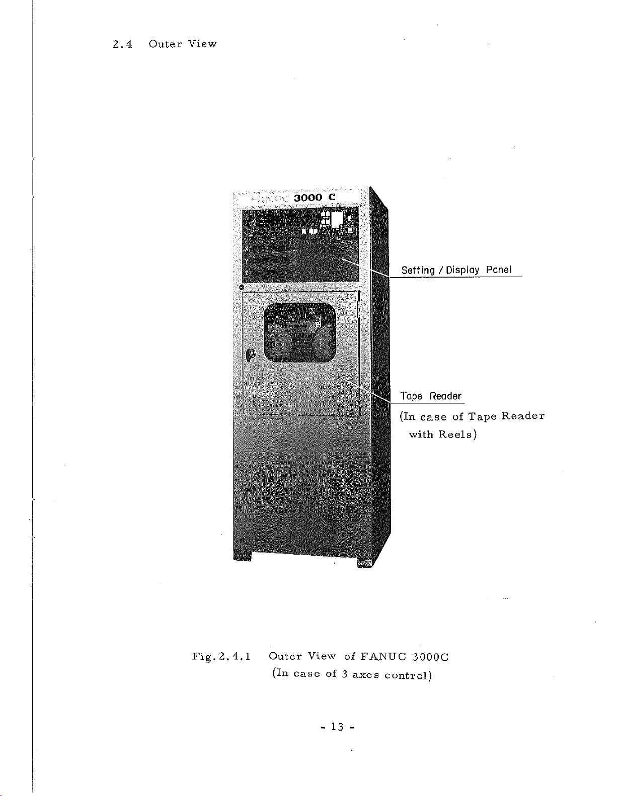
2.4
Outer
View
'4
x
p
1
•
—
:
P
.
I
3000
iv
J.
C
::p-
"
-
s
1
.
::
I
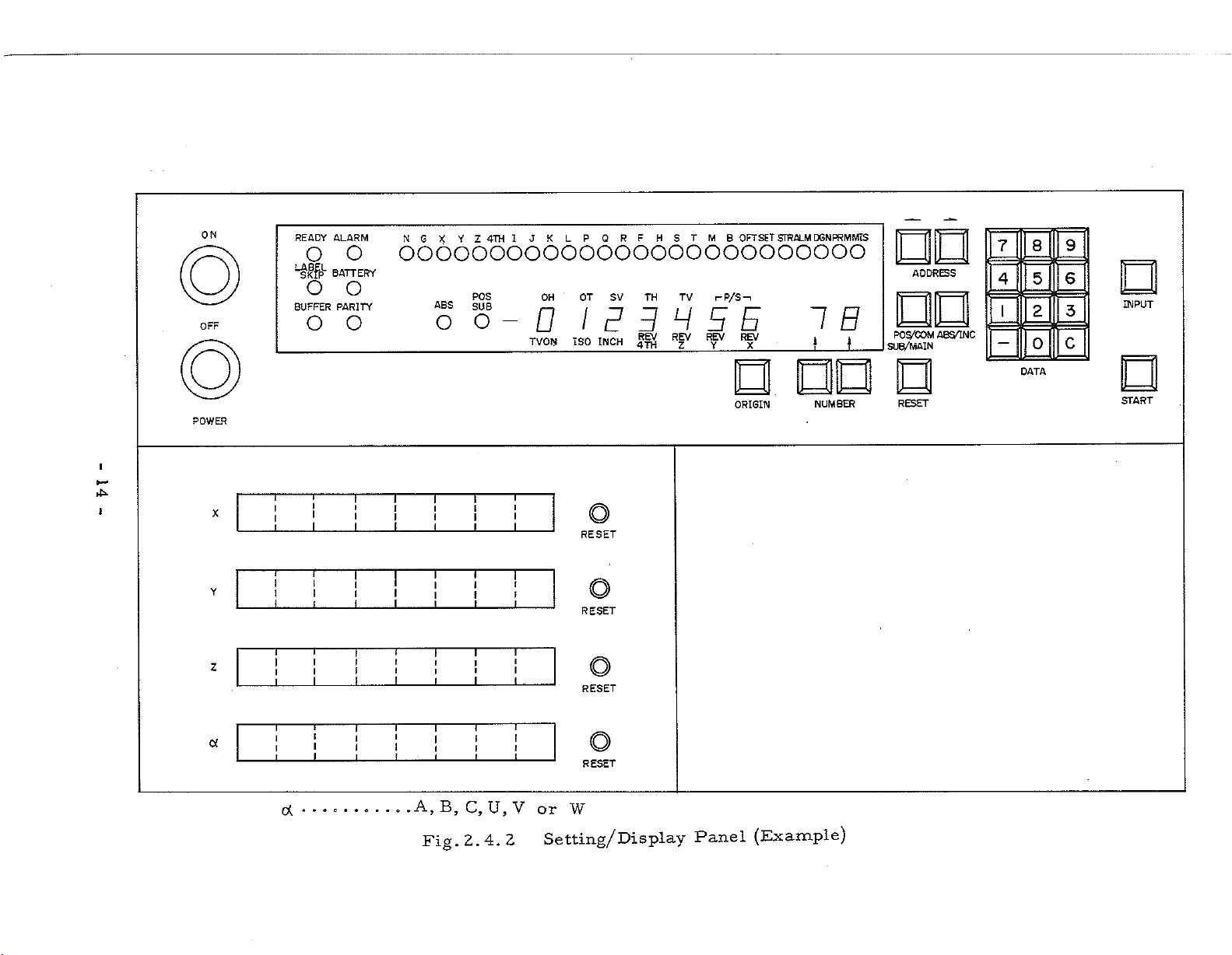
Setting
Tape
(in
case
with
Display
/
Reader
of
Reels)
Tape
Panel
Reader
Fig.
2.4.1
m
Outer
(in
case
View
-
of
13
of
3
-
FANUC
axes
3000C
control)
Page 18
ON
OFF
READY
o
LABEL
SKIP
o
BUFFER
o
ALARM
o
BATTERY
o
PARITY
o
NG
XYZ
4TH
LP
QRF
HSTMB
OFTSET
JK
I
STRALM
DGNPRMMIS
oooooooooooooooooooooooooo
POS
OH
OT
SV
oo-OIPBHEE
ISO
TVON
INCH
TH
REV
4TH
TV
REV
Z
i-P/S-.
REV
Y
REV
X
IB
_
J
t
ADDRESS
PO
A8S/1NC
S/COM
SUB/MAIN
8
5
2
0
DATA
9
6
INPUT
E
c
7
4
I
NUMBER
Panel
ORIGIN
(Example)
POWER
I
4ÿ
!
X
Y
Z
a
T
T
I
1
T
1
1
T
I
l
1
I
i
1
(X
T T
i
I
i
I
T
1
1
I
f
I
i
1
T
T
i
f
f
I
I
T
T
I
J
i
i
I
1
T
1
I
I
1
I
T
II
I
T
T
r
r
l
f
I
1
T
I
i
I
I
1
A,
B,
2.4.
Fig,
T
1
I
T
I
f
I
i
T
\
F
1
C,U,V
T
RESET
I
i
I
I
T
i
1
T
I
i
2
RESET
RESET
RESET
W
or
Setting/Display
O
o
RESET
START
Page 19
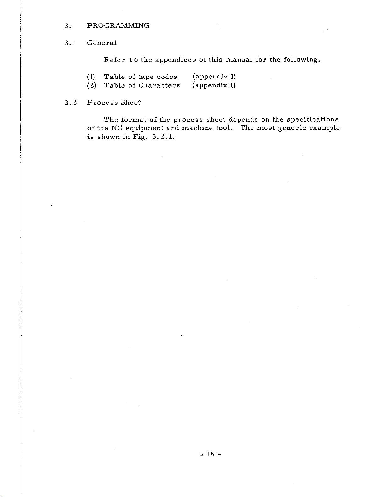
3.
PROGRAMMING
3.1
3.2
General
Refer
(l)
Table
(2)
Table
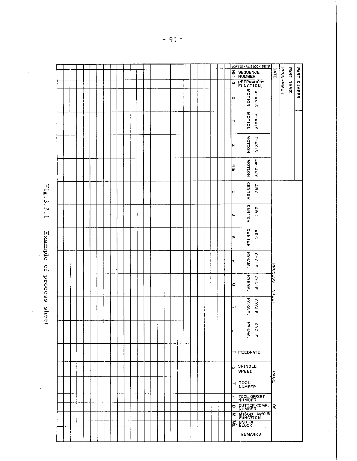
Process
The
of
the
shown
is
Sheet
format
NC
the
to
tape
of
Characters
of
equipment
in
Fig.
appendices
codes
of
the
and
3.2.1.
process
machine
this
of
(appendix
(appendix
sheet
tool.
manual
1)
l)
depends
The
for
on
most
the
following.
the
specifications
generic
example
15
-
Page 20
OQ
4
M-
u>
TO
w
B
CD
0
H-,
o
o
CD
03
03
03
CD
CD
c+
"
91
-
BLOCK
OPTIONAL
\
SEQUENCE
£
NUMBER
-
Q
PREPARATORY
FUNCTION
X
-<
N
M
c_
T3
o
23
r
SKIP
5
x
o
i
H
HH
X
o
S
X
O
'
H
>
X
o
CO
z
S
N
i
o
>
H
X
n
o
(0
z
s
$
p-
O
I
H
J>
hH
2
2
z
to
o
)>
m
2>
z
O
H
m
XJ
o
m
>
X)
z
O
H
m
X3
O
>
m
23
Z
o
H
m
23
V
o
X)
o
>
r
5
m
T>
O
>
X
X3
O
>
r
5
m
~o
O
>
X
X)
o
r
S
m
T3
o
X>
X
23
O
>
r
2
m
X)
X)
o
m
(O
CO
<o
x
rn
m
H
"0
o
S
t*
X3
->
2)
xt
o
H
G)
m
X>
5
n
X)
t
H
—
z
z
c
s
£
CD
m
m
X>
TI
FEEDRATE
SPINDLE
w
SPEED
TOOL
H
NUMBER
TOOL
X
o
S
ft
OFFSET
NUMBER
CUTTER
COMP.
NUMBER
MISCELLANEOUS
FUNCTION
OF
END
BLOCK
REMARKS
U
CD
PI
O
-n
Page 21
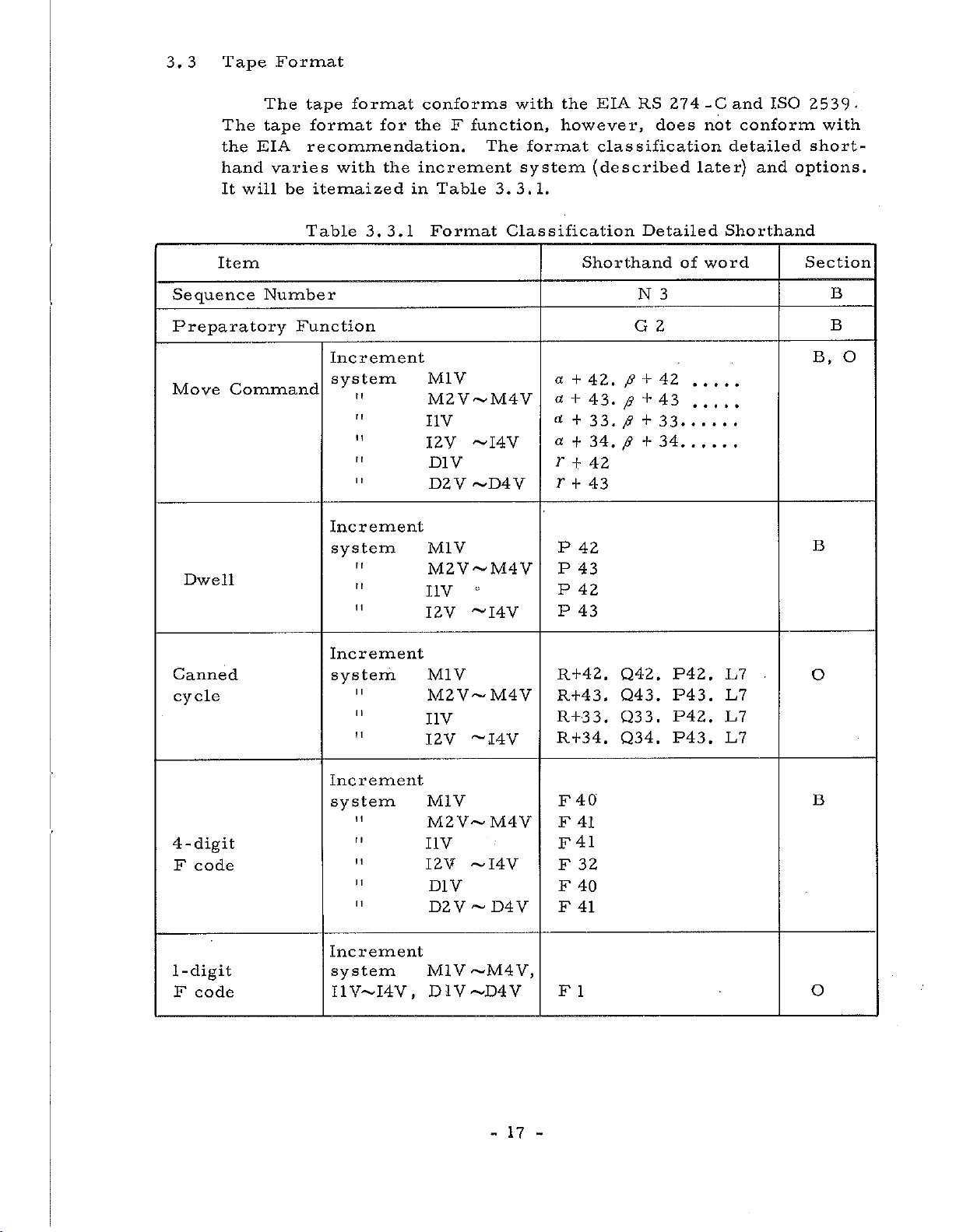
3.
Tape
3
Format
The
the
hand
It
Item
Sequence
Preparatory
Move
Command
Dwell
EIA
will
tape
The
format
tape
recommendation.
varies
itemaized
be
Table
Number
Function
format
for
with
the
3.3.1
Increment
system
"
Increment
system
t
r
(
r
1
1
conforms
the
F
increment
Table
in
Format
M1V
M2V~M4V
I1V
12V
D1V
D2V
M1V
M2V~M4V
I
IV
I2V
with
function,
The
3. 3.
Classification
~I4V
~D4V
~I4V
format
system
1.
a
a
«
cc
r
EIA
the
however,
classification
(described
Shorthand
+
42.
+
43.
+
33.
34,
+
42
+
r
43
+
P
42
P
43
P
42
P
43
RS
Detailed
N
G
p
+
+
p
p
+
p
+
274
does
3
2
42
43
33
34
of
-C
not
later)
Shorthand
word
ISO
and
conform
detailed
and
2539-
with
short¬
options.
Section
B
B
B,
B
O
Canned
cycle
4-digit
F
code
1-digit
code
F
Increment
system
I
I
1
I
!
1
Increment
system
"
Increment
system
I4V,
I1V—
M1V
M2V-M4V
IV
I
~I4V
I2V
M1V
M2V~M4V
I1V
I2V
~I4V
D1V
D2V
M1V
D1V-D4V
D4V
~
~M4
V,
R+42.
R+43.
R+3
R+34.
40
F
F
41
41
F
32
F
F
40
F
41
F
1
Q42.
Q43.
Q3
3
.
Q34.
P42.
P43
.
3
.
P42.
P43.
E7
L7
L7
L7
.
O
B
O
17
-
Page 22

Item
Shorthand
of
word
Section
Tool
Offset/Cutter
S
Function
T
Function
M
Function
B
Function
Note:
a
(1)
(2)
(3)
(4)
and
T
stands
Leading
Number
Both
Cutter
(0~63)
Compensation.
Compensation
p
stand
for
any
zeros
(N3)
.
D
and
H
Compensation
set
codes
can
for
of
can
be
commanded
any
A,
always
can
number.
of
B
be
and
be
HZ
or
S2
or
or
T2
M2
B3
X,
Y,
C.
omitted
specified
Maximum
for
D2
S4
T5
Z,
Tool
U,
except
on
V,
the
32
offset
W,
for
Tool
(0
I,
Sequence
Offset
~3l)
and
and
J
or
Cutter
B,
O
O
B
O
O
K
/
64
3.4
How
(5)
Among
B
With
(6)
can
the
{V
With
and
to
see
Example:
Increment
function,
the
be
expanded
B
function
the
program
detailed
a
System
S
function
optional
options
a
a
4-
is
5
means
point.
2
means
only
is
copy
shorthand.
52
+
any
is
a
sign.
4
of
function
one
B
function
to
up
not
effective.
of
circule
added,
the
of
a
maximum
two
digits
digits
five
addresses
and
added,
digits.
cutting,
above
of
below
T
selectable.
is
tape
five
function
the
In
helical
X,
digits
the
S
and
this
format
Y,
decimal
5
of
T
functions
case,
interpolation
changes.
Z
and
above
point.
digits
however,
etc.
the
decimal
and
The
increment
system
is
determined
18
-
by
the
following
elements:
Page 23

(1)
Least
input
increment
(2)
This
on
or
pulse
and
deg.
Least
This
is
NC
is
transmitted
is
mm/p,
of
Any
MDI
Increment
system
setting.
builder
M1V
M2V
the
least
tape
or
command
movement
the
the
least
inch/p
the
increment
the
for
unit
on
the
increment
unit
or
Refer
actual
Table
Least
inc
0.01
0.001
of
MDI
amount
from
in
deg./p.
systems
to
increment
3.4.1
rement
movement
unit.
NC
the
which
the
description
input
mm
mm
amount
This
machine
of
equipment
it
moves.
shown
system.
Increment
is
expressed
tool
to
This
in
Table
issued
Systems
Least
increment
0.001
0.001
that
can
for
the
is
3.4.1
by
command
mm/
mm/
be
specified
in
mm,
one
command
machine
expressed
is
the
machine
p
p
inch
tool,
selected
in
by
tool
M3V
M4V
I1V
I2V
I3V
I4V
D1V
D2V
D3V
D4V
When
the
increment
Increment
Therefore
speed
of
X-axis.
cutter
or
compensation
feed
number
the
0.001
0.001
0.001
0.
0
0.
0.01
0.001
0.
0.001
system
system
rate,
0001
0001
.
0001
001
of
offset
of
mm
mm
inch
inch
inch
inch
deg.
deg.
deg.
deg.
of
X,
X-axis
pulses
or
circular
Y
and
amount,
according
is
0.0005
0.0002
0.0001
0.0001
0.00005
0.00002
0.001
0.001
0.0005
0.0002
interpolation
Z-axis
regarded
are
etc
to
mm/
mm/
inch/p
inch/p
inch/p
inch/p
deg/p
deg/p
deg/p
deg/p
must
as
a
changed
the
increment
p
p
selected,
is
same.
be
fundamental.
into
pulse
system
for
Be
other
careful
than
the
of
X-axis.
designation
19
-
-
of
feed
rate
and
offset
amount
Page 24
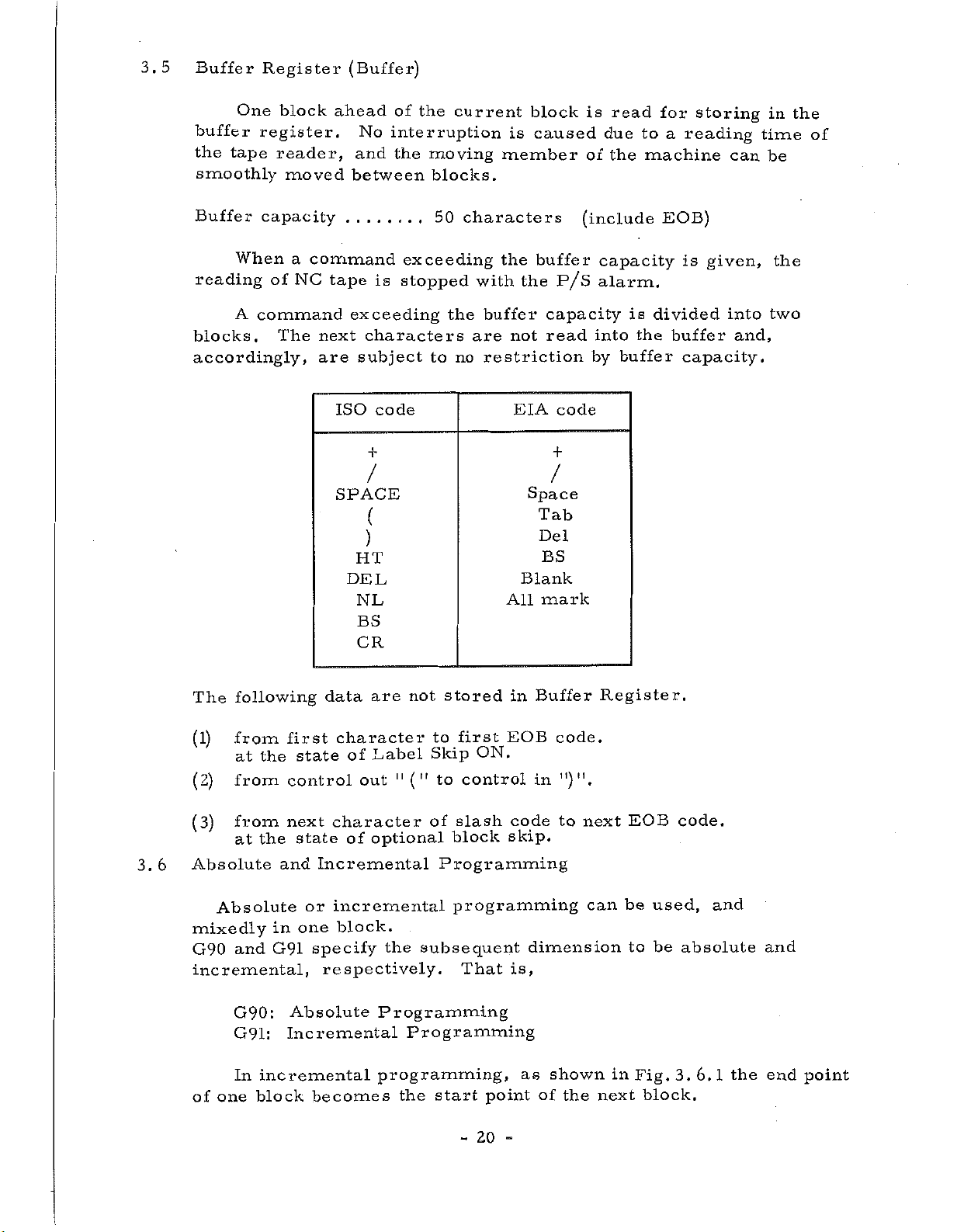
3.5
Buffer
One
buffer
the
tape
smoothly
Register
block
register.
reader,
moved
(Buffer)
ahead
No
and
between
of
the
current
interruption
the
moving
blocks.
block
is
caused
member
is
of
read
due
the
for
to
a
machine
storing
reading
can
in
time
be
the
of
Buffer
capacity
When
reading
A
command
blocks.
accordingly,
of
The
command
a
NC
next
are
tape
exceeding
characters
subject
ISO
/
SPACE
(
)
HT
DEL
NL
BS
CR
exceeding
is
stopped
code
to
50
the
no
characters
the
with
buffer
not
are
restriction
EIA
All
buffer
the
capacity
read
+
/
Space
Tab
Del
BS
Blank
mark
(include
P/S
code
capacity
alarm.
into
buffer
by
is
the
EOB)
is
divided
buffer
capacity.
given,
into
and,
the
two
3.6
following
The
from
(1)
at
from
(2)
from
(3)
the
at
Absolute
Absolute
mixedly
and
G90
incremental,
G90:
G91:
incremental
In
one
of
block
first
state
the
control
next
state
and
or
one
in
G91
Absolute
Incremental
are
data
character
Label
of
out
character
optional
of
Incremental
incremental
block.
specify
respectively.
becomes
stored
not
first
to
Skip
11
to
("
the
control
of
slash
block
Programming
programming
subsequent
That
Programming
Programming
programming,
the
start
-
ON.
point
20
Buffer
in
EOB
in
code
skip.
dimension
is,
as
of
code.
")".
to
shown
the
Register.
next
can
in
next
EOB
be
to
Fig.
used,
be
3.
block.
code.
and
absolute
6.1
the
and
end
point
Page 25

V3
Y
axis
which
the
In
zero
Fig.
Absolute
tool
a
point.
Y
Y2
VI
3.
is
3
Y]~~
KU1
6.1
programming,
to
Y
4-
Incremental
move,
axis
-xi
X2
—
i
i
J-U3-J
U2
coordinate
as
is
always
t
d
-
—
X3
shown
I
i
I
given
in
in
X
axis
values
Fig.
coordinate
a
X
axis
3.
6.
2
the
point
value
to
from
3.7
Increment
system
Maximum
M1V
M2V
M3V
M4V
I1V
12
V
programmable
the
Maximum
value
+
±
+
+
+
+
is
It
always
over
If
possibility
Fig.
Programmable
8388.
3.
6.
60
8388.607
4194.
303
1677.721
838.860
838.8607
forbidden
dimensions.
maximum
of
changing
2
Absolute
command
mm
mm
mm
mm
inch
inch
command
coordinate
Dimensions
to
give
value
the
sign.
Increment
system
I3V
14
V
D1V
D2V
D3V
D4V
the
command
is
values
over
commanded,
Maximum
value
+
419.4303
167.7721
±
8
388
+
8388.607
+
+
4194.303
1677.721
±
maximum
.
there
60
is
command
inch
inch
deg
deg
deg
deg
21
-
Page 26
3.
8
In
maximum
In
command
Tape
Code
case
case
circular
of
command
of
inch/metric
value
is
also
value.
arc,
the
conversion
restricted.
radius
(See
is
is
4.1.4
necessary
selected,
under
maximum
(9))
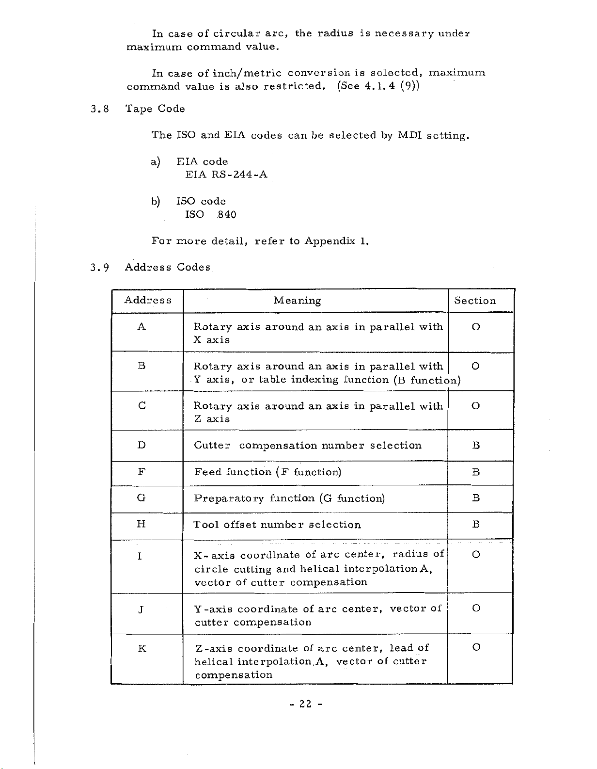
3.9
The
a)
b)
For
Address
Address
A
B
c
ISO
EIA
EIA
ISO
ISO
more
Codes
Rotary
X
Rotary
Y
Rotary
Z
EIA
and
code
RS-244-A
code
.840
detail,
axis
axis,
axis
axis
axis
or
axis
codes
refer
around
around
table
around
can
to
Appendix
Meaning
indexing
be
an
an
an
selected
axis
axis
function
axis
1.
in
in
in
by
parallel
parallel
parallel
MDI
(B
function)
setting.
with
with
with
Section
O
O
O
G
H
D
I
F
J
K
Cutter
Feed
compensation
function
Preparatory
Tool
X-axis
circle
Y
helical
offset
coordinate
cutting
vector
-axis
cutter
Z-axis
compensation
of
coordinate
compensation
coordinate
interpolation.
function
number
cutter
(F
function)
selection
of
helical
and
compensation
of
of
22
-
number
(G
arc
arc
arc
A,
-
selection
function)
center,
interpolation
center,
center,
vector
of
radius
vector
lead
cutter
of
A,
of
of
B
B
B
B
O
O
O
Page 27
Address
Wteaning
Section
L
M
N
O
canned
of
of
helical
EIA
code
block
shift
of
number
value
cycle
copy
function)
(M
programming
of
end
and
or
sub
(S
function)
number
number
N
starting
sequence
canned
in
number
function
(in
of
number
copy
function
(T
Frequency
Repeat
Miscellaneous
Sequence
Same
P
Dwell,
copy
control
Q
Step
and
with
and
distance
sequence
programming
R
S
T
Point
of
Spindle
Tool
R
programming
-speed
function
cycle,
interpolation
function)
only)
sub
canned
block
tape
tape
of
in
repeating
of
cycle
times
O
B
B
B
O
O
O
O
0
U
V
W
X X
Y
Z Z
Section:
Note)
Additional
Additional
Additional
axis
Y
axis
axis
B
indicates
6
indicates
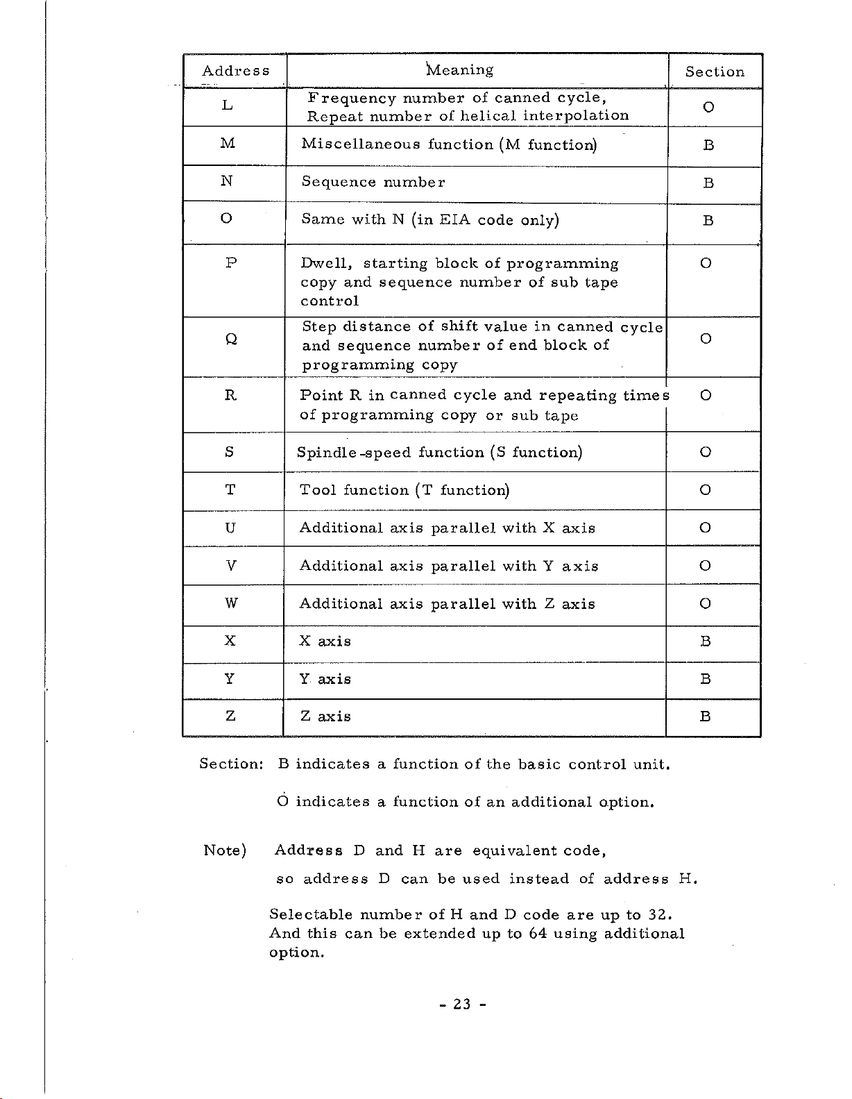
Address
so
address
Selectable
And
this
option.
D
number
can
axis
axis
axis
a
function
function
a
and
D
be
parallel
parallel
parallel
H
are
can
be
of
extended
of
of
equivalent
used
H
and
with
with
with
the
an
D
up
X
Y
Z
basic
additional
instead
code
to
64
using
axis
axis
axis
control
code,
of
are
unit.
option.
address
to
up
additional
O
O
O
B
B
B
H.
32.
23
-
Page 28
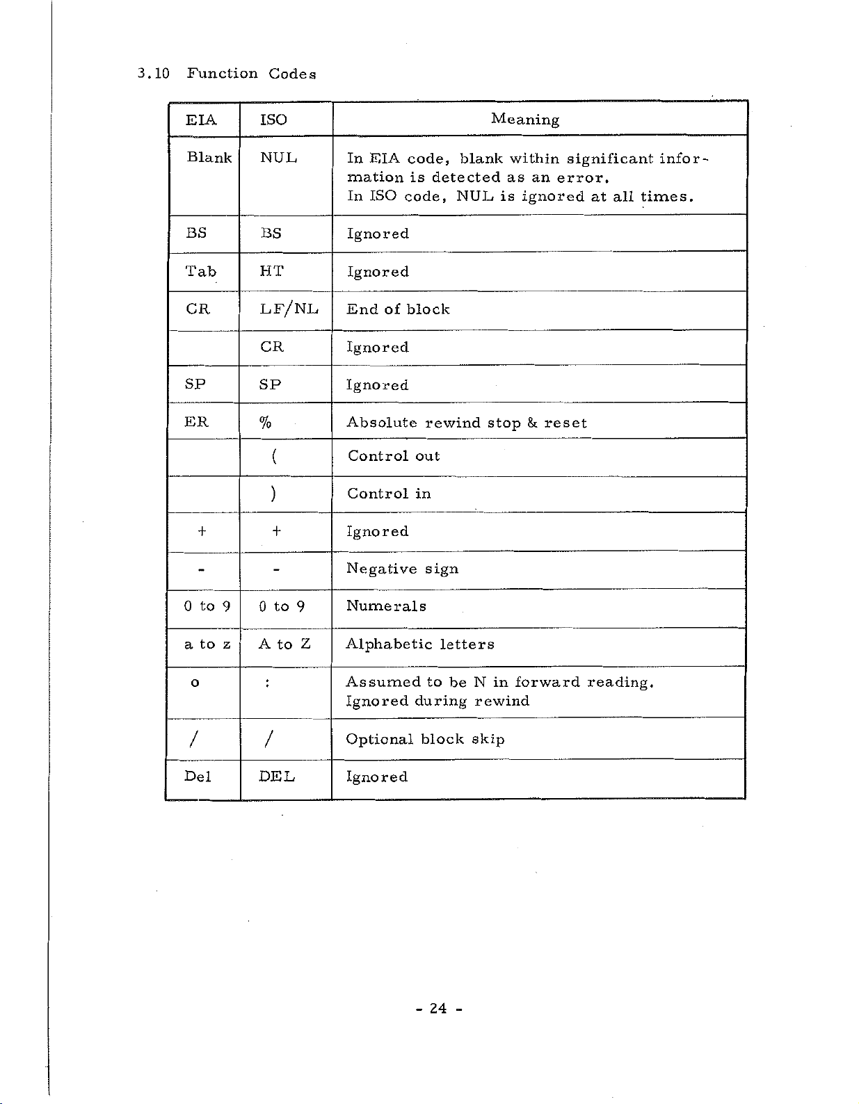
3.10
Function
Codes
EIA
Blank
BS
Tab
CR
SP
ER
ISO
NUL
BS
HT
LF/NL
CR
SP
%
(
)
EIA
In
mation
ISO
In
Ignored
Ignored
of
End
Ignored
Ignored
Absolute
Control
Control
code,
is
code,
block
out
in
blank
detected
NUL
rewind
Meaning
within
as
is
ignored
stop
fk
an
reset
significant
error.
at
all
infor¬
times.
0
a
o
/
Del
to
to
++
to
0
9
z
9
A
to
Z
/
DEL
Ignored
Negative
Numerals
Alphabetic
Assumed
Ignored
Optional
Ignored
sign
letters
to
during
block
be
in
N
rewind
skip
forward
reading.
24
-
Page 29
(1)
Label
Skip
Function
(2)
(3)
a
tape
If
mation
information
The
EOB
mation.
The
display
a)
b)
Control
All
parenthesis
formed.
reset,
Stop
has
Absolute
The
this
reset.
reader
code
label
the
the
information
and
no
code
code
is
read
is
ignored
has
And
skip
panel
power
equipment
Out/in
code
When
Control
Reset
effects
Rewind
means
read
is
this
If
with
reels,
in
until
been
this
at
function
lights
is
(Only
including
is
the
In
is
this
in
Stop
an
within
code
with
until
read,
up
turned
is
ignored,
power
is
effected.
not
absolute
is
the
the
the
reset
a
state
becomes
when
on,
reset
at
EOB
used
section.
and
Significant
read
tape
Label
End
is
Label
in
ISO
is
in
Reset
during
feed
of
command
called
on
or
a
mode
code)
between
and
turned
However
this
rewind
is
Skip
Block
the
lamp
skip
and
other
TH
and
on,
section.
stop,
Information,
manual
stopped
Function
code
is
Tape
the
left
or
(EOB)
read
Significant
turns
lamp
than
parenthesis
TV
checks
when
Absolute
And
in
and
operation
unconditionally.
on,
after
off.
on
MDI
the
Rewind
EOB
addition,
means
it
all
infor¬
is
read.
first
the
Infor¬
the
mode.
and
are
not
equipment
code
when
a
the
tape
on
right
per¬
is
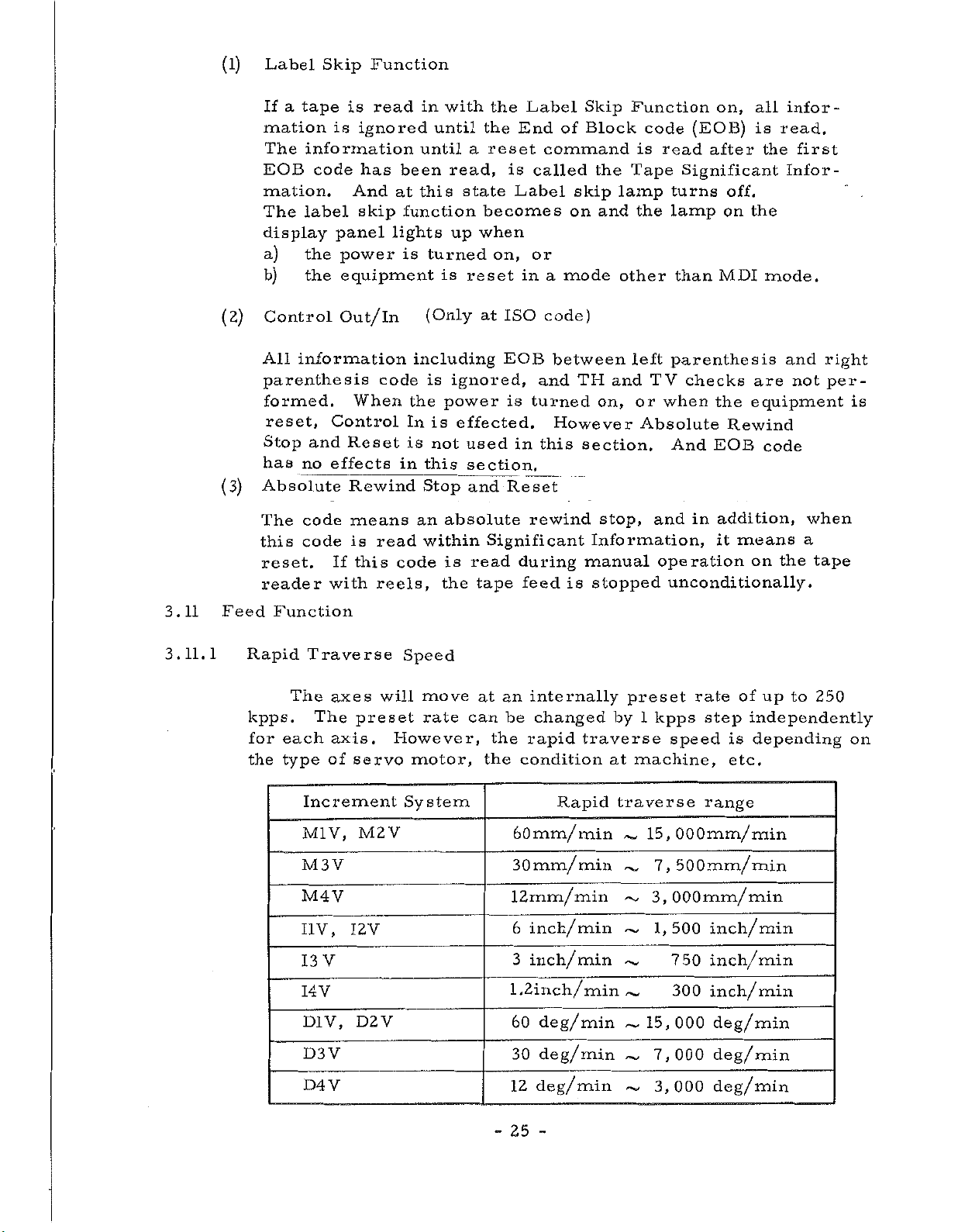
3.11
3.11.1
Feed
Function
Rapid
kpps.
for
the
Traverse
The
The
each
type
Increment
M1V,
M3
M4V
I1V,
V
13
I4V
D1V,
D3V
D4V
axes
axis.
of
V
preset
servo
M2
I2V
D2V
Speed
will
However,
motor,
System
V
move
rate
an
the
the
internally
be
rapid
condition
at
can
60mm/
30mm/
12mm/min
6
inch/min
3
inch/min
1.2inch/minÿ,
60
30
12
changed
traverse
Rapid
min
min
deg/min
deg/min
deg/min
preset
by
1
at
machine,
traverse
15,
~~
~
~
~~
15,
~
~
~
up
of
independently
is
depending
etc.
kpps
speed
rate
step
range
OOOmm/min
7,
500mm/
3,
OOOmm/min
1,500
750
300
000
7,000
3,000
min
inch/min
inch/min
inch/min
deg/min
deg/min
deg/min
to
250
on
-
25
-
Page 30
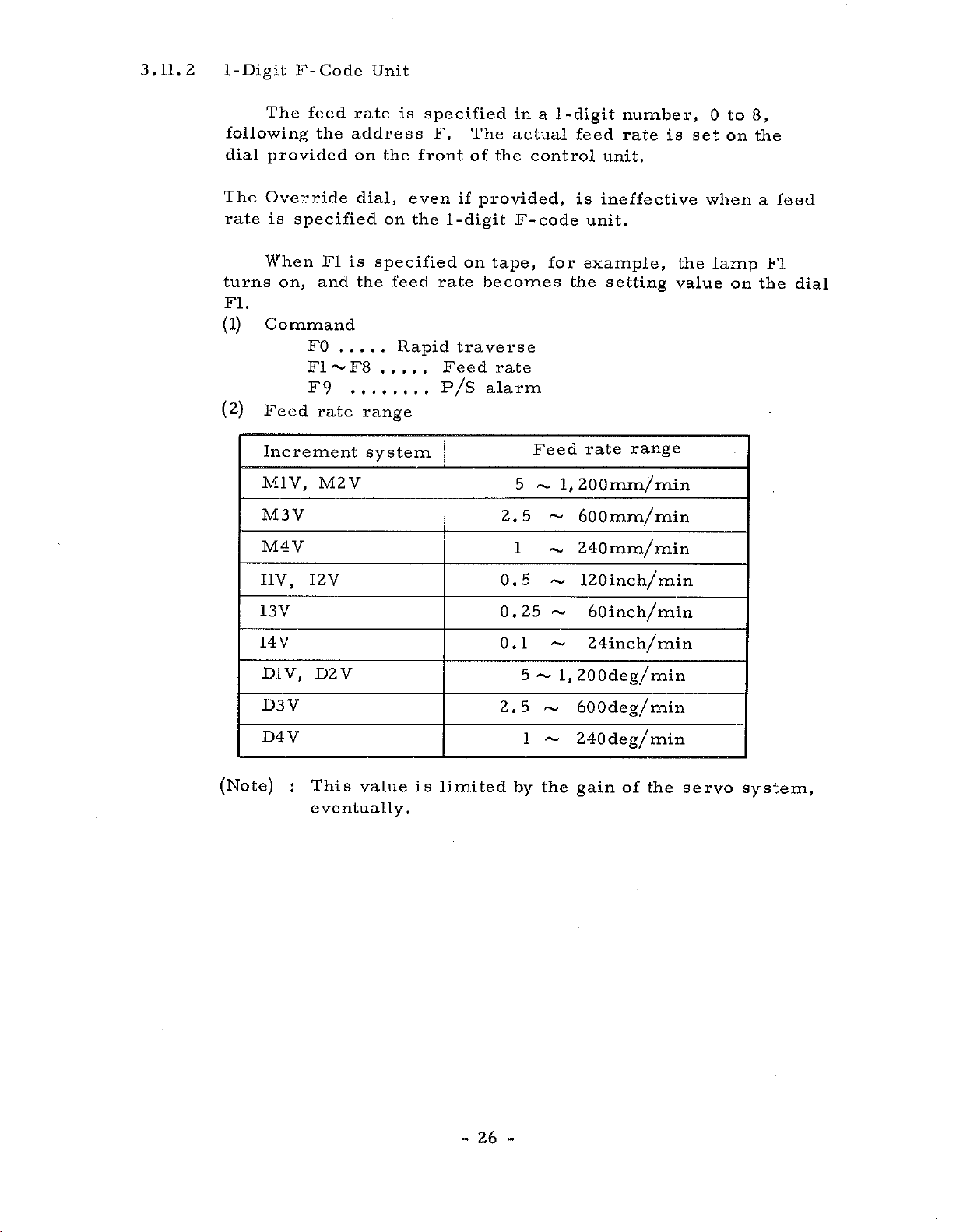
3.11.2
1-Digit
The
following
provided
dial
F-Code
feed
the
Unit
rate
address
on
the
is
specified
front
F.
The
of
the
in
a
actual
control
-digit
1
feed
number,
rate
unit.
to
8,
0
is
set
on
the
The
rate
turns
FI.
(l)
(2)
Override
is
specified
When
on,
and
Command
FO
F1~F8
F9
Feed
Increment
M1V,
M3V
M4Y
I1V,
I3V
I4V
D1Y,
D3V
D4V
I2V
D2V
FI
rate
M2V
dial,
is
the
even
on
specified
feed
Rapid
.....
the
if
1
-digit
rate
traverse
Feed
on
P/S
range
system
provided,
F-code
tape,
becomes
rate
alarm
5
2.5
1
0.5
0.25
0.1
5
2.5
1
is
ineffective
unit.
for
example,
the
setting
Feed
~
~
rate
1,
200mm/min
~
600mm/
240mm/
~
120inch/min
~
~
60inch/min
~
24inch/min
l,200deg/min
600deg/min
~
240deg/min
~
range
min
min
the
value
when
lamp
on
a
FI
the
feed
dial
(Note)
This
:
eventually.
value
is
limited
-
26
-
by
the
gain
of
the
servo
system,
Page 31

3.11.
4
3
-Digit
F-Code
Unit
min
that
actual
of
the
and
issued
feed
The
or
inch/min
can
be
feed
motor
is
usually
the
by
Increment
system
M1V
M2V
V
M3
M4V
I
V
1
V
I
2
V
3
I
V
I
4
rate
specified
rate,
used,
lower
machine
Table
is
specified
following
is
however,
or
the
than
tool
3.11.1
Format
as
F40
F41
F41
F41
F41
F32
F32
F32
address
in
is
time
these
builder
F
directly
Table
limited
constant,
values.
code
F.
3.11.1.
as
range
F
code
FOll
FOll
1
FO'l
FO'l
I
FOjl
F|01~
-4—
F'01~,F
i
F]01~F
a
in
The
the
by
etc.
Refer
to
what
range
F3600
~
F3600I0
~
F
~
F
~
F
~
F
number
range
The
type
of
to
the
1800|0
7
20b
600
3
360100
1
180
of
upper
and
the
the
upper
—
00
code
---
00
72|
in
feed
servo
rates
limit
load
condition
description
limit
mm/
of
the
system,
is,
of
0
on
the
In
a
CEL
ignored
4
-digit
in
order
D
1
D2
D3
D4
Override
An
to
200%
operator's
With
Fixed
switch
F-code
V
V
V
V
to
the
dial
Cycle
on
(assumed
to
distinguish
can
this
panel.
at
(tapping
the
to
should
F40
F41
F41
F41
applied
be
feed
operator's
100%,
be
100%).
be
from
rate
in
on
the
the
feed
cycle
commanded
G84),
panel
1-digit
FOll
FO'l
F01!
F01
~
+
~
~
.
1
~
L
increments
FEED
rate
is
and
ON,
at
more
F-code.
F
360*0
F3600i0
F1800I0
720,0
F
Decimal
in
or
with
*
mm/
deg/min
of
RATE
same
the
the
however,
than
point
min.,
10%
OVERRIDE
OVERRIDE
2-digit
expressed
inch/min
in
the
as
specified.
the
range
dial
CAN¬
Override
is
27
-
-
Page 32

Example
F
F450
code
3.11.
1
Correspondence
Rates
Increment
V
Ml
M2V~M4V
V
II
V
12
~
14
system
V
between
the
Feed
450
mm/min
45
.
0
45
0
.
4.50
F
Codes
rate
mm/
inch/
inch/
min
min
min
and
Feed
Notes
Note
on
the
The
1:
mixedly,
a
(Examples)
Feed
1-,
number
F3
F23
F3545
DIV
D2V
function
and
and
code
~
4
o
o
D4V
-Digit
are
F-Code
identified
following
With
the
Without
the
effected.
The
the
1-Digit
4
-Digit
4-Digit
address
1-Digit
F-Code
the
1-Digit
F-Code
Increment
45
45
Feed
the
by
F-Code
0
deg
deg/min
.
0
functions
number
F.
F-Code
Feed
F-Code
Feed
/min
system
Feed
can
of
Feed
(F3)
Feed
(3
mm/min)
is
effected.
be
digits
option,
is
effected.
MIV
used
of
option,
is
Note
2:
Feed
FO
F1-F8
4-digit
F
code
-
rate
is
GOO
RT
RT
RT
as
follows
,
1
GO
G81
~G89
28
-
by
G73,
RT
Cutting
F-code
Cutting
F
-code
RT:
G
code
G76
feed
feedrate
Rapid
command.
GO2,G03
G12-G15,
S
Alarm
P/
rate
by
by
Traverse
G39
l-digit
4-digit
Page 33

Note
Acceleration
3:
by
move
ration
the
command.
speed-up
and
Deceleration
and
circuit
deceleration
near
Refer
to
for
are
the
Section
details.
effected
start
3.
and
Automatic
18
automatically
end
points
Accele¬
of
a
becomes
F
code
F
rate
code
is
of
each
the
modal,
is
axis
specified
once
specified.
is
controlled
feed
specified,
rate.
it
so
is
the
that
effective
tangent
until
Note
Note
4:
5:
The
speed
The
another
feed
I
29
-
-
Page 34

3.12
Preparatory
Function
(G
Function)
Table
G
code
GOO
G01
GO
GO
3
4
GO
G12
G13
G14
G15
G17
G18
G19
G25
G27
G28
G29
G38
G39
G40
G41
G42
G43
G44
G45
G46
G47
G48
G49
G73
G7
G80
G81
G82
G83
G84
G85
G86
G87
G88
G89
3,12.1
2
lists
Group
A
A
A
A
>1'
*
A
A
B
B
B
*
*
*
*
*
*
C
C
C
*
*
>:<
>:<
*
D
6
D
D
D
D
D
D
D
D
D
D
D
G
codes
Table
3.12.1
Positioning
Linear
Circular
Circular
Dwell
Circle
Circle
Herical
Herical
XY
plane
ZX
plane
plane
YZ
Programming
Zero
Automatic
Return
Cutter
Corner
Cutter
Cutter
Cutter
Tool
Tool
Tool
Tool
Tool
Tool
Tool
Canned
Canned
Canned
Canned
Canned
Canned
Canned
Canned
Canned
Canned
Canned
Canned
Function
interpolation
interpolation
interpolation
cutting
cutting
interpolation
interpolation
selection
selection
selection
return
zero
to
zero
compensation
offset
compensation
compensation
compensation
offset
offset
offset
offset
offset
offset
offset
B
B
increase
decrease
double
double
B
cycle
cycle
cycle
cycle
cycle
cycle
cycle
cycle
cycle
cycle
cycle
cycle
List
CW
CCW
copy
check
return
+
-
cancel
#10
#11
cancel
#1
#2
#3
#4
#5
#6
#7
#8
#9
G
of
return
left
direction
direction
increase
decrease
codes
CW
CCW
CW
CCW
start
vector
cancel
right
side
side
point
set
Section
B
B
O
O
B
O
O
O
O
O
O
O
O
O
O
O
O
O
O
O
O
O
O
B
B
B
B
O
O
O
O
O
O
O
O
O
O
O
O
O
30
-
-
Page 35

G
code
Group
F
unction
Section
G90
G91
G92
G98
G99
Notes
(1)
(2)
(3)
G
on
Generally
same
the
in
When
mixedly,
The
Table
function,
Furthermore,
reset.
the
G
code
3.12.1,
E
E
*
F
F
code
speaking,
block.
G
codes
G
the
having
is
is
but
Absolute
Incremental
Programming
point
Return
cycle
Return
cycle
the
belonging
code
it
specified
the
modal,
canceled
not
is
alphabetic
programming
programming
to
initial
R
to
canceled
G
and
by
point
code
to
once
another
of
can
the
later
absolute
level
level
be
same
is
letter
specified,
G
even
zero
in
canned
in
canned
specified
group
effective.
Column
in
code
the
if
repeatedly
are
maintains
the
of
control
B
B
B
0
O
specified
Group
same
unit
in
its
group.
is
(4)
(5)
(6)
(7)
The
effective
is
Column
In
means
G
code's
When
canned
And
G
code.
G
code
Additional
the
cycle
the
having
only
Section
state
A
-group's
mode,
A-group's
for
option.
Power
at
Group
A
B
C
D
E
F
the
*
the
of
Table
G
the
G-code
mark
block
3.12.1,
ON
G
unassigned
code
canned
suffers
is
which
in
as
are
code
GOO
G40
G80
G91
G98
is
commanded
cycle
not
B
no
modal,
it
means
follows.
is
canceled
effects
specified.
is
during
by
and
Basic,
its
function
and
the
automaticaly
canned
the
O
•
cycle's
31
-
Page 36

3.12.1
Positioning
command
The
(GOO)
GOO
GOO
specifies
two
Any
axes
3
Since
the
tool
rapid
the
to
the
a
-
a
positioning
axes
simultaneous
rapid
the
does
path
traverse
description
are
traverse
fi
atfi,r
(
to
controlled
control
necessarily
not
speed
issued
*
r
performed.
be
is
is
by
:
X,Y,
a
at
provided.
is
made
independently
set
machine
the
(Basic)
>:<
(Option)
Z,U,V,W,A,
time.
for
each
become
With
tool
an
axis
straight.
for
builder
B
additional
independently,
or
each
C)
Also,
axis,
for
that
option,
since
refer
value.
32
-
-
Page 37

Example
3.12.1
Program
example
for
positioning
and
tool
path
100
(l)
(2)
Increment
Rapid
Incremental
Program
Note
;
Increment
Rapid
Traverse
system
traverse
250
This
system
M1V
feed
command
X
GOO
command
I1V
feed
rate
25000
is
rate
X
axis
axis
Y
Y
-10000
incremental.
X
axis
axis
Y
Z
axis
9,
600mm/min
9,600mm/min
*
axis
Y
-
ipm
960
ipm
960
ipm
480
X-axis
Notes
(1)
Program
Z-axis
on
Since
point
thereon.
rotary
the
that
machine
the
GOO
positioning
generally
the
to
Particularly
axis
work
4
end
are
tool.
X
the
point,
specified
does
4000
0j
not
Y
Y
4
tool
4000
-axis
T
is
path
make
when
interfere
sure
a
simultaneously,
Z
4000
not
plurality
with
straight
that
*
the
X-axis
there
of
be
tool
from
is
axes
no
including
careful
other
or
start
the
obstacle
enough
parts
the
so
of
33
-
-
Page 38

3.12.
2
Linear
The
Interpolation
command
(G01)
G01
G01
Specifies
Any
option,
The
In
controlling
angles,
speed
increment
command
is
converted
as
a
rule),
F
rate
becomes
a
—
a—
linear
two
3
axes
feed
the
becomes
systems,
increments
and
F
=
the
—
ft
ft~r
axes
or
rate
the
feed
into
Fx2
\/
specified
P
—
*
8
F—
—
—
interpolation.
4
basic
rate
the
the
the
*
«
,
(
are
axes
is
specified
move
+
,
ft
controlled
specified
three
of
each
including
are
increment
Fy2+Fz2+Fa2
feed
(Basic)
(Option)
8
,
;
r
control
axes
axis
feed
considered
is
controlled
rate.
X,
Y,
at
is
an
in
rate.
rotary
system
Z,
a
time.
provided.
F
(X,
is
controlled
axes,
to
so
U,
code.
Y
and
When
be
for
(of:
V,
equal,
that
W,
As
Z)
move,
the
the
U,V,
A,
an
meeting
so
axes
basic
generalized
B
or
additional
the
that
with
the
least
the
feed
axis
W,
A,
C)
right
at
tangent
different
rate
(X
B
or
axis
feed
C)
Example
The
under
Increment
(1)
Program
Z
-axis
the
3.12.1
path,
following
Y
when
system
G01
-axis
20
programmed
conditions,
M1V
X3000
Y2000
is
Z4000
30
(in
as
»—
The
X-axis
direction
Incremental
follows:
F200
feedrate
commands)
*
this
in
is
200mm/min.
34
-
-
Page 39

(2)
Increment
Program
B-axis
system
G01
D1V
B-9000
{basic
F300
*
axis
M1V)
90
7
The
is
rotary
300
feed
deg/min
rate
1
-
35
-
Page 40

3.12.3
Circular
G02
GO
(GO
G02
(GO
GO
(G03)
The
three
G
code.
XY
ZX
Y
Interpolation
and
X
2
3)
X
3)
Y
2
plane
planes,
(Refer
plane
plane
Z
plane
GO
each
3
on
specify
Y
Z
-
Z
which
to
G17
G18
G19
(G02,
of
which
Section
circular
I
I
J
an
G03)
arc
must
3.12,7
interpolation,
K
K
exists
be
Plane
F
-
F
is
limited
specified
Selection.)
*
*
*
to
the
following
by
the
appropriate
Note
Note
1;
2:
Plane
word
have
When
is
regarded
When
is
regarded
When
is
regarded
When
more
among
or
one
X-Y
2X
GO
(G03)
selection
X,
Y,
not
been
or
or
or
G
three
four
I)
as
J)
as
K)
as
code
(X
(Y
(Z
the
than
address
plane;
—Y—Z—
is
also
Z,
is
J
I,
commanded
(Y
and
X-Y
and
Y-Z
and
Z-X
of
axes
axes
commanded,
J
I
—
and
or
plane.
or
(Z
plane.
(X
or
plane.
plane
address
address
c=i>G0
*
—
selectable
K,
when
after
are
J)
are
K)
are
I)
selection
words
the
2X—
(G03)
the
by
G17,
power
commanded,
commanded,
commanded,
is
words
are
(X,
plane
Y
I
—
—
adress
G18
and
G19
on;
the
the
the
uncommanded
commanded
Y,
I,
J),
only
is
regarded
J
—
*
plane
plane
plane
and
as
G02I
(G03)
G02K
(GO
—
3)
*
—
c=>The
This
-
plane
36
(The
ignored,
is
command
-
information
regarded
is
)
as
ignored.
X-Y
of
Z-axis
plane.
is
Page 41

The
GO
GO
Clockwise
with
respect
negative
the
direction
se
The
2
3
are
rotary
clockwise
counterclockwise
and
XY
to
direction
right-hand
a
in
shown
direction
(CW)
counterclockwise
plane
of
3.12.
Fig.
in
of
the
(ZX
plane,
Z
axis
rectangular
3(a)
is
arc
(CCW)
axis,
(Y
.
defined
employed
plane),
YZ
X
coordinate
axis)
by
here
looking
from
system.
G02
are
and
toward
the
G03.
defined,
positive
Y
2
GO
G17
Fig.
Z,
and
according
the
point
and
J
I,
center
an
Incremental
These
GO
3
3,12.
end
The
is
expressed
coordinate
the
of
K
for
the
K,
or
of
the
are
X
3(a)
point
to
G90
of
arc.
axis
however,
arc
shown
or
the
The
from
value,
in
X"
GO
Clockwise
of
an
an
in
G91,
end
arc
X,
Y
is
a
the
independently
Fig.
GO
2'
G18
is
arc
Absolute
respectively.
point
center
Z,
and
vector
start
3(b).
12.
3.
3
Z
and
counterclockwise
specified
or
is
specified
specified
is
respectively.
component
point,
of
Z
‘
GO
the
by
Incremental
In
incremental
as
seen
by
looking
and
is
always
and
G90
2
address
the
The
G91.
GO
G19
value
from
address
number
toward
3
X,
expression,
the
specified
Y
Y
or
start
J
I,
following
the
in
Center
End
Y
u/
X
point(x,y)
j
/
/
The
The
actual
gent
3.
Fig.
feed
direction
12.
feed
Start
T.
j
Center
3(b)
rate
rate
is
X
point/
is
the
End
u
z/
/
specified
is
controlled
specified
point(z,x)
t
/
t
k
in
feed
37
-
-
an
so
Start
_
.
ii
Center"
F
code.
that
rate.
Z
U/
point/
the
Y
End
/
/
feed
point(y,
/
j
rate
in
z)
Start
the
point
tan¬
Page 42

Example
3.12.3(b)
Specification
in
circular
interpolation
The
Incremental
Absolute
a)
G92
G90
b)
Incremental
100
above
GO
GO
60
40
0
noted
values
programming
X20000
X
3
14000
2
X12000
programming
path
as
can
follows:
Y
Y
10000
Y
50R
120
90
be
4000
6000
OR
6
140
programmed
Increment
Z0
I
6000
-
I
5000
-
20
"
6
in
system
F300
X
Absolute
*
*
>:<
and
M1V
G91
Refer
programming.
(Note)
In
the
circular
polation
GO
GO
to
case
performed
is
3
X-6000
2
X-2000
Section
the
arc
end
drawn
Y
6000
Y
-4000
3,12.14
point
for
according
of
the
1-6000
I
5000
-
for
Absolute
circular
radius
to
F300
command
at
the
*
*
and
start
following
Incremental
is
not
point,
the
conditions.
on
inter¬
38
-
Page 43

E
\
\
\
\
s
Kww\\
In
case
\
\
\
\
\
s
of
X
\
\
\
0
\\W\\
\
\
\
\
\
G02
\
\
\
\
\
\
E
\W\\\
S
E'
,
E
6E'
\
\
\
\
\
s
:
:
E
Start
End
\
z
point
point
\\\\\
E
K
\
\
\
\
\
\
\
In
\\j
case
\
\
\
\
E
0
X
\
\
\
\
of
\
v
\
\\W\
G03
E
s
\
\
\
\
vv.
S
\\
\
\
)—»
\
\
—
\\\\
z
QE
(Example)
(1)
(2)
In
case
shown
tion
value
with
is
distributed
In
case
rant
above
polation
polation
to
the
item
in
toward
point
S
the
in
the
performed
is
of
one
coordinate
the
not
or
figures,
is
is
conditions
(1)
the
.
is
E
end
point
above
of
two
value
by
a
point
end
within
multi
a
performed.
performed
in
are
applied,
end
point
E
is
figures,
up
axes
straight
is
the
item
in
within
the
to
on
of
the
not
oblique
-quadrant
In
in
every
(l).
is
it
the
the
circular
a
point
arc
the
end
line.
within
line
case,
this
quadrant
Unless
done
quadrant
oblique
where
plane
point.
the
as
circular
by
in
interpola¬
coordinate
The
same
shown
inter¬
the
according
the
straight
a
which
as
line
coincides
rest
quad¬
the
in
inter¬
conditions
line
the
S
5
end
-
39
-
E
S
:
Start
E
:
End
point
point
Page 44

3.12.4
Dwell
(GO
4)
permits
time
The
axis
Example
Note
The
specified
address
added),
Increment
M1V
M2
I1V
12
V
1:
command
the
NC
a
3.12.4
V
M4V
~
V
14
~
Since
function
G04
is
GO
command
a
in
can,
U,
:
2.5
System
G04
the
is
specified.
P
4
number
instead
V,
sec
command
effective
W,
of
code
of
A,
dwell
NC
GO
GO
GO
G04
*
next
the
P,
B,
command
4
P250
4
P2500
4
P250
P2500
only
block
following
X,
be
C
not
is
for
a
address
Y,
modal,
block
to
Z,
Max.
be
F
the
in
delayed
P.
or
Command
1048.
1048.
1048.
1048.
Dwell
which
a
57
575
57
575
by
(with
the
the
Valve
sec
ii
1
.
1
40
-
-
Page 45

3.12.
5
Circle
The
Cutting
command
G12
(G13)
I
(G12,
G13)
D
-
-
F
*
cuts
the
machining
as
The
Actual
specify
Starting
along
This
The
X-axis
The
rotary
G12:
G13:
Y
circle
following
command
starting
independently
absolute
direction
Clockwise
Counter
radius
axis
from
radius,
of
cutting.
the
is
point
value
clockwise
circule
a
center
circule.
possible
of
the
of
of
the
(CW)
of
onX-Y.
machining
sign
address
arc
(CCW)
is
decreased
tool
diameter
a
is
circle,
circle
address
of
I's
defined
the
is
dimension
by
by
offset
cutter
always
I.
G12
moves
on
used
is
and
G13.
amount.
and
7
(Example
4
3.12.4)
r
Increment
D
NC
©
//CD®
v
©
/
40mm
=
system:
(Offset
command:
G12
number):
I
4000
©
D05F200*
M1V
5
0
(offset
-
axis
X
amount
7
ool
T
(G12)
(D—
(G13)
©ÿ(D
00)
5
Path
Y
\>/©
axis
V
©
©
-/?)—
¥i
tool
0—
©—
diameter
/
X
©—
—CD
©
axis
©
0
1
41
-
-
Page 46

3.12.6
Herical
Interpolation
A
(G14,
G15),
B
(G02,
G03)
Helical
movement
ronizing
Tool
paths
effective
sional
The
helical
traverse
the
to
ly
(l)
By
plane
large
The
command
G14
(G15)
between
the
become
for
cams
command
commands
Helical
the
and
a
diameter,
I
G14:
G15:
interpolation
two
third
large
axis
spiral-shaped.
-diameter
.
interpolation
of
interpolation
-axis
3
linear
Clockwise
Counter
control
interpolation
etc
K
axes
with
instruction
the
to
the
can
(CW)
clockwise
means
while
the
milling
third
two
of
be
easily
L
circularly
simultaneously
angle
axis
axes
A
circular
a
in
machined.
D
CCW)
(
of
This
and
is
made
which
moving
Z
axis,
interpolating
rotation.
feature
cutting
by
is
moving
in
curved
interpolation
thread
F
synch¬
is
most
-dimen¬
3
adding
cutting
the
linear¬
paths.
in
X-Y
*
of
I
K
L
D
F
Notes
Note
Radius
If
the
And
number
axis.
Lead
Repeat
Tool
If
inside
an
Feed
on
1:
value
the
helical
if
offset
tool
a
offset
rate
the
This
conditions
o
o
(the
value
the
,
the
(sign
direction
number
offset
circle,
a
is
Herical
function
X-Y
axis
Z
value
of
seen
commanded
is
I
interpolation
I
of
helical
is
plus
of
times
of
number
amount
and
made
outside
interpolation
can
.
plane
:
:
:
from
commanded
is
a
begins
interpolation
the
axis,
time
at
Z
(positive
is
positive,
tool
a
if
a
circle.
be
only
Circular
Linear
interpolation
start
by
minus
on
of
point
the
the
by
begins
threding
is
number)
an
offset
performed
interpolation
amount
to
positive
axis.
-X
negative
the
on
negative
offset
as
arc
an
number,
the
+X
to
the
direction.)
in
made
is
negative,
following
center)
positive
42
-
-
Page 47

Note
2:
Set
the
start
point
to
the
position
on
the
+X
axis.
(2)
Note
Note
Note
Note
Helical
Necessary
interpolation
arc
circular
axes
manded
at
.
in
accordance
that
3:
4;
5:
6:
interpolation
The
specify
by
time.
Whether
linearly
The
feed
feed
When
this
axis
screw
The
"K"
The
rate
number
coordinate
relation
must
lead
linear
commands,
G02/G03
interpolation
the
using
with
of
any
interpolated
the
rate
X-Y
repeat
the
cutting
be
range
B
commands
command
traverse
the
absolute
the
X,
depends
designated
plane.
number
be
can
start
of
be
can
between
satisfied
9
K=
K
~7F~r
as
is
l646000p
can
effective
(I,
instruction.
of
each
or
G90/G91
Y,
and
upon
of
set
to
point.
performed
radius
as
follows
be
within
J,
axis,
incremental
command
Z
axes
G17, G18,
F
code
times
integer
"r"
following
Least
(p:
added
K)
is
The
X,
and
is
circularly
is
circular
doesn't
by
And
the
this
by
of
tool
condition.
to
circular
a
360
used
for
and
Y,
are
programming
status
and
become
adjustment
multiple
method.
path
command
degree!
the
Z
com¬
or
G19.
interpolation
integer,
Z-
of
thread
and
lead
increment)
G17
G18
G19
G17
G18
G19
helical
The
feed
that
rate
the
of
the
specified
G02
G03
Arc
movement
in
Arc
movement.
Arc
movement
interpolation
specified
circumferential
circularly
feed
rate.
X
in
the
the
in
the
by
interpolated
-
XY
.
ZX
YZ
.
the
velocity
Y
-
plane
plane
plane
feed
F
43
-
rate
code,
two
-
-
I
Z
with
with
with
—
J
Z
Y
X
becomes
and
-
I
(tangential
axes
J
K
K
—
axis
linear
axis
linear
axis
linear
is
controlled
becomes
F
cutting
the
velocity)
the
—
so
*
Page 48
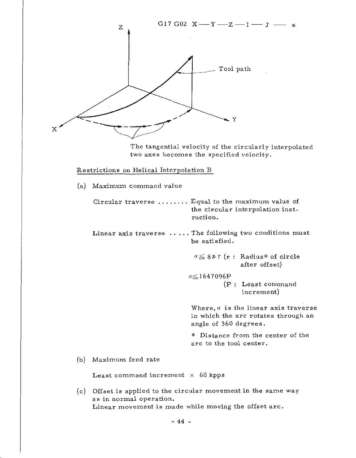
Z
G17G02
X
Y
-
-
-
Z
I
J
-
*
X
Restrictions
(a)
Maximum
Circular
Linear
on
traverse
axis
The
tangential
two
axes
Helical
command
traverse
velocity
becomes
Interpolation
value
the
Equal
circular
the
ruction.
The
satisfied.
be
Tool
of
the
specified
B
to
the
following
path
Y
circularly
velocity.
maximum
interpolation
conditions
two
interpolated
value
of
inst¬
must
(b)
(c)
Maximum
in
command
normal
Least
Offset
as
Linear
feed
is
applied
movement
rate
increment
to
operation.
is
the
made
circular
44
-
a
a<Z
Where,
in
angle
*
arc
x
while
-
<L
87l>
1
647096P
which
of
Distance
to
the
kpps
60
movement
moving
y
a
(r
(P
is
the
360
tool
:
Radius*
after
Least
:
increment)
the
linear
arc
rotates
degrees.
from
center.
in
offset
the
offset)
the
the
of
circle
command
axis
through
center
same
arc.
traverse
of
the
way
an
Page 49

Example
3,12.
6
Example
40
of
helical
/,
y/
interpolation
100
A
z
Tool
P4
P5
path
PI
—
P3
P2
Z
P2
—
X-axis
0
P3
—
•
P4
o
so
Tool
T
ool
ool
T
Increment
s
axi
Z
-
P5
—
—
PI
offset
length
radius
P2
PI
—
number
HOI
D02
system
M1V
(Program
27
male
screw
GOO
G46
G15
GOO
Z
N123
N124
N125
N126
Nl
example)
G45
X
6000
I-
6000K-4000
G46
18000
Tool
screw
machining.
G91
X-6000
H01
offset
machining
Z-10000
D02
*
amount
HOI
*
*
1
L2
*
and
50*
FI
is
programmed
negative
45
-
PI
P2
P3
P4—
P5—
number
P2
—
P3
—
P4
—
P5
P2
positive
by
—PI
is
Approach
Positioning
point
Helical
Positioning
point
Return
for
number
female
of
machining
interpolation
"P5".
to
start
for
to
to
start
center
point
Page 50

3.12.7
Plane
Selection
(G17,
G18,
G19)
3.12.8
The
plane
Note:
Programming
and
times
specifies
executed
block
as
on
Move
G17
the
This
rewinding
once).
The
next
shown
plane
which
XY
plane
ZY
plane
Z
Y
plane
command
,
G18
command
Copy
function
the
command
NC
the
r
times.
to
these
Fig.
in
on
which
offset
and
is
tape,
commands
3.
12.
circular
made,
is
G17
G18
G19
is
G19.
Z
G17
(G25)
that
by
that
N
Thereafter,
NC
G25
-
commands.
8
are
indifferent
For
example
>K
designating
part
P
-
the
of
execution
interpolation
specified
to
plane
a
is
executed
(p)
(q)
Q
—
Sequence
That
Z-axis
part
(r)
-
R
is
is,
made,
is
G17,
by
selection
moves
NC
of
repeatedly
*
Number
continued
the
tape
and
G18
and
of
by
commands
(some¬
to
with
read
to
q
p
is
the
G19.
be
the
in
r-time
N(P);
Advancement
c
r
<
r
Fig.
3.12.8
*
,
....
NC
of
i
These
..
.
NC
ex
Advancement
Copy
tape
tape
cute
(q)
N
commands
advanced,
is
d.
of
*
j
3
NC
are
tape
executed
no
but
by
G25P
.
.
N.
commands
Programming
n
are
46
-
-
Page 51
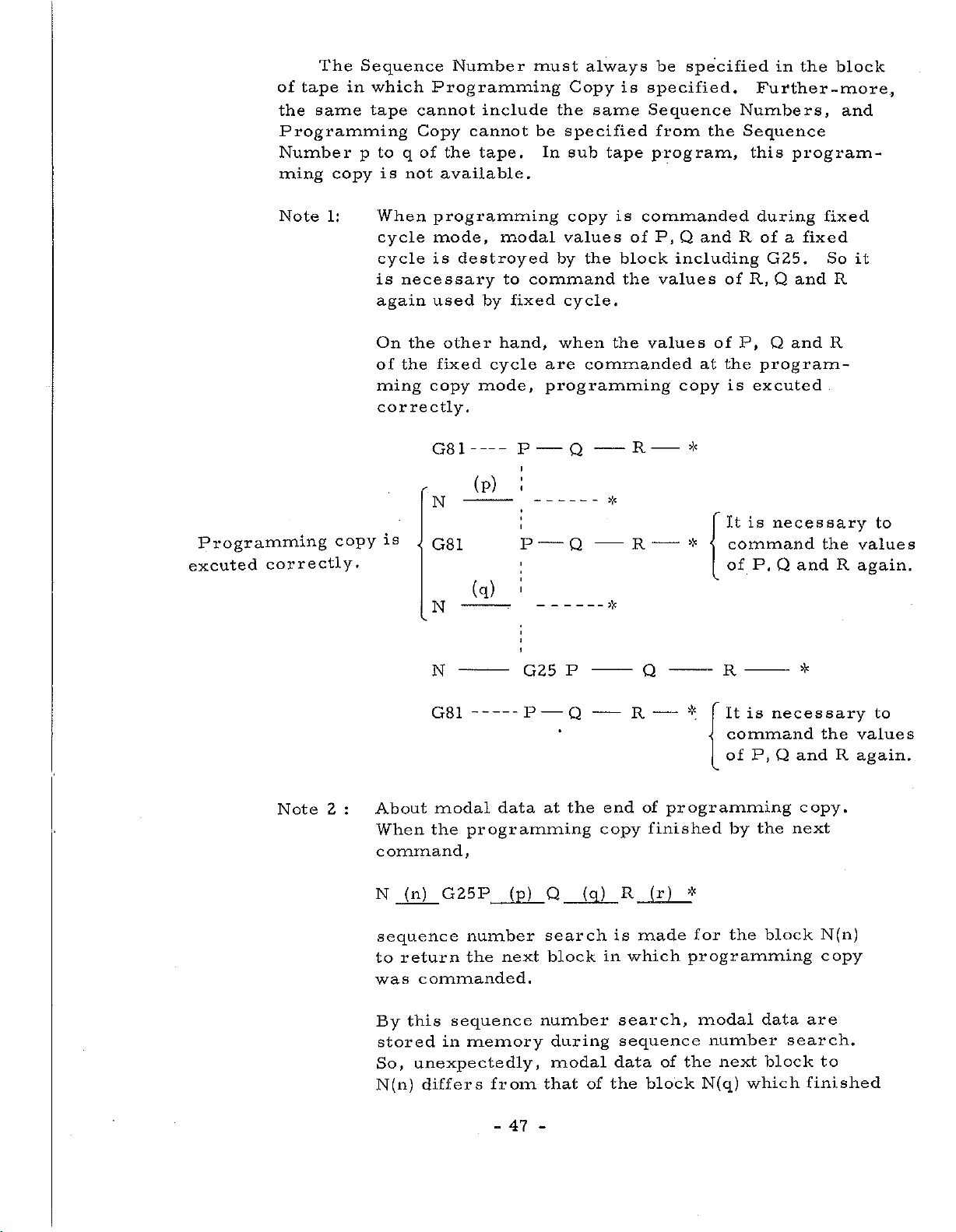
The
of
the
Programming
Number
ming
tape
same
in
copy
Sequence
which
tape
cannot
Copy
to
p
q
is
not
Number
Programming
include
cannot
of
tape.
the
available.
must
be
In
always
Copy
the
same
specified
sub
is
tape
be
specified
specified.
Sequence
from
program,
the
in
Further
Numbers,
Sequence
this
program¬
the
block
-more,
and
Programming
excuted
correctly.
Note
1:
copy
When
cycle
cycle
is
necessary
again
On
the
the
of
ming
correctly.
is
<
programming
mode,
is
used
other
fixed
copy
G81
modal
destroyed
to
by
hand,
cycle
mode,
-
(P)
N
G81
(q)
N
command
fixed
are
programming
__
p
P
'
copy
values
the
by
cycle,
when
commanded
Q
-
-
Q
is
of
block
the
the
R
*
R
*
commanded
Q
P,
and
including
values
values
at
copy
-
*
-
*
R
R,
of
P,
of
the
excuted
is
is
It
command
P,
of
during
of
fixed
a
G25.
Q
and
Q
and
program¬
necessary
Q
and
fixed
So
R
R
the
R
it
to
values
again.
Note
end
copy
R
is
which
in
search,
sequence
data
the
Q
-
R
of
programming
finished
(r)
made
of
block
R
is
It
*
command
P,
of
the
by
*
the
for
programming
modal
number
the
N(q)
data
next
which
*
necessary
Q
and
copy.
next
block
are
search.
block
finished
the
R
N(n)
copy
to
to
values
again.
P
N
G81
G25
P
—
Q
-----
the
(n)
modal
the
G25P
:
About
When
command,
N
2
sequence
return
to
commanded.
was
sequence
this
By
stored
So,
N(n)
in
unexpectedly,
differs
data
programming
number
the
memory
from
(p)
next
at
Q
search
block
number
during
modal
that
(q)
of
47
-
Page 52

the
programming
For
example
at
the
copy.
next
program
N00
N002
i
N005
I
I
i
i
i
NOIO
NO
I
I
I
I
I
after
But
so
G9
GO
i
G40
G90
i
i
G02
G4
i
G25
--
I
I
the
at
I
GOO
I
i
i
!
POO
:*
excution
sequence
the
IQ005R3
N011
%
*
*
*
*
N005,
of
block,
*
*
number
-J
the
i
I
the
—
I
i
i
data
search
data
r~
—
j
Sequence
NOIO
__
i
G91,
is
is
G90,
is
G01,
excuted
G02,
number
search.
G40.
thereafter,
G41.
Note
copy
block
axis
block.
be
programmed
copy
copy
(block
without
(for
(in
the
N
example
(q))
should
data
the
programming
during
programming
programming
commanded.
mode,
Y,
Z
and
at
the
4th
N(q)
next
for
fixed
should
notation,
block
this
block
must
fixed
is
be
cycles
the
By
again
N011
:
3
fixed
If
move
block
About
In
the
the
Dwell)
above
in
the
the
last
cycles
state
command
modal
of
example).
of
the
not
be
cycles
X,
for
commanded
48
-
-
Page 53

3.12.
,
Zero
9
Return
(G27
G28,
G29)
(1)
is
is
a
end
not
the
M30)
Return
a
executed
The
to
Return
is
point
is
been
operation.
zero
Tool
Zero
This
machine
This
G27
beings
Zero
amount
machine
forcedly,
this
Return
Thereafter,
has
tinuing
at
or
one.
compensation
check
function
to
tool
axis
P
move
sequence
the
value
reaches
tool
moves
but
coincides
displayed
if
an
selected,
point,
must
have
compensation
should
(G27)
of
start
such.
as
specified
in
Rapid
specified
up
(lamp
MDI
In
Miscellaneous
a
been
checking
and
at
in
r
Traverse,
is
executed.
machine
the
to
the
with
display,
command
the
order
put
cannot
canceled
be
if
return
the
command
*
in
programmed
the
NC
next
make
to
the
in
a
program
to
and
However,
the
program,
zero
machine
or
the
or
tape
the
function
same
canceled
be
before
the
at
point,
the
Signal
is
machine
G27
specifying
zero
the
end
zero
like).
read
(MOO,
block
at
point.
same
the
and
is
it
point.
point,
Block
in
tool
M01,
the
or
27
G
command,
a
time
movement
not
mode
if
stopped
When
the
con¬
stop
M02
even
for
next
,
tool
so
the
the
Zero
(2)
(3)
ATC
permits
The
Zero
command
Zero
automatically
specified
On
is
executed.
compensation
tool
Return
permits
the
r
point
to
The
positioning
positioning
G28,
in
specified
Return
Return
after
in
,
*
completion
Tool
Zero
command
and
(G28)
G28
performing
and
a
compensation
should
Return
G29
point
further
in
the
a
for
.
r
of
the
start
a
to
be
specified
positioning
,
a
designeted
positioning
Zero
be
canceled
point
performed
in
and
p
P
Return,
cannot
(G29)
the
to
r
axes
be
before
r
from
addresses
be
performed
.
r
to
be
with
next
the
cancelled
G28
the
performed
the
block
command.
zero
,
a
*
dimentions
command
G28,
at
point
to
to
p
and
the
so
49
-
-
Page 54

End
point
D
A
Start
point
Zero
c
8
point
'
Positioning
point
Program
G28X
G29X
_
_
Y
Y
_
_
A
B
to
to
*
C
*
to
C
B
to
D
Y
-axis
Return
Switch).
(Automatic
gramming
point
Example
X-
Positioning
po
End
point
axis
int
D
This
B
positioning
possible
is
The
does
point
to
3,12.9
B
(refer
zero
Tool
point
Change)
not
require
C.
Program
tool
C
SpaoIÿtfO
A
point
path
Zero
*0
.1
B
must
Section
to
C
is
possible.
is
considering
example
point
usually
position
be
a
4,7,12
position
a
Consequently,
the
ATC
for
Tool
at
Increment
A
B
C
point
B
zero
to
to
to
to
change
B
C
B
D
in
ZERO
in
dimension
Zero
is
point
Positioning
Zero
Return
Positioning
C,
system
Return
to
which
RETURN
which
pro¬
from
Return
performed
MlV
start
Zero
ATC
and
Program
G28X-1500
MO
6
*
G29X-3000
The
command
cannot
Note:
I—
be
In
speed,
-30
-415
4
example
Y
4000
Y-6000*
of
coordinate
programmed
G28,
G29
so
a
(In
*
command,
tool
50
-
case
Point
Tool
Point
between
path
-
of
incremental
A
to
change
C
to
system
G28
each
does
B
B
not
C
to
D
to
setting
and
G29
axis
generally
programming)
zero
or
block.
moves
setting
the
at
straight.
rapid
Page 55
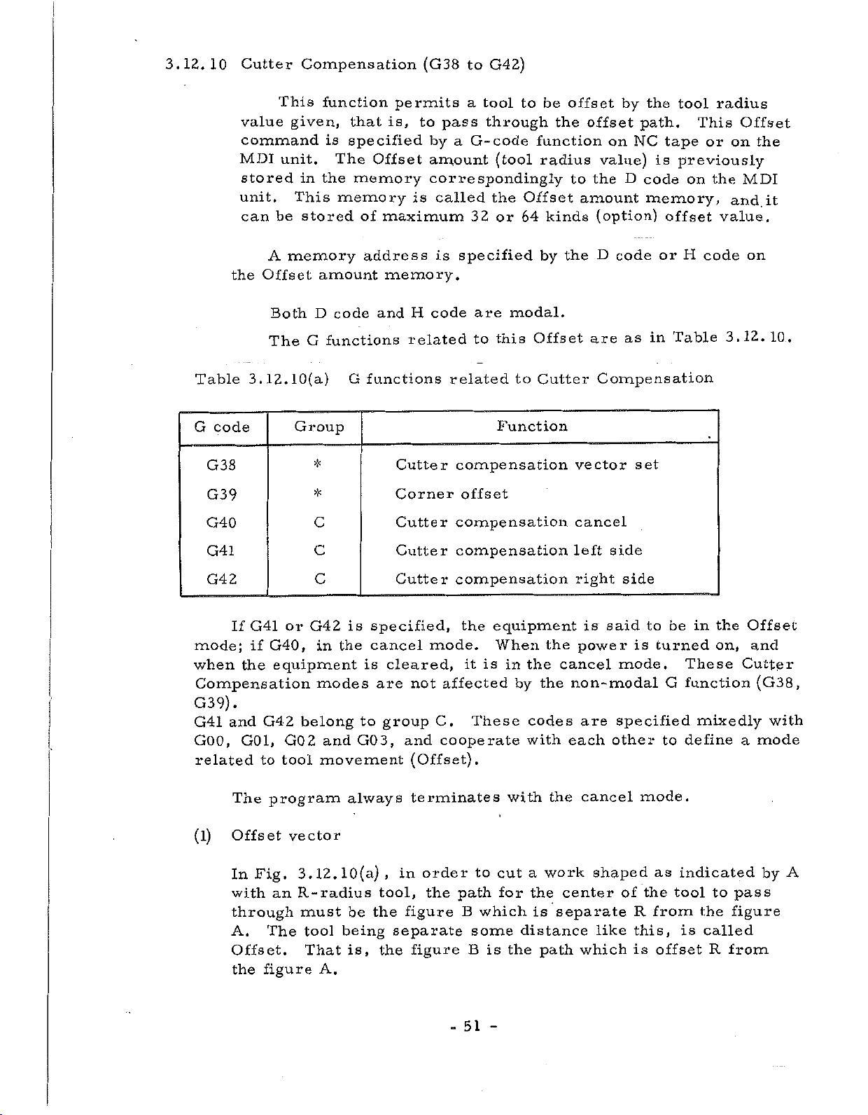
3.12.
10
Cutter
Compensation
(G38
to
G42)
Table
G
code
G38
G39
value
command
MDI
stored
unit.
can
A
Offset
the
Both
The
3.12.10(a)
This
given,
unit.
in
This
stored
be
memory
G
Group
function
is
The
the
memory
amount
D
code
functions
*
*
is,
that
specified
Offset
memory
of
maximum
address
memory.
and
functions
G
permits
to
pass
a
by
amount
correspondingly
is
called
is
code
H
related
related
Cutter
Corner
to
tool
a
through
G-code
(tool
the
Offset
32
or
64
specified
are
modal.
this
to
to
Function
compensation
offset
offset
be
the
function
radius
to
kinds
by
the
Offset
Cutter
by
offset
NC
on
value)
D
the
amount
(option)
D
code
as
are
Compensation
vector
set
the
tool
path.
tape
is
previously
code
memory,
offset
or
Table
in
on
H
This
or
the
code
radius
Offset
on
and
value.
3.12.
the
MDI
it
on
10.
G40
G41
G42
G41
If
mode;
when
Compensation
if
the
G40,
equipment
G39).
G42
and
G41
GOO,
related
(l)
G01,
to
The
Offset
Fig.
In
with
through
The
A.
Offset.
the
figure
program
an
or
belong
2
GO
tool
vector
3.
R-radius
must
tool
That
C
C
C
is
G42
the
in
modes
and
GO
movement
always
10(a)
12.
be
being
is,
A.
Cutter
Cutter
Cutter
specified,
cancel
cleared,
is
are
to
group
3,
,
tool,
the
separate
the
mode.
not
C.
cooperate
and
(Offset).
terminates
order
in
the
figure
figure
compensation
compensation
compensation
the
equipment
When
is
it
in
affected
These
to
cut
for
path
B
which
some
B
is
the
by
codes
with
with
a
the
is
distance
the
the
cancel
the
the
work
center
separate
path
cancel
side
left
right
is
said
power
mode.
non-modal
specified
are
each
other
cancel
shaped
like
which
side
is
of
R
this,
is
to
turned
G
to
mode.
as
the
from
offset
be
in
These
function
mixedly
define
indicated
tool
the
is
called
to
R
the
on,
from
Offset
and
Cutter
(G38,
mode
a
pass
figure
by
with
A
51
-
Page 56

The
specified
control
moment
vector
made
unit,
from
This
and
it
the
vector.
As
with
center
tool
Offset
later)
in
and
a
given
vector
is
shown
the
vector
Offset
unit,
as
cutter
the
direction
is
used
always
very
direction
as
amount,
and
its
is,
in
to
figure.
important
in
Fig.
in
seen
is
a
2
-dimensional
direction
advances.
order
of
a
calculate
belongs
in
3.
12.
which
from
and
this
is
This
know
to
tool,
path
a
to
and
programming
l0(a)
tool
a
work.
the
value
rewritten
Offset
how
etc.,
follows
the
advances,
vector
much
created
offset
vector
is
to
equivalent
kept
from
vector
Offset
by
the
know
is
and
stored
moment
(called
in
the
the
tool
usually
faces
tool
as
the
in
to
is
control
radius
it
behavior
at
toward
in
size
the
to
simply
be
advances,
right
to
of
angles
the
a
R
(2)
/
/
\
\
Fig.
Plane
Offset
tion.
on
vector.
is
mand
mode,
plane
So
again
In
lation
assumption
applies
selection
calculation
On
command
a
not
affected
tape
is
selecting
using
the
sequel,
is
-A
3.12.10(a)
an
An
is
although
not
the
made,
that
also
XY
tape
axis
by
used
made,
the
what
when
and
vector
is
plane
is
coordinate
Offset,
as
offset
the
the
plane
old
offset
vector
an
by
XY
an
another
Offset
made
selected,
used
is.
it
offset
vector
Offset
plane
and
on
plane
a
to
calculate
value
but
the
plane
In
calculation
vector
again,
the
of
created,
is
command,
selected.
is
plane
\
\
vector
for
outside
value
offset
selected.
is
\
i
specified
example,
the
specified
switching
of
of
the
calculation
old
plane.
and
will
B
A
r
L
the
\
»
Offset
the
selected
old
what
be
This
vector
|
plane
in
(X,Y)
to
plane
on
theOffset
in
plane
Offset
discussed
discussion
(I,
or
create
specified
com¬
the
new
remains.
begins
calcu¬
selec¬
J)
a
on
Note
and
code
G18
is
G17,
is
designeted
unassigned,
is
52
-
-
these
selection
G
code
Plane
:
If
by
G17
G19.
selected.
Page 57

(3)
Cutter
(a)
Compensation
Case
The
command
specifies
direction
the
moves
the
old
(I,
point,
is
is
J)
arbitrary.
of
GOO,
a
toward
vector
expressed
and
G01
new
of
the
on
is
significant
left
G41X
vector
(I,
point
the
in
J)
(G41)
-
Y
to
on
the
of
start
Incremental
an
only
be
the
point.
I
created
end
new
as
point,
vector
direction,
a
J
-
at
and
value
D
right
from
-
the
from
*
angles
tool
that
and
the
its
with
center
of
end
amount
Old
vecter
Start
In
case
the
Cutter
Compensation
the
the
equipment
Compensation
D
code.
Start
Old
point
Tool
point
vector
enter
to
amount
Tool
center
Programmed
zero,
is
from
mode.
memory
center
path
(X,
this
the
cancel
this
At
address
Programmed
Y)
path
command
time,
u
(X,Y)
mode
is
New
New
>3
(I.
the
specified
vecter
path
vecter
J)
specifies
into
Cutter
(I.J)
the
by
I,
If
as
(X,
specifies
created.
J
or
Y).
Old
is
K
Tb.at
new
a
vecter
omitted,
is,
vector
53
-
the
Tool
Start
-
(I,
command
at
path
J)
right
center
I
point
is
assumed
G41
angles
Programmed
X
-
with
S
to
New
(X,
be
Y
(X,Y)
Y)
path
the
to
vector
same
>:<
be
Page 58

however,
If,
pendently
at
GOO
the
is
Rapid
specified,
Traverse
each
speed.
axis
moves
inde¬
(b)
Case
of
The
G41
GO
specifies
toward
connecting
center
tool
the
of
new
the
In
old
vector.
old
this
G02,
command
...
(GO
2
a
direction
the
the
vector
vector
case,
3)
new
to
G03
*
X
arc
move
This
is
(I,
vecter
center
on
is,
created
J)
is
-
Y
to
which
in
along
the
arc
however,
specified
I
be
created
an
and
the
arc
the
start
correctly.
as
J—
*
to
arc
advances
arc
end
advancing
point
established
arc
the
the
point,
toward
center.
left
from
on
looking
on
line
a
and
the
of
that
assumption
the
point
the
Old
vector
Start
Tool
point
center
Path
New
(X,Y)
Programmed
J)
vector
path
Old
(hJ)
vector
Start
?
i
i
i
I
i
i
point
New
“Tool
path
Programmed
vector
center
path
54
-
-
Page 59

Example
3.
12.
10(a)
Increment
system
M1V
50.00
f/
—
—
Cutter
(4)
/
/
00
50.
G91
Compensation
/
40.00
4—40.
—
G41
G17
G02
X9657Y-4000
Y
G01
00
—
GO
-4000
56.
1X5000
*
right
Tool
-
\
57R
\
\
\
k
o
—
Y5000F150D06
14000
(Incremental
(G42)
J-4000
center
Programmed
40.00
40.00
O-
—
*
*
command)
path
Y
path
-axis
Unit
:
X-axis
mm
right
advances.
direction
the
(a)
Start
G42,
of
Offset
Case
Programmed
point
contrary
work
a
opposite
method
of
G42X
/
That
GOO,
looking
is,
-
to
to
is
G01
Y
the
that
quite
-
G41,
path
specifies
toward
vector
created
the
I
-
<X,Y)
the
created
same
-
J
Tool
tool
a
direction
by
G41.
as
*
P
/
/
center
by
in
(I,
G42
the
J)
New
path
to
be
in
which
is
Except
case
vector
offset
toward
for
of
to
the
this,
G41.
the
tool
the
Old
vector
55
-
-
Page 60

G42X
(b)
Programmed
Start
Old
the
In
pendently
Case
path
Tool
point
vector'
case
G02,
of
,(X,
New
center
Programmed
GOO,
of
Rapid
the
at
G03
Y)
vector
path
path
however,
Traverse
\
Tool
each
(I.J)
center
axis
speed.
?
Start
point
<*X
New
path
moves
(X,Y)
vector
inde¬
New
vector
Start
/
point
(5)
Old
\
""
vector
Cutter
specifies
old
and
This
Cutter
Compensation
command
The
vector
each
axis
command
Compensation
Old
each
on
vector
axis
the
to
move
specifies
G40X
start
to
cancel
-
move
point
in
the
mode
Old
(G40)
Y
straightly
toward
Rapid
equipment
into
vector
-
Traverse
the
Tool
in
*
the
cancel
center
Tool
/
Programmed
rog
center
GOOorG01
from
end
to
point
in
enter
mode.
path
path
the
GOO
X,
rammed
path
path
point
in
mode.
from
Y)
of
G01
the
the
mode
Start
-
56
point
-
Page 61

When
specified,
direction.
site
only
the
G40
tool
is
*
moves
specified,
old
the
and
vector
X
amount
not
in
is
the
oppo¬
Y
(6)
Corner
permits
radius
(G41)
end
the
arc
the
vector.
end
Old
The
or
point.
offset
G39I
executing
a
at
to
point
from
(I,
vector
Circular
—
corner.
the
right
at
the
is
J)
J
-
Offset
A
(G42)
right
point
expressed
Tool
c
LÿNew
interpolation
in
*
circular
new
looking
angles
the
of
center
vector
G01,
vector
therewith,
old
in
an
(G39)
G02
or
interpolation
is
created
toward
and
vector
Incremental
path
toward
(I,
-o
G03
(I,
j)
J)
the
mode
with
to
from
that
value
the
tool
the
left
moves
of
the
from
tool
along
new
the
only
the
by
and
of
by
This
when
arc
G41
executes
group
this
(I.
command
G41
to
G42,
A
turn
circular
maybe.
is
or
command.
Case
J)
Case
can
or
G42
clockwise
respectively.
The
G41
of
New
__
.
of
G42
be
given
already
has
or
interpolation,
G
function
vector
-J)
in
Offset
been
counterclockwise,
This
specified.
command
whatever
group
of
Tool
Old
mode,
center
vector
is
the
A
remains
that
is
not
G
path
is,
Whether
defined
modal,
function
57
-
Page 62

/
/
/
/
/
Example
/
25.00
3.
35.
12.
oa
10(b)
20.00
Increment
X
N
\
25.00—
\
system
?
~~X
M1V
.00
5
20.50
-axis
Y
L
..
........
X-axis
1-15.00-
Vector
(7)
GO
specifies
the
with.
G41
G17
G91
G39I3500J1500*
X3500Y1500*
G39I2500
X2500Y
G39I
G03X2500Y
rewriting
The
mode
3
right
The
J-2000*
500J-2500
command
new
a
(G42)
tool
—25.00
—
G01X1500Y2500F180D06*
-2000*
*
J
-
created
the
but
(Incremental
D
-
to
(I,
J)
a
-205012500
(G38)
G38
vector
looking
does
not
J500*
I
-
be
to
toward
move,
*
the
at
vector
(I.J)
in
left
right
command)
GOO,
(G41)
angles
is
only
G01,
created.
or
G02
to
there¬
or
in
This
the
command
equipment
can
being
New
58
-
be
still
vector
given
in
only
Cutter
Offset
in
Compensation
mode,
resulting
mode.
Page 63

(8)
General
notes
on
Offset
(a)
(b)
(c)
Specification
The
or
amount
Change
Change
A
Offset
code,
H
first
Compensation
to
pensation
A
cancel
positioning
circular
cancel
Compensation
positioning
circular
be
move
move
change
does
changed.
from
command
mode
interpolation
from
mode
command
interpolation
amount
and
from
not
mode
to
(GOO)
the
(GOO)
of
mode.
the
mode
the
can
need
Offset
the
or
Cutter
or
Offset
memory
be
the
the
at
Cutter
linear
the
at
to
linear
amount
is
specified
Offset
Also,
to
cancel
(G02.
the
(G02,
cancel
once
specified
be
time
Compensation
interpolation
GO
Compensation
time
Offset
interpolation
G03)
memory
specified
anywhere
specified,
mode
of
change
3)
cannot
of
change
cancel
cannot
mode
again,
to
mode
by
to
the
from
mode,
(G01).
be
from
mode,
(G01).
be
the
before
the
the
unless
cutter
the
used.
to
the
used.
D
Cutter
Offset
must
The
the
must
The
code
the
it
Com¬
Offset
Offset
Cutter
has
be
be
Tool
(generally
(d)
center
not
Old
Switch
pensation
The
Offset
from
can
but
or
linear
In
path
straight)/
''J
Programmed
vector
G41
GOO
Fig.
between
right
be
this
G42
3.12.10(b)
Cutter
right
direction
to
left
switch
interpolation
case,
New
(X,Y)
/
X
Y
-
-
Compensation
is
generally
not
through
(GOl),
tool
the
vector
path
G42
*
GOl
*
Switch
switched
through
path
Tool
path
/
/
Old
G41X
of
from
it
only
as
is
center
/
/
/Programmed
vector
Y
—
the
Offset
left
left
Offset
the
in
positioning
Fig.
in
New
X",Y)
1
-
Cutter
and
to
right,
3,
vector
J
—
—
Direction
cancel
12.
(h
path
F
Com¬
or
(GOO)
10(b)
J)
*
>:<
—
mode,
59
-
-
Page 64

(e)
Change
of
the
Offset
amount
Increment
Ml
M2V
M4V
I1V
I2Y
The
changed
the
polation
Tool
center
Programmed'
path
Old
Fig.
system
V
V
14
Offset
in
Offset
(G01)
/
vector
3.12.10(c)
Table
amount
the
mode
/
Offset
only
.
/
s
3.12.10(b)
Maximum
+
+
+_
+
is
changed
cancel
positioning
in
New
>;
Programmed
Change
command
8388.
999
999.
860
838.
99.
9999
vector
Tool
path
Old
of
Tool
6
0
mm
mm
inch
inch
generally
mode,
center
path
vector
Offset
the
length/offset
value
can
but
(GOO)
__
S
/
/
when
be
or
/
amount
the
changed
linear
>
amount
tool
New
is
in
inter¬
vector
(f)
Positive/negative
for
with
versa.
10(d)
tool
is
vise
amount
figure
a
the
if
work,
amount
path
made
versa.
male
be
selected.
Offset
the
If
made
is
replaced
sequently,
of
side
vise
and
Fig.
3.
Offset
the
When
a
amount
and
(b),
cutting
them
the
12.
both
can
each
shows
negative
Offset
is
in
other
center
tool
will
it
is
programmed
is
programmed
Consequently,
female
and
60
-
-
amount
made
which
in
pass
one
(-),
negative
G41's
process
the
is
passing
around
example.
the
shapes,
and
as
tool
and
to
in
the
center
tool
(-),
G42's
sheet.
around
inside
the
Generally
positive
be
(a),
center
same
any
and
path
distribution
are
Con¬
the
thereof,
speaking,
(+).
the
moves
tape
gap
Offset
if
all
out¬
as
permits
between
in
Page 65

7
(9)
Tool
(a)
Fig.
For
interpolation)
cannot
to
with
Examples
Example
(D
center
3.12.10(d)
a
cut
an
provide
3.12.10(c)
cornered
made
be
inside
the
appropriate
smooth
of
the
©
20
path
Tool
amount
in
use
center
figure
general,
negative
corner
radius
cutting.
Offset
of
path
positive
(involved
the
(-)
of
©
or
Offset
to
cornered
a
must
(b)
by
negative
in
cut
be
Tool
making
corner
amount
the
inserted
center
the
inside.
figure,
Offset
circular
naturally
In
an
there
path
order
arc
to
©
©
40
//
/
20
@1
Increment
40
Zero
W
point
systermMlV
40R
20
—
61
-
20R
-
d>
Y
-axis
X-axis
Page 66

Q
G91G17G00G41J6000D08
(D08
corresponding
the
is
MDI
an
unit,
Offset
)
*
number,
thereto
is
and
specified
tool
a
radius
previously
value
on
2
G18
3
G17
A
3
6
7
8.
9,
0)
G18
.1
G17
Example
©
©
G01Z-2500F
Y6000F250
20
-
6000
J20
*
00Y
*
G3
914000
X4000Y2000
G39I4000
G02X4000Y
X
IX-
GO
G00Z2500
G40Y-2000M0
3.12.10(d).
©
&/////
'
/
/
/
30
y
/
//////
100
*
*
00
*
*
-4000J-4000
-20001-2000
*
2
*
'//////
50
s
s
/
/s/
*
*
©
Y
-axis
/
/
/
y
©
X-axis
Zero
Jo
point
©
©
©
I
8
®/
0
20
Increment
G91G17
G18
G17
7
9
1
G
8
1
D
G
®.
—I
system
GOO
(DO
corresponding
the
7
is
6
MDI
G01Z-2500F100
Y3000F250
G39I5000
X5000
G39J-3000
Y-3000
G39I-5000
X-5000
G00Z2500
G40X
G4
-
©
:
1X200
Offset
an
unit.
2000Y
MIV
0Y
)
*
*
*
*
*
*
*
2000
number,
thereto
*
*
2000M02
-
J3000D0
is
specified
*
and
6
*
tool
Unit:mm
radius
previously
value
on
-
62
-
Page 67

3.12.11
Tool
Offset
B
Example
the
by
amount.
amount.
12.
3.
CD
(D
CD
©
O
Tool
command
The
G43
G44
offset
offset
specifies
specifies
Tool
for
amounts
offset
11(a)
G92Z0
G90G00Z1000
G43G01Z2000H01F-ÿ
G00Z3000
0
*
*
+1000
0
of
0
that
that
*
Z
G43
axis
B
-
+2100
or
is
tool
tool
is
(Tool
G44.
selected
is
moved
is
moved
cancelled
Programming
Absolute
Tool
*
100)
+
G
0
length
by
by
offset
offset)
D
toward
toward
or
H
G49.
of
programming
direction
+
+3100
o
can
code.
direction
+
direction
-
Absolute
performed
be
(Offset
by
by
Zero
offset
offset
Point.
amount:
Example
Example
3.12.11(b)
0
(D
(D
0
G92Z0*
G90G01Z1000F200*
G44Z2000H01*
GOO
©
G
,
1
2
.1
3
Tool
G92
G90
G43
path
©
©
©
1
Z
+1000
(c)
Z
GOO
Z
o-
3000
o
0
*
Z
1000
*
©
2000
H01
©
*
*
o
+1100
+1900
o
(Offset
©
Programming
Absolute
Tool
+100)
offset
0
amount:
+2000
+2900
of
Absolute
programming
direction
-
+100)
Zero
(Offset
Point
amount:
-
63
-
Page 68

{Note
is
The
until
offset
cancel
l)
data
by
is
other
modal,
offset
and
command.
this
data
effective
Example
Example
(Note
3.12.11(d)
0
0
0
0
©
@
G92
G91
G43G01Z1000H01F200*
Tool
Tool
path
o
3.
12.
G92
G91
G43G01Z-1000H01F200*
path
2)
ZO
Z1000
11(e)
Z0
Z
This
programmed
direction.
+
*
*
(D
*
2000
*
or
1000
+
o
-
direction
end
Incremental
(Offset
point
©
(Offset
of
tool
and
amount:
offset
ineffective
programming
+2100
amount
is
+100)
+100)
:
effective
to
movement
to
Example
o-
(Note
3.
0
I
I
Tool
(Note
o
CD
+
offset
The
3)
end
point
(f)
1
1
12.
Z0
G92
G90
G43G01Z2000H01F200*
G43G00
G44G01Z4000H03F200*
path
0
*
Z1000
Z3000H02*
+1000
*
0
o
new
4)
The
old
the
considering
offset
offset
1100
is
in
o
effective
case
+2100
o
data
new
of
data
offset
(D
at
incremental
(Offset
Off
set
(
(Offset
®
is
commanded
is
canceled
data
+2000
absolute
amount:
amount:
amount:
+3200
o
is
value
mode.
+100)
+200)
+300)
0
in
for
and
performed.
of
offset
the
programmed
+3700
o
mode,
positioning
64
-
-
Page 69

Example
3.12.11(g)
®
(2)
(3)
®
G92
G90
G43
ZO
ZO
Z1000
G01
HO
2
*
Z2000
*
HOI
*
F200
(Offset
*
(Offset
amount
amount
+100)
:
:
+200)
H02
is
ignored.
Example
Tool
path
o-
(Note
3.12.11(h)
<£)
(2)
(D
@
Tool
o
o
G92
G90
G43
G49
path
5)
o
+100
ZO
GOO
G01
GOO
©
The
As
the
effective
>:<
Z1000
Z2000
Z0*
©
G
1000
+
o
code
code
H
.
*
H01
+1000
©
of
G43
is
F200
©
(D
modal,
(D
and
*
+2100
o
G44
the
(Offset
+2100
not
is
predetermined
modal.
amount
+100)
:
H
code
is
(Note
(Note
(Note
(Note
6)
7)
8)
9)
Tool
These
in
When
G43,
displayed
G43,
mode
G43,
and
offset
fixed
G19
commands
cycle
Z-axis
the
and
G44
on
and
G44
during
G44
and
mode.
B
is
mode.
G49
DPL
G49
the
G49
-
canceled
G43,
of
command
codes,
unit,
can
offset
cannot
65
-
be
mode
by
G44
is
the
used
be
G49
and
not
P/S
of
used
code.
G49
programmed
alarm
in
only
and
G41
in
the
can
the
(No
G17
G42.
G18
not
35)
be
after
used
is
Page 70

3.12.12
Tool
Offset
A
(G45
to
G48)
By
specifying
specified
setting
codes
G
code
on
in
and
Table
G45
G46
G47
G48
These
tool
for
pensation
radius
(G4-5toG48)
G45
excuted.
to
G48
the
their
of
tape,
NC
Offset
functions.
3.12.12
Tool
Tool
Tool
Tool
G
function
compensation
G41
being
can't
G45
offset
offset
offset
offset
and
excuted.
be
to
etc.
amount
Tool
Function
are
G42
done
G48,
can
memory.
Offset
increase
decrease
double
double
used
of
can't
Conversely,
during
the
movement
increased
be
and
increase
decrease
for
simple
a
done
be
the
Table
G
tool
during
function
distance
or
3.12.12
Codes
length
drawing.
tool
(G41
of
decreased
shows
compensation
Tool
and
function
G42)
these
compensation
the
by
the
com¬
being
axis
a
G
or
of
These
which
in
These
others,
memory,
memory,
By
By
G
they
offset
remain
setting
work
a
setting
tool
a
Offset
amount
codes
are
specified,
amounts,
unchanged
the
shape
the
path
Tool
are
tool
tool
becomes
pat
<
modal,
not
once
until
radius
becomes
wearing
''///./////
T-
/
the
/
/
/
and
selected
other
value
the
programing
value
programing
Work
programmed
tool
effective
offset
the
in
in
shape
path
by
amounts
offset
the
the
offset
as
only
D,
path.
H
amount
path.
amount
for
codes
are
block
a
and
selected.
66
-
-
Page 71

which
Tool
the
path
tool
increases
advances.
or
decreases
to
the
direction
toward
decreases
end
the
the
by
At
block
the
point
time
to
the
of
including
of
direction
the
last
absolute
block
G45
command,
toward
to
G48.
to
the
which
position
tool
the
path
tool
which
increases
advances
is
or
from
commanded
67
-
-
Page 72

(1)
Command
and
Offset
Move
command
data
Start
(iii)
(b)
(a)
point
Move
Offset
G46
G45
(i)
«—
End
command
Move
Offset
(increase
command
amount
End
point
&-o
1234
+
+567
----
-*
-f—
801
1
(decrease
567
-12
34
567
+•
Start
34
12
__
--
point
-
*
by
1234-
801
1
command
amount
point
__
o-
567
_
—
command
B-
—
a
by
(ii)
Start
point
offset
a
Offset
Actual
offset
amount
movement
amount
Move
Offset
I-
66
1234
7-1
-
*
—
Move
(iv)
Offset
*567
-1
amount
amount
memory)
command
amount
End
point
567-
—
!
command-1234
amount
End
point
—
4)
3
2
J667
memory;
+
-
-
1234
567
567
Start
point
The
setting
reversed.
Move
(i)
Offset
actual
Start
movement
the
in
command
amount
point
switch
+5
End
with
+1234
67
point
__
7-
6
5
„
1234
67
6
-A
amount
G45,
becomes
the
ii)
sign
to
equivalent
which
of
iv)
are
to
is
omitted.
a
-
68
-
Page 73

(c)
G47
(i)
command
Move
(increase
command
+
1234
by
double
(ii)
offset
Move
amount
command
memory)
+
1234
(d)
(iii)
G48
The
offset
which
Offset
Start
Move
Offset
End
command
actual
point
—1234
_
-
point
246
amount
reversed.
is
amount
-1480
command
amount
1234
—1480
(decrease
movement
memory
-
-
+
-
4
Start
123
End
---o
246
1234
123
amount
with
point
by
point
double
becomes
G47
,
(iv)
with
Offset
Start
offset
;
point
.
—988-4
Move
Offset
End
246
4
1234
|_988_
amount
equivalent
the
sign
amount
End
"7246
1234
command
amount
point
_
—
memory)
to
of
-
.
Start
a
123
point
-
-
1234
123
point
(i)
In
offset
as
In
that
zero
In
no
Move
Offset
a
command
amount,
zero
case
case
of
movement
movement
of
movement,
command
amount
Start
point,
in
incremental
incremental
absolute
—1234
988H
-
which
in
movement
the
amount
command.
mode
to
(iv)
are
1234
+
123
+
246
a
mode.
mode
is
End
move
(G91),
equal
(G90),
(ii)
point
is
amount
to
it
to
be
it
offset
can't
is
can
omitted.
made
specified
be
amount
be
made;
by
made
only
by
a
69
-
-
Page 74

Offset
amount
+
01234
Offset
No.
01
Programming
Equivalent
command
command
G45X0
X
1234*
D01*
G46.X0
X
-1234*
D01*
G45X-0
X-1234*
D01*
G46X-0
X
1234*
DON'
70
-
Page 75

(2)
Notes
on
Tool
Offset
(a)
Start
point
(b)
case
In
control
axes.
Case
Tool
If
little
G45
to
move
G45
of
Move
Offset
Programmed
a
command
amount
Actual
tool
Offset
depth
G48
are
command,
command
path
effected
is
of
cut
specified
Tool
Programmed
path
tool
for
is
generated.
for
Offset
X10000
+2000,
G45
both
G01
axes,
2-axis
a
is
effected
Y
5000
Offset
X100000
Offset
too
at
No.
much
-a-time
for
02
Y5000
amount
or
both
D02*
Actual
shape
machined
much
Too
depth
of
cut
a
Y-axis
Desired
shape
X-axis
machined
G01X
G45X
—
—
Y
—
F
Y.
*
-
—
*
D
—
*
71
-
Page 76

Desired
shape
machine
0
*
D—
F—
X—
5
4
G
1
G
Too
depth
(c)
(d)
of
Tool
Circular
one
Cutter
one
In
in
a
cut
-quarter
-quarter
case
the
little
direction.
Tool
movement
•'
Offset
Actual
shape
-axis
Y
can
Interpolation
or
Compensation
or
the
command
figure
\
X-axis
be
three-quarter
three-quarter
below,
Start
/
machined
effected
(GO
is
possible
is
reversed
move
a
point
G
by
2,
GO
is
X
5
Y
4
G48
to
G45
3)
only
command.
arc
in
only
command.
arc
to
due
made
in
Programmed
End
*
commands
the
in
the
the
the
point
case
That
case
decrease
reverse
command
>:<
of
of
for
a
is,
a
as
(Example)
G46X250*
Offset
(e)
G45
(G41
If
mode,
or
(f)
G45
In
manded
(incremental
amount
G48
to
and
G42).
want
you
command
G42.
G48
to
this
case,
after
can't
to
are
+370
This
use
ignored
fixed
the
-
Offset
amount
command)
used
be
becomes
(G45
both
code
G40
during
cycle
G80
has
72
-
Equivalent
j
during
(P/S)
G48)
to
after
and
fixed
mode
(G8I
commanded.
tool
X
to
-120*
alarm.
and
that
cycle
command
compensation
{G41
command
mode
G89)
should
or
G42)
(G81
mode
G41
be
to
com¬
G89).
Page 77

Example
Actual
reached
end
3.12.12
pointX,
(a)
Offset
Programmed
G45G03X-7000Y
Increment
amount
system
Actual
+3000,
command
7000
M1V
tool
path
Offset
1-7000
No.
DO
01
1
*
Offset
amount
Example
o
o
o
r-
O'
Actual
center
3.12.12(b)
-o
\
Programm
end
point
O
Programmed
Center
Cutter
polation
S
\
\
\
\
\
\
00
70.
Compensation
Programmed
\
\
\
Start
G46G00X
G45G01Y
G45G0
G01X
3X
X
point
in
-
-
tool
Circular
Y
-
-
F
Y
>:<
D
>:<
I—
-
path
Inter¬
*
J—
*
Programmed
tool
path
H
!
I
Actual
-
—
tool
path
L.
73
-
-
Page 78

Example
3.12.
12
(c)
Program
example
using
Tool
Offset
Zero
point
40
40
50
©
/•
80
©
@
Tool
i
--
J
Tool
radius
—
—
©
50
diameter:
compensation
@
I
I
*1
40
20
I
I
I
—
"*@3
OR
©
30R
/
¥
/
©
=_—30
•©
30
----
I
©
I
I
/
Y
-axis
X-axis
10)
if
12)
13)
14)
3)
5,
Q
7,
8)
9)
Offset
Increment
Program
G46
G91
G47
G01
Y
4000
G48
X4000
Y
-4000
G45
X3000
G45
GO
G45
G01
G46
XO
G46
GO
G45
G01
X
G47
G47
G46
-12000
Y
-8000
GOO
No.
GOO
X5000
*
*
3
X3000
Y
*
2
X-3000
Y0
X
01
system
example
X8000
*
*
2000
*
*
*
-8000
F120
Y3000
*
Y3000
Y-5000
Offset
M1V
Y5000D01
*
J3000
J3000
*
amount
*
*
*
+1000
74
-
Page 79

Tool
length
compensation
Actual
position
Programmed
position
Zero
vLU
A
Drilling
point
!
I
Compensation
amount
of
holes
dV
#1,
120
20
3P
3,0
r
35
30
#2
and
O
18
I
#3.
-
!
h
#1
\
.-#2
I
i
1
--
\
30
#3
JO.
z
-
50
-
-
T
i
1
8
T
T
I
L
“1
I
T
I
22
Offset
Increment
Program
G91
CD
(D
G45
G01
CD
GO
©
GOO
©
X3000
©
G01
©
GOO
X5000Y3000
G01
%
GO
0
G45
©
X
O
example
GOO
Z
Z
4
P200
Z2100
Z
Z4100
Z
4
P200
GOO
-20000
No.
X12000
-3200
-2100
Y
-5000
-4100
-2500
02
system
F100
*
*
*
*
*
*
Z5700
Y
-6000
H02
*
Y8000
*
*
*
*
*
Offset
M1V
-
*
75
amount
Dwell
Dwell
-
at
at
=
hole
hole
+400
bottom
bottom
for
for
sec,
2
2
sec.
Page 80

3.12.13
Canned
turned
The
Cycles
following
on,
the
(G73,
state
G76,
Canned
is
of
G80
Cycles
G80.
to
G89)
are
available.
When
power
is
G
G73
G76
G80
G81
G82
G83
G84
code
Drilling
direc.)
(-Z
Intermittent
feed
Feed
Feed
Feed
Inter
mittet
feed
Feed
Table
Operation
hole
botton
Oriented
spindle
Dwell
Spindle
reverse
3.
at
stop
13
12.
Retraction
Z
(
+
Rapid
Rapid
Rapid
Rapid
Rapid
Canned
direction)
traverse
traverse
traverse
traverse
traverse
Feed
Cycles
High
drilling
Fine
(For
Group
Drilling
Drilling
boring)
Peck
Tapping
Usage
speed
boring
fixed
Cancel
drilling)
drilling
cycle
only)
cycle
cycle
cycle
peck
cycle
cycle
B
(spot
(counter
cycle
G85
G86
G87
G88
G89
(Note
(Note
1)
2)
Feed
Feed
Feed
Feed
Feed
Canned
Independently
are
Canned
M
The
G87
in
cycle
used.
cycle
code
different
mode.
Spindle
Spindle
Dwell,
spindle
Dwell
A
B
signals
operations
stop
stop
stop
signals
for
Manual
Rapid
or
Manual
for
spindle
are
Feed
Feed
operation
traverse
operation
Feed
spindle
reverse
performed
reverse
and
for
Boring
Boring
Boring
Back
Boring
Boring
spindle
Canned
and
cycle
cycle
cycle,
boring
cycle
cycle
spindle
stop
cycle
cycle
are
stop
A
used.
and
B
76
-
-
Page 81
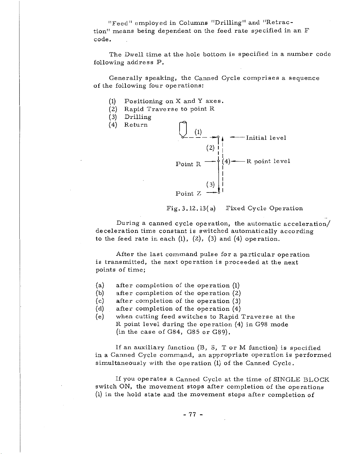
"Feed"
tion"
code.
following
means
The
employed
Dwell
address
being
time
in
dependent
the
at
P.
Columns
on
hole
"Drilling"
feed
the
bottom
rate
is
specified
"Retrac¬
and
specified
in
in
number
a
an
F
code
Generally
the
following
of
(1)
(2)
(3)
(4)
During
deceleration
the
feed
to
speaking,
four
Positioning
Rapid
Drilling
Return
Traverse
a
time
rate
canned
constant
in
each
the
operations:
X
on
and
to
point
Q
Point
Point
Fig.
3.
cycle
(l),
12.
is
Canned
Y
Cycle
axes.
R
(1)
I!
i
I
(2)
(3)
--
(3)
(4)—
i
I
Fixed
and
—
R
---
Z
13(a)
operation,
switched
(2),
comprises
-
“*
Initial
R
-
the
automatically
(4)
point
Cycle
automatic
operation.
a
sequence
level
level
Operation
acceleration/
according
After
transmitted,
is
of
after
after
after
after
when
R
(in
If
If
ON,
the
time;
point
the
an
you
hold
points
(a)
(b)
(c)
(d)
(e)
Canned
a
in
simultaneously
switch
(l)
in
the
last
the
completion
completion
completion
completion
cutting
level
case
auxiliary
Cycle
with
operates
movement
the
state
command
next
of
of
of
of
feed
of
command,
during
G84,
function
the
a
and
switches
operation
Canned
the
operation
the
operation
the
operation
the
operation
the
operation
the
G85
(B,
an
stops
movement
77
-
pulse
is
to
operation
or
G89).
S,
appropriate
(l)
Cycle
after
-
for
a
proceeded
(l)
(2)
(3)
(4)
Rapid
(4)
T
or
of
the
the
at
completion
stops
particular
Traverse
in
G98
M
function)
operation
Canned
time
after
operation
the
at
at
mode
Cycle.
of
SINGLE
of
the
completion
next
the
specified
is
is
operations
performed
BLOCK
of
Page 82

the
operation
command,
L>
the
in
(4)
completion
hold
of
(4)
the
state
the
the
in
movement
operation
up
stopped
to
stops
(L-l)
(4)
state.
times
in
after
the
But
completion
and
the
stopped
in
the
movement
state
cycle
of
at
including
the
operation
stops
the
Lth
after
time.
three
code,
G
(
1)
(2)
(
3)
(Note)
or
G91
These
modes,
Data
Return
Drilling
Data
specified.
as
format
The
Z-axis
cancel
is
Canned
each
shown
point
mode
initial
given
below.
level
at
mode
as
Cycle
of
lebel
the
shown
operations,
which
time
into
is
L
means
of
the
in
specified
G90
G91
G98
G99
G7
3
G7
6
G80
G81
G89
the
changing
canned
Fig.
be
to
Absolute
Incremental
Initial
R
See
absolute
cycle
in
point
Table
the
more
a
level
fixed
3.12.13(b),
particular
level
3.12.13
value
mode.
depending
strict,
of
cycle
come
modal
on
in
G90
Fig.
By
point
specified.
R,
G90
Z
G91
Q
1
0
I
I
Point
Point
return
R
-----
Z
3.12.13(b)
up
or
This
R
*
I
I
.U
operation,
to
the
shown
is
Z
Absolute
initial
whether
level,
in
Fig.
78
-
Point
Point
and
Incremental
tool
a
depends
3.12.13(c)
—
is
<?
I
—
I
I
R
Z
only
on
l
I
L
programming
returned
G98
.
or
R
Z
G99
to
Page 83

the
of
a
Once
initial
combination
a
level
Q
drilling
G98
--
operation
becomes
of
G90
.
!
Initial
level
the
and
is
same
G91.
performed
as
the
Q
in
G99
G
99
<f
i
level,
R
point
--
—
/level
*
mode,
R
point
be
since
careful
Fig.
Data
G73,G76,
command
a
G73
G76
G81-G89
Specifies
X:
Specifies
Y:
Z
:
Specifies
P
Specifies
:
Q
Specifies
:
and
(This
3.
related
modal
(G98
VG99
'
sift
12.
is
13
G81~
permits
value.,
)
/
a
a
a
a
a
value
always
c)
drilling
Initial
(
to
G89.G98
X
Y-
--
hole
hole
Dwell
depth
hole
in
position
position
bottom
time
of
G76
given
data
the
Z
—
in
cut
or
in
level
operation
and
to
L
-
(Absolute
(Absolute
position
the
at
each
(fixed
G87
an
Incremental
R
and
specified
constitute.'
G99
stored
be
P
—
—
(Absolute
hole
bottom
time
cycle
point
Q
or
or
in
level
in
R
—
Incremental)
Incremental)
or
position.
G73
B)
value.)
subsequent
‘one
block.
the
control
F
—
—
Incremental).
or
G83
mode.
*
.
.
mode,
to
unit
these
This
as
R
F
L.
G
This
or
:
Specifies
Specifies
:
Specifies
:
An
code
mode
reset.
R
a
a
feed
the
actual
(G81to89)
drilling
is
cancelled
point
rate
number
giving
lebel
feed.
in
of
operation
a
drilling
G80,
by
79
-
(Absolute
repetitions
is
initiated
a
or
-
mode
different
Incremental)
or
of
the
by
hole
and
same
specifying
position
G
code
cycle.
of
a
data.
group
A,
Page 84

Among
the
in
Example
the
canned
.
12
3
.
address
cycle,
1
3
.
(a)
code
P,
X,
Q,
R
Y,
and
Z,
Q,
R,
F
P,
F
are
modal.
and
used
L
G90G81G99X
Except
R
point
That
direction
do
mode
R
ON
OFF
is,
not
.
point
move
The
According
G80X
is
necessary
a
drilling
toward
tool
and
—
X
G87
for
Z
correctly.
offset
to
initial
Designated
Shifted
Y
-
Y
Y
(fixed
larger
operation
point
commands
state
the
point
value
from
in
value
by
Z
-
*
*
cycle
positive
must
of
G87
manual
R
-
B),
value
be
point.
R
are
ineffective
"MANUAL
G88
and
by
programming.
feed.
F
-
Drills.
Does
the
the
made
Otherwise
mode
tool
absolute
not
to
the
become
Drills
drill,
move
that
in
value
negative
G7
canned
*
than
at
ABSOLUTE"
.
but
.
Z
of
3
follows.
causes
of
-point.
G83
and
cycle
switch",
80
-
-
Page 85

(l)
G7
3
(High
speed
peck
drilling
cycle)
a
q
q.
q-
Return
(2)
i
l
d=
d-
G7
G73
d
I
."7
k
v
dimension
1mm
in
0.1
(Fine
6
6
G7
(G99)
I
1
(M1V~
(I1V
boring
(G99)
Point
Point
~
R
Z
M4V)
14
V
cycle)
(G98)
G73
Q—
l
qT
q.
q.
)
G76
I
s
--+ÿ
-
(G98)
1
Rapid
Feed
Initial
point
Point
traverse
Z
Oriented
Spindle
position
Stop
XI
s
is
preset
value
Shift
Shift
1
q
H
J4
oct>l
\
is
Point
I
l
Point
Oriented
stop
Tool
amount
(designated
amount
parameter
by
modal
and
R
Z
spindle
Shifted
is
address
by
speified
is
used
tool
setting
for
by
XI
Q)
positive
(
+X,
depth
q.
--
Ji=>|
Shift
>=>
-X,
for
of
value.
+Y
cut
Initial
Point
Oriented
stop.
tool
Shift
or
-Y
G73
in
point
Z
spindle
direction
).
This
and
G83.
-
81
-
Page 86

(3)
(Canned
G80
This
G89),
performed.
and
cycle
command
subsequently
Also,
cancel)
cancels
causes
point
R
(Canned
a
and
ordinary
Z
are
Cycle(G73,
operations
canceled.
G76,
to
be
G81
to
(4)
(5)
G81
G82
(Drilling
G81
Q
(Drilling
cycle,
(G99)
I
I
cycle,
G82(G99)
spot
Point
jPoint
i
counter
drilling)
R
Z
Q
boring)
G81
G82(G98)
(G98)
l
point
rapid
cutting
i
l
Point
traverse
feed
--
Z
Q
This
tool
moves
(specified
command
up
after
P
a
in
*1
i
i
Point
!
I
t
Point
,1
®
functions
Dwell
code).
Dwell
R
Z
is
82
-
same
the
performed
-
Q
as
at
G81
the
*”?
i
(P)
except
hole
Jlnitial
point
IPoint
Dwell
that
bottom
Z
the
Page 87

(6)
G83
(Peck
G83
drilling
(G99)
cycle)
G83
(G98)
Q
In
X
G83
is
programmed.
is
and
Rapid
inch
ahead
cutting
?
I
I
---
q
q
q
case,
this
_
y
always
Traverse
of
is
made
111!!!
_
expressed
the
in
Point
—Point
the
_
Z
Q
represents
switches
position
the
R
Z
command
_
Q
in
to
second
R
-
an
cutting
where
Q
F
-
a
depth
Incremental
feed
the
immediately
cutting
i
---
q
q
q
o
Point
o
i
6
•-Point
z
*
time,
one
or
preceding
and
of
cut
at
after.
at
value.
one
each
mm
tenth
(7)
G84
Q
hole
(Note)
(
Tapping
G84
This
bottom,
During
(G99)
*1
“-ÿSpindle
command
rate
cycle)
Spindle
/normal
revolution
Point
Point
reversion
and
a
tapping
Override
R
Z
specifies
tapping
by
are
the
cycle
G84,
ignored.
_____
(G98)
G84
Point
Spindle
reversior
and
point
at
Feed
Z
the
0
spindle
to
the
be
performed.
Feed
I
(
to
Hold
Spindle
l
1
1
normal
revolution
reverse
-
83
-
Page 88

(8)
G8
(boring
5
G85
cycle)
(G99)
G85
(G98)
(9)
the
G86
0
Q
i
I
This
spindle
(boring
G86
command
does
cycle)
(G99)
—
,
\
jPoint
Point
not
Sp
start
f
Point
I
l
IPoint
Spindle
R
Z
functions
reverse
indie
R
Z
stop
the
at
Q.
same
the
hole
G86
G84
as
bottom,
(G98)
Spindle
i
i
I
I
I
I
h
Point
|
I
,
except
Initial
I
Point
point
Z
that
start
point
Z
stop
the
T
raverse.
This
spindle
command
stops
function
at
the
-
84
hole
-
the
bottom,
same
as
and
G81
returns
except
in
that
Rapid
Page 89

/
(10)
G87
(boring
cycle/back
boring
cycle)
CYCLE
A
B
Q.
Point
Point
_
This
used.
CY
stop..
manually
can
tool
cycle
CLE
A
be
is
(G99)
G87
-“"f
A
Spindle
start
*
Spindle
st
should
(boring
state
a
by
op
out
R
Z
hold
Consequently,
made,
drawn
switch
but
not
cycle)
is
it
of
be
provided
this
at
manual
to
is
safe
hole.
the
Point
Point
Point
(ÿSS)
at
time,
finally
to
(G98)
G87
no,
Spindle
start
---
)
\
V
9*=$'
£i
tool
,
Any
make
Spindle
stop
a?
start
bottom
i
I
Spindle
can
manual
a
Z
Jl®
Z
R
Spindle
:
Oriented
hole
the
the
mode
be
state
Stop
after
spindle
moved
operation
which
in
-*ÿ
rapid
-*ÿ
cutting
cz£>
the
traverse
feed
feed
shift
the
in
the
in
CYCLE
When
The
command.
restarting
tape
next
B
following
(1)
(2)
(3)
(4)
(5)
(6)
(7)
(8)
(9)
(10)
(11)
mode,
block
it
of
(back
Oriented
Shift
Positioning
Return
Spindle
Boring
Oriented
Shift
Return
Return
Spindle
of
of
maching,
restarted
is
N
tape
C
boring
operations
spindle
opposite
to
shift
of
start
to
point
spindle
opposite
to
initial
to
positioning
start
.
cycle)
stop
tool
point
amount.
(CW).
Z.
stop.
tool
point.
(
CW)
if
are
tip
R.
tip
point.
.
operation
the
according
performed
after
positioning
direction,
direction.
is
the
to
automaticaly
initiated
commands
of
X
and
by
Y
this
axes.
Note)
Shift
value
and
direction
85
-
G76
are
same
as
mode.
-
Page 90

(11)
G88
(boring.
cycle)
the
(12)
(G99)
G88
Q
Spindle
?
I
start
---
This
spindle
G89
Z
(boring
Point
/
*
I
\
®
command
stops
(G99)
G89
Dwell
Spindle
Stop
functions
the
at
cycle)
hole
the
bottom
Q
Point
same
after
G88
*
—
—
Z
G87
as
Dwell.
G89
(G98)
—
6.
_
©
(G98)
Spindle
Dwell
Spindle
-
Stop
(fixed
start
cycle
A)
Dwell
same
the
the
at
Q
use
return
the
—
This
If
In
command
is
made
drilling
cycle,
of
the
point
beginning.
i
I
—
i
Point
Dwell
R
Sr-
functions
the
at
at
the
address
commands
is
hole
equal
number
L.
G98
initial
bottom.
intervals
of
repetitions
or,
lebel
the
G99
Q
same
is
or
as
to
be
can
including
R
point
I
'
i
'
<g
r-
G85
repeated
be
specified
L
lebel
Dwell
except
the
in
designation,
respectively
that
by
The
The
maximum
word
of
is
value
is
L
only
86
-
Li
effective
-
8388607.
programmed
in
block.
Page 91

repetition
functions
output
The
only
designation
number
are
specified
once
of
at
of
positioning
in
same
the
repetition
same
the
time
and
with
number
drilling.
block,
positioning.
designate
If
these
S
M,
function
the
and
T
are
Example
Current
3.12.13(a)
position
First
The
command
X
-
mental
fied
Y
in
specifies
values
Absolute
machining
G98G81X
G98*
the
values,
_Y_
the
case
G81X
(in
position
Y
-
first
of
drilling
_
Z
_R_
Z
machining
G91).
_
is
/
Last
R
L5F
this
If
repeated
maching
_
L5F
-
*
position
command
in
*
the
position
or
in
Incre-
is
same
speci¬
position.
87
-
-
Page 92

Example
3.12.13(b)
Programming
station
and
using
Canned
Cutter
Cycle
Compen-
Zero
Y
point
o
in
rq
o
o
3
o
3-
o
1
o
o
H
#1
G
#2
<>-
#3
c
e
#7
#8
0
0
#11
#12
#13
0
€0
#10
#9
#6
<>
#5
0
—
—
#4
e
0
x
400
150—*
Z50-
•250
450—
Z
Tool
compensation
numbe
length
r
10mm
20mmf
95mm0(5Omm
The
to
Hll=
H15=
H31=
95mm0
T31
pi
Boring
Drilling
Drilling
Boring
Vi
i
Note:
bar
H31
6.
#1
#7-10
i
I
X
o
LO
oo
o
m
o
o
LO
o
s
Drill
position
retraction
Til
l
10mm
Fill
&
of
o
CJN
Drill
—
#11-13
T15
J
j_L3
20mm«5
H15
<j>
memory
store
200
190
150
in
mm
mm
mm
deep)
Initial
level
'7*
Ai
is
advance
assumed
88
-
-
Page 93

%
*
N001
G92
XO
YO
ZO
Programming
*
example
(increment
Programming
point
(with
the
as
the
system
zero
of
current
point)
M1V)
absolute
position
zero
N002
N003
NO
04
N005
N006
N007
N008
N009
GOO
OH
Z
Z25000T1
11*
G90
G46
S0900M03*
G81
G99
Z
-1
5300R-9700F
Y-55000*
Y-75000*
G98
X40000Y
G99X120000*
Y-55000*
1M06*
-35000
120*
Tool
Tool
Spindle
Drilling
positioning
Drilling
positioning,
Drilling
positioning,
Drilling
positioning,
Drilling
change
offset,
positioning,
start
#1
#2
#3
#4
#5
Initial
hole
hole
return
hole
return
hole
return
hole
return
after
after
after
after
after
lebel
to
to
to
to
point
R
initial
point
R
point
R
lebel
N010
N01
G98
1
G00X0Y0M05*
N012G46
N01
N014
N01
G46
3
S0700M03*
G
5
Z-13000R-9700P300F70*
N016
G98
Y-35000*
Z25000T
Z
OH
15*
8
2G
99X55000Y-45000
Y-65000*
1
5M06*
Drilling
positioning,
Zero
Tool
tool
Tool
Spindle
Return
offset
change
offset,
Drilling
positioning
Drilling
positioning,
89
-
-
#6
start
#7
#8
hole
return
&
cancel
Initial
hole
hole
return
after
to
spindle
&
lebel
after
after
to
initial
stop
initial
lebel
lebel
Page 94

N017
NO
1
G99X105000*
8
G98Y-45000*
Drilling
positioning,
Drilling
positioning,
#9
#10
hole
return
hole
return
after
after
to
to
R
point
initial
lebel
NO
19
N020
N02
022
N
N023
N
024
N025
N026
G00X0Y0M05*
G46
Z25000T31M06
OH
1
Z
G46
S0250M03*
G85G99X8
R-4700F50*
Y-20000L2*
G91
31*
00
00Y
35000
-
GOOG9OXOY0ZOMO5*
G46G91Z0*
M02*
Z-15300
Zero
Tool
change
boring
Tool
Spindle
Drilling
positioning
Drilling
after
Zero
Tool
Program
Return
offset
offset,
positioning
Return
offset
(T31
bar)
start
#11
#12
cancel
Initial
cancel
stop
&
spindle
:
95mm-dia.
hole
and
after
#13
&
tool
lebel
stop
holes
-
90
-
Page 95

3.12.
14
Absolute
and
Incremental
Programming
(G90
and
G91)
Absolute
Incremental
3.12.15
and
G90
Absolute
G90
G91
These
one
in
The
dimension
in
are
Programming
block.
following
G90
dimension
Generally
the
same
specified
X
G91
Incremental,
and
Absolute
Incremental
codes,
G
is
block.
mixedly,
specify
one
Y
speaking,
of
absolute
although
example.
When
the
the
subsequent
respectively.
modal,
Z
G91
G
the
the
G
code
zero
code
codes
specified
point
dimensions
can
G90
be
can
belonging
(G92)
That
specified
be
A
specified
later
is,
is
to
to
repeatedly
the
valid.
be
plural
same
times
group
The
X
G92
permits
the
can
current
be
done
setting
(G90/G91)
not
cleared
ting/display
to
not
after
into
as
from
offset
ordinate
the
all
commanded
completion
next
the
rule,
a
G28
mode,
NC
tape
Y
tool
at
mode
by
panel.
axes.
movement,
be
to
G29
system.
in
position
all
specified,
reset
The
does
of
redone.
block.
the
top
command
Z
the
control
times,
button,
That
absolute
not
automatic
This
of
(X
is
regardless
is,
change.
the
When
the
offset
MDI
or
*
unit
specified
the
A
coordinate
but
by
this
coordinate
Zero
coordinate
G92
this
such
of
the
command
When
Return,
command
G92
vector
a
coordinate
position.
the
Absolute/incremental
system,
ORIGIN
value
power
system
command
is
can
button
made
of
is
prior
setting
not
considered
This
once
with
axis
an
turned
to
be
is
made
as
system
setting
set,
on
the
on,
entering
must,
designated
the
that
is
set¬
respect
that
and
in
co¬
was
91
-
-
Page 96

Example
3.12.15
(a)
Prbgr&nrimittg
(increment
250
Z
system
6f
absolute
M1V)
zero
point
Setting
is
programmed
G92
X
a
coordinate
40000
X
as
Y
400
/
follows:
30000
system
Z
25000
as
shown
*
300
in
Y
the
figure
above,
92
-
-
Page 97

3.12.16
Initial
Level
and
R
Point
Level
(G98
and
G99)
(see-
R
point
Refer
As
last
G98
Section
to
usual,
drilling.
Q
and
level,
Fixed
G99
G98
-----
specify
G99
3.12.13)
respectively,
Cycle
used
is
/
|
1
I
l
to
(G80
for
Initial
level
Z
point
be
a
return
up
as
to
the
to
shown
G89)
first
the
point
initial
drilling
Q
in
level
level
Fig.
in
3.12.16.
and
G99
Fixed
and
G98
yie-
R
Z
up
is
point
vel
point
Cycle
to
used
the
for
Fig.
3.12.
16
Initial
level
and
R
point
level
93
-
-
Page 98

3.13
H
D
and
and
D
H
Same
D
is
Functions
offset
codes
used
.
to
amount
compensate
are
stored
tool
a
in
the
diameter.
same
number
for
both
H
The
is
previously
specifying
sation
64
(option)
S
alarm.
P/
is
used
correspondence
a
2-digit
be
can
The
performed.
selectable
put
to
compensate
stored
together.
in
code
number
between
memory
from
Refer
you
If
tool
a
among
of
codes
on
to
H
over
length.
MDI&DPL
the
them,
Sections
and
D
there
and
compensation
an
3.12.10
codes
number,
unit.
appropriate
to
are
up
it
amounts
By
3.12.12.
to
32
becomes
compen¬
or
94
-
-
Page 99

3.14
Spindle
“Speed
Function
(S
Function)
The
4
to
-digit
while
code
The
tool
function
available
on
(1)
(2)
number,
range
builder.
the
Refer
A
start
After
Spindle-
Spindle
the
2-digit
command
the
machine
move
-speed
number
the
of
numbers
In
following
tool
the
to
command
execution
completion
speed
function
following
S
code
4-digit
that
move
case
a
are
specified
two
builder.
description
and
simultaneously.
of
starts
the
specifies
S
code
can
command
ways
issued
a
Spindle
execution
execution.
specifies
address
a
specifies
used
be
the
in
of
executing
of
speed
by
speed
-
a
spindle
a
Generally
S.
corresponding
a
speed
depends
and
a
same
the
machine
function
move
(rpm)
on
Spindle-
block,
them,
command,
speed
speaking,
the
machine
speed
there
depending
tool
builder.
command
a
a
in
to
the
directly.
are
2-
-
95
-
Page 100

3.15
Tool
Function
(T
Function)
The
following
Among
correspond
In
specified
are
two
ways
Refer
(1)
(2)
to
A
simultaneously.
After
function
Tool
the
case
of
the
move
function
address
T
the
to
which
move
a
the
in
executing
description
command
completion
command
codes
tool,
command
same
is
T.
that
them,
issued
and
execution
of
starts
specified
can
depends
and
block,
depending
T
a
execution.
in
be
on
a
there
the
by
function
of
2-
a
specified,
the
Tool
function
are
on
machine
command
move
a
to
5
-digit
which
machine
available
the
machine
command,
command
tool
start
number
code
tool
the
builder.
should
builder.
following
tool
builder.
execution
T
a
“
-
96
 Loading...