

Page 1

FANUC Series 0 -MODEL D
*
FANUC Series 0 Mate-MODEL D
*
CONNECTION MANUAL (HARDWARE)
B-64303EN/03
Page 2

• No part of this manual may be reproduced in any form.
• All specifications and designs are subject to change without notice.
The products in this manual are controlled based on Japan’s “Foreign Exchange and
Foreign Trade Law”. The export from Japan may be subject to an export license by the
government of Japan.
Further, re-export to another country may be subject to the license of the government of
the country from where the product is re-exported. Furthermore, the product may also be
controlled by re-export regulations of the United States government.
Should you wish to export or re-export these products, please contact FANUC for advice.
The products in this manual are manufactured under strict quality control. However, when
using any of the products in a facility in which a serious accident or loss is predicted due to
a failure of the product, install a safety device.
In this manual we have tried as much as possible to describe all the various matters.
However, we cannot describe all the matters which must not be done, or which cannot be
done, because there are so many possibilities.
Therefore, matters which are not especially described as possible in this manual should be
regarded as ”impossible”.
Page 3

B-64303EN/03 DEFINITION OF WARNING, CAUTION, AND NOTE
DEFINITION OF WARNING, CAUTION, AND NOTE
This manual includes safety precautions for protecting the user and preventing damage to the machine.
Precautions are classified into Warning and Caution according to their bearing on safety. Also,
supplementary information is described as a Note. Read the Warning, Caution, and Note thoroughly
before attempting to use the machine.
WARNING
Applied when there is a danger of the user being injured or when there is a
danger of both the user being injured and the equipment being damaged if the
approved procedure is not observed.
CAUTION
Applied when there is a danger of the equipment being damaged, if the
approved procedure is not observed.
NOTE
The Note is used to indicate supplementary information other than Warning and
Caution.
• Read this manual carefully, and store it in a safe place.
s-1
Page 4

Page 5
B-64303EN/03 PREFACE
PREFACE
This manual describes the electrical and structural specifications required for connecting the CNC control
unit to a machine tool. The manual outlines the components commonly used for FANUC CNC control
units, as shown in the configuration diagram in Chapter 2, and supplies additional information on using
these components.
The manual outlines the I/O unit, servo, spindle, and other components common to FANUC CNC
control units, and supplies additional information on using these components in this CNC control unit.
For detailed specifications, refer to the manuals of these components.
For options not covered in this manual, also refer to the manuals of these components.
Applicable models
The models covered by this manual, and their abbreviations are :
Model name Abbreviation
FANUC Series 0i-TD 0i –TD
FANUC Series 0i-MD 0i –MD
FANUC Series 0i Mate-TD 0i Mate-TD
FANUC Series 0i Mate-MD 0i Mate-MD
Organization of this manuals
This manual consists of chapters 1 to 12 and appendixes at the end of the book.
Chapter and title Contents
Chapter 1
CONFIGURATION
Chapter 2
TOTAL CONNECTION DAIGRAMS
Chapter 3
INSTALLATION
Chapter 4
POWER SUPPLAY CONNECTION
Chapter 5
CONNECTION TO CNC
PERIOHERALS
Chapter 6
SPINDLE CONNECTION
Chapter 7
SERVO INTERFACE
Chapter 8
CONNECTION TO FANUC I/O Link
Chapter 9
CONNECTION OF I/O Link SLAVE
DEVICES
Chapter 10
STOP AND EMERGENCY STOP
Provides general information related to the connection of the CNC, as well
as an introduction to detailed information.
Describes how to connect peripheral units to the CNC.
Describes the installation requirements for using the CNC.
1) Required power supply capacity
2) Heat output
3) Locations of connectors on the control unit
4) Action against noise
Describes how to make connections related to the power supply of the
CNC.
Describes how to connect the following peripheral devices to the CNC:
1) Display unit / MDI unit
2) I/O device (RS-232-C)
3) High-speed skip (HDI)
4) Embedded Ethernet
5) Connection to the touch panel
Describes how to connect spindle-related units to the CNC.
Describes how to connect servo-related units to the CNC.
Describes how to connect machine interface I/O with the FANUC I/O Link.
Describes how to connect various I/O Link slave devices.
It also describes I/O units for the 0i.
Describes how to handle the emergency stop signal.
Be sure to read this chapter.
Series 0
Series 0i Mate
i
p-1
Page 6
PREFACE B-64303EN/03
Chapter and title Contents
Chapter 11
CONNECTION TO OTHER
NETWORKS
Chapter 12
CONNECTION OF THE
STAND-ALONE TYPE
APPENDIX A) OUTLINE DRAWINGS OF UNITS
Describes connection to the following networks.
For details on the connection, refer to the following manuals provided
separately.
Manual name (Specification number)
• FANUC Fast Ethernet / Fast Data Server For FANUC Series
0i-MODEL D OPERATOR’S MANUAL (B-64414EN)
• FANUC Series 0i-MODEL D PROFIBUS-DP Board CONNECTION
MANUAL (B-64403EN)
• FANUC Series 0i-MODEL D DeviceNet Board CONNECTION
MANUAL (B-64443EN)
• FANUC Series 0i-MODEL D FL-net Board CONNECTION MANUAL
(B-64453EN)
Provides descriptions specific to connection of the stand-alone type Series
0i-D.
B) 20-PIN INTERFACE CONNECTORS AND CABLES
C) CONNECTION CABLE (SUPPLIED FROM US)
D) OPTICAL FIBER CABLE
E) LIQUID CRYSTAL DISPLAY (LCD)
F) MEMORY CARD INTERFACE
Related manuals of Series 0i -D, Series 0i Mate -D
The following table lists the manuals related to Series 0i -D, Series 0i Mate -D. This manual is indicated
by an asterisk(*).
Table 1 Related manuals of Series 0i-D, Series 0i Mate-D
Manual name Specification number
DESCRIPTIONS B-64302EN
CONNECTION MANUAL (HARDWARE) B-64303EN *
CONNECTION MANUAL (FUNCTION) B-64303EN-1
USER’S MANUAL (Common to Lathe System/Machining Center System) B-64304EN
USER’S MANUAL (For Lathe System) B-64304EN-1
USER’S MANUAL (For Machining Center System) B-64304EN-2
MAINTENANCE MANUAL B-64305EN
PARAMETER MANUAL B-64310EN
START-UP MANUAL B-64304EN-3
Programming
Macro Executor PROGRAMMING MANUAL B-64303EN-2
Macro Compiler PROGRAMMING MANUAL B-64303EN-5
C Language Executor PROGRAMMING MANUAL B-64303EN-3
PMC
PMC PROGRAMMING MANUAL B-64393EN
Network
PROFIBUS-DP Board CONNECTION MANUAL B-64403EN
Fast Ethernet / Fast Data Server OPERATOR’S MANUAL B-64414EN
DeviceNet Board CONNECTION MANUAL B-64443EN
FL-net Board CONNECTION MANUAL B-64453EN
Dual Check Safety
Dual Check Safety CONNECTION MANUAL B-64303EN-4
Operation guidance function
MANUAL GUIDE i (Common to Lathe System/Machining Center System)
OPERATOR’S MANUAL
MANUAL GUIDE i (For Machining Center System) OPERATOR’S MANUAL
p-2
B-63874EN
B-63874EN-2
Page 7
B-64303EN/03 PREFACE
Manual name Specification number
MANUAL GUIDE i Set-up Guidance OPERATOR’S MANUAL
MANUAL GUIDE 0i OPERATOR’S MANUAL
TURN MATE i OPERATOR’S MANUAL
CNC Screen Display function
CNC Screen Display Function OPERATOR’S MANUAL B-63164EN
B-63874EN-1
B-64434EN
B-64254EN
Related manuals of SERVO MOTOR αis/βis/αi/βi series
The following table lists the manuals related to SERVO MOTOR αis/βis/αi/βi series
Table 2 Related manuals of SERVO MOTOR αis/βis/αi/βi series
Manual name Specification number
FANUC AC SERVO MOTOR αi series DESCRIPTIONS
FANUC AC SPINDLE MOTOR αi series DESCRIPTIONS
FANUC AC SERVO MOTOR βi series DESCRIPTIONS
FANUC AC SPINDLE MOTOR βi series DESCRIPTIONS
FANUC SERVO AMPLIFIER αi series DESCRIPTIONS
FANUC SERVO AMPLIFIER βi series DESCRIPTIONS
FANUC AC SERVO MOTOR αis series
FANUC AC SERVO MOTOR αi series
FANUC AC SPINDLE MOTOR αi series
FANUC SERVO AMPLIFIER αi series MAINTENANCE MANUAL
FANUC SERVO MOTOR βis series
FANUC AC SPINDLE MOTOR βi series
FANUC SERVO AMPLIFIER βi series MAINTENANCE MANUAL
FANUC AC SERVO MOTOR αi series
FANUC AC SERVO MOTOR βi series
FANUC LINEAR MOTOR LiS series
FANUC SYNCHRONOUS BUILT-IN SERVO MOTOR DiS series
PARAMETER MANUAL
FANUC AC SPINDLE MOTOR αi series
FANUC AC SPINDLE MOTOR βi series
BUILT-IN SPINDLE MOTOR Bi series
PARAMETER MANUAL
B-65262EN
B-65272EN
B-65302EN
B-65312EN
B-65282EN
B-65322EN
B-65285EN
B-65325EN
B-65270EN
B-65280EN
This manual mainly assumes that the FANUC SERVO MOTOR αi series of servo motor is used. For
servo motor and spindle information, refer to the manuals for the servo motor and spindle that are actually
connected.
Related manuals of FANUC PANEL i
The following table lists the manuals related to FANUC PANEL i.
Table 3 Related manuals of FANUC PANEL i
Manual name Specification number
FANUC PANEL i CONNECTION AND MAINTENANCE MANUAL
B-64223EN
p-3
Page 8

Page 9

B-64303EN/03 TABLE OF CONTENTS
TABLE OF CONTENTS
DEFINITION OF WARNING, CAUTION, AND NOTE .................................s-1
PREFACE....................................................................................................p-1
1 CONFIGURATION ..................................................................................1
1.1 CONTROL UNIT CONFIGURATION AND COMPONENT NAMES ..............1
1.1.1 Configurations of Control Units...............................................................................1
1.2 HARDWARE OVERVIEW.............................................................................. 5
1.2.1 Control Unit Overview.............................................................................................5
2 TOTAL CONNECTION DIAGRAMS .......................................................6
3 INSTALLATION ......................................................................................9
3.1 ENVIRONMENTAL REQUIREMENTS .......................................................... 9
3.1.1 Environmental Conditions External to Cabinets ......................................................9
3.1.2 Environmental Conditions of the Control Unit ........................................................9
3.2 POWER SUPPLY CAPACITY ..................................................................... 10
3.2.1 Power Supply Capacities of CNC-related Units.....................................................10
3.3 DESIGN AND INSTALLATION CONDITIONS OF THE MACHINE TOOL
MAGNETIC CABINET ................................................................................. 11
3.4 THERMAL DESIGN OF THE MACHINE TOOL MAGNETIC CABINET ......12
3.4.1 Temperature Rise within the Machine Tool Magnetic Cabinet..............................12
3.4.2 Heat Output of Each Unit.......................................................................................12
3.4.3 Thermal Design of Operator's Panel.......................................................................13
3.5 COUNTERMEASURES AGAINST NOISE .................................................. 15
3.5.1 Grounding...............................................................................................................15
3.5.1.1 About grounding types ......................................................................................15
3.5.1.2 Grounding methods ........................................................................................... 15
3.5.1.3 Cable clamp and shield processing.................................................................... 19
3.5.1.4 Cabinet............................................................................................................... 21
3.5.2 Connecting the Ground Terminal of the Control Unit ...........................................23
3.5.3 Separating Signal Lines..........................................................................................26
3.5.4 Noise Suppressor....................................................................................................27
3.5.5 Measures Against Surges due to Lightning............................................................28
3.6 CONTROL UNIT..........................................................................................29
3.6.1 Installation of the Control Unit ..............................................................................29
3.7 SEVERE DUST/LIQUID PROTECTION OF CABINETS AND PENDANT
BOXES ........................................................................................................ 30
4 POWER SUPPLY CONNECTION.........................................................32
4.1 GENERAL ...................................................................................................32
4.2 TURNING ON AND OFF THE POWER TO THE CONTROL UNIT.............32
4.2.1 Power Supply for the Control Unit.........................................................................32
4.2.2 External 24 VDC Power Specification and Circuit Configuration.........................32
4.2.3 Power-on Sequence ................................................................................................36
4.2.4 Power-off Sequence ...............................................................................................36
4.3 CABLE FOR POWER SUPPLY TO CONTROL UNIT ................................. 37
4.4 BATTERIES................................................................................................. 37
4.4.1 Battery for Memory Backup in the CNC Control Unit (3 VDC) ...........................37
c-1
Page 10

TABLE OF CONTENTS B-64303EN/03
4.4.2 Battery for Separate Absolute Pulsecoders (6VDC) ..............................................42
4.4.3 Battery for Absolute Pulsecoder Built into the Motor (6VDC)..............................42
5 CONNECTION TO CNC PERIPHERALS .............................................43
5.1 CONNECTION WITH DISPLAY UNIT/MDI UNIT ........................................ 43
5.1.1 Overview ................................................................................................................43
5.1.2 Connection to the MDI Unit...................................................................................44
5.1.3 Connection with the Standard MDI Unit................................................................45
5.1.4 Key Layout of MDI................................................................................................46
5.2 CONNECTION WITH INPUT/OUTPUT DEVICES ......................................49
5.2.1 Overview ................................................................................................................49
5.2.2 Connecting I/O Devices .........................................................................................50
5.2.3 RS-232-C Serial Port..............................................................................................51
5.2.4 RS-232-C Interface Specification...........................................................................53
5.3 CONNECTING THE HIGH-SPEED SKIP (HDI)........................................... 60
5.3.1 Connecting the High-speed Skip (HDI) .................................................................60
5.3.2 Input Signal Rules for the High-speed Skip (HDI) ................................................61
5.4 LINKING THE EMBEDDED ETHERNET INTERFACE................................ 62
5.4.1 Connection to the Ethernet Interface......................................................................62
5.4.2 Specification of Twisted-Pair Cable.......................................................................64
5.4.3 Anti-Noise Measure ...............................................................................................66
5.4.4 Network Installation ...............................................................................................66
5.5 CONNECTION TO THE TOUCH PANEL .................................................... 68
5.5.1 Connection of the LCD Unit with a Touch Panel ..................................................68
5.5.2 External Touch Panel Interface ..............................................................................69
6 SPINDLE CONNECTION ...................................................................... 71
6.1 SERIAL SPINDLE........................................................................................ 73
6.1.1 Connection of One to Two Serial Spindles ............................................................73
6.1.2 Connecting Three Serial Spindles ..........................................................................75
6.2 ANALOG SPINDLE .....................................................................................80
6.3 POSITION CODER...................................................................................... 81
7 SERVO INTERFACE............................................................................. 82
7.1 CONNECTION TO THE SERVO AMPLIFIERS...........................................82
7.1.1 Overview ................................................................................................................83
7.1.2 Interface to the Servo Amplifiers ...........................................................................83
7.2 SEPARATE DETECTOR INTERFACE........................................................ 84
7.2.1 Separate Detector Interface Unit Specification ......................................................85
7.2.2 Connection of Power Supply..................................................................................86
7.2.3 Separate Detector Interface (Serial Interface) ........................................................88
7.2.4 Separate Detector Interface (Parallel interface)......................................................90
7.2.5 Input Signal Requirements (Parallel interface) ......................................................91
7.2.6 Connection of Battery for Absolute Position Detector...........................................93
7.2.7 Connection Between the Basic Unit and Additional Unit......................................95
7.2.8 Connector Locations...............................................................................................95
7.2.9 Installation..............................................................................................................96
7.2.10 Notes on Installing a Separate Detector Interface Unit ..........................................97
7.3 ANALOG INPUT SEPARATE DETECTOR INTERFACE .......................... 100
7.3.1 Overview ..............................................................................................................101
7.3.2 Analog Input Separate Detector Interface Unit Specification ..............................103
7.3.3 Connection of Power Supply................................................................................104
7.3.4 Analog Input Separate Detector Interface (Analog 1Vp-p Interface) ..................106
c-2
Page 11

B-64303EN/03 TABLE OF CONTENTS
7.3.5 Input Signal Specifications...................................................................................107
7.3.6 Connection of Battery for Absolute Position Detector.........................................108
7.3.7 Connection Between the Analog Input Separate Detector Interface Unit and
Additional Unit.....................................................................................................109
7.3.8 Connector Locations.............................................................................................109
7.3.9 Installation............................................................................................................110
7.3.10 Notes on Installing an Analog Input Separate Detector Interface Unit................111
8 CONNECTION TO FANUC I/O Link ...................................................113
8.1 OVERVIEW ............................................................................................... 113
8.2 CONNECTION........................................................................................... 113
8.2.1 Connection of FANUC I/O Link by Electric Cable .............................................116
8.2.2 Connection of FANUC I/O Link by Optical Fiber Cable ....................................117
8.2.3 Connection when Multiple Channels of FANUC I/O Links are Used .................120
8.2.4 Power Supply Precautions....................................................................................123
9 CONNECTION OF I/O Link SLAVE DEVICES................................... 124
9.1 UNITS CONNECTABLE WITH THE FANUC I/O LINK.............................. 124
9.2 CONNECTION OF CONNECTOR PANEL I/O MODULE.......................... 125
9.2.1 Configuration .......................................................................................................125
9.2.2 Connection Diagram.............................................................................................126
9.2.3 Module Specifications..........................................................................................127
9.2.4 DI/DO Connector Pin Assignment.......................................................................129
9.2.5 DI (Input Signal) Connection ...............................................................................130
9.2.6 DO (Output Signal) Connection...........................................................................132
9.2.7 DI/DO Signal Specifications ................................................................................133
9.2.8 2A Output Connector Pin Allocation ...................................................................134
9.2.9 2A DO (Output Signal) Connection.....................................................................135
9.2.10 2A Output DO Signal Specifications ...................................................................136
9.2.11 Analog Input Connector Pin Allocation...............................................................137
9.2.12 Analog Input Signal Connections.........................................................................138
9.2.13 Analog Input Signal Specifications......................................................................139
9.2.14 Analog Input Specifications .................................................................................139
9.2.15 Manual Pulse Generator Connection....................................................................141
9.2.16 Cable Length for Manual Pulse Generator...........................................................142
9.2.17 Connection of Basic and Expansion Modules......................................................142
9.2.18 Module Installation...............................................................................................144
9.2.19 Other Notes...........................................................................................................148
9.2.20 Distribution I/O Setting........................................................................................151
9.3 CONNECTION OF OPERATOR'S PANEL I/O MODULE (FOR MATRIX
INPUT)....................................................................................................... 153
9.3.1 Overall Connection Diagram................................................................................153
9.3.2 Power Connection ................................................................................................154
9.3.3 DI/DO Connector Pin Arrangement.....................................................................155
9.3.4 DI (General-purpose Input Signal) Connection ...................................................156
9.3.5 DI (Matrix Input Signal) Connection ...................................................................157
9.3.6 DO (Output Signal) Connection...........................................................................159
9.3.7 Manual Pulse Generator Connection....................................................................163
9.3.8 External View.......................................................................................................163
9.3.9 Specifications .......................................................................................................164
9.3.10 Other Notes...........................................................................................................165
9.4 CONNECTION OF OPERATOR'S PANEL I/O MODULE AND POWER
MAGNETICS CABINET I/O MODULE.......................................................169
9.4.1 Overall Connection Diagram................................................................................169
c-3
Page 12

TABLE OF CONTENTS B-64303EN/03
9.4.2 Power Connection ................................................................................................170
9.4.3 DI/DO Connector Pin Arrangement.....................................................................171
9.4.4 DI (General-purpose Input Signal) Connection ...................................................172
9.4.5 DO (Output Signal) Connection...........................................................................176
9.4.6 Manual Pulse Generator Connection....................................................................177
9.4.7 External View.......................................................................................................178
9.4.8 Specifications .......................................................................................................179
9.4.9 Other Notes...........................................................................................................180
9.5 I/O MODULE TYPE-2 FOR CONNECTOR PANEL...................................183
9.5.1 Configuration .......................................................................................................183
9.5.2 Connector Layout Diagram ..................................................................................184
9.5.3 Connection Diagram.............................................................................................185
9.5.4 Module Specifications..........................................................................................186
9.5.5 DI/DO Connector Pin Assignment.......................................................................187
9.5.6 DI (Input Signal) Connection ...............................................................................188
9.5.7 DO (Output Signal) Connection...........................................................................194
9.5.8 DI/DO Signal Specifications ................................................................................198
9.5.9 Power Supply Connection ....................................................................................199
9.5.10 Manual Pulse Generator Connection....................................................................199
9.5.11 Cable Length for Manual Pulse Generator...........................................................199
9.5.12 Connection between Modules ..............................................................................200
9.5.13 Unit Dimensions...................................................................................................201
9.5.14 Mounting the Module...........................................................................................201
9.5.15 Connector Panel Printed Circuit Board ................................................................203
9.5.16 Other Notes...........................................................................................................205
9.6 CONNECTION OF I/O UNITS FOR 0i.............................................................. 207
9.6.1 Overview ..............................................................................................................207
9.6.2 Cautions................................................................................................................209
9.6.3 Cable for Power Supply to Control Unit ..............................................................210
9.6.4 Connector Pin Arrangement.................................................................................211
9.6.5 Connecting DI/DO ...............................................................................................212
9.6.6 I/O Signal Requirements and External Power Supply for DO .............................221
9.6.7 Connecting the Manual Pulse Generator..............................................................226
9.7 FANUC I/O LINK CONNECTION UNIT .....................................................230
9.7.1 Overview ..............................................................................................................230
9.7.2 Specification.........................................................................................................231
9.7.3 Connection ...........................................................................................................234
9.7.3.1 I/O Link interface ............................................................................................ 234
9.8 CONNECTING THE FANUC SERVO UNIT β SERIES WITH I/O LINK ....236
9.8.1 Overview ..............................................................................................................236
9.8.2 Connection ...........................................................................................................237
9.8.3 Maximum Number of Units that can be Connected.............................................237
9.8.4 Address Assignment by Ladder............................................................................237
9.9 CONNECTION TO STANDARD MACHINE OPERATOR'S PANEL..........238
9.9.1 Overview ..............................................................................................................238
9.9.2 Total Connection Diagram ...................................................................................239
9.9.3 Each Connections .................................................................................................240
9.9.3.1 Pin assignment................................................................................................. 240
9.9.3.2 Power supply connection................................................................................. 241
9.9.3.3 I/O Link connection......................................................................................... 242
9.9.3.4 Emergency stop signal connection .................................................................. 243
9.9.3.5 Power ON/OFF control signal connection....................................................... 243
9.9.3.6 General-purpose DI signal connection ............................................................ 244
9.9.3.7 General-purpose DO signal connection........................................................... 246
c-4
Page 13

B-64303EN/03 TABLE OF CONTENTS
9.9.3.8 Manual pulse generator connection ................................................................. 246
9.9.3.9 Connector (on the cable side) specifications ...................................................249
9.9.4 I/O Address...........................................................................................................250
9.9.4.1 Keyboard of main panel................................................................................... 250
9.9.4.2 Override signals............................................................................................... 250
9.9.5 I/O Mapping .........................................................................................................251
9.9.5.1 Connector locations of main panel ..................................................................252
9.9.6 Specifications .......................................................................................................254
9.9.6.1 Environmental requirement ............................................................................. 254
9.9.6.2 Order specification........................................................................................... 254
9.9.6.3 Main panel specification.................................................................................. 254
9.9.6.4 Sub panel A/B1 specification .......................................................................... 254
9.9.6.5 Power supply specification .............................................................................. 255
9.9.6.6 General-purpose DI signal definition .............................................................. 255
9.9.6.7 General-purpose DO signal definition............................................................. 255
9.9.7 Key Symbol Indication on Machine Operator’s Panel.........................................255
9.9.7.1 Meaning of key symbols.................................................................................. 255
9.9.7.2 Detachable key top .......................................................................................... 257
9.10 CONNECTION TO THE SMALL MACHINE OPERATOR'S PANEL OR
SMALL MACHINE OPERATOR'S PANEL B ............................................. 258
9.10.1 Overview ..............................................................................................................258
9.10.2 Overall Connection Diagram................................................................................258
9.10.3 Connection of Each Section .................................................................................260
9.10.3.1 Power connection ............................................................................................ 260
9.10.3.2 Emergency stop switch .................................................................................... 260
9.10.3.3 I/O Link connection......................................................................................... 261
9.10.3.4 Manual pulse generator connection ................................................................. 261
9.10.4 DI Signal Connection (Rotary Switch Connection) .............................................263
9.10.5 General-purpose DI/DO Connection (Only for the Small Machine Operator's
Panel B) ................................................................................................................264
9.10.5.1 Connector pin allocation.................................................................................. 264
9.10.5.2 General-purpose DI (input signal) connection................................................. 265
9.10.5.3 General-purpose DO (output signal) connection............................................. 267
9.10.6 I/O Address...........................................................................................................268
9.10.6.1 Keyboard of the operator's panel ..................................................................... 268
9.10.6.2 Override signals............................................................................................... 269
9.10.7 I/O Address Allocation.........................................................................................270
9.10.7.1 For small machine operator's panel .................................................................270
9.10.7.2 For small machine operator's panel B.............................................................. 271
9.10.8 External Dimensions ............................................................................................274
9.10.8.1 Outline drawing and panel-cut drawing of the small machine operator's
panel................................................................................................................. 274
9.10.8.2 Layout of the key sheet (Same for both the small machine operator's panel
and small machine operator's panel B) ............................................................ 276
9.10.9 Connector Layout of the Small Machine Operator's Panel ..................................278
9.10.10 Specifications .......................................................................................................279
9.10.10.1 Environmental requirement ............................................................................. 279
9.10.10.2 Order specification........................................................................................... 279
9.10.10.3 Operator's panel specification.......................................................................... 280
9.10.10.4 Power supply specification.............................................................................. 280
9.10.11 Key Symbol Indication on Machine Operator's Panel .........................................280
9.10.11.1 Meaning of key symbols.................................................................................. 280
9.10.11.2 Customization of the key sheet........................................................................ 281
9.10.12 Maintenance Parts ................................................................................................282
9.11 CONNECTION OF TERMINAL TYPE I/O MODULE ................................. 282
9.11.1 Overview ..............................................................................................................282
c-5
Page 14

TABLE OF CONTENTS B-64303EN/03
9.11.2 Module Specifications..........................................................................................283
9.11.2.1 Types of modules............................................................................................. 283
9.11.2.2 Installation conditions...................................................................................... 284
9.11.2.3 I/O signal specifications .................................................................................. 284
9.11.2.4 Power supply capacity ..................................................................................... 286
9.11.2.5 Heat dissipation ............................................................................................... 286
9.11.2.6 Weight ............................................................................................................. 286
9.11.2.7 Applicable wire................................................................................................ 287
9.11.3 External View and Dimensions............................................................................288
9.11.3.1 Dimensions (common to the modules) ............................................................ 288
9.11.3.2 Dimensions in a maximum configuration (one basic module + three
expansion modules) ......................................................................................... 288
9.11.3.3 Component names ........................................................................................... 289
9.11.4 Installation............................................................................................................294
9.11.5 Connection ...........................................................................................................296
9.11.5.1 Overall connection diagram............................................................................. 296
9.11.5.2 Power connection ............................................................................................ 297
9.11.5.3 Signal assignment on terminal blocks.............................................................. 298
9.11.5.4 DI/DO connection............................................................................................ 301
9.11.5.5 Manual pulse generator connection ................................................................. 305
9.11.5.6 Inter-module connection.................................................................................. 305
9.11.5.7 Cable connection to a terminal block .............................................................. 306
9.11.5.8 Detaching a terminal block.............................................................................. 307
9.11.6 Settings .................................................................................................................308
9.11.6.1 Address map .................................................................................................... 308
9.11.6.2 DO alarm detection.......................................................................................... 310
9.11.6.3 Setting the rotary switch .................................................................................. 312
9.11.7 Others ...................................................................................................................314
9.11.7.1 Method of common pin expansion .................................................................. 314
9.11.7.2 DO signal reaction to a system alarm .............................................................. 315
9.11.7.3 Parallel DO (output signal) connection ........................................................... 316
9.12 CONNECTION OF THE I/O LINK-AS-i CONVERTER ..............................317
9.12.1 Overview ..............................................................................................................317
9.12.1.1 Features............................................................................................................ 317
9.12.1.2 AS-i versions and ordering information .......................................................... 317
9.12.1.3 Applicable CNC............................................................................................... 318
9.12.1.4 Specification of the I/O Link side.................................................................... 318
9.12.1.5 Support for AS-i profiles ................................................................................. 318
9.12.2 Specifications .......................................................................................................318
9.12.2.1 Specifications of the AS-i converter................................................................ 318
9.12.2.2 Installation conditions...................................................................................... 319
9.12.2.3 Dimensions and connector layout.................................................................... 319
9.12.2.4 Installation ....................................................................................................... 320
9.12.3 Connection ...........................................................................................................323
9.12.3.1 Overall connection diagram............................................................................. 323
9.12.3.2 Power connection ............................................................................................ 323
9.12.3.3 I/O Link connection......................................................................................... 325
9.12.3.4 AS-i connection ............................................................................................... 325
9.12.4 DI/DO Mapping on the I/O Link..........................................................................326
9.12.4.1 For AS-i Ver. 2.0 (A03B-0817-C001)............................................................. 326
9.12.4.2 For AS-i Ver. 2.1 (A03B-0817-C002)............................................................. 327
9.12.5 Details of I/O Link DI/DO ...................................................................................329
9.12.5.1 Input/output data area ...................................................................................... 329
9.12.5.2 AS-i master status indication ........................................................................... 330
9.12.5.3 Board status ..................................................................................................... 331
9.12.5.4 Slave list .......................................................................................................... 331
9.12.6 Command Execution by a Ladder Program .........................................................333
c-6
Page 15

B-64303EN/03 TABLE OF CONTENTS
9.12.6.1 Types of commands executable by a ladder program...................................... 333
9.12.6.2 Command interface with a ladder program .....................................................333
9.12.6.3 Details of command flags and status ...............................................................334
9.12.6.4 Error codes....................................................................................................... 334
9.12.6.5 Command handshake sequence ....................................................................... 334
9.12.6.6 Details of commands .......................................................................................335
9.12.7 LED Status Indication and Setting Switch Operation ..........................................338
9.12.7.1 LED indication ................................................................................................ 338
9.12.7.2 7-segment LED indication............................................................................... 339
9.12.7.3 Setting/display switch...................................................................................... 340
9.12.7.4 Error processing............................................................................................... 341
9.12.8 How to Use the I/O Link-AS-i Converter ............................................................343
9.12.8.1 Installation ....................................................................................................... 343
9.12.8.2 Normal operation............................................................................................. 344
9.12.9 Others ...................................................................................................................345
9.12.9.1 CE marking...................................................................................................... 345
9.12.9.2 Fuse.................................................................................................................. 345
10 STOP AND EMERGENCY STOP .......................................................346
10.1 STOP MODES........................................................................................... 346
10.2 SHUTTING OFF THE MOTOR POWER ................................................... 346
10.3 STOPPING THE SPINDLE MOTOR .........................................................347
10.4 STOPPING THE SERVO MOTOR ............................................................ 347
10.5 EMERGENCY STOP SIGNAL................................................................... 348
11 CONNECTION TO OTHER NETWORKS ........................................... 351
12 CONNECTION OF THE STAND-ALONE TYPE ................................. 352
12.1 OVERVIEW ............................................................................................... 352
12.2 CONTROL UNIT CONFIGURATION AND COMPONENT NAMES ..........353
12.3 CONTROL UNIT OVERVIEW.................................................................... 354
12.4 TOTAL CONNECTION DIAGRAMS.......................................................... 355
12.5 INSTALLATION ......................................................................................... 356
12.5.1 Environmental Conditions of the Control Unit ....................................................356
12.5.2 Power Supply Capacity ........................................................................................356
12.5.3 Heat Output of Each Unit.....................................................................................356
12.5.4 Connecting the Ground Terminal of the Control Unit .........................................357
12.5.5 Installing the Control Unit....................................................................................357
12.6 POWER SUPPLY CONNECTION ............................................................. 358
12.6.1 TURNING ON AND OFF THE POWER TO THE CONTROL UNIT ..............358
12.6.1.1 Power-on Sequence ......................................................................................... 358
12.6.1.2 Power-off Sequence......................................................................................... 359
12.6.2 Cable for Power Supply to Control Unit ..............................................................359
12.6.3 Batteries................................................................................................................360
12.7 HIGH-SPEED SERIAL BUS (HSSB) ......................................................... 361
12.7.1 Overview ..............................................................................................................361
12.7.2 Cautions................................................................................................................361
12.7.3 Connection Diagram.............................................................................................361
12.7.4 Personal Computer Specification .........................................................................362
12.7.5 Installation Environment ......................................................................................362
12.7.6 Procedure for Installing Personal Computer Interface Boards.............................362
12.7.7 Handling Precautions ...........................................................................................363
12.7.8 Recommended Cables ..........................................................................................363
12.8 PERIPHERAL EQUIPMENT AND CONNECTION .................................... 363
c-7
Page 16

TABLE OF CONTENTS B-64303EN/03
12.8.1 Connection with the MDI Unit.............................................................................363
12.9 EXTERNAL DIMENSIONS OF EACH UNIT.............................................. 364
12.9.1 External Dimensions of Stand-alone type Control Unit.......................................364
12.9.2 Punch Panel (for Stand-alone Type Control Unit) ...............................................365
APPENDIX
A EXTERNAL DIMENSIONS OF EACH UNIT ....................................... 369
B 20-PIN INTERFACE CONNECTORS AND CABLES ......................... 411
B.1 BOARD-MOUNTED CONNECTORS ........................................................ 411
B.1.1 Vertical-type Connectors......................................................................................411
B.1.2 Straight and Right-angled Connectors (for Spring and Screw-fixing Connector
Housings) .............................................................................................................411
B.2 CABLE CONNECTORS ............................................................................ 411
B.2.1 Strand Wire Press-mount Connector ....................................................................412
B.2.2 Soldering Type Connector....................................................................................412
B.3 RECOMMENDED CONNECTORS, APPLICABLE HOUSINGS, AND
CABLES .................................................................................................... 413
B.3.1 Recommended Connectors ...................................................................................414
B.3.2 Applicable Cables.................................................................................................415
C CONNECTION CABLE (SUPPLIED FROM US).................................422
D OPTICAL FIBER CABLE.................................................................... 425
E LIQUID CRYSTAL DISPLAY (LCD) ...................................................434
F MEMORY CARD INTERFACE............................................................ 435
G ANALOG SERVO ADAPTER .............................................................437
G.1 OVERVIEW ............................................................................................... 437
G.2 SPECIFICATIONS.....................................................................................437
G.3 ORDER SPECIFICATIONS....................................................................... 437
G.4 CONNECTION DIAGRAM......................................................................... 438
G.5 CONNECTION OF TYPE F ANALOG SERVO INTERFACE..................... 439
G.5.1 System Structure...................................................................................................439
G.5.1.1 In case of using the built-in pulse coder .......................................................... 439
G.5.1.2 In case of using the separate detector .............................................................. 439
G.5.2 Detail of Connection ............................................................................................440
G.5.2.1 Cable J155 ....................................................................................................... 440
G.5.2.2 Cable J156A (A quad B interface)................................................................... 441
G.5.2.3 Cable J156B (FANUC serial interface)........................................................... 442
G.5.2.4 Cable J37 ......................................................................................................... 443
G.5.2.5 Detail of signals............................................................................................... 443
G.6 CONNECTION OF TYPE M ANALOG SERVO INTERFACE.................... 446
G.6.1 System Structure...................................................................................................446
G.6.1.1 In case of using the built-in pulse coder .......................................................... 446
G.6.1.2 In case of using the separate detector .............................................................. 447
G.6.2 Detail of Connection ............................................................................................447
G.6.2.1 Cables J156A/B ............................................................................................... 447
G.6.2.2 Cable J37 ......................................................................................................... 447
G.6.2.3 Cable J157 ....................................................................................................... 447
G.6.2.4 Cable J158 ....................................................................................................... 449
c-8
Page 17

B-64303EN/03 TABLE OF CONTENTS
G.6.2.5 Detail of signals............................................................................................... 449
G.7 POWER AND HEAT GENERATED........................................................... 451
G.7.1 Power Supply Rating............................................................................................452
G.7.2 Heat Generated .....................................................................................................452
G.8 SELECT SWITCH SW1............................................................................. 453
G.9 EXTERNAL DIMENSION .......................................................................... 453
G.10 NOTICE .....................................................................................................453
G.11 PARAMETER SETTING ............................................................................ 454
c-9
Page 18

Page 19

B-64303EN/03 1.CONFIGURATION
1 CONFIGURATION
NOTE
See Chapter 12, “CONNECTION OF THE STAND-ALONE TYPE”, for
stand-alone type CNC.
1.1 CONTROL UNIT CONFIGURATION AND COMPONENT
NAMES
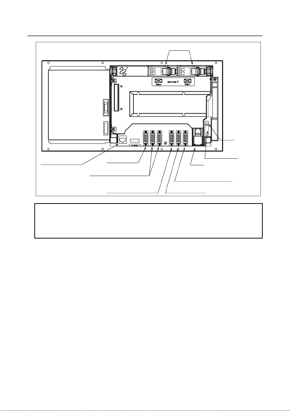
The configuration and component names of control units are shown in the figures given below. This
manual explains how to attach the connectors shown in these figures to devices. The numbers in
parentheses () in the figures are keyed to the item numbers of the descriptions in this manual. The
numbers in brackets [] in the figures are connector numbers.
1.1.1 Configurations of Control Units
Control units (A circle indicates that the corresponding unit is available.)
Display unit Touch panel MDI
(Horizontal)
LCD-mounted type
(Vertical)
(Horizontal)
LCD-mounted type
(Vertical)
Stand-alone type
(Vertical / Horizontal)
8.4-inch
color LCD
10.4-inch
color LCD
Absent
Present
Absent
Present
Expansion
slot
Absent 5+2 Available AvailableLCD-mounted type
2 5+2 Available N/A
Absent 5+2 Available Available
2 5+2 Available N/A
Absent 5+2 Available AvailableLCD-mounted type
2 5+2 Available N/A
Absent 5+2 Available Available
2 5+2 Available N/A
Absent 10+2 Available N/A
2 10+2 Available N/A
Absent Absent Available N/A
2 Absent Available N/A
Soft key
For the 8.4-inch color LCD, the touch panel is attached to only lathe system CNCs.
0i 0i Mate
- 1 -
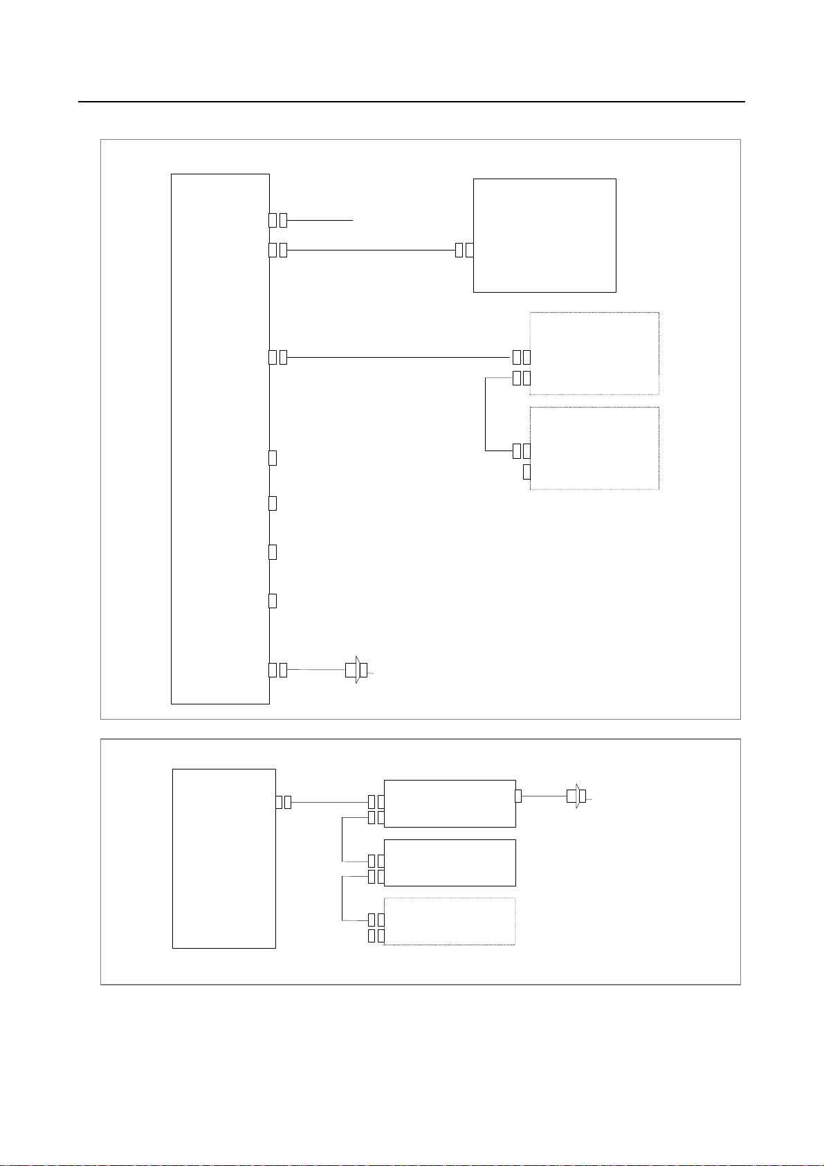
Page 20
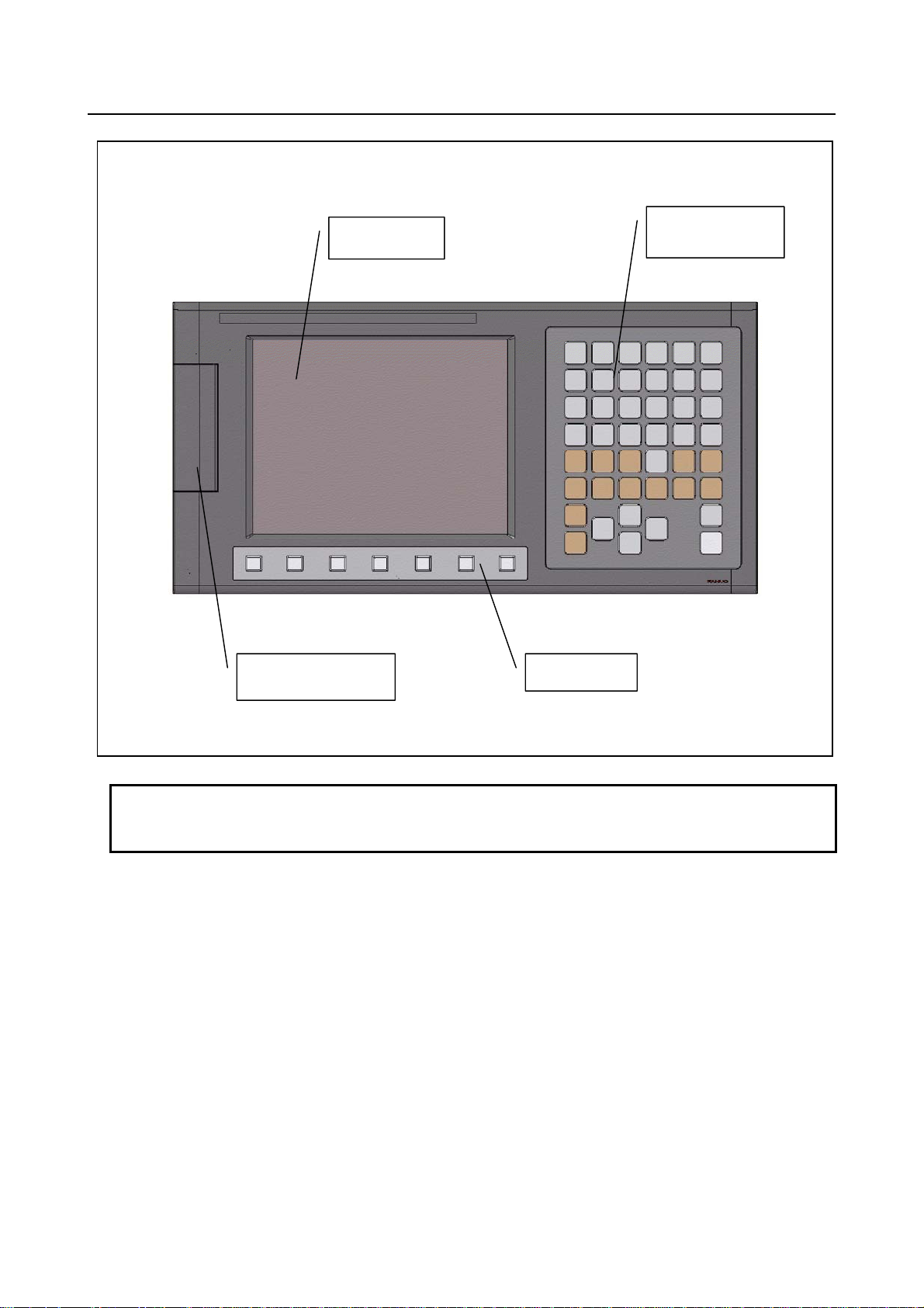
1.CONFIGURATION B-64303EN/03
terface
Control unit
LCD
MDI
(See Section 5.1)
Memory card
in
Soft key
NOTE
This figure is a front view of the 8.4-inch color LCD/MDI (horizontal) type control
unit.
- 2 -
Page 21
B-64303EN/03 1.CONFIGURATION
A
Control unit
Ethernet connector
[CD38A](See Section 5.4.)
Rear of unit
MDI connector
[JA2]
I/O device interface connector
[JD36A(left)/JD36A(right)]
nalog spindle connector or
high-speed skip conne c tor
[JA40] (See Section 5.3 or 6.2.)
Fan unit
Fuse
Power supply connector [CP1]
Battery
Serial spindle connector or position
coder connector
[JA41] (See Section 6.1 or 6.3.)
I/O-Link connector
[JD51A] (See Chapter 9.)
NOTE
This figure is a rear view of the control unit without option slots.
The numbers in parentheses () in the figures are keyed to the item numbers of
the descriptions in this manual. The numbers in brackets [] in the figures are
connector numbers.
- 3 -
Page 22
1.CONFIGURATION B-64303EN/03
(See Chapter 9.)
(See Chapter 9.)
(See Chapter 9.)
(See Chapter 9.)
(See Chapter 9.)
- 4 -
Page 23
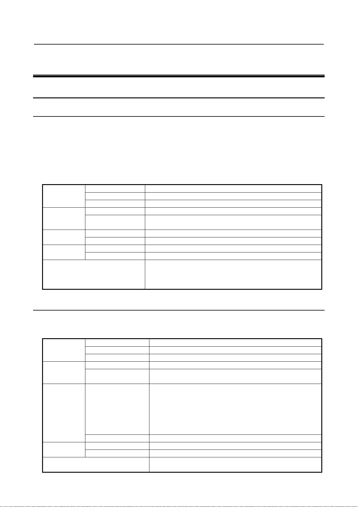
B-64303EN/03 1.CONFIGURATION
A
1.2 HARDWARE OVERVIEW
1.2.1 Control Unit Overview
Fast Ethernet board
Data s erver func tion
Ethernet communication function
• CPU fo r c ontrolling C NC
• Power supply
• Axis control
• Spindle in te r fa c e
• LCD/MDI inte rfa ce
• I/O Link
• PMC control fu n ction
• High-speed DI
• RS-232C
• Memo ry card interface
• Ethernet (
Main board
Series 0i only)
Basic system
Various types of network boards
Profibus master board
Profibus slave board
FL-net board
DeviceNet master board
DeviceNet slave board
The control unit of the Series 0i Mate has no optional slots, so no option board can be inserted.
unit with optional slots can have as many option boards as option slots.
The Fast Ethernet board can be inserted into only the slot on the LCD side.
Options
Unit without op tio nal slots
or
Unit having two optional slots
- 5 -
Page 24

2.TOTAL CONNECTION DIAGRAMS B-64303EN/03
p
A
A
r
A
2 TOTAL CONNECTION DIAGRAMS
LCD-mounted type control unit
Main board
LCD display unit
24V-IN(CP1)
(CA122)
MDI(JA2)
Soft key cable
MDI UNIT
CK1
24 VDC power supply
R232-1(JD36A)
R232-2(JD36B)
A-OUT&HDI(JA40)
I/O Link(JD51A)
SPDL(JA41)
FSSB(COP10A)
24VDC
24VDC
To 3rd spindle
To 2nd spindle
RS-232-C I/O device
{
nalog output for tool drives
High-peed skip input
Distributed I/O
board
CPD1
JD1B
JD1A
CPD1
JD1B
JD1A
COP10B
COP10A
RS-232-C I/O device
Touch panel
JA3
Distributed
I/O board,
I/O unit, etc.
C reacto
αi PS
i
SP
α
i
SV
α
Manual pulse generator
Operator's
anel
Power
magnetics
cabinet
Circuit breaker
200VAC
MCC
Position coder
Serial spindle motor
200VAC
Circuit breaker
Servo motor
COP10B
COP10A
COP10B
COP10A
COP10B
COP10A
(In this figure, a 1-axis amplifier is used.)
Separate detector interface unit 1
24VDC
ETHERNET(CD38A)
CP11A
COP10B
COP10A
CNF1
Separate detector interface unit 2
CP11A
Ethernet
α
αi SV
α
JF101
JF102
JF103
JF104
JA4A
JF101
JF102
JF103
JF104
i
SV
i
SV
Linear scale, axis 1
Linear scale, axis 2
Linear scale, axis 3
Linear scale, axis 4
bsolute scale battery
(Required only when an absolute scale is used)
Linear scale, axis 1
Linear scale, axis 2
Linear scale, axis 3
Linear scale, axis 4
Servo motor
Servo motor
Servo motor
- 6 -
Page 25
B-64303EN/03 2.TOTAL CONNECTION DIAGRAMS
A
A
A
A
When optional functions are provided
Fast Ethernet board
Optional slot
Memory card
ETHERNET(CD38R)
PROFIBUS-DP
master board
PROFI(CN1)
PROFIBUS-DP
slave board
PROFI(CN2)
DeviceNet
master board
DVNET(TBL)
DeviceNet
slave board
Prepare the memory card recommended by FANUC.
Ethernet
nother NC or Profibus device
nother NC or Profibus device
nother NC or Profibus device
DVNET(TBL)
FL-net board
FLNET(CD38N)
nother NC or Profibus device
FL-net device
- 7 -
Page 26
2.TOTAL CONNECTION DIAGRAMS B-64303EN/03
Example of I/O Link connection
Series 0
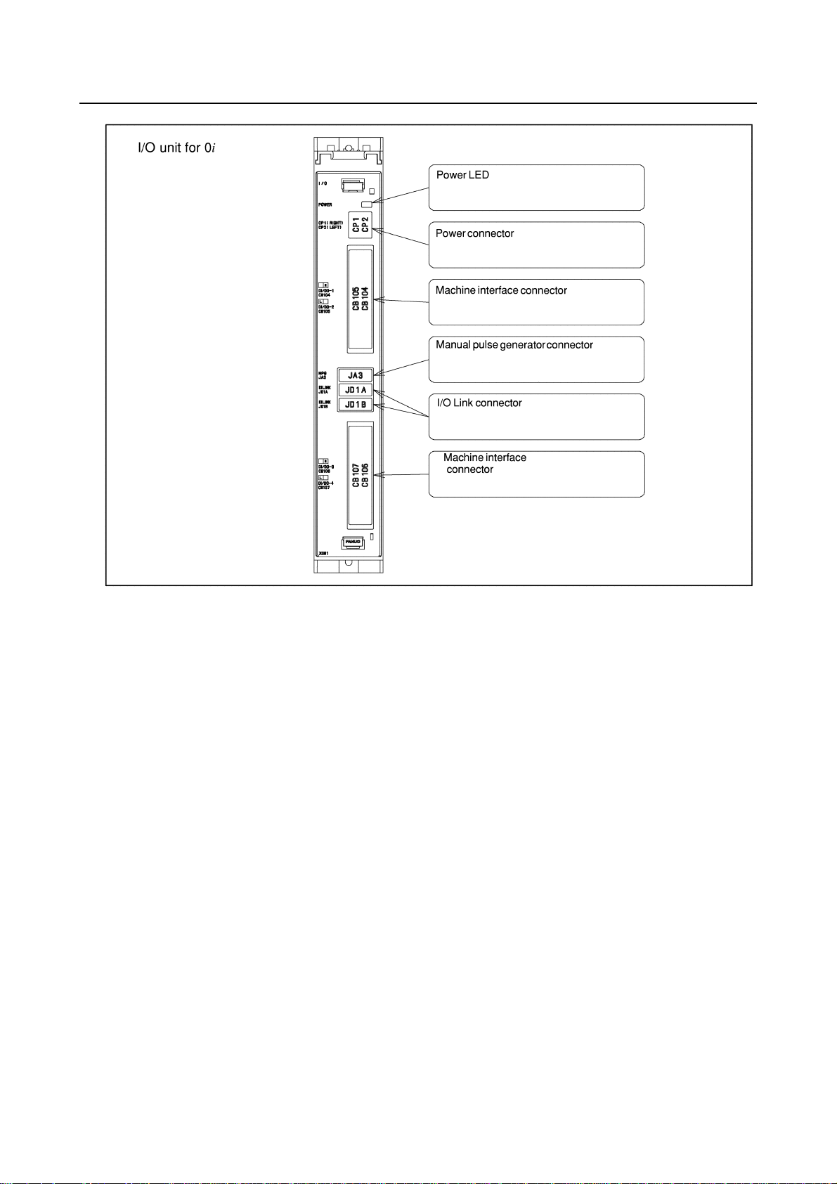
i
I/O Unit for 0i
(CP1)
I/O Link (JD1B)
I/O Link (JD1A)
DI : 96 points
DO : 64 points
DI/DO-1
(CB104)
DI/DO-2
(CB105)
DI/DO-3
(CB106)
DI/DO-4
(CB107)
Series 0i
Main board
24VDC
JD51A
I/O for operator’s
I/O Link
panel
JD1B
JD1A
I/O Link βi
servo amplifier
JD1B
JD1A
The order in which slave devic es are
connected via I/O Link can be
determined freely.
MPG(JA3)
Manual pulse generator (up to three units)
Series 0i Mate
Series 0i Mate
Main board
I/O Link (JD51A)
I/O Link
I/O for operator’s panel(with MPG)
JD1B
JD1A
I/O for operator’s panel
JD1B
JD1A
I/O Link βi servo
amplifier
The order in which slave de vices are connected via
I/O Link can be determined free ly.
JA3
(without MPG)
Manual pulse generator
(up to three units)
(For the 0i Mate, the numbe r of co nn ec table
amplifiers depends on the model.)
- 8 -
Page 27
B-64303EN/03 3.INSTALLATION
3 INSTALLATION
3.1 ENVIRONMENTAL REQUIREMENTS
3.1.1 Environmental Conditions External to Cabinets
The peripheral units and the control unit have been designed on the assumption that they are housed in
closed cabinets. In this manual "cabinet" refers to the following:
• Cabinet manufactured by the machine tool builder for housing the control unit or peripheral units;
• Operation pendant, manufactured by the machine tool builder, for housing the LCD/MDI unit or
operator's panel.
• Equivalent to the above.
The environmental conditions when installing these cabinets shall conform to the following table.
Ambient
temperature of
cabinets
Humidity
Vibration
sea level
Environment
Operating 0°C to 45°C
Storage, Transport −20°C to 60°C
Temperature change 0.3°C/minute or less
Normal 75%RH or less, no condensation
Short period
(less than 1 month)
Operating 0.5G or less
Non-operating 1.0G or less
Operating Up to 1000 m (Note) Meters above
Non-operating Up to 12000 m
Normal machine factory environment (These conditions need to be
reviewed separately when the cabinets are installed in an environment
where the concentrations of dust, coolant, organic solvent, and
corrosive gases are relatively high.)
95%RH or less, no condensation
3.1.2 Environmental Conditions of the Control Unit
The environmental conditions for installing the control unit in the cabinets are shown in the following
table. Section 3.3 describes the installation and design conditions of a cabinet satisfying these
conditions.
Ambient
temperature
Humidity
Vibration
sea level
Environment
Operating 0°C to 58°C
Storage, Transport −20°C to 60°C
Temperature change 0.3°C/minute or less
Normal 75%RH or less, no condensation
Short period
(less than 1 month)
A FANUC evaluation test is performed under the following conditions.
10 to 58Hz: 0.075 mm (amplitude)
Operating
Non-operating 1.0G or less
Operating Up to 1000 m (Note) Meters above
Non-operating Up to 12000 m
58 to 500Hz: 1 G
Vibration directions: X, Y, and Z directions
Scanning frequency: 10 cycles
IEC68-2-6 compliant
Prevent coolant, lubricant, and chippings from being applied directly
to on the control unit. Make sure that corrosive gas is not present.
- 9 -
95%RH or less, no condensation
0.5G or less
Page 28
3.INSTALLATION B-64303EN/03
Normal machine factory environment (take protective measures when
Atmosphere outside the cabinet
the control unit is used in an environment where the concentration of
dust, coolant, organic solvent, corrosive gas is relatively high.)
NOTE
1 If the CNC is installed 1000 m or higher above sea level, the allowable upper
ambient temperature of the CNC in the cabinet is changed as follows.
Assume that the allowable upper ambient temperature of the CNC in the cabinet
installed 1000 m or higher above sea level decreases by 1.0°C for every 100 m
rise in altitude.
Example)
The upper allowable ambient temperature of the CNC in the cabinet installed
1750 m above sea level is:
58°C-(1750-1000)/100×1.0°C=50.5°C
Therefore, the allowable ambient temperature range is from 0°C to 50.5°C.
2 When using a unit for which the installation conditions are specified separately,
the conditions also need to be met.
3.2 POWER SUPPLY CAPACITY
3.2.1 Power Supply Capacities of CNC-related Units
The following CNC-related units require an input power supply that satisfies the indicated current
capacities with a power supply voltage of 24 VDC ±10%. Here, note that momentary voltage changes
and ripples are also within ±10% of the power supply voltage.
Table 3.2.1 (a) Power supply capacity
Unit Power supply capacity Remarks
With no-optional slot
With two optional slots
Optional board
Fast Ethernet board
Profibus master board
Profibus slave board
FL-net board
DeviceNet master board
DeviceNet slave board
NOTE
1 The liquid-crystal display and MDI unit are included. Optional boards are not
included.
2 When connecting an RS-232-C unit (powered by the NC) to the RS-232-C port,
add the current capacity of the unit. Up to 1 A can be supplied from the two
channels of the port.
3 Use memory cards that consume no more than 2 W.
4 For other peripheral units (such as I/O units), see Table 3.2.1 (b) and also refer
to the relevant manuals.
5 When you select the input DC power supply for the CNC control section,
consider the restrictions other than the power supply capacity. Be sure to see
also Subsection 4.2.2.
1.5A
1.7A
0.2A
0.2A
0.1A
0.2A
0.1A
0.1A
Note 1) Control unit
Note 1)
- 10 -
Page 29
B-64303EN/03 3.INSTALLATION
Table 3.2.1 (b) Power supply rating (peripheral units)
Unit Power supply capacity Remarks
MDI unit 0A
Standard machine operator’s panel 0.4A
Operator's panel I/O module 0.3A+7.3mA×DI
Connector panel I/O module (basic) 0.2A+7.3mA×DI
Connector panel I/O module (additional) 0.1A+7.3mA×DI
I/O unit for 0i
Separate detector interface unit 0.9A Basic 4-axis unit only
Separate detector interface unit 1.5A Basic 4 axes + additional 4 axes
0.3A+7.3mA×DI
NOTE
The power supply capacity for DO is not assumed for I/O units.
3.3 DESIGN AND INSTALLATION CONDITIONS OF THE
MACHINE TOOL MAGNETIC CABINET
When a cabinet is designed, it must satisfy the environmental conditions described in Section 3.1. In
addition, the magnetic interference on the screen, noise resistance, and maintenance requirements must be
considered. The cabinet design must meet the following conditions :
(1) The cabinet must be fully closed.
The cabinet must be designed to prevent the entry of airborne dust, coolant, and organic solvent.
(2) The cabinet must be designed so that the permissible temperature of each unit is not exceeded. For
actual heat design, see Section 3.4.
(3) A closed cabinet must be equipped with a fan to circulate the air within. (This is not necessary for
a unit with fan.)
The fan must be adjusted so that the air moves at 0.5 m/sec along the surface of each installed unit.
CAUTION
If the air blows directly from the fan to the unit, dust easily adheres to the unit.
This may cause the unit to fail. (This is not necessary for a unit with fan.)
(4) For the air to move easily, a clearance of 100 mm is required between each unit and the wall of the
cabinet.
(5) Packing materials must be used for the cable port and the door in order to seal the cabinet.
(6) The display unit must not be installed in such a place that coolant would directly fall onto the unit.
The control unit has a dust-proof front panel, but the unit should not be placed in a location where
coolant would directly fall onto it.
(7) Noise must be minimized.
As the machine and the CNC unit are reduced in size, the parts that generate noise may be placed
near noise-sensitive parts in the magnetics cabinet.
The CNC unit is built to protect it from external noise. Cabinet design to minimize noise
generation and to prevent it from being transmitted to the CNC unit is necessary. See section 3.5
for details of noise elimination/management.
(8) When placing units in the cabinet, also consider ease of maintenance.
The units should be placed so that they can be checked and replaced easily when maintenance is
performed.
(9) The installation conditions of the I/O unit and connector panel I/O module must be satisfied.
To obtain good ventilation in the module, the I/O unit and connector panel I/O module must be
installed in the direction shown in the following figure. Clearances of 100 mm or more both above
and below the I/O unit are required for wiring and ventilation.
- 11 -
Page 30
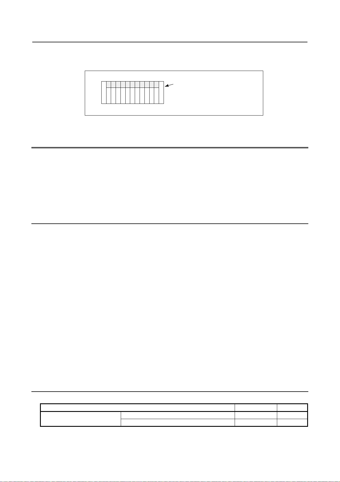
3.INSTALLATION B-64303EN/03
Equipment radiating too much heat must not be put below the I/O unit and connector panel I/O
module.
Top
Connector panel I/O module or
I/O base unit
(No screws or protrusions shall extend
from the bottom of this unit.)
Bottom
3.4 THERMAL DESIGN OF THE MACHINE TOOL MAGNETIC
CABINET
The internal air temperature of the cabinet increases when the units and parts installed in the cabinet
generate heat. Since the generated heat is radiated from the surface of the cabinet, the temperature of the
air in the cabinet and the outside air balance at certain heat levels. If the amount of heat generated is
constant, the larger the surface area of the cabinet, the less the internal temperature rises. The thermal
design of the cabinet refers to calculating the heat generated in the cabinet, evaluating the surface area of
the cabinet, and enlarging that surface area by installing heat exchangers in the cabinet, if necessary.
Such a design method is described in the following subsections.
3.4.1 Temperature Rise within the Machine Tool Magnetic Cabinet
The cooling capacity of a cabinet made of sheet metal is generally 6 W/°C per 1m2 surface area, that is,
when the 6W heat source is contained in a cabinet having a surface area of 1 m
in the cabinet rises by 1°C. In this case the surface area of the cabinet refers to the area useful in
cooling , that is, the area obtained by subtracting the area of the cabinet touching the floor from the total
surface area of the cabinet. There are two preconditions : The air in the cabinet must be circuited by the
fun, and the temperature of the air in the cabinet must be almost constant.
In the case of the operator's panel cabinet for example, to limit the temperature within the operator's panel
cabinet to 58°C or less when the ambient temperature is 45°C, satisfy the following expression.
Internal heat loss P [W] ≤
2
6[W/m
⋅°C] × surface area S[m2] × 13[°C] of rise in temperature
(A cooling capacity of 6 W/°C assumes the cabinet is so large that agitation with the fan motor does not
make the temperature distribution uniform. For a small cabinet like the operator's panel, a cooling
capacity of 8 W/°C, indicated in Subsection 3.4.4, may be used.)
For example, a cabinet having a surface area of 4m
2
has a cooling capacity of 24W/°C. To limit the
internal temperature increase to 13°C under these conditions, the internal heat must not exceed 312W.
If the actual internal heat is 360W, however, the temperature in the cabinet rises by 15°C or more.
When this happens, the cooling capacity of the cabinet must be improved using the heat exchanger.
In the case of the power magnetics cabinet for housing cabinet the I/O unit for 0i, limit the internal
temperature increase to 10°C or less, not 13°C or less.
2
, the temperature of the air
3.4.2 Heat Output of Each Unit
Table 3.4.2 (a) Heat output
Unit Heat output Remarks
With no-optional slot
With two optional slots
- 12 -
33W
37W
Note 1) Control unit
Note 1)
Page 31

B-64303EN/03 3.INSTALLATION
Unit Heat output Remarks
Optional board
Fast Ethernet board
Profibus master board
Profibus slave board
FL-net board
DeviceNet master board
DeviceNet slave board
6W
5W
2W
5W
3W
3.5W
Note 2)
NOTE
1 The liquid-crystal display and MDI unit are included. Optional boards are not
included.
2 When installing the CF card on the Fast Ethernet board, add 0.3 W for the Fast
Ethernet board to the heat output. (The heat output of the CF card may be
changed if its specification is changed.)
Table 3.4.2 (b) Heat output
Unit Heat output Remarks
MDI unit 0W
Standard machine operator’s panel 15W Note 1)
Operator's panel I/O module 12W Note 1)
Connector panel I/O module (basic) 8W Note 1)
Connector panel I/O module (additional) 5W Note 1)
I/O unit for 0i
Separate detector interface unit 9W Basic 4-axis unit only
Separate detector interface unit 14W Basic 4 axes + additional 4 axes
16W Note 1)
Note 2)
Note 2)
NOTE
1 The indicated values are when 50% of the module input signals are ON.
2 Heat output generated within the separate detector is not included.
3.4.3 Thermal Design of Operator's Panel
With a small cabinet like the operator's panel, the heat dissipating capacity of the cabinet is as shown
below, assuming that there is sufficient mixing of the air inside the cabinet.
Coated metal surfaces: 8 W/m
Plastic surfaces: 3.7 W/m
An example of the thermal design for the cabinet shown in Fig. 3.4.3 is shown below.
2
°C
2
°C
- 13 -
Page 32

3.INSTALLATION B-64303EN/03
Fig. 3.4.3
Assume the following.
Thermal exchange rates
2
Coated metal surfaces : 8 W/m
Plastic surfaces : 3.7 W/m
⋅°C
2
⋅°C
Allowable temperature rise : 13°C higher than the exterior temperature
Also, assume the following.
Dimensions of pendant type cabinet shown in Fig. 3.4.3 : 560(W) × 470(H) × 150(D) mm
Surface area of metallic sections : 0.5722 m
Surface area of plastic sections : 0.2632 m
2
2
In this case, the allowable total heat dissipation for the cabinet is:
8 × 0.5722 × 13 + 3.7 × 0.2632 × 13 = 72 W.
In consequence, it can be concluded that the units shown in Table 3.4.3 on the next page can be installed
in this cabinet.
Table 3.4.3
Control unit (Optional two-slots) 37W
Optional board (Fast data server board) 3W
Optional board (Profibus master board) 5W
Standard machine operator's panel 15W
120-mm square fan motor for air mixing 8W
Total heat dissipation of the above 68W
NOTE
The 15 W quoted for the standard machine operator's panel represents an
example heat output value when half of all the input signals are turned on. This
value varies, depending on the mechanical configuration.
- 14 -
Page 33

B-64303EN/03 3.INSTALLATION
3.5 COUNTERMEASURES AGAINST NOISE
The CNC has been steadily reduced in size using surface-mount and custom LSI technologies for
electronic components. The CNC also is designed to be protected from external noise. However, it is
difficult to measure the level and frequency of noise quantitatively, and noise has many uncertain factors.
It is important to prevent both noise from being generated and generated noise from being introduced into
the CNC. This precaution improves the stability of the CNC machine tool system.
The CNC component units are often installed close to the parts generating noise in the power magnetics
cabinet. Possible noise sources into the CNC are capacitive coupling, electromagnetic induction, and
ground loops.
When designing the power magnetics cabinet, guard against noise in the machine as described in the
following section.
3.5.1 Grounding
Grounding the power magnetics cabinet and devices is very important to prevent an electric shock and
suppress a noise influence. The following describes the grounding methods for suppressing the noise
influence.
3.5.1.1 About grounding types
The CNC system uses the following three types of grounding:
(1) Signal grounding
This type of grounding is used to supply a reference potential (0 V) for the electrical signal system.
(2) Frame grounding
This type of grounding is used for safety reasons as well as to suppress external and internal noise.
For example, grounding is provided for the device frames, panels, and shielding on the interface
cables connecting the devices.
(3) System grounding (PE)
This type of grounding is used to connect frame grounds, which are provided for the individual
devices or between the units, to the ground as a system at a single point.
3.5.1.2 Grounding methods
Typically, noise that becomes a problem is high–frequency noise. To suppress high–frequency noise, it is
important that the devices are grounded at low impedance(NOTE).
The grounding schemes for this purpose are described below.
(1) Multipoint grounding scheme
In this grounding scheme, when grounded at sufficiently low impedance, the cabinet metal plates are
used as ground plates, to which grounding is provided in the vicinity of each device.
This scheme has a great effect of suppressing high–frequency noise because it enables grounding to
the low–impedance metal plates of the cabinet in the shortest distance. However, the noise
suppression effect depends on the cabinet structure because the cabinet metal plates are used as
ground plates.
See Subsection 3.5.1.4 for the cabinet. Fig. 3.5.1.2 (a) is a schematic wiring diagram.
When the multipoint grounding scheme is adopted, the units can be grounded at low impedance, and
ground wires can be shortened, so that wiring may be simplified.
- 15 -
Page 34

3.INSTALLATION B-64303EN/03
(2) Single–point grounding scheme
In this grounding scheme, grounding separation is achieved between the signal system and power
system, and grounding is provided at a single point to suppress the noise influence of the power
system on the signal system.
This scheme tends to need longer connection wires for grounding the devices. To produce a
sufficient effect of suppressing high–frequency noise, it is therefore necessary to use larger–diameter
wires or use two or more wires for each connection. Fig. 3.5.1.2 (b) is a schematic wiring diagram.
NOTE
Impedance includes a resistance component that converts electric current to
heat as well as a component called “reactance”, and indicates a characteristic of
resistance to the flow of alternating current at a certain frequency.
- 16 -
Page 35

B-64303EN/03 3.INSTALLATION
α
α
α
A
p
p
SV
i
anel
CNC
erator’s
O
Ground bar for shield
clamp
Pendant box
(Lowe-impedance metal plates)
Connection at
low impedance
Signal
line
line
Power
Machine side
Frame grounding
System grounding (PE)
Separate the signal line
and power line when
routing them.
JF*
SP
i
PS
i
CX1
Cabinet
(Lowe-impedance metal plates)
device.
in the vicinity of a
Provide grounding
Fig. 3.5.1.2 (a) Schematic diagram for multipoint grounding scheme
supply
24V power
AC input
- 17 -
System ground (PE)
surface of a ground wire.
Note) Do not apply a coating to the connection
Page 36

3.INSTALLATION B-64303EN/03
A
Operator
s panel
α
α
α
Pendant box
SV
i
Machine side
’
CNC
Signal system ground bar
line
Signal
Ground bar for shield clamp
line
Power
Frame grounding
System grounding (PE)
Separate the signal line and
power line when routing them.
JF*
SP
i
ground bar
PS
i
Cabinet
CX1
chieve grounding
separation between
the signal system
and power system.
Fig. 3.5.1.2 (b) Schematic diagram for single–point grounding scheme
Power system
24V power
Signal system ground bar
supply
AC input
System grounding (PE)
- 18 -
Page 37

B-64303EN/03 3.INSTALLATION
3.5.1.3 Cable clamp and shield processing
Signal lines basically require shield clamps. The influence of external noise can be suppressed by
properly providing the signal lines with the shield clamps.
Partially peel the sheath off a cable and expose the shield, and press the exposed portion against the
ground bar with the clamp. Care should be taken so that the ground bar and shield have a surface contact
in a larger area. (See the figure below.)
When the multipoint grounding scheme is used, care should be taken so that the ground bar for the shield
clamp and cabinet are connected at low impedance by, for example, preventing the cabinet side contact
surface from being coated.
Ground plate
Cable
Metal fittings fo r
clamp
40 to 80
Fig. 3.5.1.3 (a) Cable clamp (1)
NOTE
Select a cable with a proper length.
If the cable is too long, the noise immunity may be reduced or noise may be
caused on other cables. In addition, when the excess length is coiled, the
inductance is increased and a high voltage is induced during turning on or off of
signals. This may cause a malfunction due to a failure or noise.
- 19 -
Page 38

3.INSTALLATION B-64303EN/03
Control unit
Metal fittings for
clamp
Shield cover
Fig. 3.5.1.3 (b) Cable clamp (2)
Machine side
installation board
Ground plate
NOTE
Bundle the cables connected to a CNC or amplifier near each unit and shield
them.
Prepare ground plate like the following figure.
Ground terminal
(grounded)
Hole for securing
metal fitting clamp
Mount screw hole
Fig. 3.5.1.3 (c) Ground plate
For the ground plate, use a metal plate of 2 mm or thicker, which surface is plated with nickel.
- 20 -
Page 39

B-64303EN/03 3.INSTALLATION
8
12
20
Fig. 3.5.1.3 (d) Ground plate holes
(Reference) Outer drawings of metal fittings for clamp.
Max. 55
Ground plate
28
6
17
Fig. 3.5.1.3 (e) Outer drawings of metal fittings for clamp
Ordering specification for metal fittings for clamp
A02B-0124-K001 (8 pieces)
3.5.1.4 Cabinet
A cabinet is an important element in improving noise immunity and suppressing radiated noise. One of
the causes of problems related to noise immunity and radiated noise is faulty electrical continuity between
the metal plates that make up the cabinet. Typically, noise that becomes a problem is high–frequency
noise, against which measures must be taken in the cabinet design.
(1) Basic cabinet structure
A cabinet should basically be made of metal.
To improve noise immunity, there must be low–impedance electrical continuity between the metal
plates that make up the cabinet, which are the side plates, top plate, and bottom plate, and a
welding–type cabinet structure is recommended.
- 21 -
Page 40

3.INSTALLATION B-64303EN/03
As for a cabinet welding method, bead welding is more suitable than spot welding for providing
low–impedance electrical continuity between the metal plates.
For an assembly–type cabinet structure, provide electrical continuity by bringing the metal plates
into direct contact with each other, without applying a coating to their joint surface areas.
In a structure that has the metal plates connected only with wires because of structural constraints,
low–impedance connections are more difficult to make than in a structure in which welding is made
or the metal plates are brought into direct contact with each other. It is necessary to maintain
sufficient levels of items such as the cross–sectional area of a wire to use, continuity of connections,
and contact areas.
Bead welding
Bring the metal plates into direct contact with each
other, without applying a coating to their joint areas.
NOTE
For improved noise immunity, how to provide low-impedance electrical continuity
in the cabinet is described here. To construct a protective circuit, a protective
grounding connection must be made between the metal plates by using electric
wires with a cross-sectional area appropriate for the AC input power capacity of
the unit mounted on each metal plate.
(2) Mounting units on the cabinet
The shortest possible lengths of unit ground wires should be used to make connections. A ground
wire with a small conductor diameter causes impedance to high-frequency noise to become
particularly higher, leading to an insufficient grounding effect. For the location of the ground
terminal of each unit, refer to the manual relevant to the unit. The following shows the
recommended method by which the metal plate with the unit mounted is installed on the cabinet.
Care should be taken so that the cabinet and metal plate are connected to each other on their broad
areas with no coating. It is not recommended that electrical continuity be provided only by screws,
because impedance to high frequency cannot be sufficiently low.
- 22 -
Page 41

B-64303EN/03 3.INSTALLATION
<Good example>
Metal
plate
Unit
Cabinet
Shortest connection
with thick ground wire
<Bad example>
Continuity only by
screw in a coated area
Continuity on areas with
no coating
Cabinet
Metal
plate
Unit
Thin ground wire,
long ground wire
3.5.2 Connecting the Ground Terminal of the Control Unit
Connecting the 0 V output in the CNC to a protective circuit (ground)
The IEC 204-1 and JIS B 6015 standards specify the following:
- Protection against malfunctions due to ground faults
“To make the control circuit prevent malfunctions of a machine tool due to a ground fault and not to
prevent the machine tool from stopping, either of the ground and electronic circuits shall be connected to
a protective circuit.”
Note that for each FANUC CNC, the 0V output in the CNC is connected to a protective circuit (ground).
- 23 -
Page 42

3.INSTALLATION B-64303EN/03
A
Machine
24 VDC power
supply
Relay
Output
signal
Power
magnetics
cabinet
NC ground terminal
This bold line indicates grounding for the control unit described in the connection manual.
s shown in this figure, by just connecting the ground terminal of the control unit to the machine ground,
the 0 V output of the relay circuit in the power magnetics cabinet is connected to the ground (protective
circuit).
Machine protective circuit (ground) network
Connection to the ground in the user factory
- 24 -
Page 43

B-64303EN/03 3.INSTALLATION
For the 8.4" LCD/MDI (horizontal) type
Unit back face
M4 screw
For the 8.4" LCD/MDI (vertical) type
Grounding cable
Unit back face
M4 screw
For the 10.4" LCD type
Unit back face
M4 stud
Connect the 0V line in the control unit to the ground plate of the cabinet via the protective ground
terminal (shown in the above figure).
For the locations of the ground terminals of the other units, see the external dimensions of each unit in the
appendix.
- 25 -
Page 44

3.INSTALLATION B-64303EN/03
3.5.3 Separating Signal Lines
The cables used for the CNC machine tool are classified as listed in the following table.
Process the cables in each group as described in the action column.
Group Signal line Action
A
B
C
NOTE
1 Binding the cables in one group separately from another means that the groups
are placed 10 cm or more apart from one another.
2 Covering a group with an electromagnetic shield means that shielding is
provided between groups with grounded steel plates.
3 The shield is not required when the cable between the CNC and MDI is no more
than 30 cm in length.
Primary AC power line
Secondary AC power line
AC/DC power lines (containing the power lines for
the servo and spindle motors)
AC/DC solenoid
AC/DC relay
DC solenoid (24 VDC)
DC relay (24 VDC)
DI/DO cable between the I/O unit and power
magnetics cabinet
DI/DO cable between the I/O unit and machine
24 VDC input power cables connected to the
control unit and its peripherals
Cable between the CNC and I/O unit
Cable for position and velocity feedback
Cable between the CNC and spindle amplifier
Cable for the position coder
Cable for the manual pulse generator
Cable between the CNC and the MDI (Note 3)
RS–232C and RS–422 interface cable
Cable for the battery
Other cables for which shield processing is
specified
Bind the cables in group A separately (Note 1)
from groups B and C, or cover group A with an
electromagnetic shield (Note 2).
See Subsection 3.5.4 and connect spark killers
or diodes with the solenoid and relay.
Connect diodes with the DC solenoid and relay.
Bind the cables in group B separately from
group A, or cover group B with an
electromagnetic shield.
Separate group B as far from group C as
possible.
It is desirable to perform shield processing.
Bind the cables in group C separately from
group A, or cover group C with an
electromagnetic shield.
Separate group C as far from group B as
possible.
Be sure to perform shield processing as
described in Subsection 3.5.5.
- 26 -
Page 45

B-64303EN/03 3.INSTALLATION
3.5.4 Noise Suppressor
The AC/DC solenoid, AC/DC relay, and other devices are used in the power magnetics cabinet.
A high pulse voltage is caused by coil inductance when these devices are turned on or off.
This pulse voltage is induced through a cable or any other component, causing the electronic circuits to be
disturbed.
Take the following measures against the pulse voltage:
1) See Subsection 3.5.3 for groups A and B, and use spark killers for AC circuits or diodes for DC
circuits.
2) See “Notes on selecting the spark killer” below for information about selection of spark killers or
diodes.
Notes on selecting the spark killer
• Use a CR–type spark killer. (Use it for AC circuits.)
(A varistor is useful in clamping the peak pulse voltage, but cannot suppress the sudden rise of the
pulse voltage. FANUC therefore recommends the use of a CR–type spark killer.)
• The reference CR values of the spark killer shall conform to the following based on the current ((I
(A)) and DC resistance of the coil in the stationary state:
1) Resistance (R) : Equivalent of the DC resistance of the coil
22
II
~
2) Capacitance (C) :
10
I :Current of the coil in the stationary state [A]
(μF)
20
- 27 -
Page 46

3.INSTALLATION B-64303EN/03
A
Equivalent circuit of the spark killer
C relay
Spark killer
Mount the noise eliminator near a motor or a relay coil.
RC
Spark killer
Motor
NOTE
Use a CR-type noise eliminator. Varistor-type noise eliminators clamp the peak
pulse voltage but cannot suppress a sharp rising edge.
Diode (used for direct-current circuits)
Diode
DC relay
Use a diode which can withstand a voltage up
to two times the applied voltage and a current
up to two times the applied current.
3.5.5 Measures Against Surges due to Lightning
To protect equipment from surge voltages caused by lightning, install a lightning surge protector between
lines and between a line and ground. For how to install protectors, see Appendix A "FITTING A
LIGHTNING SURGE PROTECTION DEVICE" in FANUC SERVO AMPLIFIER αi series
DESCRIPTIONS (B-65282EN).
Lightning surge protector specifications
Ordering number Specification Remarks
For line-to-line installation:
A06B-6077-K142
A06B-6077-K143
A06B-6077-K144
RAV-781BYZ-2
For line-to-ground installation:
RAV-781BXZ-4
For line-to-line installation:
RAV-152BYZ-2A
For line-to-ground installation:
RAV-801BXZ-4
Integration type for line-to-line
installation/line-to-ground installation:
RCM-601BUZ-4
* The line-to-line or line-to-ground installation type (A06B-6077-K144) and the integration type
(A06B-6077-K142) are equivalent in performance and specifications.
Manufactured by Okaya Electric Industries Co., Ltd.
For 200VAC line
TÜV approved products
Manufactured by Okaya Electric Industries Co., Ltd.
For 400VAC line
TÜV approved products
Manufactured by Okaya Electric Industries Co., Ltd.
For 200VAC line
TÜV approved products
- 28 -
Page 47

B-64303EN/03 3.INSTALLATION
t
3.6 CONTROL UNIT
3.6.1 Installation of the Control Unit
The control unit has a built–in fan motor.
Air enters the control unit through the bottom and is drawn through the fan motor which is located on the
top of the control unit.
Space (A), shown in Fig. 3.6.1, must be provided to ensure unrestricted air flow. Also, space (B) should
be provided whenever possible. When space (B) cannot be provided, ensure that nothing is placed in the
immediate vicinity which could obstruct the air flow.
For a horizontal uni
For a vertical unit
Fig. 3.6.1
Unit : mm
- 29 -
Page 48

3.INSTALLATION B-64303EN/03
Installing the I/O unit for 0i
Fig. 3.6.2
3.7 SEVERE DUST/LIQUID PROTECTION OF CABINETS AND
PENDANT BOXES
Since a cabinet or pendant box, which is designed by the machine tool builder, for housing display units
or operator's panels is likely to receive dust particles, chippings, or greasy fumes, so keep the following in
mind to keep them out.
1) The cabinet and pendant box must be of a hermetically sealed structure.
2) Apply packing to the panel mounting surface to which a display and operator's panel are to be
mounted.
Apply packing to the panel mounting surfaces of other units mounted on the same case for
dust/liquid protection.
3) Make sure that the door packing of the cabinet and pendant box is sealed firmly.
4) For a cabinet or pendant box with a rear cover, apply packing to the mounting surface.
5) Make sure that the cable entrance is sealed with packing, connectors for conduits, etc.
6) Make sure that all other openings are blocked, if any.
7) Make sure that the display and operator's panel do not receive cutting debris and coolant directly.
- 30 -
Page 49

B-64303EN/03 3.INSTALLATION
8) Since coolant accumulated on the top of a cabinet or pendant box may drip onto the panel surface of
a display unit of operator's panel, use a structure that prevents coolant from being accumulating on
the top or from being dripping onto the panel surface. For example, install a canopy over a display
unit or operator's panel.
9) The front surface of a display unit must be vertical. Otherwise, coolant is likely to accumulate in
the lower part of the display screen.
- 31 -
Page 50

4.POWER SUPPLY CONNECTION B-64303EN/03
4 POWER SUPPLY CONNECTION
4.1 GENERAL
This chapter explains the connection of power supply for control unit.
4.2 TURNING ON AND OFF THE POWER TO THE CONTROL
UNIT
4.2.1 Power Supply for the Control Unit
Supply power (24VDC) to the control unit from an external sources.
Provide an ON/OFF circuit for turning the AC power on and off outside the unit as shown in Fig. 4.2.1.
To minimize the effect of noise or voltage fluctuations to the CNC, it is recommended that a power to the
CNC be provided independently of the power sources to devices with large noise or load fluctuations.
Fig. 4.2.1
4.2.2 External 24 VDC Power Specification and Circuit
Configuration
Specifications of recommended external 24 VDC power supply (regulated power supply): (The power
supply must satisfy UL1950.)
Output voltage:
+24 V ±10% (21.6 V to 26.4 V)
(including ripple voltage and noise. See the figure below.)
Output current:
The continuous load current must be larger than the current consumption of the CNC.
(At the maximum temperature inside the power magnetics cabinet in which the power supply is
located)
- 32 -
Page 51

B-64303EN/03 4.POWER SUPPLY CONNECTION
Load fluctuations (including rush current):
The output voltage must not go out of the above range due to load fluctuations by external DO and
other factors.
Instantaneous input interruption retention time:
10 ms (for -100%), 20 ms (for -50%)
Fig 4.2.2 (a) Timing chart
- Notes to take when the vertical axis exists
When the vertical axis exists, select the DC power supply that has a long voltage hold time to decrease
the amount of vertical axis falling during power-off (including a power failure).
If the operating voltage drops to less than or equal to 21.6V, the CNC releases servo activation.
Therefore, when the hold time for 24 VDC during AC power-off is too short, servo activation is released
before the breaks are applied because some peripheral circuit detects power-off. This may increase the
amount of vertical axis falling.
Generally, a power supply with sufficient power capacity tends to increase the hold time during
power-off.
- Circuit configurations
The following circuit configurations are not recommended.
Forbidden
<1> Circuit examples that cannot retain the output voltage at an instantaneous interruption (the voltage
reduces to 21.6 V or below)
- 33 -
Page 52

4.POWER SUPPLY CONNECTION B-64303EN/03
A
A
A
A
Example 1
Rectifier
C input
Example 2
C input
circuit
Rectifier
circuit
CNC unit
CNC unit
NOTE
The rectifier circuit means a circuit using diodes for full-wave rectification.
<2> Circuit examples that exceed the output voltage specifications (21.6 V to 26.4 V) due to an abrupt
load change
Example 1
C input
Example 2
C input
Regulated
power supply
Regulated
power supply
CNC unit
Device with
remarkable load
fluctuations
CNC unit
Device with large
rush current
For a circuit configuration in <2>, connect another regulated power supply to be specifically used for the
device with remarkable load fluctuations so that the CNC and other units are not affected.
Avoid the use of a configuration in <2> if possible, even in an environment with small load fluctuations
or rush current. When two or more units are connected to the same power supply, the 24-VDC power
may not be turned on due to a failure in a unit other than the CNC. If this happens, it takes much time to
locate the failure because the CNC cannot start and no alarm indication is provided.
When the CNC and other units are connected to the same power supply because of limited space for the
power magnetics cabinet or for some other reason, careful consideration must be given to possible rush
currents and voltage fluctuations. In addition, to prevent power supply noise from entering the CNC, a
noise filter must be inserted before the power to the CNC. (Recommended noise filter: ZGB2203-01U
manufactured by TDK)
- 34 -
Page 53

B-64303EN/03 4.POWER SUPPLY CONNECTION
A
Recommended
The following circuit configuration is recommended.
The power to the CNC and other, FANUC Servo Unit β series with an I/O link (β amplifier with an I/O
link), and so on in the sample configuration below) is assumed to be turned on or off at the same time.
(The power to any unit is not assumed to be turned on during operation or before the power to the CNC is
turned on.
C input
On/off
circuit
Regulated
power
supply
Regulated
power
supply
Fig 4.2.2 (b)
CNC unit
I/O Unit-A
amplifier with
β
an I/O link
Device with large noise
or load fluctuations
For example, the following units require 24VDC power sources.
• Various I/O Link slave units
• β servo amplifier and βi servo amplifierβ
• Separate detector unit
Caution
Turning the power to units on simultaneously when turning the power to the CNC:
When the following power-on timing condition is satisfied, the power to units is assumed to be turned on
simultaneously when the power to the CNC is turned on.
Power to the CNC
Power to units
(including the Power
Mate)
On
Off
On
Off
t1
t2
t1:200ms Means that the power to units (including the Power Mate) is turned on within 200 ms before
the power to the CNC is turned on.
t2:-500ms Means that the power to units (including the Power Mate) is turned on within 500 ms after
the power to the CNC is turned on.
- 35 -
Page 54

4.POWER SUPPLY CONNECTION B-64303EN/03
Turning the power to units off simultaneously when turning the power to the CNC off:
This means that the power to units may be turned off within 500 ms before the power to the CNC control
unit is turned off. If the power to units is turned off earlier, alarm information is left in the NC.
Power to the CNC
On
Off
t1
t1:500ms Means that the power to units are turned off within 500 ms before the power to the CNC is
turned off.
The power to the CNC must not be turned on or off with the power to units on.
4.2.3 Power-on Sequence
Turn on the power to all the units at the same time, or in the following sequence:
1 Power to the overall machine (200 VAC)
2 Servo amplifier control power supply (200 VAC)
3 Power to the slave I/O units connected via the I/O link, the separate detector interface unit, and the stand-alone
type LCD unit (24 VDC), power to the CNC controller (24 VDC), power to the separate detector (scale)
“Turning on the power to all the units at the same time” means completing the power–on operations in 1
and 2 above within 500 ms of performing power–on in 3.
Do not remove the memory backup battery (3VDC) and the separate absolute pulse coder battery (6VDC)
regardless of whether the power of the CNC controller is on or off. If the batteries are removed when
the CNC controller is off, the parameters and programs saved in the CNC controller and the position data
in the pulse coder are lost.
For information on replacing the memory backup battery, see Subsection 4.4.1.
4.2.4 Power-off Sequence
Turn off the power to all the units at the same time, or in the following sequence:
1 Power to the slave I/O units connected via the I/O link, the separate detector interface unit, and the CNC
controller (24 VDC)
2 Servo amplifier control power supply (200 VAC), power to the separate detector (scale)
3 Power to the overall machine (200 VAC)
When turning off the power of the CNC controller, be sure to turn off the power of units such as the slave
I/O devices connected through I/O Link, β amplifier with I/O Link, Power Mate and separate detector
interface unit, control power supply of the servo amplifier, and separate detector (such as a scale).
“Turning off the power to all units at the same time” means completing the power–off operations in 2 and
3 above within 500 ms before the power–off operation described in 1 above. If the power to the units
indicated in 2 or 3 is turned off other than within 500 ms of the power in 1 being turned off, alarm
information is left in the NC.
When the power is turned off or when the power is momentarily disconnected, processing must be
performed from the machine as necessary, because motor control is disabled.
For example, when movement along a vertical axis is controlled, a brake should be applied to prevent
falling. Usually , the brake clamps the motor when the servo is not activated or when the motor is not
turning. The clamp is released only when the motor is turning.
- 36 -
Page 55

B-64303EN/03 4.POWER SUPPLY CONNECTION
A
When servo axis control is disabled by power-off or momentary power disconnection, the brake usually
clamps the servo motor. In this case, before the relay for clamping operates, the controlled axis may fall.
So, also consider whether the distance the axis is likely to fall will cause a problem.
When the power is turned off:
Be sure to apply a brake for clamping before turning off the power to CNC.
When the power fails:
If a power failure is detected, a brake must be applied immediately. Select the power supply with a
longer DC power retention time after AC power-off, because the servo is deactivated if the power to
CNC is turned off.
4.3 CABLE FOR POWER SUPPLY TO CONTROL UNIT
Supply the power to the control unit from an external 24 VDC power supply.
CNC control unit
CP1
1
+24V
2
0V
3
External power
24VDC stabilized
power
24VDC ±10%
Cable
CP1
MP Japan
1-178288-3 (housing)
1-175218-5 (Contact)
+24V (1)
0V (2)
Recommended cable : A02B-0124-K830(5m)
(Crimp terminal of size M3 is available on the external power side)
4.4 BATTERIES
In a system using this CNC, batteries are used as follows:
Use Component connected to battery
Memory backup in the CNC control unit CNC control unit
Preservation of the current position indicated by the
separate absolute pulse coder
Preservation of the current position indicated by the
absolute pulse coder built into the motor
Separate detector interface unit
Servo amplifier
External power
Select a source that
meets the external
power terminal.
4.4.1 Battery for Memory Backup in the CNC Control Unit (3 VDC)
Offset data, and system parameters are stored in SRAM in the control unit. The power to the SRAM is
backed up by a lithium battery mounted on the front panel of the control unit. The above data is not lost
even when the main battery goes dead. The backup battery is mounted on the control unit at shipping.
This battery can maintain the contents of memory for about a year.
When the voltage of the battery becomes low, alarm message "BAT" blinks on the display and the battery
alarm signal is output to the PMC. When this alarm is displayed, replace the battery as soon as possible.
In general, the battery can be replaced within two or three weeks, however, this depends on the system
configuration.
- 37 -
Page 56

4.POWER SUPPLY CONNECTION B-64303EN/03
If the voltage of the battery becomes any lower, memory can no longer be backed up. Turning on the
power to the control unit in this state causes system alarm to occur because the contents of memory are
lost. Clear the entire memory and reenter data after replacing the battery.
FANUC thus recommends that the battery be replaced periodically, once a year, regardless of whether a
battery alarm is issued.
The following two kinds of batteries can be used.
• Lithium battery built into the CNC control unit.
• Two alkaline dry cells (size D) in the external battery case.
NOTE
A lithium battery is installed as standard at the factory.
When a lithium battery is used
- Replacement procedure
Prepare a new battery unit (ordering code: A02B–0309–K102).
(1) Turn on the power to the CNC. After about 30 seconds, turn off the power.
(2) Extract the old battery unit from the lower right of the rear of the CNC unit. (Hold the latch of the
battery unit, and extract the unit upward while releasing the claw from the case.)
Extract the unit while holding this portion.
(3) Mount the new battery unit. (Push the battery unit in until the claw is latched into the case.) Ensure
that the latch is engaged securely.
- 38 -
Page 57

B-64303EN/03 4.POWER SUPPLY CONNECTION
Push the unit in until the claw is
latched into the case.
WARNING
Using other than the recommended battery may result in the battery exploding.
Replace the battery only with the specified battery (A02B-0309-K102).
CAUTION
Steps 1 to 3 should be completed within 30 minutes. Do not leave the control
unit without a battery for any longer than the specified period. Otherwise, the
contents of memory may be lost.
If steps 1 to 3 may not be completed within 30 minutes, save all contents of the
SRAM memory to the memory card beforehand. Thus, if the contents of the
SRAM memory are lost, the contents can be restored easily.
When discarding a battery, observe the applicable ordinances or other rules of your local government.
In addition, cover the exposed pins with tape or other insulation materials to prevent a short circuit before
discarding the battery.
When using commercial alkaline dry cells (size D)
To use commercial alkaline dry cells (size D) instead of the lithium battery attached to the control unit,
install the battery unit in other than the control unit.
- Connection method
Remove the factory-mounted lithium battery from the control unit as described in the battery replacement
method above. Connect the battery cable (A02B-0309-K103) to the battery case (A02B-0236-C282). This
battery cable has the same connector as the lithium battery unit, so connect the connector to the place
where the lithium battery unit was installed as shown in the figure below. Since the connector has a
simple lock system, make sure that the lock is applied during installation.
- 39 -
Page 58

4.POWER SUPPLY CONNECTION B-64303EN/03
NOTE
1 The battery case (A02B-0236-C282) needs to be installed in a position
where dry cells can be replaced even when the control unit is powered on.
2 The connector part of this battery cable engages with a simple lock system.
Therefore, fix a cable portion up to 500mm long from the connector side
without the portion being yanked to prevent the connector being removed by
the cable weight or tensile stress.
- 40 -
Page 59

B-64303EN/03 4.POWER SUPPLY CONNECTION
×
Replacing the alkaline dry cells (size D)
- Replacing the battery
(1) Prepare two new alkaline dry cells (size D).
(2) Turn on the power of the control unit.
(3) Remove the battery case cover.
(5) Replace the batteries, paying careful attention to their orientation.
(6) Replace the battery case cover.
CAUTION
To replace the battery when the power is off, follow the same procedure as that
for the replacement of a lithium battery, described above.
Connection terminal
on the rear
Battery ca se
Mounting hole × 4
Dry cell
2
Cover
- 41 -
Page 60

4.POWER SUPPLY CONNECTION B-64303EN/03
4.4.2 Battery for Separate Absolute Pulsecoders (6VDC)
The current position data of the absolute pulse coder connected to the separate detector interface unit is
saved by the battery connected to connector JA4A of the separate detector interface unit.
If the voltage of the battery drops, DS alarms 306 to 308 are issued. When DS alarm 307 (battery
voltage drop alarm) occurs, replace the battery as soon as possible. Estimated time to run out of the
battery is 1 to 2 weeks, but the actual life depends on the number of pulse coders.
If the voltage of the battery further drops, DS alarms 306 (battery zero alarm) occurs. In this case, the
current position of the pulse coder cannot be recorded and DS alarm 300 (reference position return alarm)
occurs. Replace the battery and perform a reference position return.
Although the battery life depends on the number of pulse coders connected, it is recommended that the
battery be replaced annually regardless of the issuance of the above alarms.
Replacing a battery
Obtain four commercially available alkaline batteries (size D).
(1) Turn on the power of the machine (CNC).
(2) Loosen the screws of the battery case, and remove the cover.
(3) Replace the dry batteries in the case.
Screws
Cover
(4) After installing the new batteries, replace the cover.
(5) Turn off the power to the machine (CNC).
WARNING
If the batteries are installed incorrectly, an explosion may occur. Never use
batteries other than the specified type (Size D alkaline batteries).
CAUTION
The battery must be replaced with the power of the CNC turned on (the servo
amplifier turned on).
Note that, if batteries are replaced while no power is supplied to the CNC, the
recorded absolute position is lost.
4.4.3 Battery for Absolute Pulsecoder Built into the Motor (6VDC)
The battery for the absolute pulse coder built into the motor is installed in the servo amplifier. For the
methods of connection and replacement, refer to the maintenance manual of your servo amplifier.
- 42 -
Page 61

B-64303EN/03 5.CONNECTION TO CNC PERIPHERALS
5 CONNECTION TO CNC PERIPHERALS
5.1 CONNECTION WITH DISPLAY UNIT/MDI UNIT
5.1.1 Overview
The CNC controller and the display unit are connected within the unit, so a machine tool builder does not
need to connect them. The MDI cable is also included except for the 10.4" color LCD, so a machine
tool builder does not need to connect it. Therefore, this subsection describes how to connect the CNC
control unit and the MDI unit for the 10.4" color LCD.
- 43 -
Page 62

5.CONNECTION TO CNC PERIPHERALS B-64303EN/03
5.1.2 Connection to the MDI Unit
ファンモータ
ユニット裏面
JA2
ファンモータ
Rear of unit
バッテリ
MDI Cable
MDI unit
- 44 -
Page 63

B-64303EN/03 5.CONNECTION TO CNC PERIPHERALS
5.1.3 Connection with the Standard MDI Unit
Control unit
JA2
*KEY00
01
*KEY02
02
*KEY04
03
KEY0604
*
*
*COM0005 *COM01
*COM0206 *COM03
*COM0407
*COM0608
*COM0809 *COM09
10
*COM10
11
12
13
14
15
16
17
18
19
20
*KEY01
*KEY03
*KEY05
KEY07
*COM05
*COM07
*COM11
Honda tsushin Kogyo Co. , Ltd. (including
housings)
PCR-E20FA-E20SPF1A+ (press–mount
type) or
PCR-E20FS-E20SPF1A+ (soldering type)
KEY00
*
KEY02
*
KEY01
*
KEY03
*
KEY04
*
KEY06
*
KEY05
*
KEY07
*
COM00
*
COM02
*
COM01
*
COM03
*
COM04
*
COM06
*
COM05
*
COM07
*
COM08
*
*COM10
COM09
*
COM11
*
01
02
11
12
03
04
13
14
05
06
15
16
07
08
17
18
09
10
19
20
Grounding plate
01
02
11
12
03
04
13
14
05
06
15
16
07
08
17
18
09
10
19
20
Shield
KEY00
*
KEY02
*
KEY01
*
KEY03
*
KEY04
*
KEY06
*
KEY05
*
KEY07
*
COM00
*
COM02
*
COM01
*
COM03
*
COM04
*
COM06
*
COM05
*
COM07
*
COM08
*
COM10
*
COM09
*
COM11
*
MDI unit
CK1
*KEY00
01
*KEY02
02
*KEY04
03
*KEY0604 *KEY07
*COM0005 *COM01
COM0206
*
*COM0407
COM0608
*
COM0809
*
10
*COM10
*KEY01
11
*KEY03
12
*KEY05
13
14
15
16
17
18
19
COM03
*
*COM05
COM07
*
COM09
*
*COM11 20
Recommended cable specification : A02B-0309-K813(45cm)
Recommended wire specification:A66L-0001-0284#10P(#28AWG × 10 pairs)
NOTE
The MDI cable needs to be clamped to prevent a heavy load caused by vibration
from being applied to the cable. When the cable length is 50 cm or less,
however, shielding or clamping is not necessary.
- 45 -
Page 64

5.CONNECTION TO CNC PERIPHERALS B-64303EN/03
A
A
5.1.4 Key Layout of MDI
For Lathe (T series)
- Standard MDI unit (ONG keys)
RESET key HELP key
ddress keys/Numeric keys
Edit keys
Cancel (CAN) key
SHIFT key
Page change keys
Cursor move keys Function keys
- Small MDI unit (OGN keys, horizontal type)
ddress keys/Numeric keys
INPUT key
Cancel (CAN) key
Function keys
Page change keys
Cursor move keys
INPUT key
SHIFT key
HELP key
RESET key
Edit keys
- 46 -
Page 65

B-64303EN/03 5.CONNECTION TO CNC PERIPHERALS
A
A
- Small MDI unit (OGN keys, vertical type)
Soft keys
RESET key
Function keys
HELP key
Edit keys
Page change keys
ddress keys/Numeric keys
For Machining center (M series)
- Standard MDI unit (ONG keys)
SHIFT key
RESET key HELP key
SHIFT key
Cursor move keys
INPUT key
ddress keys/Numeric keys
Edit keys
Cancel (CAN) key
INPUT key
Page change keys
Cursor move keys Function keys
- 47 -
Page 66

5.CONNECTION TO CNC PERIPHERALS B-64303EN/03
A
A
- Small MDI unit (OGN keys, horizontal type)
Function keys
Page change keys
ddress keys/Numeric keys
Cancel (CAN) key
INPUT key
SHIFT key
HELP key
RESET key
Edit keys
Cursor move keys
- Small MDI unit (OGN keys, vertical type)
Soft keys
RESET key
Function keys
HELP key
Edit keys
Page change keys
ddress keys/Numeric keys
SHIFT key
Cursor move keys
INPUT key
- 48 -
Page 67

B-64303EN/03 5.CONNECTION TO CNC PERIPHERALS
5.2 CONNECTION WITH INPUT/OUTPUT DEVICES
5.2.1 Overview
An input/output device is used to enter information such as CNC programs and parameters from an
external device to the CNC, or to output information from the CNC to an external device.
The interface of the input/output devices electrically conforms to RS-232-C, so that a connection can be
made with a device that has an RS-232-C interface.
The tables below indicate the serial ports of this CNC.
Port name Interface location
First channel (JD36A) Main control unit
Second channel (JD36B) Main control unit Note
NOTE
When using the touch panel, the interface of the second channel cannot be used
as the interface of input/output devices because it is used to communicate with
the touch panel on the CNC side.
- 49 -
Page 68

5.CONNECTION TO CNC PERIPHERALS B-64303EN/03
5.2.2 Connecting I/O Devices
Unit rear panel
R232-1
JD36A
R232-2
JD36B
Punch panel
I/O device
NOTE
When the PANEL i is used in the stand-alone type, the RS-232-C interface on
the PC side is normally used to input or output parameters or programs. The
cases where the PANEL i is used and RS-232-C interface on the CNC side is
used are described below.
Ladder uploading or downloading via RS-232-C using FANUC LADDER or
•
FANUC LADDER II
Ladder monitoring from an external PC using FANUC LADDER III
•
DNC operation via RS-232-C, external I/O device control
•
Input/output of parameters and programs by using the CNC screen display
•
function
- 50 -
Page 69

B-64303EN/03 5.CONNECTION TO CNC PERIPHERALS
5.2.3 RS-232-C Serial Port
CNC
JD36A, JD36B
FI80-20P, DF1R020WB1
(PCR-EV20MDT)
RD
10
1
0V
2
DR
3
0V
4
CS
5
0V
6
CD
7
8
0V
9
(*)
+24V
11
12
13
14
15
16
17
18
19
20
SD
0V
ER
0V
RS
0V
(*)
(+5V)(*)
+24V
(+5V)(*)
>
>
<
Relay connector
(DBM-25S)
1
FG
2
SD
RD
3
4
RS
5
CS
6
DR
7
SG
8
CD
9
10
11
12
13
14
15
16
17
18
19
20
21
22
23
24
25
ER
+24V
NOTE
1 +24 V can be used as the power supply for FANUC RS-232-C equipment.
2 Do not connect anything to those pins for which signal names are not indicated.
3 Pins 18 and 20 (+5V) are provided for touch channel connection.
4 The upper connector names on the CNC side are for the LCD-mounted type.
The lower connector name in parentheses is for the stand-alone type.
- 51 -
Page 70

5.CONNECTION TO CNC PERIPHERALS B-64303EN/03
×
Cable connection
20
25
GND
3
RD
6
DR
5
CS
8
CD
2
SD
ER
4
RS
7
+24V
1
FG
1
RD
2
0V
3
DR
4
0V
5
CS
6
0V
7
CD
8
0V
9
+24V
+24V
Recommended wire specification
A66L-0001-0284#10P (#28AWG
Recommended cable–side connectors(JD36A, JD36B)
PCR-E20FA (Honda Tsushin Kogyo Co., Ltd.)
FI30-20S (Hirose Electric Co., Ltd.)
FCN-247J020-G/E (Fujitsu, Ltd.)
52622-2011 (Molex Japan Co., Ltd.)
10
11
SD
12
0V
13
ER
14
0V
15
RS
16
0V
17
18
19
20
Grounding plate
Shield
10 pairs)
Recommended cable specification (Name : PUNCH PANEL)
For LCD-mounted type
<Narrow width type>
A02B-0236-C191 (1m)
A02B-0236-C192 (2m)
A02B-0236-C193 (5m)
Recommended cable specification (Name : PUNCH PANEL)
For stand alone type
<Narrow width type>
A02B-0120-C191 (1m)
A02B-0120-C192 (2m)
A02B-0120-C193 (5m)
NOTE
1 Do not connect anything to those pins for which signal names are not indicated.
2 Recommended cable connector FI30-20S (Hirose Electric) cannot be used for
the stand-alone type.
- 52 -
Page 71

B-64303EN/03 5.CONNECTION TO CNC PERIPHERALS
A
5.2.4 RS-232-C Interface Specification
RS-232-C Interface signals
Generally signals as follows are used in RS-232-C interface.
CNC
Output
Input
SD (Send data)
RD (Receive data)
RS (Request to Send)
CS (Enable to send)
ER (Ready)
DR (Data set ready)
CD (Check data)
SG (Signal ground)
FG (Frame ground)
Fig. 5.3.4 (a) RS-232-C interface
Signal description of RS-232-C interface
Signal
name
SD 103 Output Sending
RD 104 Input Receiving
RS 105 Output Sending
CS 106 Input Sending
DR 107 Input Data set
RS-232C circuit
number
I/O Description
data
data
This signal is set to on when NC starts sending data and is
request
turned off when transmission ends.
When both this signal and the DR signal are set, the NC can
permitted
send data. If external device processing is delayed by a
punching operation, etc., NC data sending can be stopped by
turning off this signal after sending two characters, including
the data being sent currently. If this signal will not be used,
make sure to strap this signal circuit to the RS signal circuit.
When external device is ready to operate, this signal is set.
ready
This signal should usually be connected to the signal
indicating external device power supply being on. (ER signal
of external device). See Note below.
The NC transfers data when this signal is set. If the signals
turned off during data transfer, alarm 086 is issued. If the DR
signal will not be used, make sure to strap this signal circuit
to the ER signal circuit.
When CS is not used short CS
and RS.
When DR is not used
short DR and ER.
lways short ER and
CD.
Start bit
(When ISO code 0 is sent)
Stop bits
- 53 -
Page 72

5.CONNECTION TO CNC PERIPHERALS B-64303EN/03
Signal
name
ER 108.2 Output NC ready to
CD 109 Input Signal
SG 102 Signal grounding
FG 101 Frame grounding
RS-232C circuit
number
I/O Description
This signal is set when the NC is ready to operate. External
operation
Condition
device should regard the SD signal as being significant when
the ER signal is set.
Since this signal is not used in connections with external
device, the signal circuit must be strapped, inside the
connecting cable, to the ER signal circuit.
NOTE
Signal on/off state is defined as follows;
-3V or lower +3V or higher
Function OFF ON
Signal Condition Marking Spacing
Transmission Method of RS-232-C interface
- Start-stop
Generally, two transmission methods are available at the serial interface. This CNC use the start-stop
method.
With this method, start and stop signals are output before and after each data bit.
One character in start-stop
b1 b2 b3 b4 b5 b6 b7 b8
Start bit
Data bit
(8 bit including one parity bit)
Stop bits
(2 bits)
- Codes
Transmission codes are as follows:
(i) EIA code and Control codes DC1 to DC4.
(ii) ISO code and Control codes DC1 to DC4 (Optional ISO code input is necessary.)
The connected external device must be able to recognize the following control codes, sent from NC.
Control code 8 7 6 5 4 3 2 1
DC1 Tape reader start
DC2 Tape punch designation
DC3 Tape reader stop
DC4 Tape punch release
○
○
○
○
○
○
○
○
○
○
NOTE
The listed control codes are used for both EIA and ISO.
In this interface, control codes DC1 to DC4 are used.
(a) NC can control external device by issuing codes DC1 to DC4.
(b) When external processing falls behind the pace of the NC signals (When NC issues data)
(i) External device can temporarily stop NC data output by using the NC's CS signal. Data output
stops within two characters including a currently transmitting character when CS OFF signal is
input to NC. When CS signal is turned on again, data transmission start.
(ii) If control code DC3 is input to NC, NC stops data output within ten characters. When control
code DC1 is input to NC, NC starts sending data again.
○
○
○ ○
- 54 -
Page 73

B-64303EN/03 5.CONNECTION TO CNC PERIPHERALS
(c) When the external device is equipped with an ISO/EIA converter, the external device must satisfy
the specification shown in Table 5.3.4.
Character 8 7 6 5 4 3 2 1 Character 87654 321
0 ○ ○ ● 0 ○ ● Numeral 0
1 ○ ○ ○ ● ○ 1 ● ○ Numeral 1
2 ○ ○ ○ ● ○ 2 ● ○ Numeral 2
3 ○ ○ ● ○ ○ 3 ○ ● ○ ○ Numeral 3
4 ○ ○ ○ ● ○ 4 ● ○ Numeral 4
5 ○ ○ ● ○ ○ 5 ○ ● ○ ○ Numeral 5
6 ○ ○ ● ○ ○ 6 ○ ● ○ ○ Numeral 6
7 ○ ○ ○ ● ○ ○ ○ 7 ● ○ ○ ○ Numeral 7
8 ○ ○ ○ ○ ● 8 ○ ● Numeral 8
9 ○ ○ ○ ● ○ 9 ○ ○ ● ○ Numeral 9
A ○ ● ○ a ○ ○ ● ○ Address A
B ○ ● ○ b ○ ○ ● ○ ? Address B
C ○ ○ ● ○ ○ c ○ ○ ○ ● ○ ○ Address C
D ○ ● ○ d ○ ○ ● ○ ? Address D
E ○ ○ ● ○ ○ e ○ ○ ○ ● ○ ○ ? Address E
F ○ ○ ● ○ ○ f ○ ○ ○ ● ○ ○ Address F
G ○ ● ○ ○ ○ g ○ ○ ○ ● ○ ○ ○ Address G
H ○ ○ ● h ○ ○ ○ ● Address H
I ○ ○ ○ ● ○ i ○ ○ ○ ○ ● ○ Address I
J ○ ○ ○ ● ○ j ○ ○ ● ○ ○ ? Address J
K ○ ○ ● ○ ○ k ○ ○ ● ○ Address K
L ○ ○ ○ ● ○ l ○ ● ○ ○ ? Address L
M ○ ○ ● ○ ○ m ○ ○ ● ○ Address M
N ○ ○ ● ○ ○ n ○ ● ○ ○ Address N
O ○ ○ ○ ● ○ ○ ○ o ○ ● ○ ○ Address O
P ○ ○ ● p ○ ○ ● ○ ○ ○ Address P
Q ○ ○ ○ ● ○ q ○ ○ ○ ● Address Q
R ○ ○ ○ ● ○ r ○ ○ ● ○ Address R
S ○ ○ ● ○ ○ s ○ ○ ● ○ Address S
T ○ ○ ○ ● ○ t ○ ● ○ ○ Address T
U ○ ○ ● ○ ○ u ○ ○ ● ○ Address U
V ○ ○ ● ○ ○ v ○ ● ○ ○ ? Address V
W ○ ○ ○ ● ○ ○ ○ w ○ ● ○ ○ Address W
X ○ ○ ○ ○ ● x ○ ○ ● ○ ○ ○ Address X
Y ○ ○ ○ ● ○ y ○ ○ ○ ● ? Address Y
Z ○ ○ ○ ● ○ z ○ ○ ● ○ Address Z
DEL ○ ○ ○ ○ ○ ● ○ ○ ○ Del ○ ○ ○ ○ ● ○ ○ ○ *
NUL ● Blank ● *
BS ○ ○ ● BS ○ ○ ● ○ *
HT ○ ● ○ Tab ○ ○ ○ ● ○ ○ *
LF or NL ○ ● ○ CR or
CR ○ ○ ● ○ ○ *
SP ○ ○ ● SP ○ ● *
% ○ ○ ● ○ ○ ER ○ ● ○ ○
( ○ ○ ● ( 2-4-5 ) ○ ○ ● ○
) ○ ○ ○ ● ○ ( 2-4-7 ) ○ ○ ● ○
+ ○ ○ ● ○ ○ + ○ ○ ○ ● *
- ○ ○ ● ○ ○ - ○ ●
: ○ ○ ○ ● ○
/ ○ ○ ○ ● ○ ○ ○ / ○ ○ ● ○
. ○ ○ ● ○ ○ . ○ ○ ○ ● ○ ○
# ○ ○ ● ○ ○
$ ○ ● ○
& ○ ○ ● ○ ○ & ○ ● ○ ○ *
○ ● ○ ○ ○ *
* ○ ○ ○ ● ○ *
, ○ ○ ○ ● ○ , ○ ○ ○ ● ○ ○ *
; ○ ○ ○ ○ ● ○ ○ *
< ○ ○ ○ ● ○ *
= ○ ○ ○ ○ ● ○ ○ *
> ○ ○ ○ ○ ● ○ ○ *
? ○ ○ ○ ● ○ ○ ○ *
@ ○ ○ ● *
” ○ ○ *
ISO code EIA code Meaning
EOB
Table 5.3.4
○ ●
- 55 -
Page 74

5.CONNECTION TO CNC PERIPHERALS B-64303EN/03
NOTE
1 When the external device is equipped with an ISO/EIA converter, the following
items must be noted in Table 5.3.4 (a).
Control out (Comment field start)
Control in (Comment field end)
EIA code (....................)) o .. ..................
Condition 1
ISO code (.....................) : ....................
CR
Condition 2
LF
Condition 3Condition 1
Condition1 Left parenthesis "("of the ISO code punches holes at bits 2, 4 and 5
when used in the EIA code.
Right parenthesis ")"of the ISO code punches holes at bits 2, 4 and
7 when used in the EIA code.
Condition2 EIA code
CR
is LF in ISO code.
Condition3 EIA code O is : in ISO code.
2 Control codes DC1 to DC4 are transmission codes output from the NC.
So they need not to be punched on the NC tape.
(3) Transmission rate (Baud rate)
The transmission rate (Baud rate) is the number of bits transferred per second.
The following baud rates are available depending on the system parameter.
50, 100, 110, 150, 200, 300, 600, 1200, 2400, 4800, 9600, 19200
[Example]
Baud rate : 110
When using one start bit and two stop bits (totalling 11 bits per character):
Transmission characters/second= 110/11
=10 characters/second (Max.)
(4) Cable length
The cable length depends on the external device type. Consult with the device manufacturers for
actual connecting cable lengths.
Cable length is as follows by the specification of NC.
for RS-232C
100m or less 4800 bauds or less
50m or less 19200 bauds or less
Time chart when the NC receives data (Read into memory)
(1) NC outputs DC1.
(2) The I/O device starts sending data upon receiving DC1.
(3) NC sends DC3 when NC processing is delayed.
(4) The I/O device stops sending data to NC after receiving DC3.
The device may send up to 10 characters after receiving DC3. If it sends more than 10 characters,
alarm 087 will occur.
(5) NC reissues DC1 upon completing delayed processing.
(6) The I/O device restarts data output upon receiving the DC1 code (the data must be the next data to
the preceding.)
(7) NC sends DC3 upon completing data read.
(8) The I/O device stops sending data.
- 56 -
Page 75

B-64303EN/03 5.CONNECTION TO CNC PERIPHERALS
ER
(output)
RS (output)
SD (output)
RD (input)
DR (input)
CS (input)
10ms or longer
DC1 DC3 DC1
ER code
Up to 10 characters
1ms or longer
100ms or longer
DC3
Time chart when the NC send data (Punch out)
(1) NC output DC2.
(2) NC outputs punch data in succession.
(3) When data processing is delayed at the I/O device.
(a) Data output stops within two characters including a currently transmitting character when CS
signal is turned off.
When CS signal is turned on again, data transmission starts. (See Fig. 5.3.4 (b))
(b) If control code DC3 is input to NC, NC stops data output within ten characters. When control
code DC1 is input to NC, NC starts sending data again. (See Fig. 5.3.4 (c))
(4) The NC starts sending the next data if the CS signal is turned on after the I/O device completes data
processing.
(5) The NC issues DC4 upon completing data output.
10ms or longer 100ms or longer
ER (output)
RS (output)
SD (output)
RD (input)
CS (input)
DC4 DC2
1ms or longer Within 2 characters
Fig. 5.3.4 (c)
- 57 -
Page 76

5.CONNECTION TO CNC PERIPHERALS B-64303EN/03
10ms or longer 100ms or longer
ER (output)
RS (output)
SD (output)
DC3 DC1
RD (input)
Within 2 characters
DR (input)
CS (input)
1ms or longer
DC4 DC2
Fig. 5.3.4 (c)
Connection between RS-232-C interface and external device
CNC side
SD
RD
RS
I/O device
side
SD
RD
RS
CS
ER
DR
CD
SG
FG
CS
ER
DR
CD
SG
FG
- 58 -
Page 77

B-64303EN/03 5.CONNECTION TO CNC PERIPHERALS
● Use the connection shown in the figure below when the ER and DR signals are not used for
handshaking.
CNC side I/O device side
SD
RD
RS
CS
ER
DR
CD
SG
FG
SD
RD
RS
CS
ER
DR
CD
SG
FG
he cable for connecting the I/O device to the CNC should be connected as shown in the below diagram.
Serial interface
SD
RD
RS
CS
SG
ER
DR
Cable : twist 10 pairs × 0.18mm2, with shield
- 59 -
Page 78

5.CONNECTION TO CNC PERIPHERALS B-64303EN/03
5.3 CONNECTING THE HIGH-SPEED SKIP (HDI)
5.3.1 Connecting the High-speed Skip (HDI)
CNC
JA40
FI80-20P, DF1R020WB1
(PCR-EV20MDT)
1
HDI0
11 HDI1
2 0V
3 HDI2
4 0V
5 0V
6
7
8
9 19
10 0V 20
NOTE
1 The upper connector specification on the JA40 is for the LCD-mounted type.
The lower connector specification in parentheses is for the stand-alone type.
2 Do not connect any signal to the pins with no signal name.
12 0V
13 HDI3
14 0V
15
16
17
18
- 60 -
Page 79

B-64303EN/03 5.CONNECTION TO CNC PERIPHERALS
Cable connections
JA40
0V
0V
0V
0V
0V
0V
1
2
11
12
3
4
13
14
6
5
15
16
17
18
19
20
7
8
9
10
Shield
HDI0
HDI1
HDI2
HDI3
Ground plate
Recommended cable connector:
PCR-E20FA (Honda Tsushin Kogyo)
FI30-20S (Hirose Electric)
FCN-247J020-G/E (Fujitsu)
52622-2011 (Molex Japan)
NOTE
Recommended cable connector FI30-20S (Hirose Electric) cannot be used for
the stand-alone type.
5.3.2 Input Signal Rules for the High-speed Skip (HDI)
Circuit configuration
CNC
DRIVER
SHIELD
IiL/IiH
FILTER
VH/VL
RECEIVER
- 61 -
Page 80

5.CONNECTION TO CNC PERIPHERALS B-64303EN/03
Absolute maximum rating
Input voltage range Vin: -3.6 to +13.6 V
Input characteristics
Unit Symbol Specification Unit Remark
High level input voltage VH 3.6 to 11.6 V
Low level input voltage VL 0 to 1.0 V
High level input current IiH
Low level input current IiL -8.0 (max) mA Vin=0V
Input signal pulse duration 20 (min) μs
Input signal delay or variations 0.02 (max) ms
2 (max) mA Vin=5V
11 (max) mA Vin=10V
NOTE
1 The plus (+) sign of IiH/IiL represents the direction of flow into the receiver. The
minus (-) sign of IiH/IiL represents the direction of flow out of the receiver.
2 The high-speed skip signal is assumed to be 1 when the input voltage is at the
low level and 0 when it is at the high level.
3 The input level for the CNC receiver is high when the circuit is open. So, the
input level for the external driver must be low.
5.4 LINKING THE EMBEDDED ETHERNET INTERFACE
CAUTION
Before attaching or removing cables, power off the CNC main unit, and confirm
that the power is off.
Ask the respective manufacturers for explanations about how to build a network
and about conditions for using units (such as a media converter, hub,
transceiver, and cable) other than the CNC unit. When installing network
cables, exercise sufficient caution so that the network will not be affected by any
noise source. Electrically separate the network wiring sufficiently from noise
sources like motors and their power lines. Also, ground each unit as required.
If the grounding impedance is high, it may cause trouble in communication.
Once the equipment is installed, conduct communication tests to verify normal
operation before starting actual use of the equipment.
FANUC is not liable to any damage related to trouble arising from any unit other
than the CNC unit.
5.4.1 Connection to the Ethernet Interface
The 100BASE-TX interface are available. A hub (line concentrator) is used to connect the CNC unit to
a system. A typical connection example is shown below.
- 62 -
Page 81

B-64303EN/03 5.CONNECTION TO CNC PERIPHERALS
CNC unit
Max. 100m
Twisted-pair cable
Shield
HUB
(line concentrator)
NOTE
1 To make a connection to the 10BASE-T Ethernet, use a hub that meets the
following conditions.
Compliant with 100BASE-TX
•
With the auto-negotiation function
•
Support for the store & forward system
•
2 Some of the units (hub, transceiver, etc.) required to build a network are not
dust-proof/water-proof (oil-proof). Using them in an atmosphere with dust or oil
mist may lead to a communication error or failure. They should be enclosed in a
dust-proof/water-proof (oil-proof) cabinet.
Leading in Ethernet cables
An Ethernet cable should be fixed with a clamp or the like so that pulling it will not cause tension to be
applied to the connector (RJ-45) at the end of the cable. The clamp not only fixes the cable but also
grounds the shield of the cable.
Control unit
Ethernet cable
Clamp
Grounding plate
Pin arrangement of the 10BASE-T/100BASE-TX connector (CD38A)
CD38A
Pin No. Signal name Description
1 TX+ Transmit +
2 TX- Transmit 3 RX+ Receive +
4 Not used
5 Not used
6 RX- Receive 7 Not used
- 63 -
Page 82

5.CONNECTION TO CNC PERIPHERALS B-64303EN/03
Pin No. Signal name Description
8 Not used
5.4.2 Specification of Twisted-Pair Cable
Cable connection
The connectors of a cable for connecting between the 100BASE-TX interface (CD38A) and the hub have
the pin arrangement shown below.
CD38A
1 TX+
2 TX3 RX+
4
5
6 RX-
7
8
CD38A
1
TX+
2
TX-
3
RX+
6
RX-
RJ-45 modular jack
Max. 100m
HUB
1TX+
2TX-
3RX+
4
5
6RX-
7
8
1
TX+
2
TX-
3
RX+
6
RX-
Shield
NOTE
The cable can be up to 100 m long (for the FANUC- recommended cable for
movable sections, up to 50 m). Do not make the cable longer than necessary.
Cable Wires
Many cables without a shield (UTP cables) are commercially available as twisted pair cables conforming
to 10BASE-T or 100BASE-TX. To improve noise immunity in factory automation environments,
however, be sure to use twisted pair cables (STP cables) with a common shield in category 5.
Recommended cables (for fixed parts)
Manufacturer Specification Remark
Furukawa Electric Co., Ltd. DTS5087C-4P Twisted wires
Nissei Electric Co., Ltd. F-4PFWMF Single-wire cable
NOTE
No cable recommended for use in fixed sections shall be used in movable
sections. Be sure to use the following movable-section cables.
- 64 -
Page 83

B-64303EN/03 5.CONNECTION TO CNC PERIPHERALS
Recommended cable (for movable sections)
Manufacturer Specification Remark
Oki Electric Cable Co., Ltd. AWG26 4P TPMC-C5-F(SB) Dedicated to FANUC products
Cable specification (FANUC original product, with no connector)
Drawing number: A66L-0001-0453
Manufacturer: Oki Electric Cable Co., Ltd.
Specification
- Electrical characteristic:
Complying with EIA/TIA 568A categories 3 and 5
The length of the cable to the hub must be kept within 50 m because of its attenuation
performance.
- Structure: Common-shield braided cable with drain wire
The conductors of the cable are AWG26 annealed-copper strand wire, with a sheath 0.8 mm
thick and an outer diameter of 6.7 ± 0.3 mm
- Fire resistance: UL1581 VW-1
- Oil resistance:
As per FANUC's internal standard (Equivalent to conventional oil-resistant electrical cable)
- Flex resistance:
Million or more bending cycles with a bending radius of 50 mm (U-shaped bend test)
- UL style No.: AWM20276 (80°C/30V/VW-1)
NOTE
Use the TM21CP-88P(03) connector made by Hirose Electric Co., Ltd. to this
cable.
About cable assemblies
Oki Electric Cable Co., Ltd. can offer a cable assembly that uses the TM21CP-88P(03) connector made
by Hirose Electric Co., Ltd. To get this cable assembly, negotiate directly with the manufacturer on its
specifications (cable length, shipping test, package, etc.).
Connector specification
An 8-pin modular connector called the RJ-45 is used with a twisted-pair cable for Ethernet interfaces.
Use the connector listed below or equivalent.
Specification Manufacturer Remark
Connector used with cable AWG26 4P TPMC-C5-F(SB) TM21CP-88P(03) Hirose Electric Co., Ltd. (Note)
NOTE
About TM21CP-88P(03)
Connector (manufacturer's standard product)
Drawing number: A63L-0001-0823#P
Manufacturer: Hirose Electric Co., Ltd.
Manufacturer's model number: TM21CP-88P(03)
Complying with EIA/TIA 568A categories 3 and 5
Ask Hirose Electric Co., Ltd. for explanations about how to attach the connector
to a cable.
(Hirose Electric Co., Ltd. offers the TM21CP-88P(03) Wiring Procedure Specification (Engineering
Specification No. ATAD-E2367) to explain the related technical information.)
- 65 -
Page 84

5.CONNECTION TO CNC PERIPHERALS B-64303EN/03
5.4.3 Anti-Noise Measure
Separating signal lines
Ethernet cable wires belong to group C. See descriptions elsewhere for explanations about how to
separate them from wires in group A or B.
Cable clamp and shield processing
If any cable led into the CNC requires shielding, clamp it as shown below. The same method is used
also to shield Ethernet twisted-pair cables. The clamp shown in the figure works not only for cable
fixing but also for shield processing. Shield processing is very important to maintain the stable
operation of the system. Do not forget attach this clamp. See Subsection 3.5.1.3 "Cable Clamp and
Shield Processing," for details.
5.4.4 Network Installation
Even when the machine satisfies its grounding requirements, noise from the machine may get on
communication lines depending on the way the machine is installed and its environment, resulting in a
communication error. Separating and isolating the Ethernet backbone cable and PC from the machine
can prevent noise from getting on the communication lines.
An example of connection is shown below.
- 66 -
Page 85

B-64303EN/03 5.CONNECTION TO CNC PERIPHERALS
NOTE
1 Ground the PC and backbone cable separately from the machine system.
If this is impossible because there is only one grounding point, use separate
grounding wires for the PC/backbone cable and the machine system up to the
grounding point.
The grounding resistance must not be higher than 100 Ω (class 3 grounding).
The grounding wire must not be thinner than the AC power line conductor, and
its cross-sectional area must not smaller than 5.5 mm2.
2 In some cases, the aforementioned isolation/separation method based on
100BASE-TX cannot assure normal communication because of influence by
noise. In such worst environments, use optical fiber media to completely isolate
the machine from the PC.
- 67 -
Page 86

5.CONNECTION TO CNC PERIPHERALS B-64303EN/03
5.5 CONNECTION TO THE TOUCH PANEL
5.5.1 Connection of the LCD Unit with a Touch Panel
When the LCD unit with a touch panel is used, RS232C serial port 2CH (JD36B) cannot be used as a
general-purpose port because it is used for touch panel communication. Since the touch panel
communication cable is routed before shipment from FANUC, the tool builder does not need to route it.
Touch panel I/F
R232-2
JD36B
Touch panel communication cable
(Routed before shipment from FANUC)
- 68 -
Page 87

B-64303EN/03 5.CONNECTION TO CNC PERIPHERALS
(13)
(7)
5.5.2 External Touch Panel Interface
The external touch panel interface function can be used to connect to the external touch panel that
supports the SNP-X protocol. In this case, RS232C serial port 2CH (JD36B) is used to connect between
the CNC and the external touch panel.
Connection cable
The connection diagram is shown below.
NC side
JD36B
SD (11)
External touch panel
side
SD
RD (1)
RS (15)
CS (5)
ER
DR (3)
CD
0V (4,6,8,14,16)
RD
RS
CS
SG
- 69 -
Page 88

5.CONNECTION TO CNC PERIPHERALS B-64303EN/03
V
V
A
The connection cable needs to be created as shown below.
Cable connection
JD36B
SD
0
RD
0
RS
CS
DR
CD
ER
0V
11
12
1
2
15
5
3
7
13
4,6,8,14,16
Shield
Grounding
plate
RD
SD
RS
CS
SG
Recommended cable specification
66L-0001-0284#10P (#28AWG × 10 pairs)
Recommended connector specification
PCR-E20FA (Honda Tsushin Kogyo Co., Ltd.)
FI30-20S (Hirose Electric Co., Ltd.)
FCN-247J020-G/E (Fujitsu, Ltd.)
52622-2011 (Molex Japan Co., Ltd.)
FI40B-2015S (Hirose Electric Co., Ltd.)
NOTE
Recommended cable connector FI30-20S (Hirose Electric) cannot be used for
the stand-alone type.
- 70 -
Page 89

B-64303EN/03 6.SPINDLE CONNECTION
6 SPINDLE CONNECTION
The figure below shows the spindle–related connections. Note that the number of connectable spindles
depends on the model. So, see the tables that follow the figure below.
For Series 0i Mate
Serial spindle Number of
spindles
1
First Second
○
○ Usable
The spindles marked with ○ are to be selected.
For Series 0i (1-path control)
Serial spindle Number of
spindles
1
2
First Second
○
○ Usable
○ ○
○ ○ Unusable
The spindles marked with ○ are to be selected.
For Series 0i (2-path control)
Serial spindle Number of
spindles
1
2
3
The spindles marked with ○ are to be selected.
When using third serial spindle, the serial spindle connector panel is necessary.
First Second Third
○
○ Usable
○ ○
○ ○ Unusable
○ ○ ○
○ ○ ○ Unusable
Analog spindle Position coder for analog spindle
Analog spindle Position coder for analog spindle
Analog spindle Position coder for analog spindle
- 71 -
Page 90

6.SPINDLE CONNECTION B-64303EN/03
A
JA41
CNC
Main
board
(1)
(2)
(3)
JA7A-1
(Channel 1)
JA48
JA7A-2
(Channel 2)
Serial spindle
connector
panel
Position coder
Spindle Amp. (first)
JA7B
TB2
JA7A
Spindle Amp.(second)
JA7B
JA7A TB2
Spindle Amp. (first)
α
JA7B
JA7A TB2
Position coder for analog spindle
i
SP
Spindle motor
Position coder
Spindle motor
Position coder
Spindle motor
JA40
Inverter
nalog spindle
(1) To use one serial spindle, make a direct connection from JA41 on CNC to the spindle amplifier. And,
to two serial spindles, make a direct connection from JA7A on the first amplifier to the second
spindle amplifier.
(2) To use third serial spindle, make a connection from JA41 on CNC to the serial spindle connector
panel for a branch. And, make a connection from JA7A-1 on the serial spindle connector panel for a
branch to the first spindle amplifier, make a connection from JA7A-2 on the serial spindle connector
panel for a branch to the third spindle amplifier
(3) To use the position coder for an analog spindle, make a direct connection from JA41 to the position
coder.
NOTE
When using the serial spindle interface, the position coder interface for analog
spindles cannot be used.
- 72 -
Page 91

B-64303EN/03 6.SPINDLE CONNECTION
6.1 SERIAL SPINDLE
6.1.1 Connection of One to Two Serial Spindles
When connecting one serial spindle amplifier, connect it to JA41. When connecting a second serial
spindle amplifier, connect it to JA7A of the first serial spindle amplifier.
Electric cables are usually used to connect serial spindles, but optical fiber cables and optical adapters
need to be used when:
- The cable length is 20 m or more.
- A ground wire with a cross-sectional area of 5.5 mm2 or more cannot be used to connect between
the power magnetics cabinet having spindle amplifiers installed and the operator's panel cabinet
having the CNC control unit installed.
- Cables may be significantly affected by noise. For example, when there is a strong electromagnetic
noise generator such as a welding machine near the cables or when the cables runs long in parallel
with a power line that generates noise or a power magnetic cable
NOTE
The conventional optical I/O Link adapter (A13B-0154-B001) cannot be used.
Use optical adapter (A13B-0154-B003).
Connection diagram (when only electric cables are used)
CNC
Spindle amplifier
Spindle amplifier
JA41
JA7B
Interconnection cable 1
JA7A
Connection diagram (when an optical cable is used)
CNC
JD1
JA41
Interconnection cable 2
Optical adapter
COP1
Optical cable
JA7B JA7A
JD1
COP1
Spindle amplifier
JA7B
JA7A
Interconnection cable 2
Spindle amplifier
JA7B
Interconnection cable 1
JA7A
- 73 -
Page 92

6.SPINDLE CONNECTION B-64303EN/03
(
(
(
(
(
)
(
Interconnection cable 1
CNC, spindle amplifier, serial
spindle connector panel
Spindle amplifier
JA41(FI80-20P, DF1R020WB1)
JA7A(PCR-EV20MDT)
JA7A-1,2(PCR-E20MD)
SIN
1
*SIN
2
SOUT
3
*SOUT 4 0V
[ ] 5 [ ]
[ ] 6 0V
[ ] 7
[ ] 8
+5V) 9 [ ]
[ ] 10
11
12
13
14
15
16
17
18
19
20
0V
[ ]
+5V)
+5V)
JA7B
PCR-EV20MDT
SIN
1
*SIN
2
SOUT
3
*SOUT4 0V
5 0V
6 0V
7
8
+5V
9
10
11
12
13
14
15
16
17
18
19
20
0V
0V
0V
+5V)
+5V)
NOTE
1 When an optical cable is used for connection between the NC and a spindle
amplifier, the +5V signals indicated in parentheses are used to feed power to the
optical adapter.
2 The signals indicated in angle brackets [ ] are reserved for functional
expansion, so no connection to them is allowed.
3 The upper connector specification of JA41 is for the LCD-mounted type.
The lower connector specification is for the stand-alone type.
Cable connection
Connectors
JA41
JA7A
JA7A-1,2
CNC, spindle
amplifier, serial
spindle
connector
panel
Recommended cable connector:
PCR-E20FA (manufactured by Honda Tsushin Kogyo)
FCN-247J020-G/E (manufactured by Fujitsu)
52622-2011 (manufactured by Molex Japan)
Recommended wire specification: A66L-0001-0284#10P (#28AWG × 10 pairs)
SOUT
*SOUT
SIN
*SIN
0V
3
4
1
2
12,14,16
Ground plate
12,14,16
Ground plate
Connector JA7B
1
SIN
2
*SIN
3
SOUT
4
*SOUT
0V
Spindle
amplifier
- 74 -
Page 93

B-64303EN/03 6.SPINDLE CONNECTION
Interconnection cable 2
CNC, spindle amplifier, serial
spindle connector panel
JA41(FI80-20P, DF1R020WB1)
JA7B(PCR-EV20MDT)
JA7A-1,2(PCR-E20MD)
SIN
1
*SIN
2
SOUT
3
*SOUT 4 0V
[ ] 5 [ ]
[ ] 6 0V
[ ] 7
[ ] 8
+5V 9 [ ]
[ ] 10 +5V
11
12
13
14
15
16
17
18
19
20
0V
[ ]
+5V
Optical adapter
JD1
PCR-E20LMDT
SIN
1
*SIN
2
SOUT
3
*SOUT4 0V
5 0V
6 0V
7
8 +5V
+5V9
10 +5V
11
12
13
14
15
16
17
18
19
20
0V
0V
0V
NOTE
1 The signals indicated in angle brackets are reserved for functional expansion, so
no connection to them is allowed.
2 The upper connector specification of JA41 is for the LCD-mounted type.
The lower connector specification is for the stand-alone type.
Outline drawing of an optical adapter
66
40
4-M3
Connector for
connecting a
unit
JD1
45
FANUC
Ground plate
Optical
connector
COP1
7
18
Unit: mm
6.1.2 Connecting Three Serial Spindles
When three serial spindles are connected, the serial spindle connector panel is necessary.
Serial spindle connector panel specification: A13B-0180-B001
Outside dimensions of the serial spindle connector panel
The outside dimensions of the serial spindle connector panel are the same as those for the optical adapter
(A13B-0154-B003).
- 75 -
Page 94

6.SPINDLE CONNECTION B-64303EN/03
45
Connector for connection with a spindle
amplifier JA7A-2 (second channel)
66
40
Connector for connection with a spindle
amplifier JA7A-1 (first channel)
Connector for connection with the CNC
JA48
7
18
Conditions for installing the serial spindle connector panel
• The serial spindle connector panel does not have an enclosed structure. So, install the serial spindle
connector panel in an enclosed cabinet as used for the CNC.
• Ground the case by using the case mounting screws of the serial spindle connector panel.
• The serial spindle connector panel is light, so that it need not be secured with screws. However,
ensure that the serial spindle connector panel does not contact other electrical circuits and thus cause
a short circuit. When securing the serial spindle connector panel to the cabinet, for example, attach
an L-shaped metal fitting as shown below with a case mounting screw (M3) of the serial spindle
connector panel.
L-shaped metal
4-M3
Connection diagram
(Connection diagram when only electrical cables are used)
Serial spindle
connector panel
CNC
JA41
Interconnection cable 3
JA7A-1
JA48
JA7A-2
Interconnection cable 1 Interconnection cable 1
Spindle amplifier
JA7B
JA7A
JA7B
JA7A
Spindle amplifier
Spindle amplifier
JA7B
JA7A
- 76 -
Page 95

B-64303EN/03 6.SPINDLE CONNECTION
(
)
(
(
)
A
(
(
)
(
(Connection diagram when optical cables are used)
Serial spindle connector panel
CNC
JA41
Interconnection cable 4
Optical adapter
JA7A-1
JA48
JA7A-2
Interconnection cable 2
JD1
COP1
JD1
COP1
Interconnection cable 2
JD1
COP1
JD1
COP1
Spindle amplifier
JA7B
JA7A
JA7B
JA7A
Spindle amplifier
Interconnection cable 1
Optical adapter
Spindle amplifier
JA7B
(Cable connections when only electrical cables are used)
Cable connection between the CNC and serial spindle connector panel
(Interconnection cable 3)
Serial spindle connector panel CNC
JA41 (main board)
FI80-20P, DF1R020WB1
(PCR-EV20MDT)
SINA
1
2
3
*SOUTA 4 0V
*SOUTB
10
11
*SINA
12
SOUTA
13
14
< > 5 SINB
15
< > 6 0V
16
< > 7
< > 8
+5V) 9 SOUTB
*SINB
17
18
19
20
0V
+5V
+5V
JA48
PCR-E20MDT
SINA
*SINA
+5V
*SINB10
11
12
13
14
15
16
17
18
19
20
0V
*SOUTB
+5V)
+5V)
1
2
SOUTA
3
*SOUT
4 0V
5 SOUTB
6 0V
7
8
9 SINB
NOTE
1 When an optical cable is used for the connection between the CNC and a
spindle, the +5V signals indicated in parentheses are used to feed power to the
optical adapter.
2 No connections must be made to the pins with angle brackets (< >) because
they are reserved for expansions.
3 The upper connector specification of JA41 is for the LCD-mounted type.
The lower connector specification in parentheses is for the stand-alone type.
Optical cable
JA7A
- 77 -
Page 96

6.SPINDLE CONNECTION B-64303EN/03
A
A
Cable connection
JA41
SINA
*SINA
SOUTA
*SOUTA
SINB
*SINB
SOUTB
*SOUTB
Recommended cable connector:
PCR-E20FA (manufactured by Honda Tsushin Kogyo)
FCN-247J020-G/E (manufactured by Fujitsu)
52622-2011 (manufactured by Molex Japan)
Recommended cable specification: A02B-0236-K845
Recommended wire specification: A66L-0001-0284#10P (#28AWG
1
2
3
4
15
17
19
10
12
0V
14
0V
16
0V
Ground plate
Shield
15
17
19
10
12
14
16
3
4
1
2
SOUTA
*SOUTA
SINA
*SINA
SOUTB
*SOUTB
SINB
*SINB
0V
0V
0V
JA48
× 10 pairs)
NOTE
When this cable is installed close to other cables such as a power line, a
shielded wire must be connected to the ground plate. When the CNC is
installed close to the serial spindle connector panel, however, no connection to
the ground plate is necessary.
(Cable connections when optical cables are used)
Cable connection between the CNC and serial spindle connector panel
(Interconnection cable 4)
Serial spindle connector panel CNC
JA41 (main board)
FI80-20P, DF1R020WB1
(PCR-EV20MDT)
SINA
1
*SINA
2
SOUTA
3
*SOUTA 4 0V
< > 5 SINB
< > 6 0V
< > 7
< > 8
+5V 9 SOUTB
*SOUTB
10 +5V
11
0V
12
13
14
15
16
*SINB
17
+5V
18
19
20
JA48
PCR-E20MDT
SINA
1
2
3
*SOUT
4 0V
5 SOUTB
6 0V
7
8
11
*SINA
SOUT
+5V9 SINB
*SINB10 +5V
12
13
14
15
16
17
18
19
20
0V
*SOUTB
+5V
NOTE
1 No connections must be made to the pins with angle brackets (< >) because
they are reserved for expansions.
2 The upper connector specification of JA41 is for the LCD-mounted type.
The lower connector name in parentheses is for the stand-alone type.
- 78 -
Page 97

B-64303EN/03 6.SPINDLE CONNECTION
Cable connection
+5V
+5V
+5V
0V
0V
0V
Ground plate
1
2
3
4
15
17
19
10
9
18
20
12
14
16
Shield
JA41
Recommended cable connector:
PCR-E20FA (manufactured by Honda Tsushin Kogyo)
FCN-247J020-G/E (manufactured by Fujitsu)
52622-2011 (manufactured by Molex Japan)
Recommended cable specification: A02B-0236-K847
Recommended wire specification: A66L-0001-0284#10P (28AWG
SINA
*SINA
SOUTA
*SOUTA
SINB
*SINB
SOUTB
*SOUTB
15
17
19
10
18
20
12
14
16
3
4
1
2
9
SOUTA
*SOUTA
SINA
*SINA
SOUTB
*SOUTB
SINB
*SINB
+5V
+5V
+5V
0V
0V
0V
× 10 pairs)
JA48
NOTE
1 When this cable is installed close to other cables such as a power line, a
shielded wire needs to be connected to the ground plate. When the CNC is
installed close to the serial spindle connector panel, however, a connection to
the ground plate is unnecessary.
2 Connection cable 1 between the serial spindle connector panel and the spindle
amplifier, and connection cable 2 between the serial spindle connector panel and
the optical module are the same as those used when one or two serial spindles
are connected.
3 When this cable is installed close to other cables such as a power line, a
shielded wire needs to be connected to the ground plate. However, when the
serial spindle connector panel is installed near the spindle amplifier or when the
serial spindle connector panel is installed near the optical module, no connection
to the ground plate is necessary.
- 79 -
Page 98

6.SPINDLE CONNECTION B-64303EN/03
(
(0V)
(
(
)
(
)
(
)
(
(
)
(
)
6.2 ANALOG SPINDLE
CNC
JA40 (main board)
FI80-20P, DF1R020WB1
(PCR-EV20MDT)
)
1
2
)
3
4
ES 5
) 6
SVC 7
ENB1 8
ENB2 9
10
11
12
13
14
15
16
17
18
19
20
Signal name Description
SVC,ES Spindle voltage command
and common
ENB1,ENB2 Spindle enable
Cable connection
JA40
7
SVC
5
ES
ENB1
ENB2
Recommended cable connector:
PCR-E20FA (manufactured by Honda Tsushin Kogyo)
FCN-247J020-G/E (manufactured by Fujitsu)
52622-2011 (manufactured by Molex Japan)
Recommended wire specification: A66L-0001-0284#10P (28AWG
8
9
Shield
Ground plate
Analog spindle servo
10
DA2
12
E
14
16
× 10 pairs)
unit or inverter
NOTE
1 ENB1 and ENB2 are turned on when the spindle voltage command is valid.
These signals are used when other than the FANUC analog spindle servo unit is
used.
2 The rating of analog output is shown below.
Output voltage: ±10 V
Output current: 2 mA (Max.)
Output impedance: 100 Ω
3 The signals enclosed by parentheses ( ) are used for high-speed skip (HDI).
4 The upper connector specification of JA40 is for the LCD-mounted type.
The lower connector name in parentheses is for the stand-alone type.
- 80 -
Page 99

B-64303EN/03 6.SPINDLE CONNECTION
(
(
(
(
)
(
)
(
(
)
(
)
A
(PB)
)
(
)
A*PA
6.3 POSITION CODER
CNC
JA41 (main board)
FI80-20P, DF1R020WB1
(PCR-EV20MDT)
)
1
)
2
)
3
) 4 0V
PA 5 SC
*PA 6 0V
PB 7
*PB 8
+5V 9
10 +5V
Cable connection
11
0V
12
13
14
15
16
*SC
17
+5V
18
19
20
Signal name Description
SC,*SC Position coder C phase signal
PA,*PA Position coder A phase signal
PB,*PB Position coder B phase signal
JA41
Recommended cable connector:
PCR-E20FA (manufactured by Honda Tsushin Kogyo)
FCN-247J020-G/E (manufactured by Fujitsu)
52622-2011 (manufactured by Molex Japan)
Recommended wire specification: A66L-0001-0284#10P (28AWG × 10 pairs)
P
PB
*PB
SC
*SC
+5V
0V
1
2
3
4
15
17
19
10
Shield
Ground plate
15
17
19
10
3
4
1
2
(PA)
N(*PA)
C
R(*PB
B(PZ)
*PZ
P
H
K
NOTE
1 The signals enclosed by parentheses ( ) are used for serial spindles. These
signals are not used for analog spindles.
2 The 15-pin soldering connector (FI40B-2015S (conventionally, FI40-2015S))
manufactured by Hirose Electric cannot be used for the connector on the cable
side.
3 The upper connector specification of JA41 is for the LCD-mounted type.
The lower connector name in parentheses is for the stand-alone type.
- 81 -
Page 100

7.SERVO INTERFACE B-64303EN/03
7 SERVO INTERFACE
7.1 CONNECTION TO THE SERVO AMPLIFIERS
Control unit
Rear of unit
COP10A-1
This figure shows an example of connection for the
LCD-mounted type.
- 82 -
 Loading...