


USER GUIDE
600A True RMS Digital Clamp Meters
EX650 Series
EX650 True RMS 600A AC Digital Clamp Meter
EX655 True RMS 600A AC/DC Clamp Meter with Temperature, Inrush, and Low Pass Filter

Table of Contents
1. |
INTRODUCTION |
3 |
|
2. |
SAFETY INFORMATION |
4 |
|
3. |
DESCRIPTIONS |
6 |
|
4. |
OPERATION |
11 |
|
|
Powering the Meter |
11 |
|
|
Disable Auto Power OFF |
11 |
|
|
Display Backlight |
11 |
|
|
Work Light |
11 |
|
|
Data Hold |
12 |
|
|
Test Lead Considerations |
12 |
|
|
Voltage Measurements |
12 |
|
|
‘Lo Z’ AC Voltage Measurements |
15 |
|
|
Current Measurements Using the Clamp |
16 |
|
|
µA AC/DC Current Measurements using Test Leads |
18 |
|
|
Non Contact Voltage Detector |
19 |
|
|
Resistance Measurements |
20 |
|
|
Continuity Measurements |
22 |
|
|
Capacitance Measurements |
23 |
|
|
Frequency Measurements (EX655) |
25 |
|
|
Diode Test |
26 |
|
|
Temperature Measurements (EX655 only) |
27 |
|
|
Extended Functionality Modes |
28 |
|
|
Inrush Current Mode (EX655 only) |
28 |
|
|
DCA ZERO (EX655 only) |
29 |
|
|
MAX MIN Mode |
29 |
|
|
Low Pass Filter (LPF) EX655 only |
30 |
|
|
Relative Mode |
30 |
|
5. |
MAINTENANCE |
31 |
|
6. |
SPECIFICATIONS |
32 |
|
2 |
EX65x en GB_V1.6 7/16 |

1. Introduction
Thank you for selecting the Extech EX650 Series Clamp Meter.
The EX650 is a feature packed True RMS digital Clamp meter series with 6000 count backlit display and automatic ranging.
Measure AC/DC voltage, AC current, DC current (EX655), Inrush current (EX655), Resistance, Diode, Continuity, Capacitance, Temperature (EX655), Lo ‘Z’ low impedance mode, and Frequency (EX655).
Other functions include Data Hold, Maximum/Minimum Memory, Relative mode, Low Pass Filter (LPF) for Variable Frequency Drive signals (EX655), Work light, NCV (Non Contact Volt Detection), and Auto power off.
This device is shipped fully tested and calibrated and, with proper use, will provide years of reliable service. Please visit our website (www.extech.com) to check for the latest version of this User Guide, Product Updates, Product Registration, and Customer Support.
Features
6000 count digital display
60 segment analog bar graph display on EX655 model
Large backlit LED display
True RMS AC measurements
Lo Z mode eliminates ghost voltage readings on non energized circuits
Auto and Manual Range modes
0.5% DCV accuracy
Data Hold
Inrush current mode on EX655 model
Relative mode
Auto Power OFF (APO) with disable function
Temperature measurements (Model EX655 only) with included temperature probe
600A AC current measurements
600A DC Current Measurements on EX655 model
Non Contact Voltage Detector
Visual and audible continuity measurement alert
Low battery indicator
Includes test leads, Type K temperature probe (EX655), and three (3) 1.5V AAA batteries.
CAT III 600V / CAT II 1000V
3 |
EX65x en GB_V1.6 7/16 |

2. Safety Information
To ensure the safe operation and service of the meter, follow these instructions closely. Failure to observe warnings can result in severe injury.
 WARNINGS
WARNINGS identify hazardous conditions and actions that could cause BODILY HARM or DEATH.
When handling test leads or probes, keep hands and fingers behind the finger guards at all times. To avoid electrical shock do not touch exposed electrical wire, connectors, unused input terminals, or circuits under test.
Remove test leads from the meter before opening the battery compartment or meter housing.
Use the meter only as specified in this User Guide or accompanying Quick Start to avoid compromising the protections provided by the meter.
Be sure to use the proper terminals, switch positions, and ranges when taking measurements.
Verify the meter’s operation by measuring a known voltage. Have the meter serviced if the meter responds unusually or if there are questions regarding the meter’s functional integrity.
Do not apply more than the rated voltage, as marked on the meter, between terminals or between any terminal and earth ground.
Do not measure voltages above 1000VDC or 750V AC between terminal and ground to prevent electrical shock and damage to the Clamp meter.
Use caution working with voltages above 30 VAC RMS, 42 VAC peak, or 60 VDC. These voltages pose a shock hazard.
To avoid misleading readings that could lead to electric shock and injury, replace the batteries as soon as the low battery indicator is displayed.
Disconnect power to the circuit under test and discharge all high voltage capacitors before testing resistance, continuity, diodes, or capacitance.
Do not use the meter in the presence of explosive gas or vapor.
To reduce risk of fire or electric shock, do not use the meter if it is wet and do not expose the meter to moisture.
Individual protective equipment should be used if HAZARDOUS LIVE parts in the installation where measurements are to be carried out could be accessible.
 CAUTIONS
CAUTIONS identify conditions and actions that could cause DAMAGE to the meter or equipment under test. Do not expose the meter to extremes in temperature or high humidity.
Disconnect the test leads from the test points before changing the position of the function (rotary) switch.
Do not expose the meter to extremes in temperature or to high humidity.
Never set the meter to the resistance, diode, capacitance, micro amp, or amp functions when measuring the voltage of a power supply circuit; this could result in meter damage and damage to the equipment under test.
4 |
EX65x en GB_V1.6 7/16 |

Safety Symbols that are typically marked on meters and instructions
This symbol, adjacent to another symbol, indicates the user must refer to the manual or user guide for further information.
Risk of electrical shock
Fuse symbol
Equipment protected by double or reinforced insulation
Low Battery symbol
Conforms to EU directives
Do not discard this product in household trash.
AC measurement
DC measurement
Earth ground
Unsafe Voltage Alert
When the meter detects a voltage equal to or greater than 30V or a voltage overload (OL) in V or Lo Z mode,
the symbol  is displayed. This system was designed to alert the user of a potentially hazardous voltage.
PER IEC1010 OVERVOLTAGE INSTALLATION CATEGORY
OVERVOLTAGE CATEGORY I
Equipment of OVERVOLT AGE CATEGORY I is equipment for connection to circuits in which measures are taken to limit the transient over voltages to an appropriate low level.
Note – Examples include protected electronic circuits.
OVERVOLTAGE CATEGORY II
Equipment of OVERVOLTAGE CATEGORY II is energy consuming equipment to be supplied from the fixed installation.
Note – Examples include household, office, and laboratory appliances.
OVERVOLTAGE CATEGORY III
Equipment of OVERVOLTAGE CATEGORY III is equipment in fixed installations.
Note – Examples include switches in the fixed installation and some equipment for industrial use with permanent connection to the fixed installation.
OVERVOLTAGE CATEGORY IV
Equipment of OVERVOLTAGE CATEGORY IV is for use at the origin of the installation.
Note – Examples include electricity meters and primary over current protection equipment
5 |
EX65x en GB_V1.6 7/16 |

3. Descriptions
Meter Description (EX655 pictured)
1.Non Contact Voltage Detector
2.Clamp jaw
3.Work Light ON/OFF button
4.NCV alert LED lamp
5.Rotary function switch
6.Max Min button
7.Relative , DCA Zero, and Inrush button (DCA Zero & Inrush on EX655 only)
8.LCD multi function display with backlighting
9.Positive input terminal
10.Common ( ) input terminal
11.Mode (M) and LPF (low pass filter) button (LPF on EX655 only)
12.Backlight and Hold button
13. |
Jaw Trigger |
|
|
1 |
14. |
Work Light |
|
|
|
Note: Battery compartment on back of meter |
|
14 |
2 |
|
|
|
|
||
|
|
|
|
|
|
|
13 |
|
|
|
|
|
|
3 |
|
|
|
|
4 |
|
|
12 |
|
5 |
|
|
|
6 |
|
|
|
11 |
|
|
|
|
|
7 |
|
|
|
|
|
|
|
|
|
|
8 |
Fig 3 1 METER DESCRIPTION
10 9
6 |
EX65x en GB_V1.6 7/16 |

Display Icon Descriptions for EX650
1 |
2 3 4 |
5 |
6 |
||||||||
|
|
|
|
|
|
|
|
|
|
|
|
|
|
|
|
|
|
|
|
|
|
|
|
|
|
|
|
|
|
|
|
|
|
|
|
|
|
|
|
|
|
|
|
|
|
|
|
|
|
|
|
|
|
|
|
|
|
|
|
7
8
9
10 
11


12 |
13 |
14 |
15 |
16 |
Fig 3 2 EX650 METER DISPLAY
1.High voltage
2.Battery status
3.Relative mode
4.Auto power off
5.Data hold
6.Units of measure
7.Direct Current
8.Alternating Current
9.Diode
10.Continuity
11.Automatic range
12.Low Impedance mode (Lo Z)
13.Maximum and Minimum memory
14.Non Contact Voltage Detector
15.Low Pass Filter (LPF)
16.Temperature units
7 |
EX65x en GB_V1.6 7/16 |

Display Icon Descriptions for EX655
1 |
2 3 |
4 |
5 |
6 |
|||||||
|
|
|
|
|
|
|
|
|
|
|
|
|
|
|
|
|
|
|
|
|
|
|
|
|
|
|
|
|
|
|
|
|
|
|
|
|
|
|
|
|
|
|
|
|
|
|
|
|
|
|
|
|
|
|
|
|
|
|
|
7 |
|
|
|
|
8 |
|
|
|
|
9 |
|
|
|
|
10 |
|
|
|
|
11 |
|
|
|
18 |
|
|
|
|
|
12 |
13 |
14 |
15 |
16 17 |
Fig 3 3 EX655 METER DISPLAY |
||||
1.High voltage
2.Battery status
3.Relative mode
4.Auto power off
5.Data hold
6.Units of measure
7.Direct Current
8.Alternating Current
9.Diode
10.Continuity
11.Automatic range
12.Low Impedance mode (Lo Z)
13.Inrush Current (Surge)
14.Maximum and Minimum memory
15.Non Contact Voltage Detector
16.Low Pass Filter (LPF)
17.Temperature units
18.Bargraph
8 |
EX65x en GB_V1.6 7/16 |
Push Button Descriptions
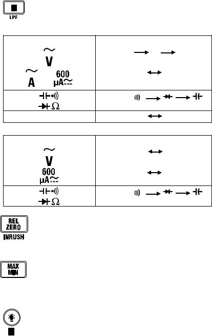
Momentary presses of the M (MODE) button perform the functions shown in the table below. Press and hold the button to activate/deactivate the Low Pass Filter
(EX655 only).
Fig. 3 4 (a) EX655 MODE Button Function Table
Switch Position |
MODE (M) Button Function |
||||||||||||||||
|
|
|
|
|
|
|
|
|
|
|
|
|
|
|
AC |
Hz |
DC |
|
|
|
|
|
|
|
|
|
|
|
|
|
|
|
|||
|
|
|
|
|
|
|
|
|
|
|
|
|
|
|
|||
|
|
|
|
|
|
|
|
|
|
|
|
|
|
|
|
|
|
|
|
|
|
|
|
or |
|
|
AC |
|
DC |
||||||
|
|
|
|
|
|
|
|
|
|||||||||
|
|
|
|
|
|
|
|
|
|
|
|||||||
|
|
|
|
|
|
|
|
|
|
||||||||
Ω 
TEMP |
oC |
oF |
Fig. 3 4 (b) EX650 MODE Button Function Table
Switch Position |
MODE (M) Button Function |
|||||||||
|
|
|
|
|
|
|
|
|
AC |
DC |
|
|
|
|
|
|
|
|
|
||
|
|
|
|
|
|
|
|
|
||
|
|
|
|
|
|
|
|
|
|
|
|
|
|
|
|
|
|
|
|
AC |
DC |
|
|
|
|
|
|
|
|
|
|
|
Ω 
Momentarily press to access/exit the Relative mode. This mode of operation is only available for DC voltage, AC Current, Resistance, and Capacitance.
In DC Mode, press to zero the display (EX655 only)
When the EX655 is in the ACA mode, press and hold to access the Inrush mode.
Press to access the MIN/MAX mode. The MAX icon will appear along with the
stored highest reading. Press again to view the minimum reading stored (MIN icon displayed). Continue to use the button in this manner as desired. Press and hold
the button to exit the MIN/MAX mode. This mode of operation is only available for AC/DC Voltage/Current, Resistance, and Temperature.
Press and hold this button to activate/deactivate the Data Hold function. Momentary presses switch the display backlight ON or OFF.
9 |
EX65x en GB_V1.6 7/16 |

Fig 3 5(a) Function Switch Description (EX655)
1.Low Impedance mode for AC Voltage
|
measurements |
7 |
||
2. |
Meter POWER OFF position |
|||
|
|
|||
3. |
AC/DC Voltage and Hz for ACV (use MODE |
6 |
||
|
button to choose AC, Hz, or DC) |
|||
4. |
Frequency mode |
|||
|
|
|||
5. |
Capacitance, Continuity, Diode, |
5 |
|
|
|
Resistance modes (use MODE button to |
|
||
|
choose mode) |
|
||
|
|
|||
6.Temperature mode
7. |
600µA AC/DC Current mode (use MODE |
4 |
|
button to choose AC or DC) |
|
8. |
AC/DC 600A Current mode (use MODE |
|
|
button to choose AC or DC) |
3 |
9. |
Non Contact Voltage Detect position with |
alert LED
Fig 3 5(b) Function Switch Description (EX650)
1. |
Low Impedance mode for AC Voltage |
|
|
|
measurements |
|
|
2. |
Meter POWER OFF position |
7 |
|
3. |
AC/DC Voltage (use MODE button to |
||
|
choose AC or DC) |
6 |
|
4. |
Capacitance, Continuity, Diode, Resistance |
||
|
modes (use MODE button to choose mode)
5.600µA AC/DC Current mode (use MODE
|
button to choose AC or DC) |
5 |
|
|
|
|
|
|
|
6. |
6A AC Current mode |
|
|
|
7. |
60A AC Current mode |
4 |
|
|
8. |
600 A AC Current mode |
|
||
|
|
|
||
9. |
Non Contact Voltage Detect position with |
|
|
|
|
alert LED |
3 |
||
|
|
|||
89
21
8 9
21
10 |
EX65x en GB_V1.6 7/16 |
4. Operation
CAUTION: Read and understand all of the Safety statements listed in the safety section of this manual prior to use.
Powering the Meter
1.Turn the rotary function switch to any position to power the meter. Check the batteries if the unit fails to power ON. Refer to the Maintenance section for battery replacement information.
2.Turn the function switch to the OFF position to power OFF the meter.
3.The meter has an Auto Power OFF sleep feature (APO) where the meter enters sleep mode after 15 minutes of inactivity. Press the Mode button to awaken the meter. When APO is enabled, the APO icon will show on the display when the meter is powered ON. To disable APO, refer to the next section.
The low battery symbol  appears on the display when the battery voltage weakens below the threshold.
Disable Auto Power OFF
The meter will enter sleep mode after 15 minutes of inactivity. Press the Mode button to awaken the meter. To defeat this feature, follow the steps below.
1.With the meter OFF, press and hold the M (MODE) button and, while continuing to hold, turn the rotary function switch to any position to power ON the meter.
2.The EX650 will beep five times indicating that APO has been disabled. The EX655 will beep two times indicating that APO has been disabled.
3.Release the button.
4.APO will now be disabled until the next cycle of power.
Display Backlight
With the meter powered ON, press and hold the backlight button  to switch the backlight ON or OFF. Note that excessive use of the backlight will shorten the battery life.
Work Light
With the meter powered ON, press and hold the Work Light button on the right side of the meter. A momentary press will switch the Work Light off. The Work Light lamp is located on the back of the unit toward the bottom of the clamp jaw. Note that excessive use of the backlight will shorten the battery life.
11 |
EX65x en GB_V1.6 7/16 |
 Loading...