


User's Guide
Pocket Autoranging DMM
Model DM220
V |
r |
AutoRanging DMM
CA V
CAT III - 1000 V |
82xxx |
|
|
CAT IV - 600 V |
|
Introduction
Congratulations on your purchase of the Extech DM220 Pocket Autoranging Multimeter. This meter measures AC/DC Voltage, AC/DC Current with 200mA/500V resettable fuse, Resistance, Capacitance, Frequency, Duty Cycle, Diode Test, and Continuity. It features a built-in non-contact AC voltage detector plus flashlight. Proper use and care of this meter will provide many years of reliable service.
Safety
|
|
|
|
|
This symbol adjacent to another symbol, terminal or |
|
|
|
|
|
operating device indicates that the operator must refer to an |
|
|
|
|
|
explanation in the Operating Instructions to avoid personal |
|
|
|
|
|
injury or damage to the meter. |
WARNING |
This WARNING symbol indicates a potentially hazardous |
||||
situation, which if not avoided, could result in death or |
|||||
|
|
|
|
|
serious injury. |
|
|
|
|
|
This symbol indicates that a device is protected throughout |
|
|
|
|
|
|
|
|
|
|
|
by double insulation or reinforced insulation. |
|
|
|
|
|
|
This meter has been designed for safe use, but must be operated with caution. The rules listed below must be carefully followed for safe operation.
1.NEVER apply voltage or current to the meter that exceeds the specified maximum:
|
Input Protection Limits |
|
Function |
|
Maximum Input |
V DC or V AC |
|
600V DC/AC |
µA AC/DC |
|
200mA 500V fast acting resettable fuse |
Resistance, Diode Test, |
|
600V DC/AC |
Continuity Test |
|
|
2.USE EXTREME CAUTION when working with voltages greater than 25VAC or 35VDC. These voltages are considered a shock hazard.
3.DO NOT measure voltage if the voltage on the "COM" input jack exceeds 600V above earth ground.
4.NEVER connect the meter leads across a voltage source while the function switch is in the current, resistance, or diode mode. Doing so can damage the meter.
5.ALWAYS discharge filter capacitors in power supplies and disconnect the power when making resistance, continuity or diode tests.
6.ALWAYS turn off the power and disconnect the test leads from the circuit before opening the cover to replace the batteries.
7.NEVER operate the meter unless the battery cover is in place and fastened securely.
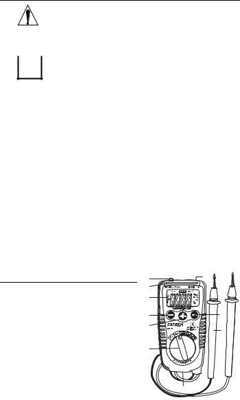
Description |
1 |
10 |
||
1. |
Non-contact ACV detector probe tip |
2 |
|
|
3 |
|
|||
2. |
Non-contact ACV indicator light |
|
||
|
|
|||
3. |
3-3/4 digit (4000 count) LCD |
4 |
9 |
|
4. |
Mode switch |
|||
5 |
|
|||
5. |
Flashlight button |
8 |
||
|
||||
6. |
Function switch |
|
|
|
7. |
Battery cover |
6 |
|
|
8. |
Test Leads |
|
|
|
9.Hz/%Duty Cycle button
10. Flashlight
7
2 |
DM220 |
V3.0 |
01/06 |

Operating Instructions
WARNING: Risk of electrocution. High-voltage circuits, both AC and DC, are very dangerous and should be measured with great care.
1.ALWAYS turn the function switch to the OFF position when the meter is not in use.
2.If “OL” appears in the display during a measurement, the value exceeds the range you have selected. Change to a higher range.
NOTE: On some low AC and DC voltage ranges, with the test leads not connected to a device, the display may show a random, changing reading. This is normal and is caused by the high-input sensitivity. The reading will stabilize and give a proper measurement when connected to a circuit.
AC/DC VOLTAGE MEASUREMENTS
CAUTION: Do not measure AC/DC voltages if a motor on the circuit is being switched ON or OFF. Large voltage surges may occur that can damage the meter.
1.Set the function switch to the V/Hz/% position.
2.Press the MODE button to indicate “AC” or “DC” on the display.
3.Touch the black test probe tip to the negative side of the circuit. Touch the red test probe tip to the positive side of the circuit.
4.Read the voltage in the display.
AC/DC CURRENT MEASUREMENTS
1.For current measurements up to 4000µA AC/DC, set the function switch to the µA position
2.For current measurements up to 200mA AC/DC, set the function switch to the mA position.
3.Press the MODE button to indicate “AC” or “DC” on the display.
4.Remove power from the circuit under test, then open up the circuit at the point where you wish to measure current.
5.Touch the black test probe tip to the negative side of the circuit. Touch the red test probe tip to the positive side of the circuit.
6.Apply power to the circuit.
7.Read the current in the display.
RESISTANCE MEASUREMENTS
WARNING: To avoid electric shock, disconnect power to the unit under test and discharge all capacitors before taking any resistance measurements. Remove the batteries and unplug the line cords.
1.Set the function switch to the Ω CAP position.
2.Press the MODE button to indicate Ω on the display.
3.Touch the test probe tips across the circuit or part under test. It is best to disconnect one side of the part under test so the rest of the circuit will not interfere with the resistance reading.
4.Read the resistance in the display.
3 |
DM220 |
V3.0 |
01/06 |

CONTINUITY CHECK
WARNING: To avoid electric shock, never measure continuity on circuits or wires that have voltage on them.
1.Set the function switch to the Ω CAP position.
2.Press the MODE button to indicate  on the display.
3.Touch the test probe tips to the circuit or wire you wish to check.
4.If the resistance is less than approximately 100Ω, the audible signal will sound. If the circuit is open, the display will indicate “OL”.
DIODE TEST
1.Set the function switch to the Ω CAP position.
2.Press the MODE button to indicate  on the display.
3.Touch the test probes to the diode under test. Forward voltage will typically indicate 0.400 to 0.700V. Reverse voltage will indicate “OL”. Shorted devices will indicate near 0V and an open device will indicate “OL” in both polarities.
CAPACITANCE MEASUREMENTS
WARNING: To avoid electric shock, disconnect power to the unit under test and discharge all capacitors before taking any capacitance measurements. Remove the batteries and unplug the line cords.
1.Set the rotary function switch to the Ω CAP position.
2.Press the MODE button to indicate nF on the display.
3.Touch the test leads to the capacitor to be tested.
4.Read the capacitance value in the display
FREQUENCY MEASUREMENTS
1.Set the rotary function switch to the V/Hz/% position.
2.Press the Hz /% button to indicate Hz on the display.
3.Touch the test probe tips to the circuit under test.
4.Read the frequency on the display.
% DUTY CYCLE
1.Set the rotary function switch to the V/Hz/% position.
2.Press the Hz/% button to select % on the display.
3.Touch the test probe tips to the circuit under test.
4.Read the % duty cycle on the display.
NON-CONTACT AC VOLTAGE DETECTOR
WARNING: Risk of electrocution. Before use, always test the Voltage Detector on a known live circuit to verify proper operation.
1.The Voltage Detector works in any function switch position, including OFF.
2.Place the detector probe tip next to the hot conductor or insert into the hot side of the electrical outlet.
3.If AC voltage is present, the detector light will illuminate.
NOTE: The conductors in electrical cord sets are often twisted. For best results, rub the probe tip along a length of the cord to assure placing the tip in close proximity to the live conductor.
NOTE: The detector is designed with high sensitivity. Static electricity or other sources of energy may randomly trip the sensor. This is normal operation.
4 |
DM220 |
V3.0 |
01/06 |

FLASHLIGHT
Press and hold the  button to turn the flashlight on. Release the button to turn the flashlight off.
AUTO POWER OFF
The auto off feature will turn the meter off after 15 minutes.
LOW BATTERY INDICATION
The  icon will appear in the lower left corner of the display when the battery voltage becomes low. Replace the battery when this appears.
Maintenance
WARNING: To avoid electric shock, disconnect the test leads from any source of voltage before removing the battery cover.
WARNING: To avoid electric shock, do not operate your meter until the battery cover is in place and fastened securely.
This MultiMeter is designed to provide years of dependable service, if the following guidelines are followed:
1.KEEP THE METER DRY. If it gets wet, wipe it off.
2.USE AND STORE THE METER IN NORMAL TEMPERATURES. Temperature extremes can shorten the life of the electronic parts and distort or melt plastic parts.
3.HANDLE THE METER GENTLY AND CAREFULLY. Dropping it can damage the electronic parts or the case.
4.KEEP THE METER CLEAN. Wipe the case occasionally with a damp cloth. DO NOT use chemicals, cleaning solvents, or detergents.
5.USE ONLY FRESH BATTERIES OF THE RECOMMENDED SIZE AND TYPE.
Remove old or weak batteries so they do not leak and damage the unit.
6.IF THE METER IS TO BE STORED FOR A LONG PERIOD OF TIME, the batteries should be removed to prevent damage to the unit.
BATTERY INSTALLATION
WARNING: To avoid electric shock, disconnect the test leads from any source of voltage before removing the battery cover.
1.Turn power off.
2.Open the rear battery cover by removing the Phillips head screw located on the bottom of the meter.
3.Insert the batteries into battery holder, observing the correct polarity.
4.Put the battery cover back in place. Secure with the screw.
WARNING: To avoid electric shock, do not operate the meter until the battery cover is in place and fastened securely.
NOTE: If your meter does not work properly, check the batteries to make sure that they are still good and that they are properly inserted.
RESETTABLE FUSE
1.The fast acting, 0.2A/500V resettable fuse will open if the current limits of the meter are exceeded.
2.The fuse will automatically reset itself when the suspect current is removed from the meter’s input.
5 |
DM220 |
V3.0 |
01/06 |
 Loading...