


User's Guide
True RMS Multimeter
Extech 430
Introduction
Congratulations on your purchase of the Extech 430 (part number EX430) True RMS Autoranging Multimeter. This meter measures AC/DC Voltage, AC/DC Current, Resistance, Capacitance, Frequency, Duty Cycle, Diode Test, and Continuity plus Thermocouple Temperature. Proper use and care of this meter will provide many years of reliable service.
Safety
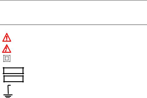
International Safety Symbols
This symbol, adjacent to another symbol or terminal, indicates the user must refer to the manual for further information.
This symbol, adjacent to a terminal, indicates that, under normal use, hazardous voltages may be present
Double insulation
WARNING
CAUTION
MAX |
600V |
This WARNING symbol indicates a potentially hazardous situation, which if not avoided, could result in death or serious injury.
This CAUTION symbol indicates a potentially hazardous situation, which if not avoided, may result damage to the product.
This symbol advises the user that the terminal(s) so marked must not be connected to a circuit point at which the voltage with respect to earth ground exceeds (in this case) 600 VAC or VDC.
2 |
EX430-EU-EN-V5.4-5/12 |
CAUTIONS
Improper use of this meter can cause damage, shock, injury or death. Read and understand this user manual before operating the meter.
Always remove the test leads before replacing the battery or fuses.
Inspect the condition of the test leads and the meter itself for any damage before operating the meter. Repair or replace any damage before use.
Use great care when making measurements if the voltages are greater than 25VAC rms or 35VDC. These voltages are considered a shock hazard.
Always discharge capacitors and remove power from the device under test before performing Diode, Resistance or Continuity tests.
Voltage checks on electrical outlets can be difficult and misleading because of the uncertainty of connection to the recessed electrical contacts. Other means should be used to ensure that the terminals are not "live".
If the equipment is used in a manner not specified by the manufacturer, the protection provided by the equipment may be impaired.
This device is not a toy and must not reach children’s hands. It contains hazardous objects as well as small parts that the children could swallow. In case a child swallows any of them, please contact a physician immediately
Do not leave batteries and packing material lying around unattended; they can be dangerous for children if they use them as toys
In case the device is going to be unused for an extended period of time, remove the batteries to prevent them from training
Expired or damaged batteries can cause cauterization on contact with the skin. Always, therefore, use suitable hand gloves in such cases
See that the batteries are not short-circuited. Do not throw batteries into the fire.
3 |
EX430-EU-EN-V5.4-5/12 |
OVERVOLTAGE CATEGORY III
This meter meets the IEC 610-1-2001 standard for OVERVOLTAGE CATEGORY III. Cat III meters are protected against overvoltage transients in fixed installation at the distribution level. Examples include switches in the fixed installation and some equipment for industrial use with permanent connection to the fixed installation.
SAFETY INSTRUCTIONS
This meter has been designed for safe use, but must be operated with caution. The rules listed below must be carefully followed for safe operation.
1.NEVER apply voltage or current to the meter that exceeds the specified maximum:
|
Input Protection Limits |
|
Function |
|
Maximum Input |
V DC or V AC |
|
1000V DC/750V AC, 200Vrms on 400mV range |
mA AC/DC |
|
500mA 250V fast acting fuse |
A AC/DC |
|
20A 250V fast acting fuse(30 seconds max every 15 |
|
|
minutes) |
Frequency, Resistance, Capacitance, |
|
250Vrms for 15sec max |
Duty Cycle, Diode Test, Continuity |
|
|
Temperature |
|
60V DC/24V AC |
2.USE EXTREME CAUTION when working with high voltages.
3.DO NOT measure voltage if the voltage on the "COM" input jack exceeds 600V above earth ground.
4.NEVER connect the meter leads across a voltage source while the function switch is in the current, resistance, or diode mode. Doing so can damage the meter.
5.ALWAYS discharge filter capacitors in power supplies and disconnect the power when making resistance or diode tests.
6.ALWAYS turn off the power and disconnect the test leads before opening the covers to replace the fuse or battery.
7.NEVER operate the meter unless the back cover and the battery and fuse covers are in place and fastened securely.
4 |
EX430-EU-EN-V5.4-5/12 |

Controls and Jacks
1.4000 count LCD display
2.HOLD
3.SELECT button
4.Function switch
5.mA, uA and A input jacks
6.COM input jack
7.Positive input jack
8.RANGE hold button
9.RELATIVE button
10.Backlight button
11.Protective holster
Note: Tilt stand and battery compartment are on rear of unit.
Symbols and Annunciators
•))) Continuity
Diode test
Battery status
Test lead connection error
n nano (10-9) (capacitance)
µmicro (10-6) (amps, cap)
m |
milli (10-3) (volts, amps) |
A |
Amps |
k |
kilo (103) (ohms) |
F |
Farads (capacitance) |
M |
mega (106) (ohms) |
|
Ohms |
Hz |
Hertz (frequency) |
V |
Volts |
% |
Percent (duty ratio) |
REL |
Relative |
AC |
Alternating current |
AUTO |
Autoranging |
DC |
Direct current |
HOLD |
Display hold |
ºF |
Degrees Fahrenheit |
ºC |
Degrees Centigrade |
5 |
EX430-EU-EN-V5.4-5/12 |
 Loading...