


User’s Manual
Mini MultiScope II
MODEL 381265

WARRANTY
EXTECH INSTRUMENTS CORPORATION warrants the basic instrument to be free of defects in parts and workmanship for one year from date of shipment (a six month limited warranty applies on sensors and cables). If it should become necessary to return the instrument for service during or beyond the warranty period, contact the Customer Service Department at (781) 890-7440 for authorization. A Return Authorization (RA) number must be issued before any product is returned to Extech. The sender is responsible for shipping charges, freight, insurance and proper packaging to prevent damage in transit. This warranty does not apply to defects resulting from action of the user such as misuse, improper wiring, operation outside of specification, improper maintenance or repair, or unauthorized modification. Extech specifically disclaims any implied warranties or merchantability or fitness for a specific purpose and will not be liable for any direct, indirect, incidental or consequential damages. Extech's total liability is limited to repair or replacement of the product. The warranty set forth above is inclusive and no other warranty, whether written or oral, is expressed or implied.
CALIBRATION AND REPAIR SERVICES
Extech offers complete repair and calibration services for all of the products we sell. For periodic calibration, NIST certification or repair of any Extech product, call customer service for details on services available. Extech recommends that calibration be performed on an annual basis to insure calibration integrity.
(
Tech Support Hotlines
781-890-7440 ext. 200 extech@extech.com
www.extech.com
Copyright © 2000 Extech Instruments Corporation.
All rights reserved including the right of reproduction in whole or in part in any form.
381265 V2.0 6/00
2
Safety
This meter has been designed to be safe in use, but the operator must use caution in its operation. The rules listed below should be carefully followed for safe operation.
1.NEVER apply voltage or current to the meter that exceeds the specified maximum for the function selected.
|
Input Limits |
|
Function |
|
Maximum Input |
V DC |
|
1000V DC |
V AC |
|
700V AC |
Ohms |
|
250V DC/AC |
mA DC/AC |
|
400mA DC/AC |
20A DC/AC |
|
20A DC/AC |
Diode |
|
250V DC/AC |
2.USE EXTREME CAUTION when working with high voltages.
3.DO NOT measure voltage if the voltage on the "COM" input jack exceeds 500V above earth ground.
4.NEVER connect the meter leads across a voltage source while the function switch is in the current, resistance or diode mode. Doing so can damage the meter.
5.ALWAYS discharge capacitors in power supplies and disconnect the power when making resistance or diode tests.
6.ALWAYS turn off the power and disconnect the test leads before opening the back to replace the fuse or batteries.
7.NEVER operate the meter unless the back cover is in place and fastened securely.
International Safety Symbols
This symbol, adjacent to another symbol or terminal, indicates the user must refer to the manual for further information.
This symbol, adjacent to a terminal, indicates that, under normal use, hazardous voltages may be present
Double insulation
3

Specifications
DIGITAL MULTIMETER
Function |
Ranges |
Resolution |
Accuracy |
|
DC Voltage |
400mV |
0.1mV |
+(0.75%rdg + 10dgt) |
|
|
4V |
1mV |
|
|
|
40V |
10mV |
|
|
|
400V |
100mV |
|
|
|
1000 V |
1V |
|
|
AC Voltage |
400mV |
0.1mV |
+(1.0%rdg + 10dgt) |
|
True RMS |
|
|
|
50Hz to 1kHz |
4V |
1mV |
|||
|
|
|
|
(unspec'd 1kHz to |
|
40V |
10mV |
||
|
|
|
|
30kHz) |
|
400V |
100mV |
|
|
|
700V |
1V |
+(1.5%rdg + 10dgt) |
|
|
|
|
|
|
DC Current |
400mA |
100μA |
+(1.2%rdg + 10dgt) |
|
|
|
|
|
|
|
20A |
10mA |
|
|
AC Current |
400mA |
100μA |
+(1.5%rdg + 10dgt) |
|
True RMS |
|
|
|
50Hz to 1kHz |
20A |
10mA |
|
||
|
|
|
||
|
|
|
|
|
Resistance |
400 ohms |
0.1 ohms |
+(3.0%rdg + 10dgt) |
|
|
|
|
|
|
|
4K |
1 ohm |
+(1.0%rdg + 5dgt) |
|
|
|
|
|
|
|
40k |
10 ohms |
|
|
|
400k |
100 ohms |
|
|
|
4Mohms |
1k ohms |
|
|
|
40Mohms |
10k ohms |
+(3.0%rdg +5dgt) |
|
|
|
|
|
|
Capacitance |
4nF |
1pF |
+(3.0%rdg + 5dgt) |
|
|
|
|
|
|
|
40nF |
10pF |
|
|
|
400nF |
100pF |
|
|
|
4μF |
1nF |
|
|
|
40μF |
10nF |
|
|
|
400μF |
100nF |
+(5.0%rdg + 10dgt) |
|
|
|
|
|
|
|
4mF |
1μF |
|
Unspecified |
Frequency |
10Hz to |
0.1Hz to |
+(1.0%rdg + 5dgt) |
|
|
100kHz |
1kHz |
|
|
Period/Pulse |
10μsec to |
1μsec to |
+(3.0%rdg + 5dgt) |
|
Width |
100msec |
0.1msec |
|
|
Duty Cycle |
1 to 100% |
1% |
+(3.0%rdg + 5dgt) |
|
|
|
|
|
|
Signal Out |
10Hz to 50kHz |
1Hz to 10kHz |
+(1.2% + 5 digits) |
|
|
|
|
|
|
|
|
4 |
|
|
Diode Test Test current of approximately 2.4mA Logic Check TTL, 3V CMOS, or 5V CMOS selectable
dB (-80 to +80dB) 2, 3, 8, 16, 50, 75, 93, 110, 125, 135, 150, 300,
|
600, 900, 1000, or 1200 ohms reference |
DIGITAL STORAGE OSCILLOSCOPE |
|
Bandwidth |
DC to 100kHz, 1 channel |
Sample rate |
1Meg samples per second |
Divisions |
+2 vertical, 9 horizontal |
Record length |
25 divisions |
Time base |
5μsec. to 1.3sec. per division |
Vertical |
75mV to 500V (17 steps) |
|
mA: 75 to 300mA (4 steps) |
|
A: 7.5 to 15A (2 steps) |
Glitch capture |
500nsec. (minimum) |
Trigger |
Level adjustable ±2 divisions (in 0.1 steps) |
|
(Positive or negative edge moving trigger) |
COMMON SPECIFICATIONS |
|
Display |
128x64 pixel graphic LCD |
Viewing Area |
2.8x1.5” (71.7x39mm) |
Measurement rateDigital: 4 times/sec. Bargraph: 7 times/sec.
Auto Power Off |
30 minutes |
Overrange |
Indicates “OVER” |
Power |
6 size AA cells, 6 size AA NiCad batteries, 3 |
|
dual cell NiCad Battery Packs or AC adaptor |
Operating time |
Alkaline (6hrs approx.), NiCad (8hrs approx.) |
|
NiCad Charging time (3hrs approx.) |
Temperature |
Operating: 32OF to 104OF (0OC to 40OC), |
|
Storage (NiCad batteries removed): -4OF to |
|
140OF (-20OC to 60OC), |
|
Charging: 32OF to 113OF (0OC to 45OC) |
Min/Max/Avg. |
Displays minimum, average, & maximum |
|
readings over time |
Hold |
Captures displayed reading |
Storage |
15 pages (text or graphics) |
Dimensions |
3.6x7.6x2.2inches (92x192x55mm) |
Weight |
1.0lbs. (450gm) |
|
5 |
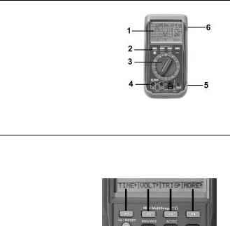
Meter Description
1.LCD Display
2.Function keys
3.Rotary range select switch
4.DMM banana input jacks
5.Protective rubber holster
6.AC Voltage adapter jack
Note: Tilt stand and battery compartment are on rear of unit.
Display Symbols and Function keys
Soft function keys F1, F2, F3, F4
These four keys perform the function indicated on the LCD display. The function will change depending on the position of the rotary switch and the mode of
operation. Functions with a right arrow will produce a sub-menu on the display for further selection.
6

OTHER FUNCTION KEYS
MODE Toggles between the multimeter text mode and the oscilloscope graphics mode. The graphics mode is available in the V, A, mV, mA and HI-A modes.
HOLD “Freezes” the reading on the display. Press “HOLD” again to resume normal operation. The symbol “HOLD” will appear on the display when Hold is
selected.
STORAGE Store and recall measurement data or graphical display.
RANGE Selects and holds a measurement range. Hold the key for 4 seconds to return to autorange mode.
Hz/RESET Press the “MODE” key for 4 seconds to select the Frequency mode in voltage functions.
MIN/MAX Press the “STORAGE” key for 4 seconds to select the MIN, MAX, Average display.
AC/DC Toggle between AC and DC measurements in mV, mA and A functions.
BASIC DISPLAYS
Refer to illustrations below. The Oscilloscope mode produces a graphical display (left). The Multimeter mode produces a numerical display with an analog bargraph (right).
7
 Loading...