


 Loading...
User Guide
FVA-3150
Variable Attenuator

Copyright © 2010–2011 EXFO Inc. All rights reserved. No part of this publication may be reproduced, stored in a retrieval system or transmitted in any form, be it electronically, mechanically, or by any other means such as photocopying, recording or otherwise, without the prior written permission of EXFO Inc. (EXFO).
Information provided by EXFO is believed to be accurate and reliable. However, no responsibility is assumed by EXFO for its use nor for any infringements of patents or other rights of third parties that may result from its use. No license is granted by implication or otherwise under any patent rights of EXFO.
EXFO’s Commerce And Government Entities (CAGE) code under the North Atlantic Treaty Organization (NATO) is 0L8C3.
The information contained in this publication is subject to change without notice.
Trademarks
EXFO’s trademarks have been identified as such. However, the presence or absence of such identification does not affect the legal status of any trademark.
Units of Measurement
Units of measurement in this publication conform to SI standards and practices.
Version number: 1.0.0
ii |
FVA-3150 |

|
Contents |
Contents |
|
Certification Information ........................................................................................................ |
v |
1 Introducing the FVA-3150 Variable Attenuator .......................................... |
1 |
Main Features ......................................................................................................................... |
1 |
Front Panel ............................................................................................................................. |
2 |
Back Panel .............................................................................................................................. |
3 |
Available Models .................................................................................................................... |
4 |
Typical Applications ................................................................................................................ |
4 |
Main Concept ......................................................................................................................... |
5 |
Conventions ............................................................................................................................ |
6 |
2 Safety Information ....................................................................................... |
7 |
Laser Safety Information ......................................................................................................... |
7 |
Electrical Safety Information ................................................................................................... |
8 |
3 Getting Started With Your Variable Attenuator ....................................... |
11 |
Installing your FVA-3150 Variable Attenuator in a Rackmount ............................................. |
11 |
Turning the Variable Attenuator On and Off ......................................................................... |
13 |
Accessing Menus .................................................................................................................. |
14 |
4 Setting Up Your Variable Attenuator ........................................................ |
15 |
Selecting the Display Intensity .............................................................................................. |
15 |
Locking Control Key Access ................................................................................................... |
16 |
Managing the Wavelength Shortlist ..................................................................................... |
17 |
Selecting the Attenuation ..................................................................................................... |
20 |
Selecting and Using an Attenuation Display Mode ............................................................... |
24 |
Saving and Recalling a Configuration ................................................................................... |
31 |
5 Operating Your Variable Attenuator ......................................................... |
35 |
Cleaning and Connecting Optical Fibers ............................................................................... |
35 |
Installing the EXFO Universal Interface (EUI) ......................................................................... |
37 |
Performing an Attenuation Routine ...................................................................................... |
38 |
Operating the Shutter ........................................................................................................... |
44 |
Variable Attenuator |
iii |

Contents |
|
|
6 |
Controlling Your Variable Attenuator Remotely |
.......................................45 |
|
Setting Up the Variable Attenuator for Remote Control ....................................................... |
45 |
|
Communication Parameters .................................................................................................. |
48 |
|
Standard Status Data Structure ............................................................................................ |
49 |
|
Command Structure ............................................................................................................. |
51 |
|
Error Messages ..................................................................................................................... |
52 |
|
SCPI Management Errors (System Errors) .............................................................................. |
53 |
|
RS-232 Connector Pinout ...................................................................................................... |
54 |
7 |
Maintenance ................................................................................................ |
55 |
|
Cleaning EUI Connectors ...................................................................................................... |
56 |
|
Cleaning Detector Ports ........................................................................................................ |
58 |
|
Recalibrating the Unit ........................................................................................................... |
59 |
|
Recycling and Disposal (Applies to European Union Only) .................................................... |
60 |
8 |
Troubleshooting .......................................................................................... |
61 |
|
Contacting the Technical Support Group .............................................................................. |
61 |
|
Transportation ...................................................................................................................... |
62 |
9 |
Warranty ...................................................................................................... |
63 |
|
General Information ............................................................................................................. |
63 |
|
Liability ................................................................................................................................. |
64 |
|
Exclusions ............................................................................................................................. |
65 |
|
Certification .......................................................................................................................... |
65 |
|
Service and Repairs ............................................................................................................... |
66 |
|
EXFO Service Centers Worldwide .......................................................................................... |
67 |
A |
Technical Specifications .............................................................................. |
69 |
B |
Remote Control Commands ....................................................................... |
71 |
|
IEEE 488.2 Required Commands ........................................................................................... |
71 |
|
Specific commands-Quick Reference Command Tree ............................................................ |
79 |
Index ............................................................................................................... |
103 |
|
iv |
FVA-3150 |

Certification Information
Certification Information
FCC Information
Electronic test equipment is exempt from Part 15 compliance (FCC) in the United States. However, compliance verification tests are systematically performed on most EXFO equipment.
Information
Electronic test equipment is subject to the EMC Directive in the European Union. The EN61326 standard prescribes both emission and immunity requirements for laboratory, measurement, and control equipment.
This unit has undergone extensive testing according to the European Union Directive and Standards.
CSA Information
This unit is certified by the CSA (certificate number 162451) and was evaluated according to applicable CSA and UL standards (as confirmed by “C-US” mark) as well as applicable IEC standards for use in Canada, the United States, and other countries.
Variable Attenuator |
v |

Certification Information
 DECLARATION OF CONFORMITY
Application of Council Directives: |
2006/95/EC - The Low Voltage Directive |
|
2004/108/EC - The EMC Directive |
|
2006/66/EC - The Battery Directive |
|
93/68/EEC - CE Marking |
|
And their amendments |
Manufacturer’s Name: |
EXFO Inc. |
Manufacturer’s Address: |
400 Godin Avenue |
|
Quebec, Quebec |
|
Canada, G1M 2K2 |
Equipment Type/Environment: |
Test & Measurement / Industrial |
Trade Name/Model No.: |
Variable Attenuator / FVA-3150 |
Standard(s) to which Conformity is Declared:
EN 61010-1:2001 Edition 2.0 |
Safety Requirements for Electrical Equipment for Measurement, |
|
Control, and Laboratory Use – Part 1: General Requirements. |
EN 61326-1:2006 |
Electrical Equipment for Measurement, Control and Laboratory |
|
Use - EMC Requirements |
EN 55022: 2006 + A1: 2007 |
Information technology equipment — Radio disturbance |
|
characteristics — Limits and methods of measurement |
I, the undersigned, hereby declare that the equipment specified above conforms to the above Directives and Standards.
Manufacturer
Signature:
Full Name: |
Stephen Bull, E. Eng |
Position: |
Vice-President Research and |
|
Development |
Address: |
400 Godin Avenue, Quebec (Quebec), |
|
Canada, G1M 2K2 |
Date: |
June 2, 2010 |
vi |
FVA-3150 |

1Introducing the FVA-3150 Variable Attenuator
Main Features
The FVA-3150 Variable Attenuator is the instrument that allows you to perform several attenuation related tasks.
The FVA-3150 Variable Attenuator is configured for singlemode and multimode fibers. It is built to offer a high spectral uniformity, an important feature which allows you to maintain the attenuation value throughout the entire WDM spectrum. Its low insertion loss allows you to minimize your loss budget.
The FVA-3150 Variable Attenuator has a program function, which allows you to create custom programs such as automatic attenuation scan.
The Variable Attenuator has the versatility of three display modes:
Absolute, which includes the insertion loss.
Reference, in reference to the 0.001 dB level.
Offset, relative display to any selected reference value.
The FVA-3150 Variable Attenuator is controlled by easy-to-use software, enabling multiple-user configuration storage.
The FVA-3150 Variable Attenuator can be remotely controlled through a GPIB or RS-232 interface.
Variable Attenuator |
1 |

Introducing the FVA-3150 Variable Attenuator
Front Panel
Front Panel
Program menu access
|
|
|
Setup menu access |
Confirmation |
||
|
|
Display |
|
|
button (Enter) |
|
|
|
|
|
|
||
|
Shutter control |
|
|
|
Arrow buttons for |
|
Absolute mode access |
|
|
|
|
menu navigation and |
|
|
|
|
|
parameter setting |
||
|
|
|
|
|
Program |
|
|
|
|
|
|
|
ENTER |
|
|
Step |
|
|
|
Setup |
|
|
|
|
|
|
|
Abs |
Offset |
Up |
Shutter |
|
|
|
|
Ref |
Down |
Attenuation |
In |
Monitor |
Out |
On/off button |
|
|
|
|
|
Output port |
Wavelength control |
|
|
|
Monitor port |
||
|
|
|
|
|
(BM and DM models only) |
|
Reference mode access |
|
|
|
Input port |
|
|
|
|
|
|
|
|
|
Offset mode access |
|
|
|
|
|
|
|
Attenuation controls |
|
|
|
||
Note: Your FVA-3150 Variable Attenuator may differ slightly from the illustration depending on the specific model of your unit.
2 |
FVA-3150 |

Introducing the FVA-3150 Variable Attenuator
Back Panel
Back Panel
Serial port (RS-232 DTE) |
Fuse holder |
GPIB port |
Power inlet |
GPIB IEEE 488.2 |
Serial Port |
MODEL: GO |
|
|
R LR107723 |
|
C |
US |
100-240 V 50/60 Hz
2 A
 F2AL250 V
SH1, AH1, T6, L4, SR1, RL1, PP0, DC1, DT1, C0, E2
This device complies with part 15 of the FCC rules. Operation is subject to the following two conditions: (1) this device may not cause harmful interference and (2) this device must accept any interference received, including interference that may cause undesired operation.
P/N |
|
Ver. |
|
|
|
S/N |
|
Mfg. |
|
date |
Made in Canada QST-151F
Electro-Optical Engineering
465 Godin Avenue
Vanier QC G1M 3G7 Canada
|
|
|
|
|
|
|
|
|
|
|
|
|
|
|
|
|
Ground |
Part number |
|
|
P/N |
|
|
|
|
|
|
|
|
Version number |
|||||
|
|
FVA-3150-B-EI |
A-1.0 |
|
|
|
Ver. |
|
|
Spectral range |
|||||||
Fiber type |
|
|
|
|
|
9/125 µM |
1200 TO 1650 NM |
|
|
|
|
|
|
|
|||
|
S/N |
|
Mfg. |
||||||||||||||
|
|
|
|
12345-AB |
JANUARY 2010 |
|
|
|
Manufacturing date |
||||||||
Serial number |
|
|
|
|
|
|
|
date |
|
|
|
||||||
|
|
|
|
|
|
|
|
|
|
|
|
|
|
|
|
|
|
Note: Your FVA-3150 Variable Attenuator may differ slightly from the illustration depending on the specific model of your unit.
Variable Attenuator |
3 |

Introducing the FVA-3150 Variable Attenuator
Available Models
Available Models
According to the models you own, additional options are available. The FVA-3150-CM, FVA-3150-BM, and FVA-3150-DM all come with a monitor output, which ensures accurate power-level monitoring.
Typical Applications
The FVA-3150 Variable Attenuator is ideal for:
manufacturing and laboratory applications such as system characterization
EDFA
component and system loss simulation
instrument calibration
power meter linearity measurement
spectral tuning
The FVA-3150 Variable Attenuator is particularly suitable to demanding laboratory and manufacturing qualification applications.
4 |
FVA-3150 |
Introducing the FVA-3150 Variable Attenuator
Main Concept
Main Concept
The significance of the attenuation value displayed by an optical attenuator may differ from one manufacturer to another. At EXFO, for example, the attenuation displayed by the FVA-3150 Variable Attenuator is the actual loss or attenuation between the input and the output ports of the Variable Attenuator, including the loss of its own internal connectors, after performing a reference reading with a power meter.
IMPORTANT
The Variable Attenuator has been calibrated with a light source connected to the input port and a power meter connected to the output port. For optimum performance, do not interchange the input and output connections.
Variable Attenuator |
5 |

Introducing the FVA-3150 Variable Attenuator
Conventions
Conventions
Before using the product described in this manual, you should understand the following conventions:
WARNING
Indicates a potentially hazardous situation which, if not avoided, could result in death or serious injury. Do not proceed unless you understand and meet the required conditions.
CAUTION
Indicates a potentially hazardous situation which, if not avoided, may result in minor or moderate injury. Do not proceed unless you understand and meet the required conditions.
CAUTION
Indicates a potentially hazardous situation which, if not avoided, may result in component damage. Do not proceed unless you understand and meet the required conditions.
IMPORTANT
Refers to information about this product you should not overlook.
6 |
FVA-3150 |

2 Safety Information
Laser Safety Information
WARNING
Do not install or terminate fibers while a light source is active. Never look directly into a live fiber and ensure that your eyes are protected at all times.
WARNING
Use of controls, adjustments and procedures for operation and maintenance other than those specified herein may result in hazardous radiation exposure or impair the protection provided by this unit.
Variable Attenuator |
7 |

Safety Information
Electrical Safety Information
Electrical Safety Information
This unit uses an international safety standard three-wire power cable. This cable serves as a ground when connected to an appropriate AC power outlet.
Note: If you need to ensure that the unit is completely powered off, disconnect the power cable.
WARNING
Insert the power cable plug into a power outlet with a protective ground contact. Do not use an extension cord without a protective conductor.
Before powering on the unit, connect all grounding terminals, extension cords and devices to a protective ground via a ground socket. Any interruption of the protective grounding is a potential shock hazard and may cause personal injury. Whenever the ground protection is impaired, do not use the unit and secure it against any accidental operation.
Do not tamper with the protective ground terminal.
The color coding used in the electric cable depends on the cable. New plugs should meet the local safety requirements and include:
adequate load-carrying capacity
ground connection
cable clamp
IMPORTANT
EXFO assumes no liability if you attempt to perform internal service on this unit.
8 |
FVA-3150 |

Safety Information
Electrical Safety Information
WARNING
Use this unit indoors only.
Position the unit so that the air can circulate freely around it.
Operation of any electrical instrument around flammable gases or fumes constitutes a major safety hazard.
Do not remove unit covers during operation.
To avoid electrical shock, do not operate the unit if any part of the outer surface (covers, panels, etc.) is damaged.
Only authorized personnel should carry out adjustments, maintenance or repair of opened units under voltage. A person qualified in first aid must also be present. Do not replace any components while power cable are connected.
Use only fuses with the required rated current and specified type (IEC, 5 mm x 20 mm (0.197 in x 0.787 in), fast-blow, 250 V, 2 A). Do not use repaired fuses or short-circuited fuse holders.
Capacitors inside the unit may be charged even if the unit has been disconnected from its electrical supply.
Variable Attenuator |
9 |

Safety Information
Electrical Safety Information
|
Equipment Ratings |
|
|
|
|
|
|
|
Temperature |
|
|
Operation |
|
0 °C to 40 °C (32 °F to 104 °F) |
Storage |
|
-40 °C to 70 °C (-40 °F to 158 °F) |
|
|
|
Relative humiditya |
|
0 % to 80 % non-condensing |
Maximum operation altitude |
|
2000 m (6562 ft) |
|
|
|
Pollution degree |
|
2 |
|
|
|
Overvoltage category |
|
II |
|
|
|
Power supply ratingb |
|
100 V to 240 V (50 Hz/60 Hz) |
|
|
maximum input power 2 A |
|
|
|
a.Measured in 0 °C to 31 °C (32 °F to 87.8 °F) range, decreasing linearly to 50 % at 40 °C (104 °F).
b.Not exceeding ± 10 % of the nominal voltage.
The following label is located on the back panel of the unit:
10 |
FVA-3150 |

3Getting Started With Your Variable Attenuator
Installing your FVA-3150 Variable Attenuator in a Rackmount
You can place your FVA-3150 Variable Attenuator in a rackmount to facilitate its usage.
To install the rackmount:
1. Fix the angle iron using four flat Phillips screws.
 3
3


 2
2
4


 1
1

2.Fix the rackmount bracket to the frame using two round Phillips screws.
3.Fix the rackmount stiffener using two flat Phillips screws (for the front panel) and two round Phillips screws.
4.If your rackmount will contain only one unit, fix the rackmount cover plate to the empty part of the frame using four flat Phillips screws.
Variable Attenuator |
11 |

Getting Started With Your Variable Attenuator
Installing your FVA-3150 Variable Attenuator in a Rackmount
To install your FVA-3150 Variable Attenuator in a rackmount:
1.Slide the benchtop unit into the rackmount and tighten it from underneath using the four cover fixing screws.
If measurement X on the illustration exceeds 11.125 in., fix the unit into the four holes identified as A. Otherwise, use the other four holes.
X
A
2.If a second benchtop is to be installed, remove the cover plate and repeat step 1.
12 |
FVA-3150 |

Getting Started With Your Variable Attenuator
Turning the Variable Attenuator On and Off
Turning the Variable Attenuator On and Off
When you turn on your unit:
it beeps twice
it performs a self-test
it enters the mode that was active at the last power-off (Absolute, Offset, or Reference)
When you turn the unit off, the following items remain in read-only memory:
current shutter state
current display mode
current attenuation setting
current wavelength
shortlisted wavelengths
each wavelength offsets
step size
remote-control settings
programmed attenuation routine settings
saved configurations
Note: The power cord is the most effective disconnecting device. To ensure that the power is completely turned off, disconnect the power cord.
Variable Attenuator |
13 |

Getting Started With Your Variable Attenuator
Accessing Menus
To turn the unit on and off:
Use the red button in the lower left corner of the front panel.
IMPORTANT
Some internal mechanisms can sometimes take a few seconds to adjust, depending on the operation performed. While the Variable Attenuator is performing internal adjustments (for example after having changed the wavelength or the attenuation setting), no buttons should be pressed while Program flashes on the display.
CAUTION
The Variable Attenuator should not be turned off while Program is flashing in the lower left corner of the display.
Accessing Menus
The blue buttons to the right of the display give access to single-level menus: Program and Setup. The following diagram shows the menus and their items.
|
|
|
|
|
|
|
|
|
|
|
|
|
|
|
|
|
|
|
|
|
|
|
|
|
|
|
|
|
|
|
|
|
|
|
|
|
|
|
|
|
|
|
|
|
|
|
|
|
Delay |
|
|
|
Duration |
|
|
|
Step |
|
|
|
|
ATT. |
|
Start |
|
|
|
Stop |
|
|
Exit |
|
|
|
|
|
|
||||||||||||||||
Program |
|
|
|
|
|
|
|
|
|
|
|
|
|
|
|
|
|
|
|
|
|
|
|
|
|
|
|
|
|
|
|
|
|
|
|
|
|
|
|
|
|
|
|
|||
|
|
|
|
|
|
|
|
|
|
|
|
|
|
|
|
|
|
|
|
|
|
|
|
|
|
|
|
|
|
|
|
|
|
|
|
|
|
|
|
|
|
|
||||
|
|
|
|
|
|
|
|
|
|
|
|
|
|
|
|
|
|
|
|
|
|
|
|
|
|
|
|
|
|
|
|
|
|
|
|
|
|
|
|
|
|
|||||
|
|
|
|
|
|
|
|
|
|
|
|
|
|
|
|
|
|
|
|
|
|
|
|
|
|
|
|
|
|
|
|
|
|
|
|
|
|
|
|
|
|
|||||
|
Step |
|
|
|
|
Lambda |
|
|
|
|
Offset |
|
|
|
Dimmer |
|
|
|
|
GPIB-RS |
|
|
|
|
|
Save |
|
|
|
Recall |
|
|
|
Lockout |
Exit |
|||||||||||
|
|
|
|
|
|
|
|
|
|
|
|
|
|
|
|
|
|
|
|
|
|
|
|
|
|
|
|
|
|
|
|
|
|
|
|
|
|
|
|
|
|
|
|
|
||
Setup |
|
|
|
|
|
|
|
|
|
|
|
|
|
|
|
|
|
|
|
|
|
|
|
|
|
|
|
|
|
|
|
|
|
|
|
|
|
|
|
|
|
|
|
|
||
|
|
|
|
|
|
|
|
|
|
|
|
|
|
|
|
|
|
|
|
|
|
|
|
|
|
|
|
|
|
|
|
|
|
|
|
|
|
|
|
|
|
|||||
To move (in a loop) between the menu items:
Use the left/right arrows.
To exit a menu:
Press the button that gave access to the menu; OR
Use the left/right arrows to move until EXIT is displayed, then press ENTER.
14 |
FVA-3150 |
4Setting Up Your Variable Attenuator
Selecting the Display Intensity
Display intensity may be set to high or low. You can also turn off the display without turning off the unit.
To select the display intensity:
1.Press the Setup button.
2.Use the left/right arrows to move until it displays DIMMER.
3.Press ENTER. The current dimmer state will start flashing.
4.Use the up/down arrows to modify the dimmer status: LO, HI, or OFF.
5.Press ENTER.
Note: Setting the dimmer to OFF turns off the display. Press any button to turn the display back on.
6. To exit the Setup menu, press the Setup button.
Variable Attenuator |
15 |

Setting Up Your Variable Attenuator
Locking Control Key Access
Locking Control Key Access
To prevent unintended use of the FVA-3150 Variable Attenuator during operation, you can lock the control keys (the blue buttons on the front panel of the unit).
To lock the control key access:
1.Press the Setup button.
2.Use the left/right arrows until LOCKOUT is displayed.
3.Press ENTER.
The LOCKED message is briefly displayed, then the unit reverts to the settings that were active before you entered the Setup menu. All control keys are deactivated.
To unlock the keypad:
1.Press the Setup button.
2.Press ENTER.
The UNLOCKED message is briefly displayed. All control keys are reactivated.
16 |
FVA-3150 |

Setting Up Your Variable Attenuator
Managing the Wavelength Shortlist
Managing the Wavelength Shortlist
The FVA-3150 Variable Attenuator can test at many wavelengths. The accepted wavelengths depend on the configuration of your unit. You can store the wavelengths you use most often in a shortlist so you can quickly access them. The shortlist includes up to 20 wavelengths.
Note: When switching to a new wavelength, the attenuator motor will reposition itself to keep the current attenuation value for the new wavelength.
Refer to Technical Specifications on page 69 for more information on the wavelength ranges that you can enter.
Variable Attenuator |
17 |

Setting Up Your Variable Attenuator
Managing the Wavelength Shortlist
To add a wavelength to the shortlist:
1.Press the Setup button.
2.Use the left/right arrows to move until LAMBDA is displayed.
nm
3.Use the up/down arrows to move until Add is displayed .
4.Press ENTER. A wavelength will be suggested and the first digit will flash.
5.Use the up/down arrows to change the flashing digit and the left/right arrows to activate the next digit.
6.Once all digits are set, press ENTER.
7.To exit the Setup menu, press the Setup button.
Note: If you are trying to enter a wavelength that is outside the wavelength range, the Variable Attenuator will beep and reject the wavelength.
18 |
FVA-3150 |

Setting Up Your Variable Attenuator
Managing the Wavelength Shortlist
To delete a wavelength from the shortlist:
1.Press the Setup button.
2.Press the left/right arrows until LAMBDA is displayed.
3.Use up/down arrows to move until the wavelength you want to delete appears in the lower portion of the display.
4.Press ENTER. The wavelength will start flashing.
5.Set all the wavelength digits to zero. To do so, use the up/down arrows to change the flashing digit and the left/right arrows to activate the next digit.
6.Press ENTER.
7.To exit the Setup menu, press the Setup button.
To delete all wavelengths from the shortlist:
1.Press the Setup button.
2.Press the left/right arrows until LAMBDA is displayed.
3.Press the up/down arrows until DEL ALL appears in the lower portion of the display.
4.Press ENTER.
Variable Attenuator |
19 |
Setting Up Your Variable Attenuator
Selecting the Attenuation
Selecting the Attenuation
The attenuation can be set using two methods:
By using the up and down arrows buttons, the attenuation is modified one step (up or down) at a time.
By using the Attenuation button, you can quickly and precisely set the attenuation to a specific value
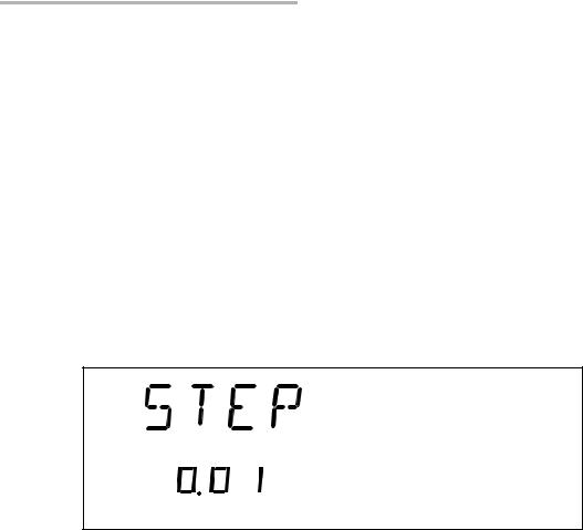
The available step sizes are: 0.01, 0.02, 0.05, 0.1, 0.2, 0.5, 1, 2, 5, 10, 20, and 50 dB.
Note: Selecting a larger step size allows for faster attenuation scanning.
To change the step size:
1.Press the Setup button.
2.Press the left/right arrows until STEP is displayed.
3.Press ENTER. The current step size will start flashing.
4.Using the up/down arrows, select one of the available step sizes.
5.Press ENTER.
6.To exit the Setup menu, press the Setup button.
20 |
FVA-3150 |

Setting Up Your Variable Attenuator
Selecting the Attenuation
To enter a specific attenuation value:
1.Press the Attenuation button. The first segment of the attenuation setting starts flashing.
Attenuation setting
dB
Abs
nm
Current wavelength
2.Enter a new attenuation value. Use the up/down arrows to change the flashing digit and the left/right arrows to activate the next digit.
Note: The difference with the current attenuation must be of at least 0.002 dB for the new attenuation setting to be valid. For more information on the variable attenuator optical resolution see Technical Specifications on page 69.
3. Once you have entered all the segments, press ENTER.
Note: If you try to set an attenuation value that is outside the attenuation range, the Variable Attenuator will default to the minimum or maximum setting.
The attenuation range (minimum and maximum possible attenuation) of your FVA-3150 Variable Attenuator depends on the model you have at hand. Although EXFO guarantees that the minimum insertion loss is below a specified value, it may vary slightly from one wavelength to another and from one variable attenuator to another.
Variable Attenuator |
21 |

Setting Up Your Variable Attenuator
Selecting the Attenuation
To set the minimum attenuation:
1.Select a wavelength, by pressing until you reach the desired wavelength.
Program
ENTER
|
|
|
|
|
|
Step |
|
|
|
|
|
|
|
|
|
Setup |
|||
|
|
|
|
|
|
|
|
|
|
|
|
|
|
|
|
|
|
|
|
|
|
Abs |
|
Offset |
Up |
|
|
|
Shutter |
|
|
|
|
|
|
|
|
|
|
|
|
|
|
|
|
|
|
|
|
|
|
|
|
|
|||||
|
|
|
|
|
|
|
|
|
|
|
|
In |
|
Monitor |
|
|
Out |
||
|
|
|
|
|
|
|
|
|
|
|
|
|
|
||||||
|
|
|
|
Ref |
Down |
|
|
Attenuation |
|
|
|
|
|||||||
|
|
|
|
|
|
|
|
|
|
|
|
|
|
|
|
|
|
|
|
Wavelength control |
|
|
|
|
|
|
Attenuation |
|
|
|
|
|
|
|
|
|
|||
|
|
|
|
|
|
|
|
|
|
|
|
|
|
||||||
Absolute mode access
2.Press the Abs button.
3.Press the Attenuation button and set an attenuation of 00.000 dB.
4.Press ENTER. The Variable Attenuator will default to the minimum insertion loss.
22 |
FVA-3150 |

Setting Up Your Variable Attenuator
Selecting the Attenuation
To set the maximum attenuation:
1.Select a wavelength by pressing until you reach the desired wavelength.
2.Press the Abs button.
3.Press the Attenuation button and set an attenuation of -99.999 dB.
4.Press ENTER. The Variable Attenuator will default to the maximum attenuation.
Variable Attenuator |
23 |

Setting Up Your Variable Attenuator
Selecting and Using an Attenuation Display Mode
Selecting and Using an Attenuation Display
Mode
Note: The total or absolute attenuation referred to in this manual is the actual optical insertion loss between the input and output ports, including the connectors.
The Variable Attenuator offers the following three attenuation display modes:
Absolute attenuation mode
Offset attenuation mode
Reference attenuation mode
Display Mode |
Description |
|
|
|
|
Absolute |
The displayed attenuation value takes into account both |
|
the absolute value and the offset value. |
|
Default mode upon initial activation. |
|
|
Reference |
The displayed attenuation value is the attenuation relative |
(relative) |
to a defined reference value, which can be any value |
|
within the unit’s attenuation range and may be selected as |
|
the reference. |
|
|
24 |
FVA-3150 |
Loading...