


 Loading...
User Guide
FOT-930
Multifunction Loss Tester

Copyright © 2004–2013 EXFO Inc. All rights reserved. No part of this publication may be reproduced, stored in a retrieval system or transmitted in any form, be it electronically, mechanically, or by any other means such as photocopying, recording or otherwise, without the prior written permission of EXFO Inc. (EXFO).
Information provided by EXFO is believed to be accurate and reliable. However, no responsibility is assumed by EXFO for its use nor for any infringements of patents or other rights of third parties that may result from its use. No license is granted by implication or otherwise under any patent rights of EXFO.
EXFO’s Commerce And Government Entities (CAGE) code under the North Atlantic Treaty Organization (NATO) is 0L8C3.
The information contained in this publication is subject to change without notice.
Trademarks
EXFO’s trademarks have been identified as such. However, the presence or absence of such identification does not affect the legal status of any trademark.
Units of Measurement
Units of measurement in this publication conform to SI standards and practices.
Version number: 8.0.0
ii |
FOT-930 |

|
Contents |
Contents |
|
Certification Information ....................................................................................................... |
vi |
1 Introducing the FOT-930 Multifunction Loss Tester ................................... |
1 |
Main Features ......................................................................................................................... |
1 |
Power Sources ........................................................................................................................ |
4 |
Typical Applications ................................................................................................................ |
4 |
Conventions ............................................................................................................................ |
5 |
2 Safety Information ....................................................................................... |
7 |
Other Safety Symbols on Your Unit ......................................................................................... |
8 |
Laser Safety Information (Units without VFL) .......................................................................... |
9 |
Laser Safety Information (Units with VFL) ............................................................................... |
9 |
Electrical Safety Information ................................................................................................. |
10 |
3 Getting Started with Your Multifunction Loss Tester .............................. |
13 |
Turning the Unit On and Off ................................................................................................. |
13 |
Using Menus and Keypad ..................................................................................................... |
14 |
4 Customizing Your Multifunction Loss Tester ............................................ |
17 |
Selecting the Language of Operation ................................................................................... |
17 |
Setting the Date and Time .................................................................................................... |
18 |
Adjusting the Brightness and Contrast ................................................................................. |
19 |
Activating and Setting Screen Saver and Auto-Off ................................................................ |
20 |
5 Setting Up Your Multifunction Loss Tester ............................................... |
21 |
Installing the EXFO Universal Interface (EUI) ......................................................................... |
21 |
Cleaning and Connecting Optical Fibers ............................................................................... |
22 |
Setting Autonaming Scheme ................................................................................................ |
24 |
Setting Pass/Fail Thresholds .................................................................................................. |
26 |
6 Measuring Power or Loss .......................................................................... |
29 |
Defining the List of Favorite Wavelengths ............................................................................. |
30 |
Nulling Electrical Offsets ....................................................................................................... |
32 |
Referencing Your Power Meter to a Source ........................................................................... |
33 |
Measuring Power or Loss ...................................................................................................... |
36 |
Automatically Detecting Wavelength .................................................................................... |
39 |
7 Measuring Optical Return Loss ................................................................. |
41 |
Performing ORL Reference and Setting ORL Zero Value ........................................................ |
42 |
Performing and Saving ORL Measurements .......................................................................... |
43 |
Multifunction Loss Tester |
iii |

Contents |
|
8 Performing Automated IL/ORL/Length Measurements (FASTEST) ............... |
47 |
Setting Up the FASTEST ........................................................................................................ |
48 |
Referencing Units for FASTEST ............................................................................................. |
49 |
Performing the FASTEST ....................................................................................................... |
52 |
9 Managing Test Results ................................................................................ |
55 |
Viewing and Deleting Results ............................................................................................... |
55 |
Checking Available Memory .................................................................................................. |
56 |
Transferring Test Results to a Computer ................................................................................ |
56 |
10 Using a Light Source ................................................................................... |
59 |
11 Identifying Fiber Faults Visually ................................................................ |
61 |
12 Inspecting Fibers with the FIP .................................................................... |
63 |
13 Communicating with Other Users ............................................................. |
65 |
Sending and Receiving Text Messages .................................................................................. |
65 |
Communicating by Voice ...................................................................................................... |
68 |
14 Maintenance ................................................................................................ |
71 |
Cleaning EUI Connectors ...................................................................................................... |
71 |
Cleaning Detector Ports ........................................................................................................ |
74 |
Cleaning VFL-Type Connectors .............................................................................................. |
75 |
Recharging Main Batteries .................................................................................................... |
76 |
Replacing Batteries ............................................................................................................... |
77 |
Battery Safety Information .................................................................................................... |
78 |
Recalibrating the Unit ........................................................................................................... |
79 |
Upgrading the Embedded Software ..................................................................................... |
80 |
Recycling and Disposal (Applies to European Union Only) .................................................... |
80 |
15 Troubleshooting .......................................................................................... |
81 |
Solving Common Problems ................................................................................................... |
81 |
Obtaining Online Help .......................................................................................................... |
85 |
Contacting the Technical Support Group .............................................................................. |
86 |
Transportation ...................................................................................................................... |
87 |
16 Warranty ...................................................................................................... |
89 |
General Information ............................................................................................................. |
89 |
Liability ................................................................................................................................. |
90 |
Exclusions ............................................................................................................................. |
90 |
Certification .......................................................................................................................... |
90 |
Service and Repairs ............................................................................................................... |
91 |
EXFO Service Centers Worldwide .......................................................................................... |
92 |
iv |
FOT-930 |

|
Contents |
A Technical Specifications |
............................................................................. 93 |
Index ................................................................................................................ |
95 |
Multifunction Loss Tester |
v |

Certification Information
Certification Information
North America Regulatory Statement
This unit was certified by an agency approved in both Canada and the United States of America. It has been evaluated according to applicable North American approved standards for product safety for use in Canada and the United States.
Electronic test and measurement equipment is exempt from FCC part 15, subpart B compliance in the United States of America and from ICES-003 compliance in Canada. However, EXFO Inc. makes reasonable efforts to ensure compliance to the applicable standards.
The limits set by these standards are designed to provide reasonable protection against harmful interference when the equipment is operated in a commercial environment. This equipment generates, uses, and can radiate radio frequency energy and, if not installed and used in accordance with the user guide, may cause harmful interference to radio communications. Operation of this equipment in a residential area is likely to cause harmful interference in which case the user will be required to correct the interference at his own expense.
Modifications not expressly approved by the manufacturer could void the user's authority to operate the equipment.
vi |
FOT-930 |

Certification Information
DECLARATION OF CONFORMITY
Application of Council Directive(s): |
1999/5/EC – The R&TTE Directive |
|
|
2011/65/UE – Restriction of the use of certain hazardous substances (RoHS) |
|
|
And their amendments |
|
Manufacturer’s Name and Address: |
EXFO Inc. |
EXFO Europe Ltd. |
|
400 Godin Avenue |
Winchester House |
|
Quebec City, Quebec |
School Lane, Chandlers Ford |
|
G1M 2K2, CANADA |
SO53 4DG, UK |
|
Tel.: +1 418 683-0211 |
Tel.: +44 2380 246 800 |
Equipment Type/Environment: |
Test & Measurement / Industrial |
|
Trade Name/Model No.: |
Multifunction Loss Tester—FOT-930 MaxTester |
|
Standard(s) to which Conformity is declared:
EN 61010-1:2010 Edition 3.0
EN 61326-1:2006
EN 60825-1:2007 Edition 2.0
Safety requirements for electrical equipment for measurement, control, and laboratory use – Part 1: General requirements
Electrical equipment for measurement, control and laboratory use – EMC requirements – Part 1: General requirements
Safety of laser products – Part 1: Equipment classification and requirements
I, the undersigned, hereby declare that the equipment specified above conforms to the above Directive and Standards.
Manufacturer:
Stephen Bull, E. Eng
Vice-President Research and Development
400 Godin Avenue,
Quebec City, Quebec
G1M 2K2 CANADA
January 31, 2013
Multifunction Loss Tester |
vii |

1 Introducing the FOT-930
Multifunction Loss Tester
The FOT-930 Multifunction Loss Tester integrates a power meter and light sources with an optical return loss meter, optional talk set and visual fault locator.
Main Features
The unit features FASTEST™, EXFO’s one-touch automated measurement. In 10 seconds, you can simultaneously test IL and ORL at up to four wavelengths, in both directions. During the same test, the unit also determines fiber length.
Shoulder strap eyelet
RS-232 connector |
|
|
|
|
|
|
Display |
|
|
|
|
|
|
|
|||
|
|
|
|
|
|
|
||
|
|
|
|
|
|
|||
DC connector |
|
|
|
|
|
Keypad |
||
|
|
|
|
|||||
Battery charge |
|
|
|
|
||||
|
|
|
||||||
status LEDs |
|
|
|
|||||
Stand |
|
|
|
|
|
|||
|
|
|
|
|||||
The power meter has the following characteristics:
Ge, GeX or InGaAs detector with 40 calibrated wavelengths to measure absolute power or link loss
Editable list of favorite wavelengths for easy access
Modulated signal detection
Automatic wavelength detection from compatible sources
No offset nulling required in normal operation
Multifunction Loss Tester |
1 |
Introducing the FOT-930 Multifunction Loss Tester
Main Features
Visual fault locator port 
and soft cap Power meter detector port
Singlemode port (FASTEST, light source and ORL meter)
Talk set port
Multimode port
(FASTEST and light source) Inspection probe connector
Headset connector
Note: Optical ports and connectors may differ from the illustration.
The light source has the following characteristics:
Singlemode port (two or three wavelengths), also used for FASTEST and ORL.
AND/OR
Multimode port (two wavelengths), also used for FASTEST only.
Modulated or high-power signal compatible with other EXFO units
2 |
FOT-930 |
Introducing the FOT-930 Multifunction Loss Tester
Main Features
Other test utilities:
Text messaging
Full-duplex digital talk set (optional)
Visual fault locator to inspect or identify fibers (optional)
Video fiber inspection probe (optional)
Result processing and analysis features (also available in the Optical Report Viewer application):
Customizable test thresholds with visual pass/fail analysis
Memory for 1024 results and possible data transfer to a computer for analysis with the Optical Report Viewer software
FASTEST results displayed according to FTTx usage and terminology
Safety label and serial number (under the stand)
 Quick reference labels
Battery compartment
(two rechargeable batteries)
Other useful characteristics:
Energy-saving features: automatic backlight or unit shutdown
Multilingual graphical user interface
Comprehensive online help available from each function and Quick Reference labels affixed to back of unit
Multifunction Loss Tester |
3 |

Introducing the FOT-930 Multifunction Loss Tester
Power Sources
Power Sources
The unit operates with the following power sources:
AC adapter/charger (connected to standard power outlet—indoor use only). Compatible car outlet adapter available upon request
One or two Lithium-Ion rechargeable batteries (automatically take over if you unplug the AC adapter/charger)
Field-changeable without affecting operation
Automatic recharge when AC adapter/charger connected
CR2032-type Lithium cell battery (for clock only, used when Lithium-Ion batteries and DC power are both unavailable)
IMPORTANT
Batteries are not charged at the factory. Fully charge them (about 4 hours) before using the unit for the first time.
Typical Applications
You can use the Multifunction Loss Tester for several applications, such as:
Fiber installation and maintenance applications
FTTx: testing of passive optical networks (PONs)
Absolute power or link loss measurements
Bidirectional loss and ORL testing
Length measurement
All-in-one tool for contractors
4 |
FOT-930 |

Introducing the FOT-930 Multifunction Loss Tester
Conventions
Conventions
Before using the product described in this manual, you should understand the following conventions:
WARNING
Indicates a potentially hazardous situation which, if not avoided, could result in death or serious injury. Do not proceed unless you understand and meet the required conditions.
CAUTION
Indicates a potentially hazardous situation which, if not avoided, may result in minor or moderate injury. Do not proceed unless you understand and meet the required conditions.
CAUTION
Indicates a potentially hazardous situation which, if not avoided, may result in component damage. Do not proceed unless you understand and meet the required conditions.
IMPORTANT
Refers to information about this product you should not overlook.
Multifunction Loss Tester |
5 |

2 Safety Information
WARNING
Do not install or terminate fibers while a light source is active. Never look directly into a live fiber and ensure that your eyes are protected at all times.
WARNING
The use of controls, adjustments and procedures other than those specified herein may result in exposure to hazardous situations or impair the protection provided by this unit.
IMPORTANT
When you see the following symbol on your unit , make sure that you refer to the instructions provided in your user documentation. Ensure that you understand and meet the required conditions before using your product.
IMPORTANT
Other safety instructions relevant for your product are located throughout this documentation, depending on the action to perform. Make sure to read them carefully when they apply to your situation.
Multifunction Loss Tester |
7 |

Safety Information
Other Safety Symbols on Your Unit
Other Safety Symbols on Your Unit
One or more of the following symbols may also appear on your unit.
Symbol |
Meaning |
|
|
|
|
|
Direct current |
|
|
|
Alternating current |
|
|
|
Both direct and alternating current |
|
|
|
The unit is equipped with an earth (ground) terminal. |
|
|
|
The unit is equipped with a protective conductor terminal. |
|
|
|
The unit is equipped with a frame or chassis terminal. |
|
|
|
On (Power) |
|
|
|
Off (Power) |
|
|
8 |
FOT-930 |

Safety Information
Laser Safety Information (Units without VFL)
Laser Safety Information (Units without VFL)
Your instrument is a Class 1 laser product in compliance with standards IEC 60825-1: 2007 and 21 CFR 1040.10, except for deviations pursuant to Laser Notice No. 50, dated June 24, 2007. Invisible laser radiation may be encountered at the output port.
The following label indicates that a product contains a Class 1 source:
Laser Safety Information (Units with VFL)
Your instrument is a Class 3R laser product in compliance with standards IEC 60825-1: 2007 and 21 CFR 1040.10, except for deviations pursuant to Laser Notice No. 50, dated June 24, 2007. Laser radiation is emitted at the output port. It is potentially harmful in direct intrabeam viewing.
The following label(s) indicate that the product contains a Class 3R source:
Affixed |
|
to back |
|
|
|
Indicated on |
|||
(under the stand) |
connector panel |
|||
Multifunction Loss Tester |
9 |

Safety Information
Electrical Safety Information
Electrical Safety Information
The AC adapter/charger provided with this unit is specifically designed to work with your product.
WARNING
Use only accessories that meet EXFO specifications.
CAUTION
EXFO guarantees the specifications and viability of the products ONLY if they are used with chargers and batteries provided by EXFO.
WARNING
Use the external power supply indoors only.
Operation of any electrical instrument around flammable gases or fumes constitutes a major safety hazard.
To avoid electrical shock, do not operate the unit if any part of the outer surface (covers, panels, etc.) is damaged.
Use only the AC adapter/charger provided by EXFO with your unit.
Use only the car outlet adapter designed for your unit and approved by EXFO. The car outlet adapter contains a
replaceable fuse. Replace the damaged fuse ONLY with a fuse of the same type: 3AG certified, 16 VDC, 3 A, with an I2t between 40 A2sec and 80 A2sec.
When you use the unit outdoors, ensure that it is protected from liquids, dust, direct sunlight, precipitation, and full wind pressure.
10 |
FOT-930 |

|
|
Safety Information |
|
|
Electrical Safety Information |
|
|
|
|
|
|
|
Equipment Ratings |
|
|
|
|
|
|
|
Temperature |
|
|
Operation |
|
-0 °C to 40 °C (32 °F to 104 °F) |
Storage |
|
-40 °C to 70 °C (-40 °F to 158 °F) |
|
|
|
Relative humiditya |
|
|
unit |
|
95 % non-condensing |
AC adapter |
|
0 % to 80 % non-condensing |
|
|
|
Maximum operation altitude |
|
5000 m (6562 ft) |
|
|
|
Pollution degree |
|
2 (connected to AC mains)b |
|
|
3 (powered by batteries)c |
Overvoltage category |
|
|
unit |
|
I |
AC adapter |
|
II |
|
|
|
Input powerd |
|
|
unit |
|
9 - 16 V; 12 W |
AC adapter |
|
120 V, 14.4 W, 60 Hz |
|
|
230 V, 17 W, 50 Hz |
|
|
|
a.Measured in 0 °C to 31 °C (32 °F to 87.8 °F) range, decreasing linearly to 50 % at 40 °C (104 °F)
b.For indoor use only.
c.Equipment is normally protected against exposure to direct sunlight, precipitations and full wind pressure.
d.Not exceeding ± 10 % of the nominal voltage
Multifunction Loss Tester |
11 |
3Getting Started with Your Multifunction Loss Tester
CAUTION
To avoid damaging your unit, use it only with modules approved by EXFO.
Turning the Unit On and Off
When you turn the unit on, you may use it immediately under normal conditions (while the source offers good startup performance, you should allow a 5-minute warmup).
When the unit is turned off, it keeps the following parameters in its internal memory:
FASTEST parameters
Current power meter wavelength and list of favorite wavelengths
User-defined thresholds
Autonaming settings
Regional, LCD and energy-saving settings
Saved values and test results
IMPORTANT
If you remove batteries (and the AC adapter/charger is unplugged), the unit will turn off without saving the above elements.
The date and time will be lost only if you remove the clock battery.
Note: To ensure that the power is completely turned off, disconnect the AC adapter/charger and remove the batteries.
Multifunction Loss Tester |
13 |

Getting Started with Your Multifunction Loss Tester
Using Menus and Keypad
To turn the unit on:
Press  . The unit initializes for a few seconds and displays the Power Meter pane.
To turn the unit off:
Hold down the  button for two seconds.
Using Menus and Keypad
You can access optical tools from the keypad or menu. Menu options may differ depending on your unit configuration.
|
|
|
|
Keypad |
|||||||
To activate the function |
|
|
|
|
|
|
|
|
|
|
To scroll through available |
|
|
|
|
|
|
|
|
|
|
||
displayed directly above |
|
|
|
|
|
|
|
|
|
|
functions |
To cancel/exit current function |
|
|
|
|
|
|
|
|
|
|
To access the main menu |
|
|
|
|
|
|
|
|
|
|||
To access FASTEST |
|
|
|
|
|
|
|
|
|
|
To move around, select items, |
|
|
|
|
|
|
|
|
|
|
||
|
|
|
|
|
|
|
|
|
|
|
and change parameters |
To adjust brightness (four levels) |
|
|
|
|
|
|
|
|
|
|
To access help about |
|
|
|
|
|
|
|
|
|
|
||
|
|
|
|
|
|
|
|
|
|
||
|
|
|
|
|
|
|
|
|
|
|
current function |
|
|
|
To turn unit on/off |
||||||||
|
|
|
(blinks when idle or |
||||||||
|
|
when probe is active) |
|||||||||
14 |
FOT-930 |
Getting Started with Your Multifunction Loss Tester
Using Menus and Keypad
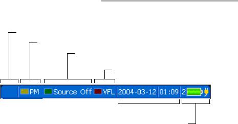
Status Bar
Talk set status (seeking or connected)
Power meter status (detected modulation)
Source/FASTEST/ORL meter status (active wavelength or detected modulation)
VFL status (on/off)
Current date and time 
Battery number/status and DC power status
To access main features:
1.Press the Menu key.
2.Use the arrows to select feature and press Enter.
To activate F1/F2 functions:
1.Use the left/right function arrows (beside F1/F2 keys) to make the desired function or parameter visible.
2.Press the F1 or F2 key located just below.
To access and modify on-screen parameters:
1.Use the arrows to select an on-screen item (drop-down list, keyboard, check box, etc.).
2.Press Enter to activate or open it.
To enter text or numbers with an on-screen keyboard:
Use the left/right function arrows (beside F1/F2 keys) to move the cursor in the text.
Use the up/down and left/right arrows to select a character, then press Enter to add it.
Press OK (F1/F2 key) to accept the element and hide the keyboard.
Multifunction Loss Tester |
15 |

4Customizing Your Multifunction Loss Tester
Selecting the Language of Operation
You may display the user interface in one of six languages (default is English). If other languages become available in the future, you could access them by replacing the unit software (see Upgrading the Embedded Software on page 80). Values are kept in memory when you turn the unit off. You may also revert to factory settings at any time.
To select a new interface language:
1.Press Menu, then select Setup > Unit.
2.Press Next Tab (F1/F2 key) until you get to the Regional tab.
3.Use the arrows to select the Language list, then press Enter to open it.
4.With the current language highlighted, use
the up/down arrows to select the desired language, then press Enter to activate it.
To revert unit to factory-default settings:
1.Press Menu, then select Setup > Unit.
2.Press Factory Settings (F1/F2 key). Values on all tabs of the Unit Setup pane are returned to factory settings.
Multifunction Loss Tester |
17 |

Customizing Your Multifunction Loss Tester
Setting the Date and Time
Setting the Date and Time
The current date and time are displayed on the status bar. When saving results, the unit also saves the corresponding date and time.
You must enter the date according to the year-month-day format and the time according to the 24-hour format.
Note: A dedicated clock battery keeps the date and time accurate. For details, see
Replacing Batteries on page 77.
To set the date and time:
1.Press Menu, then select Setup > Unit.
2.Press Next Tab (F1/F2 key) until you get to the Regional tab.
3.Use the arrows to select any of the date or time settings, then press Enter to display the on-screen keyboard (for details about using
keyboards, see Using Menus and Keypad on page 14).
4.Set the new value and press OK (F1/F2 key).
18 |
FOT-930 |

Customizing Your Multifunction Loss Tester
Adjusting the Brightness and Contrast
Adjusting the Brightness and Contrast
To fit your work environment, you may adjust the LCD brightness and contrast. Values are kept in memory when you turn the unit off. You may also revert to factory settings at any time.
Note: These settings do not apply to the Fiber Inspection Probe display. For details, see Inspecting Fibers with the FIP on page 63.
To adjust the display brightness and contrast:
Press the  key repeatedly to switch between brightness levels (0-4-7-10). OR
1.Press Menu, then select Setup > Unit.
2.Press Next Tab (F1/F2 key) until you get to the LCD tab.
3.Use the up/down arrows to select the
Brightness or Contrast slider.
4.Use the left/right arrows to adjust the brightness or contrast level.
To revert unit to factory-default settings:
1.Press Menu, then select Setup > Unit.
2.Press Factory Settings (F1/F2 key). Values on all tabs of the Unit Setup pane are returned to factory settings.
Multifunction Loss Tester |
19 |

Customizing Your Multifunction Loss Tester
Activating and Setting Screen Saver and Auto-Off
Activating and Setting Screen Saver and
Auto-Off
When you do not use the unit for a while, the display may be dimmed to save power. Your unit may also turn itself off completely.
You can set idle durations for DC and battery operation. Values are kept in memory when you turn the unit off. You may also revert to factory settings at any time.
Note: The ON/OFF button blinks to indicate screen saver activation, but unit operation is not interrupted. Press any key to deactivate the screen saver.
To activate/deactivate the screen saver or auto-off:
1.Press Menu, then select Setup > Unit.
2.Press Next Tab (F1/F2 key) until you get to the Power tab (for auto-off) or Display tab (for screen saver).
3.Use the up/down arrows to select the battery or AC adapter duration list, then press Enter to open the list.
4.With the current duration highlighted, use the up/down arrows to select the desired duration (or Never), then press Enter to confirm.
To revert unit to factory-default settings:
1.Press Menu, then select Setup > Unit.
2.Press Factory Settings (F1/F2 key). Values on all tabs of the Unit Setup pane are returned to factory settings.
20 |
FOT-930 |

5Setting Up Your Multifunction Loss Tester
Installing the EXFO Universal Interface (EUI)
The EUI fixed baseplate is available for connectors with angled (APC) or non-angled (UPC) polishing. A green border around the baseplate indicates that it is for APC-type connectors.
Green border |
|
|
|
|
Bare metal |
||
indicates APC |
|
|
|
|
|
|
(or blue border) |
|
|
|
|
|
|||
option |
|
|
|
|
indicates UPC |
||
|
|
|
|
|
|
|
option |
To install an EUI connector adapter onto the EUI baseplate:
1. Hold the EUI connector adapter so the dust cap opens downwards.
2 |
3 |
4 |
2.Close the dust cap in order to hold the connector adapter more firmly.
3.Insert the connector adapter into the baseplate.
4.While pushing firmly, turn the connector adapter clockwise on the baseplate to lock it in place.
Multifunction Loss Tester |
21 |

Setting Up Your Multifunction Loss Tester
Cleaning and Connecting Optical Fibers
Cleaning and Connecting Optical Fibers
IMPORTANT
To ensure maximum power and to avoid erroneous readings:
Always inspect fiber ends and make sure that they are clean as explained below before inserting them into the port. EXFO is not responsible for damage or errors caused by bad fiber cleaning or handling.
Ensure that your patchcord has appropriate connectors. Joining mismatched connectors will damage the ferrules.
To connect the fiber-optic cable to the port:
1.Inspect the fiber using a fiber inspection microscope. If the fiber is clean, proceed to connecting it to the port. If the fiber is dirty, clean it as explained below.
2.Clean the fiber ends as follows:
2a. Gently wipe the fiber end with a lint-free swab dipped in isopropyl alcohol.
2b. Use compressed air to dry completely.
2c. Visually inspect the fiber end to ensure its cleanliness.
22 |
FOT-930 |
Loading...