


 Loading...
User Guide
MAX-635
Copper and VDSL2/ADSL2+ Multi-play
Test Set

Copyright Information
Copyright Information
Copyright © 2010–2014 EXFO Inc. All rights reserved. No part of this publication may be reproduced, stored in a retrieval system or transmitted in any form, be it electronically, mechanically, or by any other means such as photocopying, recording or otherwise, without the prior written permission of EXFO Inc. (EXFO).
Information provided by EXFO is believed to be accurate and reliable. However, no responsibility is assumed by EXFO for its use nor for any infringements of patents or other rights of third parties that may result from its use. No license is granted by implication or otherwise under any patent rights of EXFO.
EXFO’s Commerce And Government Entities (CAGE) code under the North Atlantic Treaty Organization (NATO) is 0L8C3.
The information contained in this publication is subject to change without notice.
Trademarks
EXFO’s trademarks have been identified as such. However, the presence or absence of such identification does not affect the legal status of any trademark.
Units of Measurement
Units of measurement in this publication conform to SI standards and practices.
Version number 8.0.0
ii |
MAX-635 |

|
Contents |
Contents |
|
Copyright Information ............................................................................................................ |
ii |
Certification Information ...................................................................................................... |
vii |
1 Introducing the MaxTester 635 ................................................................... |
1 |
Key Features and Benefits ....................................................................................................... |
1 |
Typical Applications ................................................................................................................ |
2 |
Using the MaxTester ............................................................................................................... |
3 |
Cable Connections .................................................................................................................. |
6 |
Conventions ............................................................................................................................ |
8 |
2 Safety Information ....................................................................................... |
9 |
Electrical Safety ................................................................................................................... |
10 |
Equipment Ratings ............................................................................................................... |
11 |
3 Getting Started with the MaxTester ......................................................... |
13 |
Turning the Unit On/Off ........................................................................................................ |
13 |
Using Menus and Keypad ..................................................................................................... |
14 |
Keypad .................................................................................................................................. |
15 |
Using Online Help ................................................................................................................. |
16 |
4 Setting Up the MAX-635 ............................................................................. |
17 |
Home .................................................................................................................................... |
17 |
System Settings .................................................................................................................... |
18 |
Display and Language ........................................................................................................... |
19 |
Date and Time ...................................................................................................................... |
20 |
Power ................................................................................................................................... |
21 |
Software Options .................................................................................................................. |
24 |
Information .......................................................................................................................... |
26 |
Upload Setup ........................................................................................................................ |
27 |
Copper and VDSL2/ADSL2+ Multi-play Test Set |
iii |

Contents |
|
|
5 Setting Up Copper Tests ............................................................................. |
35 |
|
|
Copper Test Main Menu ........................................................................................................ |
35 |
|
Test Configuration ................................................................................................................ |
36 |
|
Setup .................................................................................................................................... |
43 |
|
Phone Book .......................................................................................................................... |
44 |
|
Dialer Function ..................................................................................................................... |
52 |
|
Cable Book ........................................................................................................................... |
57 |
|
Application Settings ............................................................................................................. |
63 |
|
Test Lead Compensation ....................................................................................................... |
72 |
|
FED Setup ............................................................................................................................. |
73 |
|
Saving Results ....................................................................................................................... |
79 |
6 Reading Saved Copper Test Results ........................................................... |
83 |
|
|
Read/Upload Result ............................................................................................................... |
83 |
|
Results Summary .................................................................................................................. |
83 |
|
Read Result Menu ................................................................................................................. |
84 |
|
Upload .................................................................................................................................. |
89 |
|
Export ................................................................................................................................... |
90 |
7 |
Multimeter Tests ......................................................................................... |
93 |
|
Multimeter Main Page .......................................................................................................... |
93 |
|
Voltage ................................................................................................................................. |
94 |
|
Current ................................................................................................................................. |
99 |
|
Resistance ........................................................................................................................... |
104 |
|
Resistive Balance ................................................................................................................. |
107 |
|
Isolation .............................................................................................................................. |
110 |
|
Capacitance/Opens ............................................................................................................. |
114 |
|
Station Ground ................................................................................................................... |
118 |
|
Stressed Balance ................................................................................................................. |
121 |
8 |
SmartR™ Features ..................................................................................... |
125 |
|
Pair Detective ...................................................................................................................... |
125 |
|
Pair Detective Result Details ................................................................................................ |
133 |
|
FaultMapper ....................................................................................................................... |
135 |
9 |
Noise Tests ................................................................................................. |
141 |
|
Noise Tests Main Page ......................................................................................................... |
141 |
|
VF Noise ............................................................................................................................. |
142 |
|
Power Influence .................................................................................................................. |
145 |
|
VF Impulse Noise ................................................................................................................ |
148 |
|
WB PSD Noise ..................................................................................................................... |
152 |
|
WB Impulse Noise ............................................................................................................... |
157 |
|
NEXT ................................................................................................................................... |
161 |
iv |
MAX-635 |

|
Contents |
10 Frequency Tests ........................................................................................ |
173 |
Frequency Tests Main Page ................................................................................................. |
173 |
VF/AC Balance ..................................................................................................................... |
174 |
WB Balance ......................................................................................................................... |
180 |
WB Attenuation .................................................................................................................. |
185 |
Load Coils ........................................................................................................................... |
192 |
Locator Tone ....................................................................................................................... |
195 |
TX/RX Tone .......................................................................................................................... |
197 |
11 TDR ............................................................................................................ |
201 |
Continuous ......................................................................................................................... |
201 |
Cable Setup ........................................................................................................................ |
205 |
Load Trace .......................................................................................................................... |
206 |
Result Details ...................................................................................................................... |
207 |
TDR Profile Details .............................................................................................................. |
212 |
12 RFL ............................................................................................................. |
213 |
Single Pair ........................................................................................................................... |
213 |
Separate Good Pair ............................................................................................................. |
215 |
RFL Cable Setup .................................................................................................................. |
218 |
Result Details ...................................................................................................................... |
220 |
13 Copper Auto Tests .................................................................................... |
223 |
Main Menu ......................................................................................................................... |
223 |
POTS Auto Test ................................................................................................................... |
224 |
User Auto Test ..................................................................................................................... |
228 |
Result Details ...................................................................................................................... |
240 |
Profile Details ...................................................................................................................... |
242 |
14 Setting Up DSL/IP Tests ............................................................................ |
247 |
DSL Main Menu Page .......................................................................................................... |
247 |
Test Configuration .............................................................................................................. |
248 |
Test Setup ........................................................................................................................... |
259 |
Setup .................................................................................................................................. |
271 |
Copper and VDSL2/ADSL2+ Multi-play Test Set |
v |

Contents |
|
15 Running DSL/IP Tests and Viewing Results .............................................. |
283 |
DSL/IP Connection Summary ............................................................................................... |
283 |
Ethernet Connection Summary ........................................................................................... |
285 |
WAN Status ........................................................................................................................ |
286 |
LAN Status .......................................................................................................................... |
287 |
VoIP Call ............................................................................................................................. |
288 |
VoIP Summary .................................................................................................................... |
294 |
IPTV Summary .................................................................................................................... |
295 |
Join Leave ........................................................................................................................... |
297 |
DSL Parameter Details ......................................................................................................... |
298 |
DSL Statistics ...................................................................................................................... |
301 |
Band Information ............................................................................................................... |
304 |
Loop Diagnostics ................................................................................................................ |
305 |
Data Tests Summary ........................................................................................................... |
306 |
Web Browser ...................................................................................................................... |
308 |
Bookmarks .......................................................................................................................... |
310 |
16 Saving, Reading, and Exporting DSL/IP Test Results ............................... |
311 |
Saving Results ..................................................................................................................... |
311 |
Read/Export Results ............................................................................................................ |
316 |
17 Maintenance .............................................................................................. |
319 |
General Maintenance .......................................................................................................... |
319 |
Recalibrating the Unit ......................................................................................................... |
320 |
Battery ................................................................................................................................ |
322 |
Recycling and Disposal (Applies to European Union Only) .................................................. |
324 |
18 Troubleshooting ........................................................................................ |
325 |
Solving Common Problems ................................................................................................. |
325 |
LED Statuses ....................................................................................................................... |
327 |
Contacting the Technical Support Group ............................................................................ |
328 |
Transportation .................................................................................................................... |
329 |
19 Warranty .................................................................................................... |
331 |
General Information ........................................................................................................... |
331 |
Liability ............................................................................................................................... |
332 |
Exclusions ........................................................................................................................... |
333 |
Certification ........................................................................................................................ |
333 |
Service and Repairs ............................................................................................................. |
334 |
EXFO Service Centers Worldwide ........................................................................................ |
335 |
........................................................................................................................................... |
335 |
A Technical Specifications ............................................................................ |
337 |
vi |
MAX-635 |

Certification Information
Certification Information
North America Regulatory Statement
This unit was certified by an agency approved in both Canada and the United States of America. It has been evaluated according to applicable North American approved standards for product safety for use in Canada and the United States.
Electronic test and measurement equipment is exempt from FCC part 15, subpart B compliance in the United States of America and from ICES-003 compliance in Canada. However, EXFO Inc. makes reasonable efforts to ensure compliance to the applicable standards.
The limits set by these standards are designed to provide reasonable protection against harmful interference when the equipment is operated in a commercial environment. This equipment generates, uses, and can radiate radio frequency energy and, if not installed and used in accordance with the user guide, may cause harmful interference to radio communications. Operation of this equipment in a residential area is likely to cause harmful interference in which case the user will be required to correct the interference at his own expense.
Modifications not expressly approved by the manufacturer could void the user's authority to operate the equipment.
Copper and VDSL2/ADSL2+ Multi-play Test Set |
vii |

Certification Information
European Community Declaration of Conformity
DECLARATION OF CONFORMITY
Application of Council Directive(s): |
2004/108/EC – The EMC Directive |
|
|
1999/5/EC – The R&TTE Directive |
|
|
93/68/EEC – CE Marking |
|
|
And their amendments |
|
Manufacturer’s Name and Address: |
EXFO Inc. |
EXFO Europe |
|
400 Godin Avenue |
Omega Enterprise Park, Electron Way |
|
Quebec City, Quebec |
Chandlers Ford, Hampshire |
|
G1M 2K2 CANADA |
SO53 4SE ENGLAND |
|
Tel.: +1 418 683-0211 |
Tel.: +44 2380 246810 |
Equipment Type/Environment: |
Test & Measurement / Industrial |
|
Trade Name/Model No.: |
Copper, DSL and Multiplay Test Set / MaxTester 635 |
|
Standard(s) to which Conformity is declared:
EN 61010-1:2001 Edition 2.0
EN 61326-1:2006
Safety requirements for electrical equipment for measurement, control, and laboratory use – Part 1: General requirements
Electrical equipment for measurement, control and laboratory use – EMC requirements – Part 1: General requirements
I, the undersigned, hereby declare that the equipment specified above conforms to the above Directive and Standards.
Manufacturer:
Stephen Bull, E. Eng
Vice-President Research and Development
400 Godin Avenue,
Quebec City, Quebec
G1M 2K2 CANADA
June 4, 2012
viii |
MAX-635 |

1 Introducing the MaxTester 635
The MAX-635 is a handheld device designed for testing ADSL2+ and VDSL2 services between the service provider and the subscriber premises. The unit also qualifies and troubleshoots copper-loop plant by using pass/fail-driven automated functionalities.
The MaxTester 635 test set case is an aluminum enclosure with rubber over mold, which makes it ideal for field use. Its display is a back-lit LCD featuring 480 x 800 resolution. A membrane keypad mounted on the face of the unit features a 14-button keypad used to operate the test set. The following describes the features of the MAX-635.
Key Features and Benefits
Broadcom chipset
IP login
Single-ended copper testing - no remote device required
DSL testing
User-defined automatic testing
Dual Ethernet ports
Customer modem replacement
Color display with graphical analysis
Battery powered
Rugged and weatherproof handheld unit
Copper and VDSL2/ADSL2+ Multi-play Test Set |
1 |

Introducing the MaxTester 635
Typical Applications
Typical Applications
Active and inactive pair Auto Tests
Multimeter tests
Noise tests including power influence and PSD
Frequency tests including balance, load coils, and tracing tone
Fault location tests including TDR and RFL
ADSL2+ and VDSL2 testing
Optional ADSL2+ and VDSL2 bonding support
Supports Ping, FTP, and Traceroute tests with optional support for Web Browser, VoIP testing, and IPTV analysis
Ethernet testing for qualifying FTTx service at the customer premises
Configurable pass/fail results for automated testing
2 |
MAX-635 |
Introducing the MaxTester 635
Using the MaxTester
Using the MaxTester
The MaxTester is tested IEC IP54 which means that it is not affected by dust or water splashing against the enclosure from any direction. This protection is only valid when both side doors are properly closed. If the equipment is used in a manner not specified by the manufacturer, the protection provided by the equipment may be impaired.
The MaxTester is equipped with a series of interfaces shown in the following views:
Left
|
|
|
|
|
|
|
|
|
Head Set Jack (2.5 mm) |
|
|
|
|
|
|
|
|
|
|
||
|
|
|
|
|
|
|
|
|
||
USB Host Port |
|
|
|
|
|
|
|
|||
|
|
|
|
|
|
|
|
|||
|
|
|
|
|
|
|
|
Door |
||
USB Client Port |
||||||||||
|
|
|
|
|
||||||
|
|
|
|
|
|
|
||||
|
|
|
SD |
|
Card (not used) |
|||||
|
|
|
|
|||||||
Right
USB Client Port
DC Power |
Door |
Copper and VDSL2/ADSL2+ Multi-play Test Set |
3 |

Introducing the MaxTester 635
Using the MaxTester
Front
Power LED |
|
Battery LED |
Speaker |
4 |
MAX-635 |

Introducing the MaxTester 635
Using the MaxTester
Back
Screws |
|
|
|
|
|
Screws |
|
|
|
|
|
||
|
|
|
Battery Door |
|||
|
|
|
|
|
|
|
Note: The MAX-635 enclosure may become warm during normal use.
Copper and VDSL2/ADSL2+ Multi-play Test Set |
5 |

Introducing the MaxTester 635
Cable Connections
Cable Connections
The graphics below show the connectors on the MaxTester device.
|
|
|
Ethernet Lan port |
|
|
||||
Ethernet |
|
|
|
|
|
|
|
|
DSL port |
|
|
|
|
|
|
|
|
||
|
|
|
|
|
|
|
|
||
|
|
|
|
|
|
|
|
||
WAN port |
|
|
|
|
|
|
|
|
|
Primary tip/A and |
|
|
|
|
|
|
Secondary tip/A and |
||
|
|
|
|
|
|
||||
|
|
Ground |
|||||||
ring/B connectors |
|
|
ring/B connectors |
||||||
|
|
terminal |
|||||||
|
|
|
|
|
|
||||
Note: When connecting a DSL cable to the DSL port, use the RJ-11 plug end of the cable provided with the unit.
Secondary Tip/A wire of phone line
Secondary Ring/B wire of phone line
Shield of phone line
Primary Tip/A wire of phone line
Primary Ring/B wire of phone line
6 |
MAX-635 |

Introducing the MaxTester 635
Cable Connections
WARNING
A 50 to 500 Vcc limited power source may be present on connector R/T/R1/T1 when the unit is testing isolation resistance. Use with caution.
WARNING
These connections are intended for the express purpose of electrical testing of common telephone line conductors, within the ranges specified in the Technical Specifications on page 281. The device is not intended to be used on telephone lines having voltages greater than 280 VAC or 400 VDC, and it is also not intended to be used on power distribution circuits.
CAUTION
The unit is protected against damage caused by fault voltages that may be present on lines under test. Do not connect the unit if the maximum expected fault voltage is greater than 500 volts.
Copper and VDSL2/ADSL2+ Multi-play Test Set |
7 |

Introducing the MaxTester 635
Conventions
Conventions
Before using the product described in this guide, you should understand the following conventions:
WARNING
Indicates a potentially hazardous situation which, if not avoided, could result in death or serious injury. Do not proceed unless you understand and meet the required conditions.
CAUTION
Indicates a potentially hazardous situation which, if not avoided, may result in minor or moderate injury. Do not proceed unless you understand and meet the required conditions.
CAUTION
Indicates a potentially hazardous situation which, if not avoided, may result in component damage. Do not proceed unless you understand and meet the required conditions.
IMPORTANT
Refers to information about this product you should not overlook.
8 |
MAX-635 |

2 Safety Information
WARNING
The use of controls, adjustments and procedures other than those specified herein may result in exposure to hazardous situations or impair the protection provided by this unit.
IMPORTANT
When you see the following symbol on your unit , make sure that you refer to the instructions provided in your user documentation. Ensure that you understand and meet the required conditions before using your product.
IMPORTANT
Other safety instructions relevant for your product are located throughout this documentation, depending on the action to perform. Make sure to read them carefully when they apply to your situation.
Copper and VDSL2/ADSL2+ Multi-play Test Set |
9 |

Safety Information
Electrical Safety
Electrical Safety
The AC adapter/charger provided with this unit (18 W/9 V) is specifically designed to work with your MaxTester.
WARNING
Use the AC/DC adapter/charger indoors only.
Use only with a Class II AC/DC adapter, power limited output.
On the AC/DC adapter, replacing detachable mains supply cords with inadequately rated cords, may result in overheating of the cord and create a fire risk.
The adapter shall have the appropriate safety mark (e.g. UL, CSA, TUV, CE, etc.) that is acceptable to the authorities in the country where the equipment is to be used.
CAUTION
When using the MaxTester while connected to the AC/DC adapter/charger, make sure you do not position the equipment so that it is difficult to disconnect the adapter/charger from the
AC mains.
WARNING
Use only accessories that meet EXFO specifications.
10 |
MAX-635 |

Safety Information
Equipment Ratings
Equipment Ratings
|
|
Equipment Ratings |
|
|
|
|
|
|
Temperature |
|
|
Operation |
0 °C to 40 °C (32 °F to 104 °F) |
|
Storage |
–40 °C to 70 °C (–40 °F to 158 °F) |
|
|
|
|
Relative humiditya |
|
|
unit |
95 % non-condensing |
|
AC adapter |
0 % to 80 % non-condensing |
|
|
|
|
Maximum operation |
|
3000 m (9842 ft) |
altitude |
|
|
|
|
|
Pollution degree |
|
2 (when plugged to AC mains)b |
|
|
3 (when operated from batteries)c |
Overvoltage category |
|
II |
|
|
|
Input powerd |
|
|
unit |
9-24 V; 18 W; 1.67 A |
|
AC adapter |
|
100 - 240 V; 50/60 Hz; 0.7 A |
|
|
|
a.Measured in 0 °C to 31 °C (32 °F to 87.8 °F) range, decreasing linearly to 50 % at 40 °C (104 °F).
b.For indoor use only.
c.Equipment is normally protected against exposure to direct sunlight, precipitations and full wind pressure.
d.Not exceeding ± 10 % of the nominal voltage.
Copper and VDSL2/ADSL2+ Multi-play Test Set |
11 |
3Getting Started with the MaxTester
Turning the Unit On/Off
When you turn the unit on, you may use it immediately under normal conditions. When the unit is turned off, it keeps the following parameters in its internal memory:
Setup including application settings, phone and cable books, and test lead characteristics.
Profiles consisting of:
Test parameters
User-defined thresholds
Note: Save the current profile before turning the unit off or else any changes are lost. See Save Profile page 37 for more information.
Regional, LCD and energy-saving settings
Test results saved internally vs. USB There are two ways to turn off the MaxTester
Suspend: the next time you turn your unit on, you will quickly return to your work environment.
Shutdown: completely cuts power to the unit; the unit will perform a complete restart routine the next time you use it. You should perform a shutdown if you do not intend to use your unit for a few hours or more.
To turn the unit on:
Press  to start. The unit initializes for a few seconds and displays the Home pane.
Copper and VDSL2/ADSL2+ Multi-play Test Set |
13 |

Getting Started with the MaxTester
Using Menus and Keypad
To enter suspend mode:
Press  for about 2 seconds. The MaxTester will stay in suspend mode for 2 hours, after which it will automatically shutdown. This prevents complete battery discharge and ensures maximum battery performance.
To perform a shutdown:
Hold down  for about 4 seconds. The shutdown process starts.
Note: In both previous cases, if the power adapter is connected, the MaxTester will simulate either a fake suspend or fake shutdown in order to facilitate the charger.
Using Menus and Keypad
You can access various tools from the keypad or menu. Menu options may differ depending on your unit configuration.
Home menu is where you can access Copper Test, DSL/IP Tests, or
System Settings.
Each test has a sub menu.
To navigate through the items, use the arrow keys.
To confirm a choice or enter a menu, press  .
.
To cancel an action or return to the previous item or pane, press  .
.
To return to the home pane, press  .
.
Press  once to return to the Main test menu or twice to return to the Home pane.
Note: Pressing  while a test is running will do nothing. The test can not be running in order to return to the main menu screen.
Note: You can also select an option directly by pressing the function keys corresponding to the on-screen buttons at the bottom of the screen.
14 |
MAX-635 |
Getting Started with the MaxTester
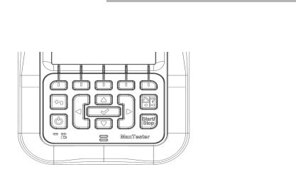
Keypad
Keypad
Arrow keys |
|
|
|
|
|
|
|
|
|
|
|
Function keys |
|||||||
|
|
|
|
||||||||||||||||
|
|
||||||||||||||||||
Back |
|
|
|
|
|
|
|
|
|
|
|
|
|
Home/Help |
|||||
|
|
|
|
|
|
|
|
|
|
|
|
|
|
||||||
|
|
|
|
|
|||||||||||||||
Power |
|
|
|
|
|
|
|
|
|
|
|
|
|
|
|
|
Start/Stop test |
||
|
|
|
|
|
|
|
|
|
|
|
|
|
|
|
|
||||
|
|
|
|
|
|
|
|||||||||||||
Enter |
|
|
|
|
|
|
|
|
|
|
|
|
|
||||||
|
|
|
|
|
|
|
|
|
|
|
|
|
|||||||
Power button on the lower left side of the unit is used to power the unit on and off.
Arrow keys navigate the screen to access and modify parameters.
Function keys activate the corresponding on-screen function button.
Home button brings you to the Home pane of the MAX-635.
Copper and VDSL2/ADSL2+ Multi-play Test Set |
15 |

Getting Started with the MaxTester
Using Online Help
Using Online Help
Online help is available at any time. Most test operations pause while you view help, but will resume automatically when you exit help.
To access help about the current function at any time:
Press and hold the ? key.
16 |
MAX-635 |

4 Setting Up the MAX-635
Home
Home presents the main menu page which allows you to navigate between Copper Test, DSL/IP Tests, and System Settings using the left/right, up/down arrow keys on the keypad.
Press  to bring up the sub-menu of the selected icon:
Copper Test opens the Copper Main menu displaying the copper qualification testing applications.
DSL/IP Tests opens the DSL Main menu for ADSL2+, VDSL2, and multi-play services testing applications.
System Settings allow you to set the parameters of the unit and access to Upload Setup.
Copper and VDSL2/ADSL2+ Multi-play Test Set |
17 |

Setting Up the MAX-635
System Settings
System Settings
System Settings presents a menu of items to setup the unit.
Display and Language provides the setup for backlight, information on the title bar, and language choice.
Date and Time sets the date and time and format.
Power displays the BATTERY Status, Power Schemes, and Calibration.
Software Options allow you to enable/disable purchased feature options.
Information displays information About EXFO
and unit details pertaining to hardware/software/product info.
Upload Setup allows you to enable and select an upload method using the following function keys:
Upload Enable
FTP Setup
Wi-Fi Setup
Ethernet Setup
To navigate between the system settings:
1.Press the up/down left/right arrow keys on the keypad to select an icon.
2.Press  to confirm your selection.
18 |
MAX-635 |

Setting Up the MAX-635
Display and Language
Display and Language
To fit your work environment, you may adjust the LCD brightness, display the time and Active Sync, and change the display language. The values are kept in memory when you turn the unit off.
Note: The LCD Backlight consumes battery power; more brightness, more power consumption.
To adjust the display settings:
1.From  , select System Settings, and then
Display and Language.
2.Use the up/down arrow keys to select the setting to change.
3.Press  to select it.
By using the up/down arrow keys, you can switch between preset brightness levels in the Backlight item. Press  to confirm.
To display the time and Active Sync in the title bar, enable the item. Press  after your selection to confirm.
Use the up/down arrow keys to navigate between the available languages, then press  to select it. You will be prompted to restart your unit.
To set which Home page the unit defaults to when pressing  , highlight Start MaxTester using: and select from the list.
Copper and VDSL2/ADSL2+ Multi-play Test Set |
19 |

Setting Up the MAX-635
Date and Time
Date and Time
When saving results, the unit also saves the corresponding Date and Time.
You can enter the date according to the following formats:
yyyy-mm-dd
dd-mm-yyyy
mm-dd-yyyy
The time can be set according to the 12or 24-hour formats.
You can also modify the time zone and enable an
option so that your unit automatically adjusts the time for the daylight saving period.
To set the date and time:
1.Press  , select System Settings, and then Date and Time.
2.Use the arrows to select any of the date or time settings.
3.Press  to enable the modification controls.
For the date and time, an edit screen is displayed with descriptive function keys. Use the arrow keys to modify the number values, then press  to confirm the change and go back to the previous screen.
Press  to go back to the previous screen without saving the new value.
For the time format, auto daylight saving and time zone values, use the arrow keys to select the desired value, then press  to confirm the change.
20 |
MAX-635 |

Setting Up the MAX-635
Power
Power
Battery Status
The BATTERY Status pane indicates the current power level for the battery.
Note: The battery level might not display after a system upgrade but will become available again after the next full charge.
Power Schemes
You can set your unit to automatically switch to suspend mode independently for the battery or DC power modes. This is useful for example if you want to save battery power but do not want to be hindered by unwanted switches between modes when using DC power.
Power off completely shuts down the unit’s power.
Power suspend puts the unit in sleep mode; you can wake up the system by pressing  .
.
DC IN/BATTERY Idle timeout allows you to set the time duration for the unit to idle (no keys pressed or test being run) before turning off the LCD.
DC IN/BATTERY suspend timeout allows you to set the time duration for the unit to enter sleep mode.
Copper and VDSL2/ADSL2+ Multi-play Test Set |
21 |

Setting Up the MAX-635
Power
Note: Setting the DC IN suspend timeout to the lowest value and not to Never ensures the unit enters suspend mode while the charger is connected. Battery charging time is quickest when the unit is in suspend mode.
Default Power Scheme settings are:
LCD backlight turns off after system idles (no keys pressed) for 10 minutes.
Unit switches to suspend mode after timeout: 10 min
To change the power scheme settings:
1.Press  , select System Settings, and then Power.
2.Select the Power Schemes tab.
3.Under DC IN or BATTERY, use the arrow keys to select Idle/suspend timeout modes. Press  to view the list of available choices or use the left/right arrow keys.
4.Select a new value, then press  to confirm the choice. Repeat for the other modes as needed.
Calibration
The Calibration tab allows you to optimize the battery gas gauge accuracy.
Calibration State:
Completed displays after the calibration procedure has been started and the DC plug was not removed before the end was reached.
In Progress displays when the calibration procedure has been started but has not yet reached the end.
22 |
MAX-635 |
Loading...