


 Loading...
User Guide
FTB-700 Series
OTDR for FTB-1

Copyright © 2006–2013 EXFO Inc. All rights reserved. No part of this publication may be reproduced, stored in a retrieval system or transmitted in any form, be it electronically, mechanically, or by any other means such as photocopying, recording or otherwise, without the prior written permission of EXFO Inc. (EXFO).
Information provided by EXFO is believed to be accurate and reliable. However, no responsibility is assumed by EXFO for its use nor for any infringements of patents or other rights of third parties that may result from its use. No license is granted by implication or otherwise under any patent rights of EXFO.
EXFO’s Commerce And Government Entities (CAGE) code under the North Atlantic Treaty Organization (NATO) is 0L8C3.
The information contained in this publication is subject to change without notice.
Trademarks
EXFO’s trademarks have been identified as such. However, the presence or absence of such identification does not affect the legal status of any trademark.
Units of Measurement
Units of measurement in this publication conform to SI standards and practices.
Patents
Feature(s) of this product is/are protected by one or more of US patent 6,612,750; and Canadian patent 2,800,361 and equivalent patents pending and/or granted in other countries.
Version number: 20.0.0
ii |
FTB-700 Series |

|
Contents |
Contents |
|
Certification Information ..................................................................................................... |
viii |
1 Introducing the FTB-700 OTDR .................................................................... |
1 |
Main Features ......................................................................................................................... |
2 |
Trace Acquisition Modes ......................................................................................................... |
2 |
Optional Software Packages ................................................................................................... |
3 |
Data Post-Processing .............................................................................................................. |
3 |
Bidirectional Analysis Application ........................................................................................... |
4 |
OTDR Basic Principles .............................................................................................................. |
5 |
Conventions ............................................................................................................................ |
7 |
2 Safety Information ....................................................................................... |
9 |
General Safety Information ..................................................................................................... |
9 |
Other Safety Symbols on Your Unit ....................................................................................... |
10 |
Laser Safety Information ....................................................................................................... |
11 |
3 Getting Started with Your OTDR ............................................................... |
13 |
Inserting and Removing Test Modules .................................................................................. |
13 |
Starting Module Applications ............................................................................................... |
18 |
Timer .................................................................................................................................... |
20 |
4 Preparing Your OTDR for a Test ................................................................. |
21 |
Installing the EXFO Universal Interface (EUI) ......................................................................... |
21 |
Cleaning and Connecting Optical Fibers ............................................................................... |
22 |
Naming Trace Files Automatically ......................................................................................... |
24 |
Enabling or Disabling the First Connector Check .................................................................. |
28 |
Setting Macrobend Parameters ............................................................................................. |
29 |
5 Testing Fibers in Auto Mode ...................................................................... |
31 |
6 Testing Fibers in Advanced Mode ............................................................. |
35 |
Setting the Autorange Acquisition Time ............................................................................... |
40 |
Setting the IOR, RBS Coefficient, and Helix Factor ................................................................ |
41 |
Setting Distance Range, Pulse Width, and Acquisition Time ................................................. |
43 |
Enabling the High-Resolution Feature ................................................................................... |
46 |
Enabling or Disabling Analysis After Acquisition ................................................................... |
48 |
Setting Pass/Fail Thresholds .................................................................................................. |
50 |
Setting a Default Span Start and Span End ........................................................................... |
55 |
OTDR |
iii |

Contents |
|
7 Testing Fibers in Template Mode (optional) .............................................. |
57 |
Template Principle ................................................................................................................. |
57 |
Restrictions of Template Mode .............................................................................................. |
58 |
Acquiring the Reference Trace .............................................................................................. |
60 |
Acquiring Traces in Template Mode ...................................................................................... |
62 |
Selecting a Reference Trace ................................................................................................... |
69 |
8 Testing Fibers in Fault Finder Mode ........................................................... |
71 |
Acquiring Traces in Fault Finder Mode .................................................................................. |
71 |
Naming Fault Finder Files Automatically ............................................................................... |
74 |
Selecting the Default File Format for the Fault Finder Traces ................................................. |
76 |
Enabling or Disabling the Confirmation of Fault Finder File Name ........................................ |
78 |
Enabling or Disabling the Storage Feature ............................................................................ |
80 |
Enabling or Disabling the First Connector Check for Fault Finder ......................................... |
81 |
Enabling or Disabling the Touchscreen Keyboard .................................................................. |
83 |
Setting Trace Display Parameters .......................................................................................... |
84 |
Selecting the Distance Units ................................................................................................. |
86 |
9 Customizing Your OTDR .............................................................................. |
89 |
Selecting the Default File Format .......................................................................................... |
89 |
Enabling or Disabling File Name Confirmation ..................................................................... |
91 |
Selecting the Distance Units ................................................................................................. |
93 |
Customizing the Acquisition Distance Range Values ............................................................. |
95 |
Customizing the Acquisition Time Values ............................................................................. |
97 |
Enabling or Disabling the Touchscreen Keyboard .................................................................. |
99 |
Displaying or Hiding the Optional Features ........................................................................ |
100 |
iv |
FTB-700 Series |

|
Contents |
10 Analyzing Traces and Events ................................................................... |
101 |
Graph View ......................................................................................................................... |
102 |
Linear View ......................................................................................................................... |
104 |
Summary Table ................................................................................................................... |
106 |
Events Tab ........................................................................................................................... |
108 |
Measure Tab ....................................................................................................................... |
112 |
Trace Info. Tab .................................................................................................................... |
112 |
Displaying the Graph in Full Screen .................................................................................... |
113 |
Selecting the Default View .................................................................................................. |
115 |
Automatically Displaying the Event Table after Acquisitions ............................................... |
117 |
Automatically Zooming in on the Fiber Span ...................................................................... |
118 |
Using Zoom Controls .......................................................................................................... |
119 |
Setting Trace Display Parameters ........................................................................................ |
122 |
Customizing the Event Table ............................................................................................... |
124 |
Displaying or Hiding a Trace ............................................................................................... |
126 |
Clearing Traces from the Display ......................................................................................... |
128 |
Viewing and Modifying Current Trace Settings ................................................................... |
129 |
Modifying Events ................................................................................................................ |
134 |
Inserting Events .................................................................................................................. |
138 |
Deleting Events ................................................................................................................... |
140 |
Managing Comments ......................................................................................................... |
142 |
Changing the Attenuation of Fiber Sections ....................................................................... |
144 |
Setting the Analysis Detection Thresholds .......................................................................... |
146 |
Analyzing or Reanalyzing a Trace ........................................................................................ |
149 |
Analyzing the Fiber on a Specific Fiber Span ....................................................................... |
151 |
Enabling or Disabling the Detection of Reflective Ends of Fiber .......................................... |
152 |
Swapping Traces ................................................................................................................. |
155 |
Opening Trace Files ............................................................................................................. |
156 |
11 Analyzing the Results Manually .............................................................. |
161 |
Selecting the Attenuation and Loss Values that Will Be Displayed ...................................... |
161 |
Using Markers ..................................................................................................................... |
163 |
Getting Event Distances and Relative Powers ...................................................................... |
164 |
Getting Event Loss (Four-Point and Least-Square Approximation) ...................................... |
165 |
Getting Attenuation (Two-Point and Least-Square Approximation) .................................... |
170 |
Getting Reflectance ............................................................................................................ |
172 |
Getting Optical Return Loss (ORL) ....................................................................................... |
173 |
12 Managing Trace Files from the OTDR Test Application .......................... |
175 |
Saving a Trace in a Different Format ................................................................................... |
175 |
OTDR Trace File Compatibility ............................................................................................. |
176 |
Copying, Moving, Renaming, or Deleting Trace Files .......................................................... |
178 |
OTDR |
v |

Contents |
|
13 Creating and Generating Reports ............................................................ |
179 |
Adding Information to the Test Results ............................................................................... |
179 |
Generating a Report ........................................................................................................... |
181 |
14 Using the OTDR as a Light Source ............................................................ |
187 |
15 Analyzing Traces with the Bidirectional Analysis Application |
|
(Optional) .................................................................................................. |
191 |
Starting and Exiting the Bidirectional Analysis Application ................................................. |
193 |
Creating Bidirectional Measurement Files ........................................................................... |
195 |
Opening Existing Bidirectional Measurement Files .............................................................. |
199 |
Displaying Traces and Bidirectional Measurement .............................................................. |
200 |
Viewing Results .................................................................................................................. |
202 |
Reanalyzing Traces and Regenerating the Bidirectional Measurement ................................ |
213 |
Modifying the Alignment of Unidirectional Traces .............................................................. |
215 |
Using Zoom Controls .......................................................................................................... |
219 |
Using Markers to Edit Events .............................................................................................. |
223 |
Inserting Events .................................................................................................................. |
225 |
Modifying Events ................................................................................................................ |
229 |
Deleting Events ................................................................................................................... |
233 |
Changing the Attenuation of Fiber Sections ....................................................................... |
235 |
Setting General Parameters ................................................................................................ |
238 |
Customizing the Events Table ............................................................................................. |
241 |
Saving the Span-Start and Span-End Information ............................................................... |
244 |
Setting Pass/Fail Thresholds ................................................................................................ |
245 |
Modifying Trace Analysis Settings ....................................................................................... |
250 |
Saving Traces ...................................................................................................................... |
255 |
Exporting Unidirectional Traces from Bidirectional Files ...................................................... |
257 |
Adding Information to the Test Results ............................................................................... |
259 |
Creating Reports ................................................................................................................. |
261 |
16 Maintenance .............................................................................................. |
265 |
Cleaning EUI Connectors .................................................................................................... |
265 |
Verifying Your OTDR ........................................................................................................... |
268 |
Recalibrating the Unit ......................................................................................................... |
276 |
Recycling and Disposal (Applies to European Union Only) .................................................. |
277 |
17 Troubleshooting ........................................................................................ |
279 |
Contacting the Technical Support Group ............................................................................ |
282 |
Transportation .................................................................................................................... |
283 |
vi |
FTB-700 Series |

|
Contents |
18 Warranty ................................................................................................... |
285 |
General Information ........................................................................................................... |
285 |
Liability ............................................................................................................................... |
286 |
Exclusions ........................................................................................................................... |
286 |
Certification ........................................................................................................................ |
286 |
Service and Repairs ............................................................................................................. |
287 |
EXFO Service Centers Worldwide ........................................................................................ |
288 |
A Technical Specifications ........................................................................... |
289 |
B Description of Event Types ...................................................................... |
293 |
Span Start .......................................................................................................................... |
294 |
Span End ........................................................................................................................... |
294 |
Short Fibers ....................................................................................................................... |
294 |
Continuous Fiber ............................................................................................................... |
295 |
End of Analysis .................................................................................................................. |
296 |
Non-Reflective Event .......................................................................................................... |
297 |
Reflective Event ................................................................................................................. |
298 |
Positive Event ..................................................................................................................... |
299 |
Launch Level ...................................................................................................................... |
300 |
Fiber Section ...................................................................................................................... |
301 |
Merged Event .................................................................................................................... |
302 |
Echo .................................................................................................................................. |
308 |
Reflective Event (Possible Echo) ......................................................................................... |
309 |
Index .............................................................................................................. |
311 |
OTDR |
vii |

Certification Information
Certification Information
North America Regulatory Statement
This unit was certified by an agency approved in both Canada and the United States of America. It has been evaluated according to applicable North American approved standards for product safety for use in Canada and the United States.
Electronic test and measurement equipment is exempt from FCC part 15, subpart B compliance in the United States of America and from ICES-003 compliance in Canada. However, EXFO Inc. makes reasonable efforts to ensure compliance to the applicable standards.
The limits set by these standards are designed to provide reasonable protection against harmful interference when the equipment is operated in a commercial environment. This equipment generates, uses, and can radiate radio frequency energy and, if not installed and used in accordance with the user guide, may cause harmful interference to radio communications. Operation of this equipment in a residential area is likely to cause harmful interference in which case the user will be required to correct the interference at his own expense.
Modifications not expressly approved by the manufacturer could void the user's authority to operate the equipment.
European Community Declaration of Conformity
An electronic version of the declaration of conformity for your product is available on our website at www.exfo.com. Refer to the product’s page on the Web site for details.
viii |
FTB-700 Series |

1 Introducing the FTB-700 OTDR
The FTB-700 OTDR allows you to characterize a fiber-optic span, usually optical fiber sections joined by splices and connectors. The optical time domain reflectometer (OTDR) provides an inside view of the fiber, and can calculate fiber length, attenuation, breaks, total return loss, and splice, connector and total losses.
FTB-730 / FTB-730G / FTB-730G+
|
Active LED |
|
|
|
OTDR port (singlemode |
|
|
|
|
||
|
|
|
|
||
|
|
|
|||
|
|
|
|
live and On-line power |
|
|
|
|
|
meter) |
|
|
|
|
|
OTDR port (singlemode) |
|
|
|
|
|||
FTB-720 / FTB-720G / FTB-720G+
|
|
|
|
|
|
|
|
|
OTDR port (multimode) |
|
|
|
|
|
|
|
|
|
|
|
|
|
|
|
|
|
|
|
|
|
|
|
|
|
|
|
|
|
|
|
|
|
|
|
|
|
|
||
|
|
|
Active LED |
|
|
|
|
||
|
|
|
|
|
|
|
|
||
|
|
|
|
|
|
|
OTDR port (singlemode) |
||
|
|
|
|
|
|
|
|||
|
|
|
|
|
|
||||
|
|
|
|
|
|
|
|
|
|
|
|
|
|
|
|
|
|
|
|
|
|
|
|
|
|
|
|
|
|
|
|
|
|
|
|
|
|
|
|
OTDR port (singlemode live)
OTDR |
1 |

Introducing the FTB-700 OTDR
Main Features
Main Features
The OTDR:
Offers impressive dynamic range with short dead zones
Performs quick acquisitions with low noise levels to enable accurate low-loss splice location.
Acquires OTDR traces made of up to 256 000 points that provide a sampling resolution as fine as 4 cm.
Includes a light source.
Trace Acquisition Modes
The OTDR application provides the following trace acquisition modes:
Auto: Automatically calculates fiber length, sets acquisition parameters, acquires traces, and displays event tables and acquired traces.
Advanced: Offers all the tools needed to perform integral OTDR tests and measurements and gives you control over all test parameters.
Template (optional): Tests fibers and compares the results to a reference trace that was previously acquired and analyzed. This allows you to save time when testing a large number of fibers. Reference trace documentation is also automatically copied to new acquisitions.
Fault Finder: Rapidly locates fiber ends and displays the length of the fiber under test. This allows you to perform quick tests without having to set all the acquisition parameters.
2 |
FTB-700 Series |
Introducing the FTB-700 OTDR
Optional Software Packages
Optional Software Packages
There are two optional software packages offered with the application. With the optional Auto Diagnostic (AD) software package you can:
Have access to the “linear view”, which displays the events sequentially, from left to right.
Find macrobends and view the related information.
View the summary table, which gives, for each wavelength, the global status of the results, the span loss and span ORL values.
Test in Fault Finder mode, to rapidly locate fiber ends.
With the optional Event Characterization (EC) software package you can:
Have access to the OTDR Bidirectional application and perform a bidirectional analysis on two unidirectional OTDR traces.
Test in Template Mode, test fibers and compare the results to a reference trace.
Data Post-Processing
You can install the FastReporter application (available on the DVD that came with your product) on a computer to view and analyze traces without having to use the FTB-1 and an OTDR. You can also access more features such as:
customized printout
batch printing
conversion of traces to many formats such as Telcordia or ASCII
OTDR |
3 |

Introducing the FTB-700 OTDR
Bidirectional Analysis Application
Bidirectional Analysis Application
Note: This function is available with the optional Event Characterization (EC) software package only.
You can improve the accuracy of your loss measurements with the bidirectional analysis application (available with OTSView). This utility uses OTDR acquisitions from both ends of a fiber span (singlemode traces only) to average loss results for each event.
4 |
FTB-700 Series |

Introducing the FTB-700 OTDR
OTDR Basic Principles
OTDR Basic Principles
An OTDR sends short pulses of light into a fiber. Light scattering occurs in the fiber due to discontinuities such as connectors, splices, bends, and faults. An OTDR then detects and analyzes the backscattered signals. The signal strength is measured for specific intervals of time and is used to characterize events.
The OTDR calculates distances as follows:
c t
Distance = -- -- n 2
where
c = speed of light in a vacuum (2.998 x 10⁸ m/s)
t = time delay from the launch of the pulse to the reception of the pulse
n = index of refraction of the fiber under test (as specified by the manufacturer)
OTDR |
5 |

Introducing the FTB-700 OTDR
OTDR Basic Principles
An OTDR uses the effects of Rayleigh scattering and Fresnel reflection to measure the fiber’s condition, but the Fresnel reflection is tens of thousands of times greater in power level than the backscatter.
Rayleigh scattering occurs when a pulse travels down the fiber and small variations in the material, such as variations and discontinuities in the index of refraction, cause light to be scattered in all directions. However, the phenomenon of small amounts of light being reflected directly back toward the transmitter is called backscattering.
Fresnel reflections occur when the light traveling down the fiber encounters abrupt changes in material density that may occur at connections or breaks where an air gap exists. A very large quantity of light is reflected, as compared with the Rayleigh scattering. The strength of the reflection depends on the degree of change in the index of refraction.
|
|
|
Light pulses |
|
|
Light pulses |
|||||||||||||||
|
|
|
|
|
|
|
|
|
|
|
|
|
|
|
|
|
|||||
|
Laser |
|
|
|
|
Optical |
|
|
|
|
|
|
|
OTDR |
|
|
|
Fiber |
|
||
|
|
|
|
|
|
|
|
|
|
|
|
|
|||||||||
|
diode |
|
|
|
|
|
|
||||||||||||||
|
|
|
|
|
coupler |
|
|
|
port |
|
|
|
|
|
|||||||
|
|
|
|
|
|
|
|
|
|
||||||||||||
|
|
|
|
|
|
|
|
Returned signal |
Reflections come back |
||||||||||||
|
|
|
|
|
|
|
|
||||||||||||||
|
|
|
|
|
|
|
|
||||||||||||||
|
|
|
|
|
|
|
|
|
|
|
|
|
|
|
|
|
to the OTDR |
||||
|
|
|
|
|
|
|
|
|
|
|
|
|
|
|
|
|
|
|
|
|
|
|
|
|
|
|
|
|
Avalanche |
|
|
|
|
|
|
|
|||||||
|
|
|
|
|
|
photodetector (APD) |
|
|
|
|
|
|
|
||||||||
|
|
|
|
|
|
|
|
|
|
|
|
|
|
|
|
|
|
|
|
|
|
|
|
|
|
|
|
|
|
|
|
|
|
|
|
|
|
|
|
|
|
|
|
|
Pulse |
|
|
|
|
|
|
|
|
|
|
|
|
|
|
|
|
|
|
|
|
|
|
|
|
|
|
|
|
|
|
|
|
|
|
|
|
|
|
|
|
||
|
generator |
|
|
|
|
|
|
|
|
|
|
|
|
|
|
|
|
|
|
|
|
|
|
|
|
|
|
|
|
|
|
|
|
|
|
|
|
|
|
|
|
|
|
|
|
|
|
|
|
Analog-to-digital |
|
|
|
|
|
|
|
||||||||
|
Set of |
|
|
|
|
|
converter (A/D) |
|
|
|
|
|
|
|
|||||||
|
|
|
|
|
|
|
|
|
|||||||||||||
|
|
|
|
|
|
|
|
|
|
|
|
|
|
|
|
|
|
|
|
|
|
instructions |
|
|
|
|
|
|
|
Analyzed signal |
|
|
|
|
|
||||||||
|
|
|
|
|
|
|
|
|
|
|
|
||||||||||
|
|
|
|
|
|
|
|
|
|
|
|
|
|
||||||||
|
|
|
|
|
|
|
|
|
|
|
|
|
|
|
|
|
|
|
|
|
|
|
|
|
Microprocessor |
|
|
|
|
|
|
Display |
|
|
|
|
|||||||
|
|
|
|
|
|
|
|
|
|
|
|
|
|||||||||
|
|
|
|
|
|
|
|
|
|
|
|
|
|
|
|
|
|
|
|
|
|
When the full trace is displayed, each point represents an average of many sampling points. You will have to zoom to see each point.
6 |
FTB-700 Series |

Introducing the FTB-700 OTDR
Conventions
Conventions
Before using the product described in this guide, you should understand the following conventions:
WARNING
Indicates a potentially hazardous situation which, if not avoided, could result in death or serious injury. Do not proceed unless you understand and meet the required conditions.
CAUTION
Indicates a potentially hazardous situation which, if not avoided, may result in minor or moderate injury. Do not proceed unless you understand and meet the required conditions.
CAUTION
Indicates a potentially hazardous situation which, if not avoided, may result in component damage. Do not proceed unless you understand and meet the required conditions.
IMPORTANT
Refers to information about this product you should not overlook.
OTDR |
7 |

2 Safety Information
General Safety Information
WARNING
Do not install or terminate fibers while a light source is active. Never look directly into a live fiber and ensure that your eyes are protected at all times.
WARNING
The use of controls, adjustments and procedures other than those specified herein may result in exposure to hazardous situations or impair the protection provided by this unit.
IMPORTANT
When you see the following symbol on your unit |
, make sure |
that you refer to the instructions provided in your user |
|
documentation. Ensure that you understand and meet the required conditions before using your product.
IMPORTANT
Other safety instructions relevant for your product are located throughout this documentation, depending on the action to perform. Make sure to read them carefully when they apply to your situation.
OTDR |
9 |

Safety Information
Other Safety Symbols on Your Unit
Other Safety Symbols on Your Unit
One or more of the following symbols may also appear on your unit.
Symbol |
Meaning |
|
|
|
|
|
Direct current |
|
|
|
Alternating current |
|
|
|
Both direct and alternating current |
|
|
|
The unit is equipped with an earth (ground) terminal. |
|
|
|
The unit is equipped with a protective conductor terminal. |
|
|
|
The unit is equipped with a frame or chassis terminal. |
|
|
|
On (Power) |
|
|
|
Off (Power) |
|
|
10 |
FTB-700 Series |

Safety Information
Laser Safety Information
Laser Safety Information
Your instrument is a Class 1M laser product in compliance with standards IEC 60825-1: 2007 and 21 CFR 1040.10, except for deviations pursuant to Laser Notice No. 50, dated June 24, 2007. Invisible laser radiation may be encountered at the output port.
WARNING
Viewing the laser output with certain optical instrument (for example, eye loupes, magnifiers, and microscopes) within a distance of 100 mm may pose an eye hazard.
The following label(s) indicate that the product contains a Class 1M source:
Affixed to module’s side panel
For more information on product safety and equipment ratings, refer to the user documentation of your platform.
OTDR |
11 |
3Getting Started with Your OTDR
Inserting and Removing Test Modules
CAUTION
Never insert or remove a module while the FTB-1 is turned on. This will result in immediate and irreparable damage to both the module and unit.
CAUTION
To avoid damaging your unit, use it only with modules approved by EXFO.
To insert a module into the FTB-1:
1.Turn off your unit (Shutdown).
2.Position the unit so that its front panel rests on a flat surface such as a table.
OTDR |
13 |

Getting Started with Your OTDR
Inserting and Removing Test Modules
Place the module on the platform making sure that the bumpers and the shorter sides of the module are flush with those of the platform. If necessary, slightly move the module until alignment is correct.
|
|
|
|
|
|
|
|
14 |
|
|
FTB-700 Series |

Getting Started with Your OTDR
Inserting and Removing Test Modules
3.Using a flat screwdriver, turn the screws (4) clockwise until they are tightened.
This will secure the module into its “seated” position.
Turn screws clockwise
Back panel
When you turn on the unit, the startup sequence will automatically detect the module.
OTDR |
15 |

Getting Started with Your OTDR
Inserting and Removing Test Modules
To remove a module from the FTB-1:
1.Turn off your unit (Shutdown).
2.Position the unit so that its front panel rests on a flat surface such as a table.
3.Using a flat screwdriver, turn the screws (4) counterclockwise until they are loose. Since they are captive screws, you cannot remove them completely.
Turn screws counterclockwise
Back panel
16 |
FTB-700 Series |

Getting Started with Your OTDR
Inserting and Removing Test Modules
4. Hold the module by its sides (NOT by the connectors) and pull it up.
CAUTION
Pulling a module by its connectors could seriously damage both the module and connector. Always pull a module by its casing.
OTDR |
17 |
Starting Module Applications
Starting Module Applications
Your modules can be configured and controlled from their dedicated applications in Mini ToolBox.
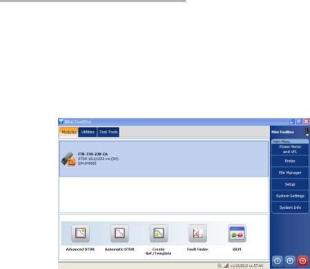
To start a module application:
From Mini ToolBox, at the bottom of the window, press the button corresponding to the desired application.
18 |
FTB-700 Series |

Starting Module Applications
For the FTB-700G Series, from Mini ToolBox, select the OTDR module, then press the button corresponding to the desired application. Only one application can run at a time, either NetBlazer or one OTDR application.
Note: To start the NetBlazer application, refer either to the Transport Application user guide or to the Ethernet/Packet Sync/FC/Wireless user guide for more information.
OTDR |
19 |

Timer
To start the Power Meter or Probe application:
From Main Menu, press Power Meter or Probe.
The main window (shown below) contains all the commands required to control the OTDR:
Data display
Button bar
Function
Tabs
Note: Due to screen resolution, the appearance of your OTDR application may vary slightly from the illustrations presented in this user guide.
Timer
Once the acquisition has begun, a timer is displayed on the right-hand side of the screen, indicating the remaining time until the next acquisition.
20 |
FTB-700 Series |

4 Preparing Your OTDR for a Test
Installing the EXFO Universal Interface (EUI)
The EUI fixed baseplate is available for connectors with angled (APC) or non-angled (UPC) polishing. A green border around the baseplate indicates that it is for APC-type connectors.
Green border |
|
|
|
|
Bare metal |
||
indicates APC |
|
|
|
|
|
|
(or blue border) |
|
|
|
|
|
|||
option |
|
|
|
|
indicates UPC |
||
|
|
|
|
|
|
|
option |
To install an EUI connector adapter onto the EUI baseplate:
1. Hold the EUI connector adapter so the dust cap opens downwards.
2 |
3 |
4 |
2.Close the dust cap in order to hold the connector adapter more firmly.
3.Insert the connector adapter into the baseplate.
4.While pushing firmly, turn the connector adapter clockwise on the baseplate to lock it in place.
OTDR |
21 |

Preparing Your OTDR for a Test
Cleaning and Connecting Optical Fibers
Cleaning and Connecting Optical Fibers
IMPORTANT
To ensure maximum power and to avoid erroneous readings:
Always inspect fiber ends and make sure that they are clean as explained below before inserting them into the port. EXFO is not responsible for damage or errors caused by bad fiber cleaning or handling.
Ensure that your patchcord has appropriate connectors. Joining mismatched connectors will damage the ferrules.
To connect the fiber-optic cable to the port:
1.Inspect the fiber using a fiber inspection microscope. If the fiber is clean, proceed to connecting it to the port. If the fiber is dirty, clean it as explained below.
2.Clean the fiber ends as follows:
2a. Gently wipe the fiber end with a lint-free swab dipped in isopropyl alcohol.
2b. Use compressed air to dry completely.
2c. Visually inspect the fiber end to ensure its cleanliness.
22 |
FTB-700 Series |
Loading...