


User Guide
BV10
Performance Endpoint Unit

Copyright © 2010–2014 EXFO Inc. All rights reserved. No part of this publication may be reproduced, stored in a retrieval system or transmitted in any form, be it electronically, mechanically, or by any other means such as photocopying, recording or otherwise, without the prior written permission of EXFO Inc. (EXFO).
Information provided by EXFO is believed to be accurate and reliable. However, no responsibility is assumed by EXFO for its use nor for any infringements of patents or other rights of third parties that may result from its use. No license is granted by implication or otherwise under any patent rights of EXFO.
EXFO’s Commerce And Government Entities (CAGE) code under the North Atlantic Treaty Organization (NATO) is 0L8C3.
The information contained in this publication is subject to change without notice.
Trademarks
EXFO’s trademarks have been identified as such. However, the presence or absence of such identification does not affect the legal status of any trademark.
Units of Measurement
Units of measurement in this publication conform to SI standards and practices.
December 4, 2014
Version number: 3.0.0.1
ii |
BV10 |

Certification Information
Certification Information
North America Regulatory Statement
This unit was certified by an agency approved in both Canada and the United States of America. It has been evaluated according to applicable North American approved standards for product safety for use in Canada and the United States.
Electronic test and measurement equipment is exempt from FCC part 15, subpart B compliance in the United States of America and from ICES-003 compliance in Canada. However, EXFO Inc. makes reasonable efforts to ensure compliance to the applicable standards.
The limits set by these standards are designed to provide reasonable protection against harmful interference when the equipment is operated in a commercial environment. This equipment generates, uses, and can radiate radio frequency energy and, if not installed and used in accordance with the user guide, may cause harmful interference to radio communications. Operation of this equipment in a residential area is likely to cause harmful interference in which case the user will be required to correct the interference at his own expense.
Modifications not expressly approved by the manufacturer could void the user's authority to operate the equipment.
European Community Declaration of Conformity
An electronic version of the declaration of conformity for your product is available on our website at www.exfo.com. Refer to the product’s page on the Web site for details.
Laser
This product complies with 21 CFR 1040.10 except for deviations pursuant to Laser Notice No. 50, dated June 24, 2007 and with IEC/EN 60825-1.
BV10-100 and BV10-1000 |
iii |

|
Contents |
|
|
Certification Information ....................................................................................................... |
iii |
1 |
Introducing the BV10 .................................................................................... |
1 |
|
Features ................................................................................................................................. |
1 |
|
BrixWorx for Turn Up .............................................................................................................. |
2 |
|
Conventions ............................................................................................................................ |
3 |
2 |
Safety Information ...................................................................................... |
5 |
|
Additional Laser Safety Information ....................................................................................... |
6 |
|
Installation Instruction Warnings ............................................................................................ |
7 |
|
Other Safety Symbols on Your Unit ......................................................................................... |
8 |
3 |
Getting Started ............................................................................................. |
9 |
|
Installing the BV10 in a Rack .................................................................................................. |
9 |
|
Connecting the Power .......................................................................................................... |
10 |
4 Physical Interfaces, LEDs, and Buttons ...................................................... |
15 |
|
|
BV10 Models ....................................................................................................................... |
15 |
|
Port Availability on BV10 ..................................................................................................... |
16 |
|
Connecting the TEST Port Interface ....................................................................................... |
16 |
|
Connecting the Management Interfaces ............................................................................... |
18 |
|
LEDs ..................................................................................................................................... |
20 |
|
RESET and DEFAULT Buttons ................................................................................................. |
21 |
5 Managing BV10 Verifier on BrixWorx ........................................................ |
23 |
|
|
Configuring BV10 Verifier for BrixWorx Registry ................................................................... |
23 |
|
Configuring a Test ................................................................................................................. |
24 |
|
Verifier Health Information ................................................................................................... |
28 |
6 Introducing the BV10 CLI ............................................................................ |
29 |
|
|
Command Line Interface ....................................................................................................... |
29 |
|
Connecting to the BV10 to a Console ................................................................................... |
30 |
|
Entering Commands ............................................................................................................. |
33 |
|
CLI Session ............................................................................................................................ |
37 |
7 |
CLI Command Reference ............................................................................ |
39 |
|
Conventions .......................................................................................................................... |
39 |
|
Command Availability ........................................................................................................... |
39 |
|
Alphabetical List of CLI Commands ....................................................................................... |
40 |
|
Operation Commands .......................................................................................................... |
42 |
|
Configuration Commands .................................................................................................... |
58 |
iv |
BV10 |

8 |
Test Applications ........................................................................................ |
73 |
|
Smart Loopback Test ............................................................................................................. |
74 |
|
Ping Test ............................................................................................................................... |
76 |
|
TWAMP Light Responder Test ............................................................................................... |
77 |
|
UDP Echo Responder Test ..................................................................................................... |
78 |
|
Ethernet OAM Handling Test ................................................................................................. |
79 |
9 |
Power Failure Recovery .............................................................................. |
81 |
10 Maintenance ............................................................................................... |
83 |
|
|
Cleaning LC Connectors ........................................................................................................ |
84 |
|
Recycling and Disposal (Applies to European Union Only) .................................................... |
84 |
11 Troubleshooting ......................................................................................... |
85 |
|
|
Solving Common Problems ................................................................................................... |
85 |
|
Contacting the Technical Support Group .............................................................................. |
86 |
|
Transportation ...................................................................................................................... |
86 |
12 Warranty ..................................................................................................... |
87 |
|
|
General Information ............................................................................................................. |
87 |
|
Liability ................................................................................................................................. |
88 |
|
Exclusions ............................................................................................................................. |
89 |
|
Certification .......................................................................................................................... |
89 |
|
Service and Repairs ............................................................................................................... |
90 |
|
EXFO Service Centers Worldwide .......................................................................................... |
91 |
A |
Specifications ............................................................................................. |
93 |
|
General Specifications ......................................................................................................... |
93 |
|
Electrical Interface ............................................................................................................... |
95 |
|
Optical Interface .................................................................................................................. |
95 |
B |
Glossary ...................................................................................................... |
97 |
|
Acronym List ........................................................................................................................ |
97 |
|
Ethernet Cables ................................................................................................................. |
102 |
Index .............................................................................................................. |
105 |
|
BV10-100 and BV10-1000 |
v |

1 Introducing the BV10
Highly cost-effective Ethernet performance monitoring device providing complete network visibility for mobile backhaul, Carrier Ethernet, and PTN networks.
Features
Fully integrated in EXFO’s end-to-end mobile backhaul solution for service turn-up, troubleshooting, and performance monitoring.
Offers complete network visibility at a third of the cost of traditional Ethernet NID solutions.
Simple and remote management for zero-truck-roll network maintenance.
Completely standards-based, supporting Ethernet OAM, with 802.1ag and Y.1731 message response as a performance endpoint, as well as TWAMP (RFC 5357).
Capability to perform full-line-rate loopback from layer 2 up to layer 4 with rates of 10/100/1000 Mbit/s.
BV10-100 and BV10-1000 |
1 |

Introducing the BV10
BrixWorx for Turn Up
BrixWorx for Turn Up
BrixWorx for Turn Up is a system designed for Turn-Up and reflector testing with no monitoring capability. BrixWorx for Turn Up supports a central management system, Verifier management for the supported Verifier models, and user management. BrixWorx for Turn Up does not support active or passive testing.
The BV10 Verifier is designed specifically for Ethernet OAM Handling, UDP Echo Responder, TWAMP Light Responder, and Smart Loopback test features. These features are enabled by loading the tests on the Verifier Information page (Additional Services section) and in some cases specifying parameters, such as a UDP Listening port for TWAMP or the mode for Smart Loopback.
For more information, refer to the BrixWorx for Turn Up Getting Started guide to learn more about the features of the BrixWorx for Turn Up system and the BrixWorx User Guide to learn more about the Verifier Information page.
2 |
BV10 |

Introducing the BV10
Conventions
Conventions
Before using the product described in this guide, you should understand the following conventions:
WARNING
Indicates a potentially hazardous situation which, if not avoided, could result in death or serious injury. Do not proceed unless you understand and meet the required conditions.
CAUTION
Indicates a potentially hazardous situation which, if not avoided, may result in minor or moderate injury. Do not proceed unless you understand and meet the required conditions.
CAUTION
Indicates a potentially hazardous situation which, if not avoided, may result in component damage. Do not proceed unless you understand and meet the required conditions.
IMPORTANT
Refers to information about this product you should not overlook.
BV10-100 and BV10-1000 |
3 |
2 Safety Information
WARNING
Do not install or terminate fibers while a light source is active. Never look directly into a live fiber and ensure that your eyes are protected at all times.
WARNING
The use of controls, adjustments and procedures, namely for operation and maintenance, other than those specified herein may result in hazardous radiation exposure or impair the protection provided by this unit.
IMPORTANT
When you see the following symbol on your unit |
, make sure |
that you refer to the instructions provided in your user |
|
documentation. Ensure that you understand and meet the required conditions before using your product.
IMPORTANT
Other safety instructions relevant for your product are located throughout this documentation, depending on the action to perform. Make sure to read them carefully when they apply to your situation.
BV10-100 and BV10-1000 |
5 |

Safety Information
Additional Laser Safety Information
Additional Laser Safety Information
WARNING
This product employs Class 1 Laser SFP. Invisible laser radiation may be encountered at the output port. The laser classification is reproduced on the pluggable transceiver or in its documentation.
WARNING
When the LASER LED is on or flashing, the BV10 is transmitting an optical signal on the SFP transceiver port.
6 |
BV10 |

Safety Information
Installation Instruction Warnings
Installation Instruction Warnings
CAUTION
No user serviceable parts are contained inside. Contact the manufacturer regarding service of this equipment.
IMPORTANT
All wiring and installation must be in accordance with local building and electrical codes acceptable to the authorities in the countries where the equipment is installed and used.
CAUTION
Electrostatic Discharge (ESD) Sensitive Equipment:
Units can be damaged by static electrical discharge. To minimize the risk of damage, dissipate static electricity by touching a grounded unpainted metal object
before removing, inserting, or handling the unit.
before connecting or disconnecting cables to/from the unit.
before inserting or removing SFP transceiver to/from the unit.
CAUTION
For DC version, the BV10 must be installed in Restricted Access Locations.
IMPORTANT
Unauthorized modifications to this equipment shall void the user’s authority to operate this equipment.
BV10-100 and BV10-1000 |
7 |
Safety Information
Other Safety Symbols on Your Unit
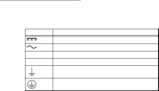
Other Safety Symbols on Your Unit
One or more of the following symbols may also appear on your unit.
Symbol |
Meaning |
|
|
Direct current.
Alternating current.
+Plus; positive polarity.
–Minus, negative polarity.
The unit is equipped with an earth (ground) terminal.
The unit is equipped with a protective conductor terminal.
8 |
BV10 |

3 Getting Started
Installing the BV10 in a Rack
The BV10 can be mounted in a rack using the rack mount accessory kit (ordered separately). The accessory kit shelf holds up to four BV10.
To install the BV10 in a rack:
1.Attach the brackets of the supplied shelf unit to your rack using the supplied screws.
2.If cables have been attached to the BV10, disconnect all of them as well as the ground lug from the unit.
3.Slide the unit into the desired slot from front to back.
4.With the unit completely inserted into the slot, tighten the thumb screw at the back of the unit.
5.Connect all cables and the ground lug, as explained in the next sections.
BV10-100 and BV10-1000 |
9 |

Getting Started
Connecting the Power
Connecting the Power
The BV10 is available with either an AC power supply, DC +24 V connector, or DC –48 V connector.
As soon as the BV10 is connected to a live power supply, the POWER LED turns on. If the POWER LED does not turn on, there is a power failure at the source or the unit is damaged. The STATUS LED indicates whether or not the unit is ready for use. If the STATUS LED is off the unit is booting up. If it is green or red the unit has booted (refer to STATUS on page 20).
10 |
BV10 |
Getting Started
Connecting the Power
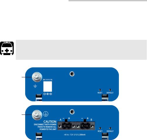
Grounding the BV10
The BV10 is equipped with a ground lug and hardware attached to the back of the unit. The grounding hardware consists of a washer with external teeth facing the unit and a locking nut. You will need to supply a #12 AWG wire.
WARNING
The BV10 DC version is intended to be grounded. Ensure that the unit is connected to earth ground during normal use.
AC unit ground lug and hardware
DC unit ground lug and hardware
To ground the BV10:
1.Loosen the locking nut on the grounding lug.
2.Using a #12 AWG wire, twist the wire around the lug so that it is touching the flat surface of the washer. The wire must be twisted between the washer and the locking nut.
3.Tighten the locking nut.
4.Connect the other end of the wire to the ground distribution network.
BV10-100 and BV10-1000 |
11 |

Getting Started
Connecting the Power
Connecting the BV10 using an AC/DC Power
Source
The typical output voltage of the external brick AC power supply is 9 V DC.
To connect the BV10 to an AC power source:
1.Connect the supplied AC power cord to the AC/DC adapter and the other end to an AC wall outlet.
2.Connect the other end of the power supply to the DC barrel power connector on the BV10.
Connecting the BV10 using a DC Power Source
The BV10 DC version is equipped with either +24 V DC or –48 V DC connector.
WARNING
Powering a BV10 +24 V DC unit with a –48 V power source will permanently damage the unit. The +24 V input range is 20-32 V.
Powering a BV10 –48 V DC unit with a +24 V power source will permanently damage the unit. The –48 V input range is –40 to –72 V.
To connect the BV10 to a DC power source:
1.Using 14-16 AWG copper insulated wires and the supplied connector, insert the two stripped wires into the connector and tighten the screws firmly. Either use non-stranded wire or crimp a ferrule onto the wire.
Be sure to respect the polarity.
The positive supply wire lead must be on the right side of the connector and the negative supply wire on the left side.
12 |
BV10 |
Getting Started
Connecting the Power
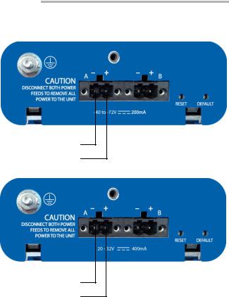
The following figures show the –48 V and +24 V DC units.
-
–48 V DC Unit
Supplied connector
Negative (–) supply wire lead on the left
Positive (+) supply wire lead on the right
-
+24 V DC Unit
Supplied connector
Negative (–) supply wire lead on the left
Positive (+) supply wire lead on the right
2.Connect the plug to one of the two DC input connectors on the BV10 unit and tighten the screws firmly.
BV10-100 and BV10-1000 |
13 |

Getting Started
Connecting the Power
3. Connect the other end of the wires to the DC power source.
CAUTION
The DC input feeds to the equipment must be protected by 20 A rated maximum breaker provided as part of the building installation.
Permanently connected equipment must have a switch or circuit-breaker for disconnection. If the switch is not part of the kit:
Include a switch or circuit-breaker in the installation.
The switch must be located easily, and placed near the equipment.
The switch must be specified as the disconnecting device for the equipment.
4.To add a redundant DC power source on the BV10, repeat step 1 through step 3.
WARNING
To avoid serious injuries as well as irreparable damages to your unit, ALWAYS TURN OFF BOTH DISCONNECT DEVICES BEFORE OPENING OR SERVICING THE UNIT.
14 |
BV10 |
4 Physical Interfaces, LEDs, and
Buttons
This section describes all connectors (ports), LEDs, and buttons available on the BV10-100 and BV10-1000 units.
BV10 Models
BV10-100
CONSOLE
TEST |
LAN |
BV10-1000
CONSOLE
TEST |
LAN |
Laser radiation emitted from this port when LASER LED is on.
BV10-100 and BV10-1000 |
15 |

Physical Interfaces, LEDs, and Buttons
Port Availability on BV10
Port Availability on BV10
Port |
Description |
|
Model |
||
|
|
|
|||
Label |
BV10-100 |
BV10-1000 |
|||
|
|||||
|
|
||||
|
|
|
|
|
|
|
|
|
|
|
|
TEST PORT |
10/100 Mbit/s electrical RJ45 Test port (10Base-T and 100Base-TX) |
X |
|
|
|
|
|
|
|
|
|
|
10/100/1000Mbit/s electrical RJ45 Test port (10Base-T, 100Base-TX |
|
|
X |
|
|
and 1000Base-T) |
|
|
|
|
|
|
|
|
|
|
|
1000 Mbit/s optical SFP Test port (1000Base-SX/LX/ZX; |
|
|
X |
|
|
850/1310/1550nm) |
|
|
|
|
|
|
|
|
|
|
LAN |
10/100 Mbit/s electrical Management port |
X |
|
X |
|
|
|
|
|
|
|
CONSOLE |
RS-232 DE-9F DCE (referred as DB9) Console port |
X |
|
X |
|
|
|
|
|
|
|
Connecting the TEST Port Interface
The BV10-100 provides an electrical 10/100 Mbit/s Ethernet Test interface while the BV10-1000 provides an electrical 10/100/1000 Mbit/s and an optical 1000 Mbit/s SFP laser Ethernet Test interfaces. The two BV10-1000 Test interfaces are mutually exclusive.
RJ45 Port
Connect the 10/100/1000 Mbit/s electrical interface to be tested to the RJ45 test port. The electrical ports is RJ45 for category 5 unshielded twisted pair (UTP). Refer to Ethernet Cables on page 102 for cable specifications.
Supported electrical rates are:
For BV10-100: 10 Mbit/s and 100 Mbit/s.
For BV10-1000: 10 Mbit/s, 100 Mbit/s, and 1000 Mbit/s.
16 |
BV10 |

Physical Interfaces, LEDs, and Buttons
Connecting the TEST Port Interface
SFP Port (BV10-1000)
The BV10-1000 provides an optional optical port for 1000Base-SX/LX/ZX testing capability. The optical port is a Small Form Factor Pluggable (SFP) slot type with LC connector.
Insert an SFP module into the SFP test port slot on the BV10. Refer to Optical Interface on page 95 for more information on supported SFP.
Carefully connect optical fibre cables to the SFP’s IN and OUT ports. To ensure good signal quality, make sure that the optical fibre connector is fully inserted into the optical connector port.
CAUTION
To prevent exceeding the maximum input power level please use an attenuator when a loopback configuration is used.
BV10-100 and BV10-1000 |
17 |

Physical Interfaces, LEDs, and Buttons
Connecting the Management Interfaces
Connecting the Management Interfaces
The management interface can be connected locally using the CONSOLE port or remotely using the LAN Port.
LAN Port
Connecting a typical management network to the 10/100 Mbit/s Ethernet LAN port provides remote access to the BV10 Command Line Interface (CLI) using either Telnet or SSH session.
To connect remotely to the BV10 using the LAN port, connect both the BV10 LAN port and the remote PC to the same Management network using a standard straight through Ethernet cable with RJ45 connectors.
18 |
BV10 |

Physical Interfaces, LEDs, and Buttons
Connecting the Management Interfaces
CONSOLE Port
Connecting a PC to the CONSOLE port provides local access to the BV10 using CLI commands.
The following figure shows the DB9 (RS-232 DE-9F DCE) pinouts as viewed from the front of the BV10.
The following table indicates the DB9 pinouts.
Pin Number |
Description |
|
|
|
|
1, 4, and 6 |
Connected together inside the BV10 |
|
|
7 and 8 |
Connected together inside the BV10 |
|
|
5 |
Signal ground |
|
|
2 |
TX (output of the BV10) |
|
|
3 |
RX (input of the BV10) |
|
|
9 |
Not internally connected |
|
|
DB9 casing |
Chassis ground |
|
|
To connect locally, connect a PC to the CONSOLE port using an RS-232 straight cable with a DB9 connector.
BV10-100 and BV10-1000 |
19 |

Physical Interfaces, LEDs, and Buttons
LEDs
LEDs
POWER
On (Green) indicates that the BV10 unit is receiving power from an external source.
Off indicates that the BV10 unit is not receiving power from the external source or the unit is damaged.
STATUS
On (Green) indicates that the link on the test port is up.
On (Red) indicates that the link on the test port is down.
Off indicates that the unit is not yet booted.
SPEED
Off indicates 10 Mbit/s
On (Green) indicates 100 Mbit/s
On (Amber) indicates 1000 Mbit/s (BV10-1000 only)
LINK/ACT (Electrical and Optical Ports)
On (Green) indicates that the link is up; there is no activity.
Off indicates that the link is down; there is no activity.
Blinking (Green) indicates that the link is up; there is activity.
LASER
Off indicates that the laser is off.
On (Red) indicates that the laser is on.
20 |
BV10 |

Physical Interfaces, LEDs, and Buttons
RESET and DEFAULT Buttons
RESET and DEFAULT Buttons
The RESET and DEFAULT buttons are recessed on the back of the BV10 to avoid accidental use.
-
RESET
DEFAULT
RESET Button
The RESET button is used to reboot the BV10. Press the RESET button once to reboot the BV10. While rebooting, the BV10 displays a series of messages if the unit is connected to a console.
The reboot command can also be used to reboot the BV10 (refer to reboot on page 45).
DEFAULT Button
The DEFAULT button is used to reset the BV10 to the factory default settings. Press the DEFAULT button once to reset the BV10 to its factory default settings then the unit reboots by itself.
BV10-100 and BV10-1000 |
21 |

5 Managing BV10 Verifier on BrixWorx
This chapter describes how to configure and use BV10 hardware on BrixWorx. It explains the CLI commands used to communicate with the BrixWorx registry and describes how to set up tests using the BrixWorx user interface.
Note: When the BV10 is used in a BrixWorx environment, you must use BrixWorx GUI rather than CLI prompt to manage the BV10 device. When you change a reflector to run or not through the CLI, this is not updated on the BrixWorx GUI Additional Services page. The GUI changes override the changes done using the CLI prompt.
Configuring BV10 Verifier for BrixWorx
Registry
The BV10 Verifier must be configured before you can use it in the BrixWorx system. Once the configuration of a BV10 Verifier is complete, you must add it to BrixWorx just like any other Verifier.
Configure the BV10 Verifier
To configure the BV10 Verifier for use in the BrixWorx system:
1.Access the CLI prompt using Telnet or SSH. To log on to the Telnet or SSH server, use the following login information:
Login ID: exfo Password: exfo123
The CLI prompt name contains the BV10 model number followed by (DEBUG). For example:
BV10-1000 (DEBUG)>
2.To configure the IP address of the local BrixWorx registry, type the following command:
BV10-1000 (DEBUG)> server discovery local IP address
BV10-100 and BV10-1000 |
23 |

Managing BV10 Verifier on BrixWorx
Configuring a Test
3. To configure the port of communication, type the following command:
BV10-1000 (DEBUG)> server discovery port value
The default port value is 80.
4. To save the new port value, type the following command:
BV10-1000 (DEBUG)> server discovery write
Add the BV10 to BrixWorx
Once you have configured a BV10, you must add it to BrixWorx.
Refer to the BrixWorx User Guide for more information on how to add the BV10 Verifier to the BrixWorx system.
Configuring a Test
Only a specific set of BrixWorx tests are supported by the BV10 Verifier. All tests supported on the BV10 Verifier are available through BrixWorx:
Ethernet OAM Handling
UDP Echo Responder
TWAMP Light Responder
Smart Loopback
SSH service
Telnet service
Refer to Test Applications on page 73 for more information on the tests supported on the BV10 Verifier.
24 |
BV10 |
 Loading...