


 Loading...
User Guide
FIP-400B
Fiber Inspection Probe and
ConnectorMax2 Mobile

Copyright © 2015 EXFO Inc. All rights reserved. No part of this publication may be reproduced, stored in a retrieval system or transmitted in any form, be it electronically, mechanically, or by any other means such as photocopying, recording or otherwise, without the prior written permission of EXFO Inc. (EXFO).
Information provided by EXFO is believed to be accurate and reliable. However, no responsibility is assumed by EXFO for its use nor for any infringements of patents or other rights of third parties that may result from its use. No license is granted by implication or otherwise under any patent rights of EXFO.
EXFO’s Commerce And Government Entities (CAGE) code under the North Atlantic Treaty Organization (NATO) is 0L8C3.
The information contained in this publication is subject to change without notice.
Trademarks
EXFO’s trademarks have been identified as such. However, the presence or absence of such identification does not affect the legal status of any trademark.
Units of Measurement
Units of measurement in this publication conform to SI standards and practices.
Patents
Feature(s) of this product is/are protected by pending design patents. Version number: 6.0.0.1
ii |
FIP-400B |

|
Contents |
|
|
Certification Information ........................................................................................................ |
v |
1 Introducing the FIP-400B Fiber Inspection Probe and |
|
|
|
ConnectorMax2 Mobile ................................................................................ |
1 |
|
Probe ...................................................................................................................................... |
1 |
|
Available Models .................................................................................................................... |
3 |
|
Probe Tips ............................................................................................................................... |
3 |
|
LED Indicators ......................................................................................................................... |
4 |
|
ConnectorMax2 Mobile Software .......................................................................................... |
6 |
|
Conventions ............................................................................................................................ |
7 |
2 |
Safety Information ....................................................................................... |
9 |
|
Other Safety Symbols on Your Unit ....................................................................................... |
10 |
|
Electrical Safety Information ................................................................................................. |
11 |
3 Setting up Your Fiber Inspection Probe and ConnectorMax2 Mobile ..... |
13 |
|
|
Preparing to Use the Mobile Application .............................................................................. |
13 |
|
Connecting or Disconnecting the Wireless Probe .................................................................. |
14 |
|
Changing the Fiber Inspection Probe Tip .............................................................................. |
17 |
|
Setting up Autonaming ........................................................................................................ |
18 |
|
Setting up Identification ....................................................................................................... |
22 |
|
Setting up the Increment ...................................................................................................... |
25 |
|
Setting Up Auto Capture ...................................................................................................... |
29 |
|
Selecting Test Configurations ............................................................................................... |
31 |
|
Modifying the File Format ..................................................................................................... |
36 |
|
Selecting the Sharing Application ......................................................................................... |
38 |
|
Sharing Data When No Connection Is Available .................................................................... |
40 |
|
Restoring to Default Settings ................................................................................................ |
43 |
4 |
Inspecting Fiber Ends ................................................................................. |
45 |
|
Inspecting Fiber Ends ........................................................................................................... |
45 |
|
Saving Files ........................................................................................................................... |
48 |
|
Managing Files ..................................................................................................................... |
52 |
|
Analyzing Captures ............................................................................................................... |
56 |
|
Transferring Results With Third-Party Applications ................................................................ |
60 |
Fiber Inspection Probe |
iii |

5 |
Maintenance ................................................................................................ |
65 |
|
General Maintenance ............................................................................................................ |
65 |
|
Recycling and Disposal (Applies to European Union Only) .................................................... |
65 |
|
Recharging the Battery ......................................................................................................... |
66 |
|
Replacing the Battery ............................................................................................................ |
68 |
6 |
Troubleshooting .......................................................................................... |
71 |
|
Solving Common Problems ................................................................................................... |
71 |
|
Contacting the Technical Support Group .............................................................................. |
74 |
|
Viewing Information About ConnectorMax2 Mobile ........................................................... |
75 |
|
Viewing Online Help ............................................................................................................. |
76 |
|
Transportation ...................................................................................................................... |
77 |
7 |
Warranty ...................................................................................................... |
79 |
|
General Information ............................................................................................................. |
79 |
|
Liability ................................................................................................................................. |
80 |
|
Exclusions ............................................................................................................................. |
80 |
|
Certification .......................................................................................................................... |
80 |
|
Service and Repairs ............................................................................................................... |
81 |
|
EXFO Service Centers Worldwide .......................................................................................... |
82 |
A |
Technical Specifications .............................................................................. |
83 |
B Fiber Inspection Probe Tip Compatibility Chart ....................................... |
85 |
|
Index ................................................................................................................. |
89 |
|
iv |
FIP-400B |

Certification Information
Certification Information
North America Regulatory Statement
This unit was certified by an agency approved in both Canada and the United States of America. It has been evaluated according to applicable North American approved standards for product safety for use in Canada and the United States.
Electronic test and measurement equipment is exempt from FCC part 15, subpart B compliance in the United States of America and from ICES-003 compliance in Canada. However, EXFO Inc. makes reasonable efforts to ensure compliance to the applicable standards.
The limits set by these standards are designed to provide reasonable protection against harmful interference when the equipment is operated in a commercial environment. This equipment generates, uses, and can radiate radio frequency energy and, if not installed and used in accordance with the user guide, may cause harmful interference to radio communications. Operation of this equipment in a residential area is likely to cause harmful interference in which case the user will be required to correct the interference at his own expense.
Modifications not expressly approved by the manufacturer could void the user's authority to operate the equipment.
Fiber Inspection Probe |
v |

Certification Information
Your unit comes with an internal wireless module and antenna for which the following information applies:
This equipment has been tested and found to comply with the limits for a Class A digital device, pursuant to Part 15 of the FCC Rules. Operation is subject to the following two conditions: (1) This device may not cause harmful interference, and (2) this device must accept any interference received, including interference that may cause undesired operation.
This device complies with Industry Canada license-exempt RSS standard(s). Operation is subject to the following two conditions: (1) this device may not cause interference, and (2) this device must accept any interference, including interference that may cause undesired operation of the device.
This device complies with the US/Canada portable RF exposure limit set forth for an uncontrolled environment and is safe for intended operation as described in this user documentation. The further RF exposure reduction can be achieved if the device can be kept as far as possible from the user’s body.
This device does not contain any user-serviceable components. Any unauthorized product changes or modifications will invalidate warranty and all applicable regulatory certifications and approvals.
vi |
FIP-400B |

Certification Information
European Community Declaration of Conformity
Warning: This is a class A product. In a domestic environment, this product may cause radio interference in which case the user may be required to take adequate measures.
Hereby, EXFO declares that the radio equipment type “Wide Band Data Transmission” is in compliance with Directive 2014/53/EU.
An electronic version of the complete declaration of conformity for your product is available on our website at www.exfo.com. Refer to the product’s page on the Web site for details.
The information about the Wi-Fi frequency bands is as follows:
Between the frequencies 2400.0 MHz - 2483.5 MHz. The maximum output power is 15 dBm.
This device is a 2.4 GHz wideband transmission system (transceiver), intended for use in all EU member states and EFTA countries, except in France and Italy where restrictive use applies.
In Italy, the end-user should apply for a license at the national spectrum authorities in order to obtain authorization to use the device for setting up outdoor radio links and/or for supplying access to telecommunications and/or network services.
This device may not be used for setting up radio links in France, and in some areas the RF output power may be limited to 10 mW EIRP in the frequency range of 2454 - 2483.5 MHz. For detailed information, the end-user should contact the national spectrum authority in France.
Fiber Inspection Probe |
vii |

1Introducing the FIP-400B Fiber Inspection Probe and
ConnectorMax2 Mobile
The FIP-400B Fiber Inspection Probe is a portable video microscope used to inspect fiber ends. Unlike traditional microscopes, the FIP-400B facilitates the examination of patchcord connectors and also hard-to-reach connectors on the back of patch panels and bulkhead adapters.
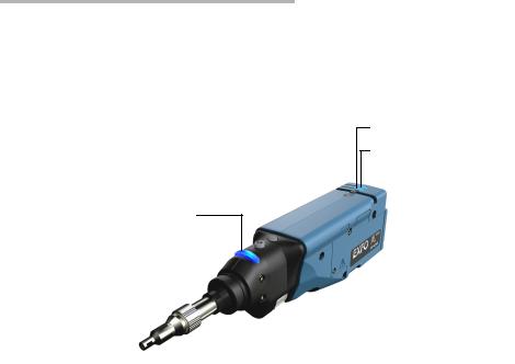
Probe
The FIP-400B is designed to be an intuitive, easy-to-use piece of equipment. This video microscope is used for inspecting fiber ends.
|
|
|
|
|
|
|
|
|
|
|
Magnification control |
||||||||
|
|
|
|
|
|
|
|
|
|
|
|||||||||
Capture control |
|
|
|
|
|
|
|
|
|
Battery LED |
|||||||||
|
|
|
|
|
|
|
|
|
|||||||||||
|
|
|
|
|
|
|
|
|
|
Wi-Fi LED |
|||||||||
|
|
|
|
|
|
|
|
|
|
||||||||||
|
|
|
|
|
|
|
|
|
|
|
|
|
|
|
|
||||
|
|
|
|
|
|
|
|
|
|
|
|
|
|
|
|
|
|
|
Micro USB adapter |
|
|
|
|
|
|
|
|
|
|
|
|
|
|
|
|
|
|
|
|
|
|
|
|
|
|
|
|
|
|
|
|
|
|
|
|
|
|
|
|
Status LED |
|
|
|
|
|
|
|
|
|
|
|
|
connector |
||||||
|
|
|
|
|
|
|
|
|
|
|
|
|
|
|
|
|
|
|
|
Retaining nut |
|
|
|
|
|
|
|
|
|
|
|
|
|
|
|
|
Battery compartment door |
||
|
|
|
|
|
|
|
|
|
|
|
|
|
|
|
|||||
|
|
|
|
|
|
|
|
|
|
|
|
|
|
|
|||||
|
|
|
|
|
|
|
|
|
|
|
|
|
|
|
|||||
|
|
|
|
|
|
|
|
|
|
|
|
|
|
|
|
||||
|
|
|
|
|
|
|
|
|
|
|
|
|
|
|
|||||
Interchangeable |
|
|
|
|
|
|
|
|
|
|
|
|
|
|
|
||||
|
|
|
|
|
|
|
|
|
|
|
|
|
|
|
|
||||
|
|
|
|
|
|
|
|
|
|
|
|
|
|
||||||
adapter tips |
|
|
|
|
|
|
|
|
|
|
|
|
|
||||||
|
|
|
|
|
|
|
|
Focus |
|||||||||||
The focus knob can be turned in either direction to focus the image.
The magnification control button allows you to shift between three levels of magnification. When pressed for one second, it activates the auto focus.
Fiber Inspection Probe |
1 |

Introducing the FIP-400B Fiber Inspection Probe and ConnectorMax2 Mobile
Probe
The capture control button allows you to capture an image, perform an analysis, or return to the Live Video mode.
The retaining nut holds tips securely in place, ensuring they are always fastened in the correct position.
The status LED gives you information about the probe or the analysis results.
The interchangeable adapter tips give you the possibility to use various tips depending on the type of connector you are inspecting.
The micro USB adapter connector recharges the battery of the probe when it is low. You can recharge the battery with the provided USB cable and the adapter/charger that you connect to a power outlet. You can also use the provided USB cable alone that you connect to a USB port of a computer.
When the probe is connected to a power outlet or to a USB port, it still works via Wi-Fi.
The battery compartment door is for battery replacement.
The probe comes equipped with a protective cap that fits over basic tips; therefore, you do not need to remove the tip before putting the cap on.
2 |
FIP-400B |
Introducing the FIP-400B Fiber Inspection Probe and ConnectorMax2 Mobile
Available Models
Available Models
The features available for your probe are automatically detected when you connect it to your smart device. The table below shows which feature is available for each model.
Models |
Inspection |
Auto analysis |
Auto centering |
Auto focus |
Auto capture |
|
|
|
|
|
|
|
|
|
|
|
|
FIP-425B |
X |
X |
X |
- |
- |
|
|
|
|
|
|
FIP-435B |
X |
X |
X |
X |
X |
|
|
|
|
|
|
Note: When the internal temperature of the FIP-435B is too low, the probe performs a warm-up that can last up to a minute.
Probe Tips
The FIP-400B comes with two interchangeable tips included in two different packages (UPC or APC). Additional models are also available.
UPC package:
FIPT-400-FC-SC: FC-SC Bulkhead tip
FIPT-400-U25M: Universal patchcord tip (2.5 mm ferrule)
APC package:
FIPT-400-SC-APC: SC APC tip for bulkhead adapter
FIPT-400-U25MA: Universal patchcord tip for 2.5 mm ferrules
Other tip models are available for various bulkhead adapters and patchcord connectors. For more information about tips and their use, see the Fiber Inspection Probe Tip Compatibility Chart on page 85, or visit the EXFO Web site.
Fiber Inspection Probe |
3 |
Introducing the FIP-400B Fiber Inspection Probe and ConnectorMax2 Mobile
LED Indicators
LED Indicators
The LED located on the probe gives you information about the probe or the analysis results.
Battery LED
Wi-Fi LED
Status LED
Status LED |
Status |
|
|
|
|
Flashing blue |
Processing in progress |
|
|
Flashing red |
There is a problem with the probe. |
|
Follow the instructions on screen. |
|
The auto focus is in timeout |
|
There is an analysis error |
|
|
Blue |
The probe is ready and operational |
|
|
Red |
In Capture mode, current FIP result |
|
status is Fail |
|
|
Green |
In Capture mode, current FIP result |
|
status is Pass |
|
|
4 |
FIP-400B |
Introducing the FIP-400B Fiber Inspection Probe and ConnectorMax2 Mobile
|
|
LED Indicators |
|
|
|
|
|
|
Battery LED |
|
Status |
|
|
|
|
|
|
Flashing blue |
|
USB connected, battery charging |
|
|
|
Blue |
|
USB connected, battery fully charged |
|
|
|
Red |
|
Battery error (only visible when |
|
|
connected to a USB cable) |
|
|
|
Flashing yellow |
|
USB connected, battery not charging |
|
|
because the battery temperature does |
|
|
not allow the battery to charge |
|
|
|
Yellow |
|
USB not connected, critical battery |
|
|
level |
|
|
|
Not lit |
|
USB not connected, battery above low |
|
|
level |
|
|
|
|
|
|
Wi-Fi LED |
|
Status |
|
|
|
|
|
|
Blue |
|
Ready to transmit |
|
|
Wireless transmission in progress |
|
|
|
Red |
|
Transmission error |
|
|
|
Not lit |
|
Probe is off |
|
|
OR |
|
|
Probe is initializing |
|
|
|
Fiber Inspection Probe |
5 |

Introducing the FIP-400B Fiber Inspection Probe and ConnectorMax2 Mobile
ConnectorMax2 Mobile Software
ConnectorMax2 Mobile Software
ConnectorMax2 Mobile is the application used to view the fiber inspections. You can also use specific test configurations and analyze the fibers automatically upon capturing a picture.
Archive icon
User Preferences
Can be found in the menu button depending on the smart device used.
Auto focus
Battery status
Name of the file resulting from the autonaming
6 |
FIP-400B |

Introducing the FIP-400B Fiber Inspection Probe and ConnectorMax2 Mobile
Conventions
Conventions
Before using the product described in this guide, you should understand the following conventions:
WARNING
Indicates a potentially hazardous situation which, if not avoided, could result in death or serious injury. Do not proceed unless you understand and meet the required conditions.
CAUTION
Indicates a potentially hazardous situation which, if not avoided, may result in minor or moderate injury. Do not proceed unless you understand and meet the required conditions.
CAUTION
Indicates a potentially hazardous situation which, if not avoided, may result in component damage. Do not proceed unless you understand and meet the required conditions.
IMPORTANT
Refers to information about this product you should not overlook.
Note: The appearance and the orientation (portrait or landscape) of the application may vary depending on the smart device used.
Fiber Inspection Probe |
7 |

2 Safety Information
WARNING
Do not install or terminate fibers while a light source is active. Never look directly into a live fiber and ensure that your eyes are protected at all times.
WARNING
The use of controls, adjustments and procedures, namely for operation and maintenance, other than those specified herein may result in hazardous radiation exposure or impair the protection provided by this unit.
IMPORTANT
When you see the following symbol on your unit |
, make sure |
that you refer to the instructions provided in your user |
|
documentation. Ensure that you understand and meet the required conditions before using your product.
IMPORTANT
Other safety instructions relevant for your product are located throughout this documentation, depending on the action to perform. Make sure to read them carefully when they apply to your situation.
CAUTION
Do not use the fiber probe outdoors in wet locations.
Fiber Inspection Probe |
9 |

Safety Information
Other Safety Symbols on Your Unit
Other Safety Symbols on Your Unit
One or more of the following symbols may also appear on your unit.
Symbol |
Meaning |
|
|
|
|
|
Direct current |
|
|
|
Alternating current |
|
|
|
The unit is equipped with an earth (ground) terminal. |
|
|
|
The unit is equipped with a protective conductor terminal. |
|
|
|
The unit is equipped with a frame or chassis terminal. |
|
|
|
On (Power) |
|
|
|
Off (Power) |
|
|
OR |
On/Off (Power) |
|
|
|
Fuse |
|
|
10 |
FIP-400B |

Safety Information
Electrical Safety Information
Electrical Safety Information
If you need to ensure that the unit is completely turned off, disconnect the power cable and remove the battery.
WARNING
Use the external electrical power supply indoors only.
Position the unit so that the air can circulate freely around it.
Operation of any electrical instrument around flammable gases or fumes constitutes a major safety hazard.
To avoid electrical shock, do not operate the unit if any part of the outer surface (covers, panels, etc.) is damaged.
Only authorized personnel should carry out adjustments, maintenance or repair of opened units under voltage. A person qualified in first aid must also be present. Do not replace any components while the power cable and battery are connected.
Capacitors inside the unit may be charged even if the unit has been disconnected from its electrical supply.
Use only the listed and certified AC adapter/charger provided by EXFO with your unit. It provides reinforced insulation between primary and secondary, and is suitably rated for the country where the unit is sold.
Fiber Inspection Probe |
11 |

Safety Information
Electrical Safety Information
|
Equipment Ratings |
|
|
|
|
|
|
|
Temperature |
Unit powered by batteries: -10 °C to 40 °C |
|
Operation |
(14 °F to 104 °F) |
|
Unit connected to USB adapter: 0 °C to 40 °C |
||
|
||
|
(32 °F to 104 °F) |
|
Storage |
Unit without batteries: -40 °C to 70 °C |
|
|
(-40 °F to 158 °F) |
|
|
Unit with batteries: -20 °C to 60 °C |
|
|
(-4 °F to 140 °F) |
|
|
|
|
Relative humiditya |
unit: 95 % non-condensing |
|
|
USB adapter: 5 % to 95 % for storage and 8 % to 90 % |
|
|
for operating temperature |
|
|
|
|
Maximum operation altitude |
2000 m (6562 ft) (unit connected to USB adapter) |
|
|
3000 m (9843 ft) (unit operated from batteries) |
|
|
|
|
Pollution degree |
2 (unit connected to external power supply) |
|
|
3 (unit operated from batteries)b |
|
Overvoltage category |
unit: I |
|
|
AC adapter: II |
|
|
|
|
Measurement category |
Not rated for measurement categories II, III, or IV |
|
|
|
|
Input powerc |
unit: 5 VDC; 1.8 A |
|
|
USB adapter: 100 - 240 Vac; 50 Hz to 60 Hz; |
|
|
0.4 A Max |
|
|
|
a.Measured in 0 °C to 31 °C (32 °F to 87.8 °F) range, decreasing linearly to 50 % at 40 °C (104 °F).
b.Equipment must be normally protected against exposure to direct sunlight, precipitation and full wind pressure.
c.Not exceeding ± 10 % of the nominal voltage.
12 |
FIP-400B |
3Setting up Your Fiber Inspection Probe and
ConnectorMax2 Mobile
When you receive your wireless probe, and before you start working, you need to download the ConnectorMax2 Mobile application on your smart device. The application is available for smart devices supporting
Android 4.2, mainly Samsung Galaxy Note 3 and 4, as well as Samsung Galaxy Tab 4 with an 8-inch screen.
You can change various settings in ConnectorMax2 Mobile, such as the automated file name or the way you want to share files with third party applications. These settings are kept for future work sessions.
Preparing to Use the Mobile Application
Before you start working with your wireless probe, there are two steps to perform.
You need to install ConnectorMax2 Mobile on your smart device.
IMPORTANT
The ConnectorMax2 Mobile application is available for free in Google Play Store. You need to have a Google account to download the application. For more information, refer to www.google.com.
Once the application is installed, you have to connect your wireless probe by Wi-Fi.
When your wireless probe is connected, it is added to the list of the available probes. It remains available for future tests.
Note: You need to have access to an external Wi-Fi network to install ConnectorMax2 Mobile. The Wi-Fi needs to be set to ON on your smart device.
Fiber Inspection Probe |
13 |

Setting up Your Fiber Inspection Probe and ConnectorMax2 Mobile
Connecting or Disconnecting the Wireless Probe
To install ConnectorMax2 Mobile:
1.Ensure you have access to an Internet connection.
2.Tap the Google Play Store icon.
3.In the Google Play Store (or Play Store) application, search for EXFO or ConnectorMax2 Mobile.
4.Follow the instructions on-screen.
Once the ConnectorMax2 Mobile is installed, you can now activate the wireless probe.
Connecting or Disconnecting the Wireless Probe
When the ConnectorMax2 Mobile is installed on your smart device, you have to connect your wireless probe by Wi-Fi. When your wireless probe is connected it is added to the list of the available probes. It remains available for future tests.
You have to disconnect the probe first if you want to perform the following:
work with another probe
use the probe with another smart device
share files with third-party applications
14 |
FIP-400B |

Setting up Your Fiber Inspection Probe and ConnectorMax2 Mobile
Connecting or Disconnecting the Wireless Probe
To connect the wireless probe:
1.Ensure the power saving mode is disabled on your smart device.
2.Turn on the probe by pressing the ON button.
3.Ensure the Wi-Fi is activated on your smart device.
4.Start the ConnectorMax2 Mobile application.
5.Select the wireless probe you want to work with.
Note: When a wireless probe is selected, the 3G, 4G and LTE communications are disabled automatically.
Note: The probes are identified by their serial numbers and type.
Note: The probe can be selected from the Wi-Fi configuration on the smart device.
Fiber Inspection Probe |
15 |

Setting up Your Fiber Inspection Probe and ConnectorMax2 Mobile
Connecting or Disconnecting the Wireless Probe
To disconnect the wireless probe: 1. From the main window, tap  .
.
Note: Depending on the smart device you are using, the application settings can be found in the menu button instead.
2. Select Disconnect probe.
16 |
FIP-400B |
Setting up Your Fiber Inspection Probe and ConnectorMax2 Mobile
Changing the Fiber Inspection Probe Tip
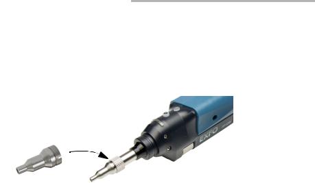
Changing the Fiber Inspection Probe Tip
You can use various tips depending on the type of connector you are inspecting. For more information about tips you can use, see the Fiber Inspection Probe Tip Compatibility Chart on page 85, or contact your vendor for additional information.
To change a tip:
1.Untighten the tip’s retaining nut.
2.Remove the tip.
3.Insert a new tip.
4.Adjust the tip to the notch.
5.Retighten the retaining nut.
Fiber Inspection Probe |
17 |

Setting up Your Fiber Inspection Probe and ConnectorMax2 Mobile
Setting up Autonaming
Setting up Autonaming
The autonaming feature is useful to make a relevant naming scheme for your tests. This also ensures that you do not overwrite files by mistake. You can select which item goes in the file name, as well as the type of separator you want to use in between.
A preview is available to show you the final output of the file name.
In Live Video mode, the autonaming parameters can be set. You will only see the parameters for the current and next capture (when the test is done but not saved yet), or for the next capture only (test is not done yet).
Otherwise, the parameters will not be displayed.
In Capture and Archive modes, it is possible to change the name of the file without changing the settings.
18 |
FIP-400B |

Setting up Your Fiber Inspection Probe and ConnectorMax2 Mobile
Setting up Autonaming
To configure the automatic file naming:
1. From the main window, tap the  at the end of the Identification row.
Note: You can also tap the  at the end of the Measurement Name row.
Fiber Inspection Probe |
19 |

Setting up Your Fiber Inspection Probe and ConnectorMax2 Mobile
Setting up Autonaming
2. Select the Autonaming tab.
3. Move the identifiers from the Inactive Identifiers to the Active Identifiers space by tapping . You can remove the identifiers by tapping . You can also move the identifiers with the drag and drop gesture.
Note: Only the identifiers with values are displayed.
4.Under Filename Edition, you can customize the information displayed next to Custom Filename.
Note: You can edit information either with the virtual keyboard or with the microphone. A microphone is part of the virtual keyboard on your smart device.
20 |
FIP-400B |

Setting up Your Fiber Inspection Probe and ConnectorMax2 Mobile
Setting up Autonaming
5.If you want to select the separator in the automatic numbering section, tap the line next to Separator.
5a. Navigate through the separators by scrolling through the words that are greyed.
5b. Tap OK to confirm your choice.
6.Tap  to confirm your new settings and to return to the main window. The new settings will apply the next time you perform a capture.
Fiber Inspection Probe |
21 |

Setting up Your Fiber Inspection Probe and ConnectorMax2 Mobile
Setting up Identification
Setting up Identification
In order to have information on the tests to be performed, it is possible to customize some fields such as the cable ID, the fiber ID, the location (A and/or B), the Connector ID, or the Frame.
To configure the identification:
1. From the main window, tap the  at the end of the Identification row.
Note: You can also tap the  at the end of the Measurement Name row.
22 |
FIP-400B |
Loading...