

Page 1
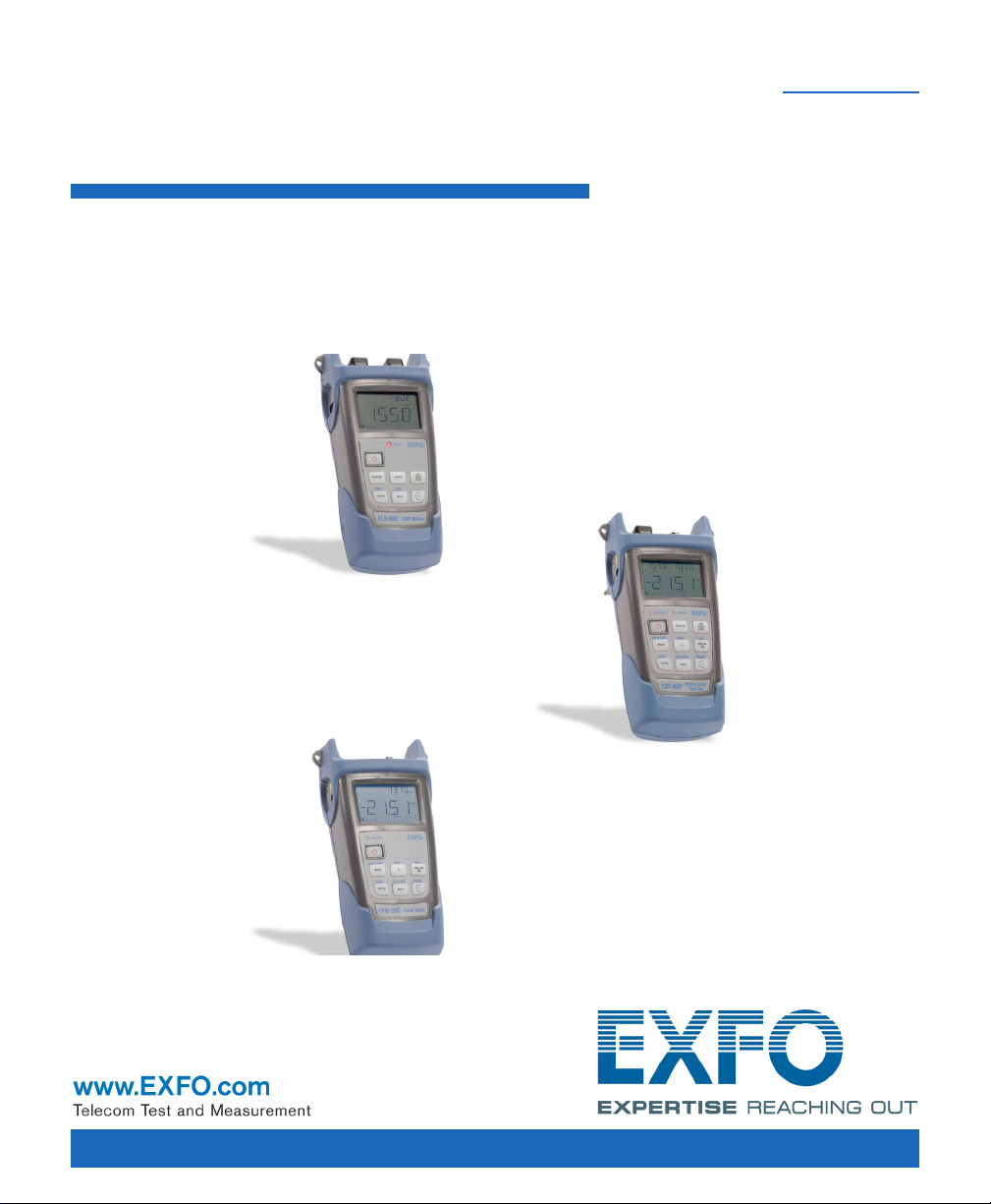
FPM/FLS/FOT-600
Power Meter/Light Source/
Optical Loss Test Set
User Guide
Page 2

Copyright © 2003–2013 EXFO Inc. All rights reserved. No part of this
publication may be reproduced, stored in a retrieval system or transmitted
in any form, be it electronically, mechanically, or by any other means such
as photocopying, recording or otherwise, without the prior written
permission of EXFO Inc. (EXFO).
Information provided by EXFO is believed to be accurate and reliable.
However, no responsibility is assumed by EXFO for its use nor for any
infringements of patents or other rights of third parties that may result from
its use. No license is granted by implication or otherwise under any patent
rights of EXFO.
EXFO’s Commerce And Government Entities (CAGE) code under the North
Atlantic Treaty Organization (NATO) is 0L8C3.
The information contained in this publication is subject to change without
notice.
Trademarks
EXFO’s trademarks have been identified as such. However, the presence
or absence of such identification does not affect the legal status of any
trademark.
Units of Measurement
Units of measurement in this publication conform to SI standards and
practices.
Patents
EXFO’s Universal Interface is protected by US patent 6,612,750.
Version number: 7.0.0
ii FPM/FLS/FOT-600
Page 3

Contents
Certification Information ........................................................................................................v
1 Introducing the FPM/FLS/FOT-600 ................................................................ 1
Main Features ........................................................................................................................ 1
Power Sources ....................................................................................................................... 3
Typical Applications ............................................................................................................... 4
Conventions ........................................................................................................................... 5
2 Safety Information ....................................................................................... 7
Laser Safety Information
(FLS-600 and FOT-600 without VFL) ................................................................................. 8
Laser Safety Information (Units with VFL) .............................................................................. 9
Electrical Safety Information ..................................................................................................9
3 Getting Started .......................................................................................... 11
Turning the Unit On and Off ................................................................................................ 11
Activating Automatic Shutdown (Auto-Off) ......................................................................... 13
Activating the Backlight .......................................................................................................14
Accessing and Navigating Setup Menus .............................................................................. 14
Installing the EXFO Universal Interface (EUI) ........................................................................ 16
Cleaning and Connecting Optical Fibers .............................................................................. 17
4 Measuring Power or Loss (FPM-600 and FOT-600) ................................... 19
Nulling Electrical Offsets ...................................................................................................... 19
Setting Power Correction Factor .......................................................................................... 20
Defining a List of Favorite Wavelengths ............................................................................... 22
Referencing Your Power Meter to a Source .......................................................................... 24
Measuring Power or Loss ..................................................................................................... 27
Automatically Detecting Wavelength ................................................................................... 29
Activating Hold Min/Max Power Mode ................................................................................ 30
Setting Pass/Fail Thresholds ................................................................................................. 31
5 Using a Light Source (FLS-600 and FOT-600) or VFL ................................. 33
Defining a List of Favorite Wavelengths ............................................................................... 33
Activating/Deactivating a Light Source or VFL ...................................................................... 34
Modulating the Source Signal .............................................................................................. 34
Using Auto-Switching Mode ................................................................................................ 35
Sending Source Power Value with Signal ............................................................................. 36
Power Meter/Light Source/Optical Loss Test Set iii
Page 4

6 Saving and Recalling Power/Loss Values ...................................................39
Setting Autonaming Scheme ............................................................................................... 39
Saving, Recalling and Deleting Data .................................................................................... 40
Transferring Data to a Computer ......................................................................................... 43
7 Maintenance ................................................................................................45
Cleaning EUI Connectors ..................................................................................................... 45
Cleaning Fixed Connectors ................................................................................................... 48
Cleaning VFL-Type Connectors ............................................................................................. 50
Cleaning Detector Ports ....................................................................................................... 51
Recharging and Replacing the Battery ................................................................................. 52
Recalibrating the Unit .......................................................................................................... 54
Recycling and Disposal (Applies to European Union Only) ................................................... 54
8 Troubleshooting ..........................................................................................55
Solving Common Problems .................................................................................................. 55
Reverting Unit to Factory Settings ....................................................................................... 56
Error Codes and Descriptions ............................................................................................... 57
Contacting the Technical Support Group ............................................................................. 58
Transportation ..................................................................................................................... 59
9 Warranty ......................................................................................................61
General Information ............................................................................................................61
Liability ................................................................................................................................ 62
Exclusions ............................................................................................................................ 63
Certification ......................................................................................................................... 63
Service and Repairs .............................................................................................................. 64
EXFO Service Centers Worldwide ......................................................................................... 65
A Technical Specifications ..............................................................................67
FPM-600 .............................................................................................................................. 67
FLS-600 ................................................................................................................................ 68
FOT-600 ............................................................................................................................... 69
iv FPM/FLS/FOT-600
Page 5

Certification Information
Certification Information
North America Regulatory Statement
This unit was certified by an agency approved in both Canada and the
United States of America. It has been evaluated according to applicable
North American approved standards for product safety for use in Canada
and the United States.
Electronic test and measurement equipment is exempt from FCC part 15,
subpart B compliance in the United States of America and from ICES-003
compliance in Canada. However, EXFO Inc. makes reasonable efforts to
ensure compliance to the applicable standards.
The limits set by these standards are designed to provide reasonable
protection against harmful interference when the equipment is operated in
a commercial environment. This equipment generates, uses, and can
radiate radio frequency energy and, if not installed and used in accordance
with the user guide, may cause harmful interference to radio
communications. Operation of this equipment in a residential area is likely
to cause harmful interference in which case the user will be required to
correct the interference at his own expense.
Modifications not expressly approved by the manufacturer could void the
user's authority to operate the equipment.
Power Meter/Light Source/Optical Loss Test Set v
Page 6

Certification Information
EN 61010-1:2010 Edition 3.0
Safety requirements for electrical equipment for measurement,
control, and laboratory use
EN 61326-1:2006
Electrical equipment for measurement, control and laboratory use –
EMC requirements
EN 60825-1:2007 Edition 2.0
Safety of laser products – Part 1: Equipment classification and
requirements
European Community Declaration of Conformity
DECLARATION OF CONFORMITY
Application of Council Directive(s):
And their amendments
Manufacturer’s Name and Address:
400 Godin Avenue Winchester House
Quebec City, Quebec School Lane, Chandlers Ford
G1M 2K2, CANADA SO53 4DG, UK
Tel.: +1 418 683-0211 Tel.: +44 2380 246 800
Equipment Type/Environment:
Trade Name/Model No.:
Standard(s) to which Conformity is declared:
1999/5/EC – The R&TTE Directive
2011/65/UE – Restriction of the use of certain hazardous substances (RoHS)
EXFO Inc. EXFO Europe Ltd.
Test & Measurement / Industrial
OLTS / FOT-600, Power Meter / FPM-600 & Light Source / FLS-600
– Part 1: General requirements
I, the undersigned, hereby declare that the equipment specified above conforms to the above Directive and Standards.
Manufacturer:
Stephen Bull, E. Eng
Vice-President Research and Development
400 Godin Avenue,
Quebec City, Quebec
G1M 2K2 CANADA
November 12, 2012
vi FPM/FLS/FOT-600
– Part 1: General requirements
Page 1 of 1
Page 7
1 Introducing the
FPM/FLS/FOT-600
This user guide covers the following products (unless otherwise specified,
descriptions apply to all):
FPM-600 Power Meter
FLS-600 Light Source
FOT-600 Optical Loss Test Set: combines both a power meter and a
light source
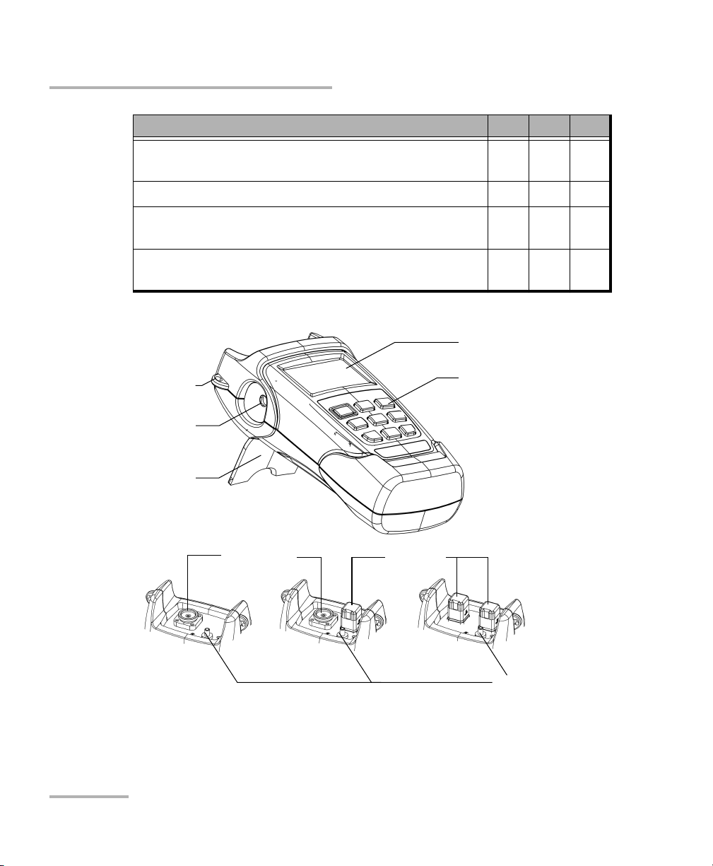
Main Features
FPM FLS FOT
Ge or GeX detector with 44 and 45 calibrated
wavelengths respectively
Absolute power and link loss measurements X X
Editable list of favorite power meter wavelengths X X
Editable list of favorite source wavelengths X X
Automatic wavelength detection X X
No offset nulling of detectors required in normal
operation
Multiple source configurations on a single port
[FOT-600] or on one or two ports [FLS-600]
Optional visual fault locator X
Transmission of editable power value with source’s
signal for automatic reference with compatible power
meter
Transmission of wavelength to compatible power
meter in automatic wavelength or auto-switching
mode
XX
XX
XX
XX
XX
Power Meter/Light Source/Optical Loss Test Set 1
Page 8
Introducing the FPM/FLS/FOT-600
Main Features
FPM FLS FOT
Modulated signal emission or detection (270 Hz, 1 kHz
XXX
and 2 kHz) compatible with other EXFO units
Data storage on unit and USB transfer to a computer X X
User-configurable pass/fail thresholds with LED
XX
indicator
Automatic shutdown after 10 minutes of idle time
XXX
(auto-off)
LCD display
Shoulder strap
eyelet
DC
connector
Stand
Power meter
detector port
Light source
ports
Keypad
(FOT-600 shown)
FOT-600 FLS-600FPM-600
Visual fault
locator port
2 FPM/FLS/FOT-600
Page 9
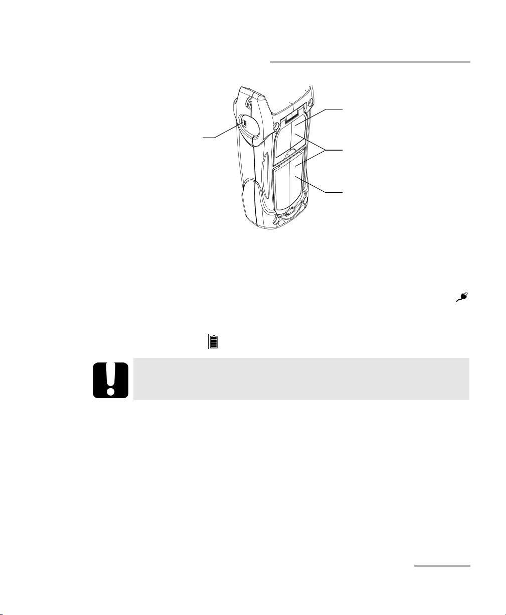
Introducing the FPM/FLS/FOT-600
Power Sources
Safety label
and serial number
USB connector
(under the stand)
Quick reference
labels
Battery
compartment
Power Sources
The units operate with the following power sources:
AC adapter (connected to standard power outlet—indoor use only)
Compatible car outlet adapter available upon request.
Li-Ion rechargeable battery (automatically takes over if you unplug the
AC adapter)
IMPORTANT
If the battery level becomes too low, the unit turns itself off.
Note: When it is connected with the AC adapter/charger, the unit will function
even if the battery is not present.
Possible to switch from AC adapter/charger to battery power or vice
versa without affecting operation.
The battery recharges automatically when the AC adapter/charger is
connected.
Power Meter/Light Source/Optical Loss Test Set 3
Page 10

Introducing the FPM/FLS/FOT-600
Typical Applications
Typical Applications
Transmitter power measurements (dBm and W)
Fiber-link loss testing (dB)
Component insertion-loss testing (dB)
Fiber identification with 270-Hz, 1-kHz and 2-kHz signals
Fiber installation and maintenance applications
FTTx: testing of passive optical networks (PONs)
4 FPM/FLS/FOT-600
Page 11

Introducing the FPM/FLS/FOT-600
Conventions
Before using the product described in this guide, you should understand
the following conventions:
WARNING
Indicates a potentially hazardous situation which, if not avoided,
could result in death or serious injury. Do not proceed unless you
understand and meet the required conditions.
CAUTION
Indicates a potentially hazardous situation which, if not avoided,
may result in minor or moderate injury. Do not proceed unless you
understand and meet the required conditions.
CAUTION
Indicates a potentially hazardous situation which, if not avoided,
may result in component damage. Do not proceed unless you
understand and meet the required conditions.
Conventions
IMPORTANT
Refers to information about this product you should not overlook.
Power Meter/Light Source/Optical Loss Test Set 5
Page 12

Page 13

2 Safety Information
WARNING
Do not install or terminate fibers while a light source is active.
Never look directly into a live fiber and ensure that your eyes are
protected at all times.
WARNING
The use of controls, adjustments and procedures other than those
specified herein may result in exposure to hazardous situations or
impair the protection provided by this unit.
IMPORTANT
When you see the following symbol on your unit , make sure
that you refer to the instructions provided in your user
documentation. Ensure that you understand and meet the required
conditions before using your product.
Power Meter/Light Source/Optical Loss Test Set 7
Page 14
Safety Information
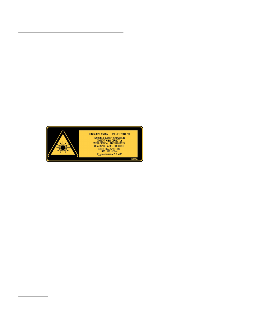
Laser Safety Information (FLS-600 and FOT-600 without VFL)
Laser Safety Information
(FLS-600 and FOT-600 without VFL)
Your instrument is a Class 1M laser product in compliance with standards
IEC 60825-1 2007 and 21 CFR 1040.10. Invisible laser radiation may be
encountered at the output port.
The product is safe under reasonably foreseeable conditions of operation
but it may be hazardous if you use optics within a diverging or collimated
beam. Do not view directly with optical instruments.
The following label(s) indicate that the product contains a Class 1M source:
8 FPM/FLS/FOT-600
Page 15
Safety Information
Laser Safety Information (Units with VFL)
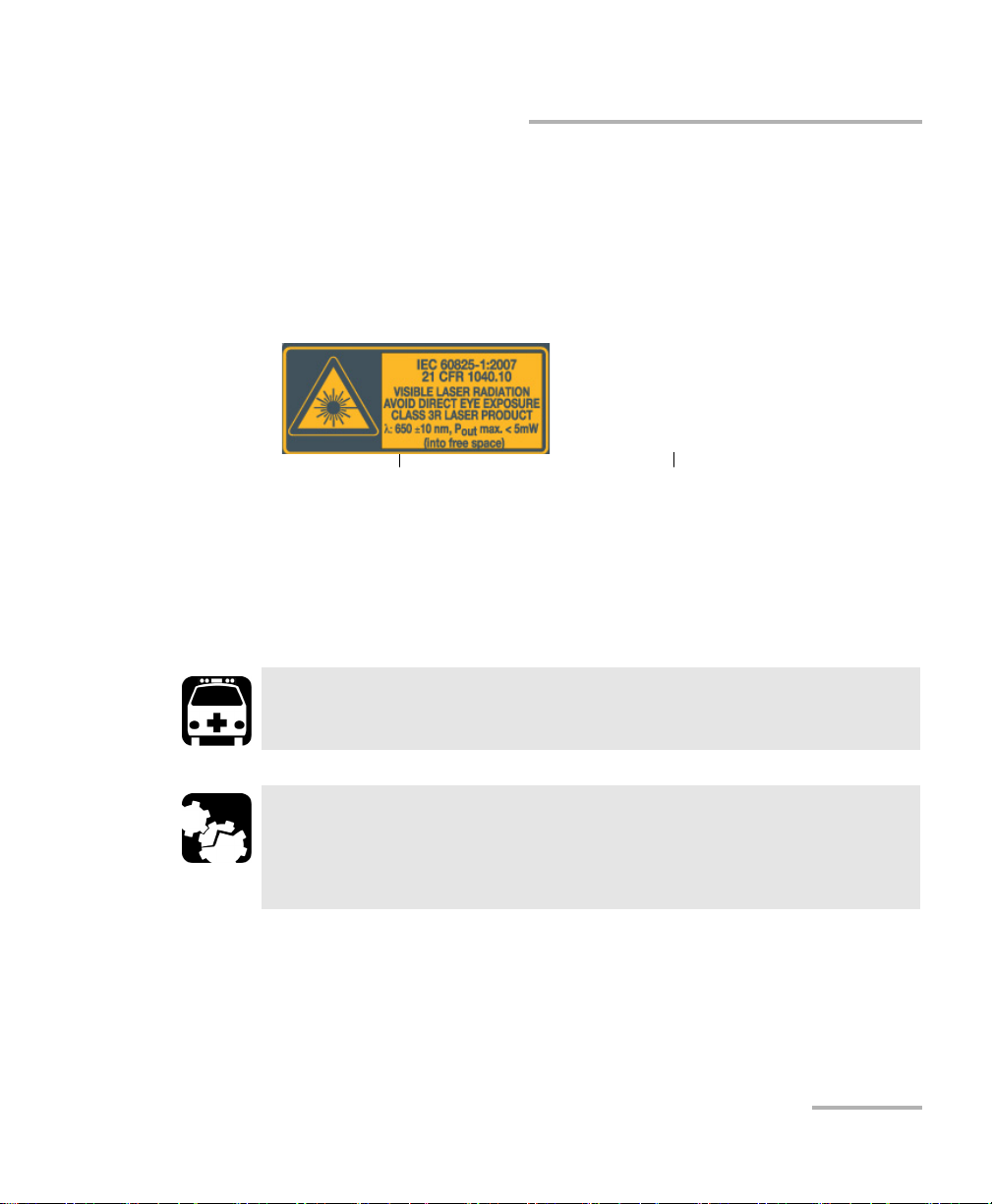
Laser Safety Information (Units with VFL)
Your instrument is a Class 3R laser product in compliance with standards
IEC 60825-1 2007 and 21 CFR 1040.10. It is potentially harmful in direct
intrabeam viewing.
The following label(s) indicate that the product contains a Class 3R source:
VFL LASER APERTURE
Affixed to back
(under the stand)
Indicated on
connector panel
Electrical Safety Information
The AC adapter/charger provided with this unit is specifically designed to
work with your product.
WARNING
Use only accessories that meet EXFO expectations.
CAUTION
EXFO guarantees the specifications and viability of the products
ONLY if they are used with chargers and batteries provided by
EXFO.
Power Meter/Light Source/Optical Loss Test Set 9
Page 16
Safety Information
Electrical Safety Information
Temperature
Operation
Storage
Relative humidity
unit
AC adapter
Equipment Ratings
-0 °C to 40 °C (32 °F to 104 °F)
-40 °C to 70 °C (-40 °F to 158 °F)
a
95 % non-condensing
0 % to 80 % non-condensing
Maximum operation
5000 m (6562 ft)
altitude
Pollution degree 2 (connected to AC mains)
3 (powered by batteries)
b
c
Overvoltage category II
Input power
unit
AC adapter
d
9 V; 9 W
120 V, 14.4 W, 60 Hz
230 V, 17 W, 50 Hz
a. Measured in 0 °C to 31 °C (32 °F to 87.8 °F) range, decreasing linearly to 50 % at 40 °C
(104 °F)
b. For indoor use only.
c. Equipment is normally protected against exposure to direct sunlight, precipitations and
full wind pressure.
d. Not exceeding ± 10 % of the nominal voltage
10 FPM/FLS/FOT-600
Page 17

3 Getting Started
Turning the Unit On and Off
When you turn off the FPM-600 or the FOT-600, it saves the current
wavelength, unit and reference power. It also saves the Hold Min/Max
power mode if activated.
IMPORTANT
If you remove batteries (and the AC adapter is unplugged), the unit
will turn off without saving the above values.
If batteries are low (and the AC adapter is unplugged), the unit will
save the above values and turn off.
Note: Offset nulling values are always returned to factory settings.
To turn on the unit:
Press . The unit displays EXFO Inc. for a few seconds. You may use it
immediately under normal conditions.
To turn off the unit:
From normal operating mode, hold down a few seconds.
WARNING
When the ACTIVE LED on your unit is on, the laser source is active
and emitting light. Do not look directly into a live fiber, and ensure
that your eyes are protected at all times.
Power Meter/Light Source/Optical Loss Test Set 11
Page 18
Getting Started
Turning the Unit On and Off
LED Indicators
FPM/FOT-600:
Whether the test passed or failed
according to the thresholds
Source wavelength (FOT)
Fiber number
Correction factor activated
AC adapter plugged in
Batteries in use
(with level)
Auto-off activated
FLS/FOT-600:
The laser source is active.
Display
Power meter wavelength or
reference power (FPM/FOT)
Value included in favorites list
Modulation values
Measured power/loss (FPM/FOT)
Active source wavelength (FLS)
Power meter mode
Data storage or recall modes
12 FPM/FLS/FOT-600
Page 19
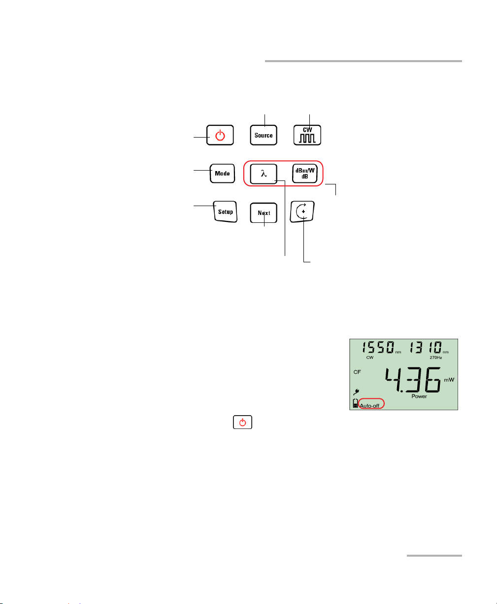
Keypad
Getting Started
Activating Automatic Shutdown (Auto-Off)
PRESS: Toggles between all available
wavelengths plus VFL (optional)
Turns unit on/off
Controls auto-off
Exits special modes
PRESS: Switches between
Power, Hold Min, Hold Max
HOLD: Backlight on/off
PRESS: Enters setup
menu
HOLD: Erases data
PRESS:Switches between wavelengths
PRESS:Next value
HOLD: Stores or
edits current value
HOLD: Performs offset nulling
PRESS: Toggles between
modulation values
Not present
in FLS-600
PRESS: Switches between
measurement units
HOLD:Sets input power as
reference power (not
available on FLS-600)
PRESS: Modifies selection
HOLD: Enters data recall
mode (not available on
FLS-600)
Activating Automatic Shutdown (Auto-Off)
When auto-off is activated, the unit will turn off
after 10 minutes of idle time.
Auto-off is activated by default when you turn
on the unit.
To deactivate/reactivate auto-off:
When unit is on, press .
Power Meter/Light Source/Optical Loss Test Set 13
Page 20
Getting Started
Activating the Backlight
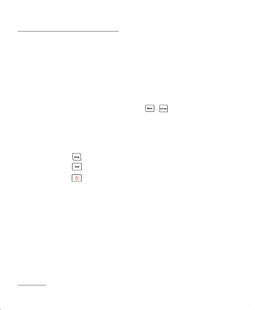
Activating the Backlight
When operating the unit in the dark, use the backlight to make data on the
display more visible. The keypad buttons will also light for about 10
seconds.
Note: When backlight is activated, you must always press a button once to light
the keypad, then press the actual button you want.
To activate/deactivate the backlight:
From normal operating mode, hold down ( on FLS-600) a few
seconds.
Accessing and Navigating Setup Menus
Setup menus differ in each model. You may access and navigate menus as
follows:
Press repeatedly to switch between options in a menu level.
Press once to access a submenu from the main level.
Press to exit menus (one level at a time).
Note: Details about each menu option are given in this user guide.
14 FPM/FLS/FOT-600
Page 21
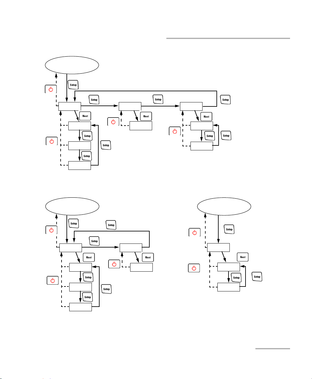
FOT-600
Normal Mode
PM DATA SRC
*
P/F
CAB1
Getting Started
Accessing and Navigating Setup Menus
FAV
FAV
CF
FPM-600
Normal Mode
PM DATA
P/F
FAV
CF
*: Default name
CAB1
*: Default name
PREF
FLS-600
Normal Mode
SRC
*
FAV
PREF
Power Meter/Light Source/Optical Loss Test Set 15
Page 22
Getting Started
Installing the EXFO Universal Interface (EUI)
Installing the EXFO Universal Interface (EUI)
The EUI fixed baseplate is available for connectors with angled (APC) or
non-angled (UPC) polishing. A green border around the baseplate
indicates that it is for APC-type connectors.
Green border
indicates APC
option
Bare metal
(or blue border)
indicates UPC
option
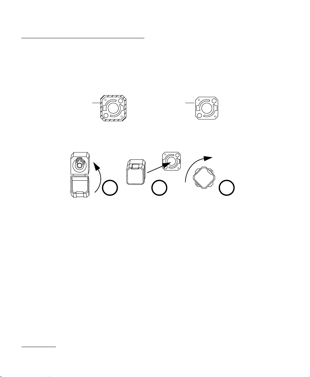
To install an EUI connector adapter onto the EUI baseplate:
1. Hold the EUI connector adapter so the dust cap opens downwards.
2 3 4
2. Close the dust cap in order to hold the connector adapter more firmly.
3. Insert the connector adapter into the baseplate.
4. While pushing firmly, turn the connector adapter clockwise on the
baseplate to lock it in place.
16 FPM/FLS/FOT-600
Page 23

Getting Started
Cleaning and Connecting Optical Fibers
Cleaning and Connecting Optical Fibers
IMPORTANT
To ensure maximum power and to avoid erroneous readings:
Always inspect fiber ends and make sure that they are clean as
explained below before inserting them into the port. EXFO is
not responsible for damage or errors caused by bad fiber
cleaning or handling.
Ensure that your patchcord has appropriate connectors. Joining
mismatched connectors will damage the ferrules.
To connect the fiber-optic cable to the port:
1. Inspect the fiber using a fiber inspection microscope. If the fiber is
clean, proceed to connecting it to the port. If the fiber is dirty, clean it as
explained below.
2. Clean the fiber ends as follows:
2a. Gently wipe the fiber end with a lint-free swab dipped in isopropyl
alcohol.
2b. Use compressed air to dry completely.
2c. Visually inspect the fiber end to ensure its cleanliness.
Power Meter/Light Source/Optical Loss Test Set 17
Page 24

Getting Started
Cleaning and Connecting Optical Fibers
3. Carefully align the connector and port to prevent the fiber end from
touching the outside of the port or rubbing against other surfaces.
If your connector features a key, ensure that it is fully fitted into the
port’s corresponding notch.
4. Push the connector in so that the fiber-optic cable is firmly in place,
thus ensuring adequate contact.
If your connector features a screwsleeve, tighten the connector
enough to firmly maintain the fiber in place. Do not overtighten, as this
will damage the fiber and the port.
Note: If your fiber-optic cable is not properly aligned and/or connected, you will
notice heavy loss and reflection.
EXFO uses good quality connectors in compliance with EIA-455-21A
standards.
To keep connectors clean and in good condition, EXFO strongly
recommends inspecting them with a fiber inspection probe before
connecting them. Failure to do so will result in permanent damage to the
connectors and degradation in measurements.
18 FPM/FLS/FOT-600
Page 25

4 Measuring Power or Loss
(FPM-600 and FOT-600)
Nulling Electrical Offsets
Temperature and humidity variations affect the performance of electronic
circuits and optical detectors. Nulling the electrical offsets eliminates these
effects. Your unit has been designed not to require offset nulling under
normal operation, but you should perform it whenever environmental
conditions change significantly or when measuring very low power values.
IMPORTANT
If light reaches the detector when nulling offsets, LIGH appears on
the display and the nulling is not performed. You will need to press
a key to return to the previous display.
Note: Factory-defined values will be reinstated when you turn off the unit.
To perform an offset nulling:
Hold down a few seconds. The unit
displays NULL while nulling the offsets, then
returns to normal mode.
Note: Keypad is disabled during the operation.
Power Meter/Light Source/Optical Loss Test Set 19
Page 26

Measuring Power or Loss (FPM-600 and FOT-600)
Setting Power Correction Factor
Setting Power Correction Factor
You may apply a correction factor (CF) to measured power to compensate
for inaccuracies or drifts. You should change the CF after performing an
offset nulling.
Power
corrected
Power
measured
CF=
For each favorite wavelength, the CF is set to 1.00 at the factory (even if the
unit indicates “----”), but allowed values range between 0.85 and 1.15.
Note: Some other products express the CF in dB, so the CF would be added to
measured power.
To set a correction factor for one or more wavelengths:
1. From normal operating mode, press
repeatedly until you reach PM.
2. Press to access the first submenu, then
press repeatedly until you reach the CF
menu.
3. Press to switch between available
wavelengths. An asterisk (*) appears beside activated correction
factors. If no correction factor is set for a wavelength, the unit indicates
“----”.
4. Press to activate/deactivate the displayed correction factor. A
“CF” indicator will appear next to measured power in normal mode.
20 FPM/FLS/FOT-600
Page 27

Measuring Power or Loss (FPM-600 and FOT-600)
Setting Power Correction Factor
5. Edit the correction factor as follows:
5a. Hold down a few seconds. The first digit of the CF blinks.
5b. Clear all digits by holding down for a few seconds.
AND/OR
Select a digit to change by holding until it blinks, then
increase its value by pressing (it returns to 0 after 9).
5c. While a digit blinks, hold down for a few seconds to save the
modified value (it remains in memory even when you turn off the
unit) or press to return to the previous value without saving.
6. Press twice to exit setup menus.
Power Meter/Light Source/Optical Loss Test Set 21
Page 28

Measuring Power or Loss (FPM-600 and FOT-600)
Defining a List of Favorite Wavelengths
Defining a List of Favorite Wavelengths
You must put the wavelengths you want to use on a list of favorite
wavelengths (the FAV list). Only wavelengths on this list are available for
measurements. You may enter up to 40 favorite wavelengths.
Specifications are guaranteed for calibrated wavelengths only. For other
wavelengths, the unit will determine values based on the calibrated
wavelengths (3-point interpolation).
To add wavelengths to the FAV list (or to remove them):
Detector
Type
Ge 800, 820, 830, 840, 850, 860, 870, 880,
Calibrated
Wavelengths (nm)
Default Favorite
Wavelengths
a
(nm)
910, 980, 1270, 1280, 1290, 1300,
1310, 1320, 1330, 1340, 1350, 1370,
1390, 1410, 1430, 1450, 1460, 1470,
1480, 1490, 1500, 1510, 1520, 1530,
1540, 1550, 1560, 1570, 1580, 1590,
1600, 1610, 1620, 1630, 1640, 1650.
GeX All the above plus 1060. Same as above
a. To revert to default favorite wavelengths see Reverting Unit to Factory Settings on
page 56.
1. From normal operating mode, press
repeatedly until you reach PM.
2. Press to access the first submenu, then
press repeatedly until you reach the FAV
menu.
3. Press to switch between available wavelengths. An asterisk (*)
appears beside wavelengths already on the list. If no wavelength is set
for a position, the unit indicates “----”. You may also press to
switch between defined wavelengths only.
22 FPM/FLS/FOT-600
Page 29

Measuring Power or Loss (FPM-600 and FOT-600)
Defining a List of Favorite Wavelengths
4. Press to include/exclude the displayed wavelength.
5. Edit the wavelength value as follows:
5a. Hold down a few seconds. The first digit of the wavelength
blinks.
5b. Clear all digits by holding down for a few seconds.
AND/OR
Select a digit to change by holding until it blinks, then
increase its value by pressing (it returns to 0 after 9).
5c. While a digit blinks, hold down for a few seconds to save the
modified value (it remains in memory even when you turn off the
unit) or press to return to the previous value without saving.
6. Press twice to exit setup menus.
Power Meter/Light Source/Optical Loss Test Set 23
Page 30

Measuring Power or Loss (FPM-600 and FOT-600)
Referencing Your Power Meter to a Source
Referencing Your Power Meter to a Source
In reference mode, your unit displays the loss created by the fiber under
test only, since a reference value is subtracted from the measured power.
Note: You must set a reference value separately for each wavelength.
Compatible sources (such as FOT-600 and FLS-600) can transmit a power
value to your power meter, avoiding the need for manual referencing.
IMPORTANT
The value sent is not the source’s actual power. It is a user-defined
value that may not take the optical link’s loss into account.
To receive the reference power value from a compatible source:
1. Connect a compatible source to your power
meter (as shown below, with or without a
fiber under test).
2. Use the source to emit the signal that
contains its power value (see To change the
signal modulation: on page 35).
If reference value or units change, the power meter beeps.
The new reference power is displayed in the top right corner (in
dBm) and current loss reading is automatically switched to dB.
Note: When using this feature, you cannot change the power meter’s wavelength
manually. The power meter behavior is totally determined by the source.
24 FPM/FLS/FOT-600
Page 31

Measuring Power or Loss (FPM-600 and FOT-600)
Referencing Your Power Meter to a Source
To reference the power meter to a source manually:
1. Using the proper adapter, connect a light source (such as FLS-600 or
FOT-600) to the detector port of your power meter.
Reference
test jumper
Bulkhead
connector
Light source
test jumper
Power meter
2. Activate the source at the desired wavelength.
3. Match the source and power meter
wavelengths:
If the source emits an auto-wavelength
signal or is in auto-switching mode (see
Automatically Detecting Wavelength on
page 29 and Using Auto-Switching Mode
on page 35), the power meter automatically matches the source
wavelength.
OR
Press to switch between pre-selected wavelengths (see
Defining a List of Favorite Wavelengths on page 22).
4. Hold down for a few seconds. The
power meter stores the currently detected
power as the new reference power.
AdapterReference
Reference power is displayed in the top
right corner (in dBm) and current loss
reading is automatically switched to dB.
Power Meter/Light Source/Optical Loss Test Set 25
Page 32

Measuring Power or Loss (FPM-600 and FOT-600)
Referencing Your Power Meter to a Source
5. Repeat the procedure for each wavelength you want to reference (if
you use auto-switching mode, the power meter automatically
references wavelengths one at a time).
Note: When using dB units, press to display the current wavelength for a
few seconds. To change this wavelength, press again while it is
displayed.
Note: Once all desired wavelengths have been referenced, do not disconnect the
Reference Test Jumper from the source port.
26 FPM/FLS/FOT-600
Page 33

Measuring Power or Loss (FPM-600 and FOT-600)
Measuring Power or Loss
Measuring Power or Loss
Measuring absolute power or link loss is done the same way, except for the
referencing step.
To perform power or loss measurements:
1. If necessary, perform an offset nulling (see Nulling Electrical Offsets on
page 19).
2. Check and clean your fibers appropriately for optimum performance
(see Cleaning and Connecting Optical Fibers on page 17).
3. For loss measurements, reference your power meter to a light source
(see Referencing Your Power Meter to a Source on page 24), then
deactivate the light source.
4. Using the proper adapter and test jumpers, connect a fiber under test
to a light source (such as FLS-600 or FOT-600) and to the detector port
of your unit.
Note: If you have referenced your power meter to a source, simply connect a fiber
under test to the test jumpers used for referencing.
Test
jumper
Bulkhead
connector
Fiber under test
Light source Power meter
Bulkhead
connector
Adapter
Test
jumper
5. Activate the source at the desired wavelength.
Power Meter/Light Source/Optical Loss Test Set 27
Page 34

Measuring Power or Loss (FPM-600 and FOT-600)
Measuring Power or Loss
6. Match the source and power meter
wavelengths:
If the source emits an auto-wavelength
signal or is in auto-switching mode (see
Automatically Detecting Wavelength on
page 29 and see To receive the
auto-wavelength signal or detect the source's auto-switching
mode: on page 29), the power meter automatically matches the
source wavelength.
OR
Press to switch between pre-selected wavelengths (see
Defining a List of Favorite Wavelengths on page 22).
Modulation detected
Actual power or
loss
of fiber under test
When power or loss is outside power limits
(see Technical Specifications on page 67)
When the unit detects a modulated signal, it beeps and displays the
modulation value and average measured power or loss (see left
illustration above). You may notice a slightly unstable last digit.
7. If necessary, change the displayed units by pressing .
8. Repeat the procedure for other wavelengths.
28 FPM/FLS/FOT-600
Page 35

Measuring Power or Loss (FPM-600 and FOT-600)
Automatically Detecting Wavelength
Automatically Detecting Wavelength
Compatible sources (such as FOT-600 and FLS-600) can transmit their
wavelength value through the fiber, avoiding the need to manually match
the source and power meter wavelengths.
Note: When you receive an auto-wavelength signal or when the source is in
auto-switching mode, you cannot manually change the power meter
wavelength. The power meter behavior is totally determined by the source.
To receive the auto-wavelength signal or detect the source's
auto-switching mode:
1. Connect a compatible source to your power
meter.
2. Activate the source in Auto mode (FOT-600
and FLS-600: see Modulating the Source
Signal on page 34) or in auto-switching
mode.
Your power meter automatically matches the source wavelength. If the
wavelengths differ, it also beeps and returns you to normal operating
mode.
Power Meter/Light Source/Optical Loss Test Set 29
Page 36

Measuring Power or Loss (FPM-600 and FOT-600)
Activating Hold Min/Max Power Mode
Activating Hold Min/Max Power Mode
With the Hold Min/Max mode you can record
extreme values of a varying power signal. You
could use it to test the stability of a light source
over time.
In this mode, the unit displays the minimum or
maximum power value read up to now. It
continuously updates the display if a new min/max is measured.
To activate the Hold Min or Hold Max mode:
Press to switch between Hold Max, Hold Min and regular power
measurement.
To reset the maximum or minimum value:
Hold down for a few seconds. The unit displays “_ _ _ _”.
30 FPM/FLS/FOT-600
Page 37

Measuring Power or Loss (FPM-600 and FOT-600)
Setting Pass/Fail Thresholds
Setting Pass/Fail Thresholds
You can define thresholds to specify acceptable power (dBm) or loss (dB)
values for each wavelength. Thresholds are often supplied by system
manufacturers and depend on the system deployed.
When a threshold is activated, the PASS/FAIL
LED is turned on. If it is green, the threshold
succeeded, if the PASS/FAIL LED is red, the
threshold failed.
To set pass/fail thresholds:
1. From normal operating mode, press
repeatedly until you reach PM.
2. Press to access the first submenu, then
press repeatedly until you reach the P/F
menu.
3. Press to switch between power (dBm)
and loss (dB) values.
4. Press to switch between available wavelengths. An asterisk (*)
appears beside activated thresholds. If no threshold is set for a
wavelength, the unit indicates “----”.
5. Press to activate/deactivate the displayed threshold. The
PASS/FAIL LED will light (green or red) when you return to normal
mode.
Power Meter/Light Source/Optical Loss Test Set 31
Page 38

Measuring Power or Loss (FPM-600 and FOT-600)
Setting Pass/Fail Thresholds
6. Edit the pass/fail threshold as follows:
6a. Hold down for a few seconds. The first digit of the threshold
blinks.
6b. Clear all digits by holding down for a few seconds.
AND/OR
Select a digit to change by holding until it blinks, then
increase its value by pressing (it returns to 0 after 9). After
the last digit, all digits blink: you may add/remove the “–” sign by
pressing .
6c. While a digit blinks, hold down for a few seconds to save the
modified value (it remains in memory even when you turn off the
unit) or press to return to the previous value without saving.
7. Press twice to exit setup menus.
32 FPM/FLS/FOT-600
Page 39

5 Using a Light Source (FLS-600
and FOT-600) or VFL
The FLS-600 may contain up to three sources (one-port models) or up to
four sources (two-port models). The FOT-600 may contain up to three
sources.
Note: The VFL option may also be present on the FPM-600 .
Defining a List of Favorite Wavelengths
You may put the wavelengths you want to use on a list of favorite
wavelengths (the FAV list). Only wavelengths on this list are available for
measurements.
At the factory (or after recalibration), the list contains all source
wavelengths.
Note: The list must always contain at least one wavelength. When you empty the
list, the first source wavelength is automatically added.
To add wavelengths to the FAV list (or to remove them):
1. From normal operating mode, press
repeatedly until you reach SRC.
2. Press to access the first submenu, then
press repeatedly until you reach the FAV
menu.
3. Press to switch between available wavelengths. An asterisk (*)
appears beside wavelengths already on the list.
4. Press to include/exclude the displayed wavelength.
5. Press twice to exit setup menus.
Power Meter/Light Source/Optical Loss Test Set 33
Page 40

Using a Light Source (FLS-600 and FOT-600) or VFL
Activating/Deactivating a Light Source or VFL
Activating/Deactivating a Light Source or VFL
Only one source may be active at a time. When no source is active, the unit
displays OFF.
Source wavelength (and VFL indicator)
and modulation (when active)
FOT-600 FLS-600
To activate a light source (or VFL) and change the wavelength:
Press to activate each available source in turn, including the VFL. The
unit displays the wavelength and modulation.
To deactivate the light source:
Press until you get past the last source.
Active source port
Modulating the Source Signal
When you activate the first source (after turning on the unit), the signal is
always CW (unmodulated). When you switch sources, the modulation
remains the same (VFL remembers its own modulation). Modulation is
indicated in the top left (port #1) or top right (port #2) corner.
Available modulation values are: CW, Auto, auto-switching mode,270 Hz,
1 kHz and 2 kHz (VFL: CW and 1 Hz only).
Note: Auto is a modulated signal detected by compatible units (see Automatically
Detecting Wavelength on page 29). It provides longer battery life than CW,
but covers a reduced power range.
34 FPM/FLS/FOT-600
Page 41

Using a Light Source (FLS-600 and FOT-600) or VFL
Using Auto-Switching Mode
Note: Auto-switching mode is a special signal detected by compatible units (see
Using Auto-Switching Mode on page 35).
To change the signal modulation:
1. Activate the source.
2. Press to switch between available
modulations.
Using Auto-Switching Mode
In auto-switching mode, your source
automatically switches from one wavelength to
another. When connected to the light source, a
compatible power meter displays the power
value for each wavelength one at a time. The
wavelength value appearing on the display
changes every two seconds.
The unit will show the source's favorite wavelengths one at a time (see
Defining a List of Favorite Wavelengths on page 33).
To activate auto-switching mode:
1. Press to activate the source.
2. Press to switch between available modulations until the Auto
indicator blinks on your display.
Power Meter/Light Source/Optical Loss Test Set 35
Page 42

Using a Light Source (FLS-600 and FOT-600) or VFL
Sending Source Power Value with Signal
Sending Source Power Value with Signal
Your source can transmit a user-defined power value to compatible power
meters (such as FOT-600 and FPM-600) through the fiber. If the reference
source is far from the power meter, you can connect your source to the
power meter to send the reference value. With this feature you can also
correct for power variations.
Note: If you connect a fiber between FOT-600’s source and detector ports, the unit
can use the actual source output power as reference power.
Note: For details about how compatible power meters receive this power value,
see Referencing Your Power Meter to a Source on page 24.
IMPORTANT
The value sent is not (and will not affect) the source’s actual power.
It is a user-defined value that may not take the optical link’s loss
into account.
36 FPM/FLS/FOT-600
Page 43

Using a Light Source (FLS-600 and FOT-600) or VFL
Sending Source Power Value with Signal
To define the source power value to use as reference:
1. From normal operating mode, press repeatedly until you reach
SRC.
2. Press to access the first submenu, then press repeatedly
until you reach the PREF menu.
3. Press to switch between available source wavelengths and select
one. The unit displays the currently defined power value for this
wavelength.
4. Edit the power value as follows:
4a. Hold down for a few seconds. The first digit of the power
value blinks.
4b. Revert all digits to 0 by holding down for a few seconds.
AND/OR
Select a digit to change by pressing until it blinks, then
increase its value by pressing (it returns to 0 after 9). After
the last digit, all digits blink: you may add/remove the “–” sign by
pressing .
4c. While a digit blinks, hold down for a few seconds to save the
modified value (it remains in memory even when you turn off the
unit) or press to return to the previous value without saving.
5. Press twice to exit setup menus.
Power Meter/Light Source/Optical Loss Test Set 37
Page 44

Using a Light Source (FLS-600 and FOT-600) or VFL
Sending Source Power Value with Signal
To use the source’s actual output power as reference (FOT-600
only):
1. Connect a fiber between the source and power meter of same unit.
2. Activate the source at the desired wavelength.
3. Match the source and power meter
wavelengths:
If the source emits an auto-wavelength
signal or is in auto-switching mode (see
Automatically Detecting Wavelength on
page 29 and Using Auto-Switching Mode
on page 35), the power meter automatically matches the source
wavelength.
OR
Press to switch between pre-selected wavelengths (see
Defining a List of Favorite Wavelengths on page 22).
4. From normal operating mode, hold down and . The unit
displays PREF for a few seconds while saving the value, then returns to
normal mode.
To send the source power value:
1. Activate the source.
2. Change the modulation signal to AUTO or auto-switching.
If you use auto-switching mode, the power value of each wavelength
will automatically be sent.
38 FPM/FLS/FOT-600
Page 45

6 Saving and Recalling
Power/Loss Values
You can save 1000 power/loss values in your unit, along with references.
You will save and recall this data according to cable names and fiber
numbers. To free up memory, you can transfer saved data to a computer or
simply delete all.
Setting Autonaming Scheme
When saving data, the unit suggests fiber IDs based on autonaming
settings. After saving a value, the unit prepares the next fiber ID according
to the selected increment (0, 1 or 2).
To define the cable name and the starting fiber ID and increment
value:
1. From normal operating mode, press
repeatedly until you reach DATA.
2. Press to access CAB1 or the last cable
name edited.
3. Hold down until the first character of
the cable name blinks.
4. Select a character to change by holding until it blinks, then
increase its value by pressing (it returns to 0 after Z).
5. While a digit blinks, hold down for a few seconds to save the
modified value (it remains in memory even when you turn off the unit)
or press to return to the previous value without saving.
6. Press twice to exit setup menus.
Power Meter/Light Source/Optical Loss Test Set 39
Page 46

Saving and Recalling Power/Loss Values
Saving, Recalling and Deleting Data
Saving, Recalling and Deleting Data
IMPORTANT
You cannot recover deleted data. Ensure that you transfer your
data to a computer if you intend to use it later.
Deleting a single value does not free memory. To free memory,
you must delete all data at once.
To save a power/loss value:
1. If you want to view or change the fiber ID
before saving:
1a. From normal operating mode, press
or to view the fiber ID that
will be used next.
1b. Change the fiber ID by using and to move forward or
backward in the list.
2. Hold down for a few seconds to save the measured value under
the selected fiber ID.
40 FPM/FLS/FOT-600
Page 47

Saving and Recalling Power/Loss Values
Saving, Recalling and Deleting Data
IMPORTANT
When the power meter is connected to the fiber or DUT, you must
wait until at least one loss measurement is displayed on the power
meter before pressing the button.
Once you have pressed the button, you must wait until the Store
indicator on-screen disappears before disconnecting the power
meter or light source to test the next fiber or DUT.
When in Auto-Switching mode, it is important NOT to disconnect
the power meter or light source from the fiber or DUT before the
storage sequence is complete. The storage sequence is complete
when the Store indicator turns off.
The storage process will save the upcoming values, not the
preceding ones.
To recall saved data:
1. From normal operating mode, hold down
for a few seconds. The Recall indicator
is displayed with the cable name, then the
last saved value and its fiber ID.
2. When fiber ID is displayed, hold down
for a few seconds to return to the cable
name list. Select the cable in which you want to recall saved data by
using and to move forward or backward. The last saved
value in the selected cable and its fiber ID will be displayed after 3
seconds.
3. View values you want by using and to move forward or
backward in saved data. You can also change the units by pressing
.
4. Press to return to normal mode.
Power Meter/Light Source/Optical Loss Test Set 41
Page 48

Saving and Recalling Power/Loss Values
Saving, Recalling and Deleting Data
To delete a single saved value from the unit:
1. From normal operating mode, hold down
for a few seconds. The Recall indicator
is displayed with the cable name, then the
last saved value and its fiber ID.
2. When fiber ID is displayed, hold down
a few seconds to return to the cable name
list. Select the cable in which you want to delete saved data by using
and to move forward or backward. The last saved value in
the selected cable and its fiber ID will be displayed after 3 seconds.
3. Select the value to delete by using and to move forward or
backward in saved data.
4. Hold down a few seconds. The unit displays “dEL”, then displays
another saved data.
5. Press to return to normal mode.
To delete a cable name:
1. From normal operating mode, hold down
a few seconds. The Recall indicator is
displayed with the last cable name, then the
last saved value and its fiber ID.
2. When fiber ID is displayed, hold down
for a few seconds to return to the cable
name list, then, select the cable you want to delete by using and
to move forward or backward.
3. Hold down a few seconds. The unit displays “dEL”, then displays
another cable name.
4. Press to return to normal mode.
42 FPM/FLS/FOT-600
Page 49

Saving and Recalling Power/Loss Values
Transferring Data to a Computer
To delete all saved data from the unit:
1. From normal operating mode, hold down
a few seconds.The Recall indicator is
displayed with the last cable name, then the
last saved value and its fiber ID.
2. When fiber ID is displayed, hold down both
and for a few seconds. The unit
displays “dEL” and “ALL”, then automatically returns to normal mode.
Transferring Data to a Computer
Using an appropriate USB cable and the Handheld Data Transfer software,
you can transfer saved data from your handheld unit to a computer. This
way, you can increase storage capacity, perform better analyses on your
data and create reports.
IMPORTANT
Transferred data is not automatically deleted from your unit.
To transfer data to a computer:
1. Using a USB cable, connect your unit to an available USB port of the
computer.
2. Turn on both the computer and your handheld unit. Connect your unit
to a power outlet to ensure that your unit will remain on during the
transfer.
3. On the computer, launch the Handheld Data Transfer application and
start the operation.
The unit displays “REM” and temporarily deactivates the keyboard and
auto-off.
Note: For details about setting up the software and transferring data, refer to the
Handheld Data Transfer online help.
Power Meter/Light Source/Optical Loss Test Set 43
Page 50

Page 51

7 Maintenance
This product contains no user-serviceable parts. However, it contains
sensitive electronic and optical components, and should be handled
carefully and stored in its carrying case when not in use.
To help ensure long, trouble-free operation:
Always inspect fiber-optic connectors before using them and clean
them if necessary.
Keep the unit free of dust.
Clean the unit casing and front panel with a cloth slightly dampened
with water.
Store unit at room temperature in a clean and dry area. Keep the unit
out of direct sunlight.
Avoid high humidity or significant temperature fluctuations.
Avoid unnecessary shocks and vibrations.
If any liquids are spilled on or into the unit, turn off the power
immediately, disconnect from any external power source, remove the
batteries and let the unit dry completely.
The use of controls, adjustments and procedures other than those
specified herein may result in exposure to hazardous situations or
impair the protection provided by this unit.
WARNING
Cleaning EUI Connectors
Regular cleaning of EUI connectors will help maintain optimum
performance. There is no need to disassemble the unit.
IMPORTANT
If any damage occurs to internal connectors, the module casing will
have to be opened and a new calibration will be required.
Power Meter/Light Source/Optical Loss Test Set 45
Page 52

Maintenance
Cleaning EUI Connectors
Looking into the optical connector while the light source is active
WILL result in permanent eye damage. EXFO strongly recommends
to TURN OFF the unit before proceeding with the cleaning
procedure.
To clean EUI connectors:
1. Remove the EUI from the instrument to expose the connector
baseplate and ferrule.
WARNING
Turn
Push
2. Moisten a 2.5 mm cleaning tip with one drop of isopropyl alcohol
(alcohol may leave traces if used abundantly).
3. Slowly insert the cleaning tip into the EUI adapter until it comes out on
the other side (a slow clockwise rotating movement may help).
Pull
3
4
5
4. Gently turn the cleaning tip one full turn, then continue to turn as you
withdraw it.
5. Repeat steps 3 to 4 with a dry cleaning tip.
Note: Make sure you don’t touch the soft end of the cleaning tip.
46 FPM/FLS/FOT-600
Page 53

Maintenance
Cleaning EUI Connectors
6. Clean the ferrule in the connector port as follows:
6a. Deposit one drop of isopropyl alcohol on a lint-free wiping cloth.
IMPORTANT
Isopropyl alcohol may leave residues if used abundantly or left to
evaporate (about 10 seconds).
Avoid contact between the tip of the bottle and the wiping cloth,
and dry the surface quickly.
6b. Gently wipe the connector and ferrule.
6c. With a dry lint-free wiping cloth, gently wipe the same surfaces to
ensure that the connector and ferrule are perfectly dry.
6d. Verify connector surface with a portable fiber-optic microscope
(for example, EXFO’s FOMS) or fiber inspection probe (for
example, EXFO’s FIP).
7. Put the EUI back onto the instrument (push and turn clockwise).
8. Throw out cleaning tips and wiping cloths after one use.
Power Meter/Light Source/Optical Loss Test Set 47
Page 54

Maintenance
Cleaning Fixed Connectors
Cleaning Fixed Connectors
Regular cleaning of connectors will help maintain optimum performance.
Do not try to disassemble the unit. Doing so would break the connector.
Looking into the optical connector while the light source is active
WILL result in permanent eye damage. EXFO strongly recommends
to TURN OFF the unit before proceeding with the cleaning
procedure.
To clean fixed connectors:
1. Fold a lint-free wiping cloth in four to form a square.
2. Moisten the center of the lint-free wiping cloth with only one drop of
isopropyl alcohol.
Alcohol may leave traces if used abundantly. Avoid contact between
the tip of the bottle and the wiping cloth, and do not use bottles
that distribute too much alcohol at a time.
WARNING
IMPORTANT
3. Gently wipe the connector threads three times with the folded and
moistened section of the wiping cloth.
IMPORTANT
Isopropyl alcohol takes approximately ten seconds to evaporate.
Since isopropyl alcohol is not absolutely pure, evaporation will
leave microscopic residue. Make sure you dry the surfaces before
evaporation occurs.
4. With a dry lint-free wiping cloth, gently wipe the same surfaces three
times with a rotating movement.
48 FPM/FLS/FOT-600
Page 55

Maintenance
Cleaning Fixed Connectors
5. Throw out the wiping cloths after one use.
6. Moisten a cleaning tip (2.5 mm tip) with only one drop of isopropyl
alcohol.
IMPORTANT
Alcohol may leave traces if used abundantly. Avoid contact between
the tip of the bottle and the cleaning tip, and do not use bottles
that distribute too much alcohol at a time.
7. Slowly insert the cleaning tip into the connector until it reaches the
ferrule inside (a slow clockwise rotating movement may help).
7
8
9
8. Gently turn the cleaning tip one full turn.
9. Continue to turn as you withdraw the cleaning tip.
10. Repeat steps 7 to 9, but this time with a dry cleaning tip (2.5 mm tip
provided by EXFO).
Note: Make sure you don’t touch the soft end of the cleaning tip and verify the
cleanliness of the cotton tip.
11. Throw out the cleaning tips after one use.
Power Meter/Light Source/Optical Loss Test Set 49
Page 56

Maintenance
Cleaning VFL-Type Connectors
Cleaning VFL-Type Connectors
VFL-type connectors are fixed on your unit and can be cleaned using a
mechanical cleaner.
Verifying the surface of the connector with a fiber-optic microscope
WHILE THE UNIT IS ACTIVE WILL result in permanent eye damage.
WARNING
To clean a connector using a mechanical cleaner:
1. Insert the mechanical into the optical adapter, and push the outer shell
into the cleaner.
Note: The cleaner makes a clicking sound to indicate that the cleaning is done.
2. Verify connector surface with a portable fiber-optic microscope (for
example, EXFO’s FOMS) or fiber inspection probe (for
example, EXFO’s FIP).
50 FPM/FLS/FOT-600
Page 57

Maintenance
Cleaning Detector Ports
Cleaning Detector Ports
Regular cleaning of detectors will help maintain measurement accuracy.
IMPORTANT
Always cover detectors with protective caps when unit is not in use.
To clean detector ports:
1. Remove the protective cap and adapter (FOA) from the detector.
2. If the detector is dusty, blow dry with compressed air.
3. Being careful not to touch the soft end of the swab, moisten a cleaning
tip with only one drop of isopropyl alcohol.
IMPORTANT
Alcohol may leave traces if used abundantly. Do not use bottles that
distribute too much alcohol at a time.
4. While applying light pressure (to avoid breaking the detector window),
gently rotate the cleaning tip on the detector window.
5. Repeat step 4 with a dry cleaning tip or blow dry with compressed air.
6. Discard the cleaning tips after one use.
Power Meter/Light Source/Optical Loss Test Set 51
Page 58

Maintenance
Recharging and Replacing the Battery
Recharging and Replacing the Battery
The Li-Ion battery will last about 70 hours (power meter) or 50 hours
(source in Auto mode) in normal operation. The charge status is shown on
the unit display (lower left corner).
IMPORTANT
The battery is not charged at the factory. Fully charge it (about
4 hours) before using it for the first time.
The battery functions and charges properly between 0 oC and
45 oC (32 oF and 113 oF). It will not charge if the temperature is
below -10 oC (14 oF) or above 45 oC (113 oF).
Never store battery at temperatures above 60 oC (140 oF).
Charge only with specified charger.
Note: Charging your unit’s battery can take up to 5 hours. This battery was
custom-made for your unit; replacement batteries must be purchased from
EXFO.
To recharge the Li-Ion battery:
Connect the unit to a power outlet (or car outlet) using the AC
adapter/charger. The charge cycle will start and end automatically.
Note: While charging, the battery indicator animates continuously. It does not
reflect the actual charge status until charging is complete.
52 FPM/FLS/FOT-600
Page 59

Maintenance
Recharging and Replacing the Battery
To replace the battery:
1. Turn off the unit (if the AC adapter is
plugged in, you may replace the battery
while unit is on).
2. Remove the battery compartment cover,
located at the back of the unit.
3. Pull out the old b battery using your
fingers. Flipping the unit, battery-side
down, will ease removal. Do not use tools
in order to prevent damage to the battery envelope. Pull out the
electrical connector. Put aside the old battery.
4. Remove the new battery from its package (keep the package for future
use). Connect the electrical connector, ensuring that the pins are
correctly aligned. Place the new battery into the unit.
5. Inspect the inside rib around the unit battery compartment to make
sure it is free from any debris. Remove any debris using a dry cloth.
Replace the battery compartment cover.
WARNING
Only use an EXFO battery. Batteries from other suppliers could
result in serious damage to your unit, or personal injuries. See
Contacting the Technical Support Group on page 58 for more
information on contacting EXFO.
WARNING
Do not throw batteries into fire or water and do not short-circuit
the batteries’ electrical contacts. Do not disassemble.
Power Meter/Light Source/Optical Loss Test Set 53
Page 60

Maintenance
Recalibrating the Unit
Recalibrating the Unit
Manufacturing and service center calibrations are based on the
ISO/IEC 17025 Standard, which states that calibration documents must not
contain a recommended calibration interval, unless this has been
previously agreed upon with the customer.
Validity of specifications depends on operating conditions. For example,
the calibration validity period can be longer or shorter depending on the
intensity of use, environmental conditions and unit maintenance. You
should determine the adequate calibration interval for your unit according
to your accuracy requirements.
Under normal use, EXFO recommends calibrating your unit every three
years.
Note: The FlexCare warranty program includes Calibration/Verification packages
(see Service and Repairs on page 64).
To view the last calibration date (FOT-600 and FPM-600 only):
1. From normal operating mode, hold down
and for a few seconds. The unit displays
the first embedded software version.
2. Press until you reach the calibration date
(and version) of the power meter.
3. Press to return to normal mode.
Recycling and Disposal (Applies to European Union Only)
For complete recycling/disposal information as per European Directive
WEEE 2012/19/UE, visit the EXFO Web site at www.exfo.com/recycle.
54 FPM/FLS/FOT-600
Page 61

8 Troubleshooting
Solving Common Problems
Problem Possible Cause Solution
The unit does not turn on. You did not press
long enough.
AC adapter/charger
not connected.
Main battery
discharged.
Weather too cold.
The unit takes very long to
turn on.
Battery does not charge as
expected.
Unable to change power
meter wavelength.
Too many values saved
in memory.
Temperature too
high.
Battery incorrectly
connected.
Incorrect charger
used.
Unit receiving Auto
(or REF) signal
from source.
Only one
wavelength in list.
Press for 2
seconds.
Connect AC
adapter/charger and
charge battery.
Delete all data from
the unit.
Ensure temperature is
within specifications.
Ensure battery is
connected properly.
Use the correct
charger.
Change source mode
(see Modulating the
Source Signal on
page 34), then retry.
Add wavelengths.
Power Meter/Light Source/Optical Loss Test Set 55
Page 62

Troubleshooting
Reverting Unit to Factory Settings
Problem Possible Cause Solution
Unable to change power
meter dB unit or reference
power.
OR
Changed unit or reference
value are replaced by other
values after a while.
Many beeps, unstable optical
power and blinking Auto (or
modulation) indicator.
Reference power different
than source output power.
Unit displays FULL even after
you deleted a few values.
Going from the first value to
the last value in recalled data
is very slow.
Unit receiving REF
signal from source. See
Sending Source Power
Value with Signal on
page 36.
Power too low to
recognize Auto mode
(or modulation).
Received power
outside detector’s
range.
You must delete all
values from the unit to
free memory.
Too many values saved
in memory.
Wait a few seconds
until power value is
received, then retry.
Increase source
power or switch
source to CW.
Change source output
power.
Delete all values as
explained in Saving,
Recalling and
Deleting Data on
page 40.
Delete all data from
the unit.
Reverting Unit to Factory Settings
You can revert most parameters on your unit to their factory state. When
you perform this operation, you will lose all customized parameters.
To revert unit to factory settings:
1. Turn off your unit.
2. While holding down , press . When your unit beeps, release
.
56 FPM/FLS/FOT-600
Page 63

Troubleshooting
Error Codes and Descriptions
Error Codes and Descriptions
ER: error code displayed until you press a key.
WR: warning code displayed for 3 seconds, then unit returns to
normal.
Error
Code
LIGH Light detected while nulling
offsets. Nulling is not
Description Solution
Correctly place protective cap
on detector port, then retry.
performed.
FULL Storage memory full. Delete data.
EMPt Storage memory empty:
You pressed Recall but no
Add data.
data was saved.
Last saved data deleted.
All data deleted.
29/30/
Calibration errors. Contact EXFO.
34/36/
56/57
18/52 Incompatible wavelengths or
power too low in PREF on
FOT-600.
Match source and power
meter wavelengths or increase
source power.
Power Meter/Light Source/Optical Loss Test Set 57
Page 64

Troubleshooting
Contacting the Technical Support Group
Contacting the Technical Support Group
To obtain after-sales service or technical support for this product, contact
EXFO at one of the following numbers. The Technical Support Group is
available to take your calls from Monday to Friday, 8:00 a.m. to 7:00 p.m.
(Eastern Time in North America).
Technical Support Group
400 Godin Avenue
Quebec (Quebec) G1M 2K2
CANADA
For detailed information about technical support, and for a list of other
worldwide locations, visit the EXFO Web site at www.exfo.com.
To accelerate the process, please have information such as the name and
the serial number (see the product identification label), as well as a
description of your problem, close at hand.
You may also be requested to provide the embedded software’s version
numbers.
1 866 683-0155 (USA and Canada)
Tel.: 1 418 683-5498
Fax: 1 418 683-9224
support@exfo.com
To display the embedded software version:
1. From normal operating mode, hold down
and for a few seconds. The unit displays
the first software version.
2. Press to switch between the software and
hardware versions.
Press to return to normal mode.
58 FPM/FLS/FOT-600
Page 65

Troubleshooting
Transportation
Transportation
Maintain a temperature range within specifications when transporting the
unit. Transportation damage can occur from improper handling. The
following steps are recommended to minimize the possibility of damage:
Pack the unit in its original packing material when shipping.
Avoid high humidity or large temperature fluctuations.
Keep the unit out of direct sunlight.
Avoid unnecessary shocks and vibrations.
Power Meter/Light Source/Optical Loss Test Set 59
Page 66

Page 67

9 Warranty
General Information
EXFO Inc. (EXFO) warrants this equipment against defects in material and
workmanship for a period of three years from the date of original
shipment. EXFO also warrants that this equipment will meet applicable
specifications under normal use.
During the warranty period, EXFO will, at its discretion, repair, replace,
or issue credit for any defective product, as well as verify and adjust the
product free of charge should the equipment need to be repaired or if the
original calibration is erroneous. If the equipment is sent back for
verification of calibration during the warranty period and found to meet all
published specifications, EXFO will charge standard calibration fees.
The warranty can become null and void if:
unit has been tampered with, repaired, or worked upon by
unauthorized individuals or non-EXFO personnel.
warranty sticker has been removed.
IMPORTANT
case screws, other than those specified in this guide, have been
removed.
case has been opened, other than as explained in this guide.
unit serial number has been altered, erased, or removed.
unit has been misused, neglected, or damaged by accident.
THIS WARRANTY IS IN LIEU OF ALL OTHER WARRANTIES EXPRESSED,
IMPLIED, OR STATUTORY, INCLUDING, BUT NOT LIMITED TO, THE
IMPLIED WARRANTIES OF MERCHANTABILITY AND FITNESS FOR A
PARTICULAR PURPOSE. IN NO EVENT SHALL EXFO BE LIABLE FOR
SPECIAL, INCIDENTAL, OR CONSEQUENTIAL DAMAGES.
Power Meter/Light Source/Optical Loss Test Set 61
Page 68

Warranty
Liability
Liability
EXFO shall not be liable for damages resulting from the use of the product,
nor shall be responsible for any failure in the performance of other items to
which the product is connected or the operation of any system of which
the product may be a part.
EXFO shall not be liable for damages resulting from improper usage or
unauthorized modification of the product, its accompanying accessories
and software.
62 FPM/FLS/FOT-600
Page 69

Warranty
Exclusions
Exclusions
EXFO reserves the right to make changes in the design or construction of
any of its products at any time without incurring obligation to make any
changes whatsoever on units purchased. Accessories, including but not
limited to fuses, pilot lamps, batteries and universal interfaces (EUI) used
with EXFO products are not covered by this warranty.
This warranty excludes failure resulting from: improper use or installation,
normal wear and tear, accident, abuse, neglect, fire, water, lightning or
other acts of nature, causes external to the product or other factors beyond
the control of EXFO.
IMPORTANT
In the case of products equipped with optical connectors, EXFO will
charge a fee for replacing connectors that were damaged due to
misuse or bad cleaning.
Certification
EXFO certifies that this equipment met its published specifications at the
time of shipment from the factory.
Power Meter/Light Source/Optical Loss Test Set 63
Page 70

Warranty
Service and Repairs
Service and Repairs
EXFO commits to providing product service and repair for five years
following the date of purchase.
To send any equipment for service or repair:
1. Call one of EXFO’s authorized service centers (see EXFO Service
2. If equipment must be returned to EXFO or an authorized service
3. If possible, back up your data before sending the unit for repair.
4. Pack the equipment in its original shipping material. Be sure to include
5. Return the equipment, prepaid, to the address given to you by support
Centers Worldwide on page 65). Support personnel will determine if
the equipment requires service, repair, or calibration.
center, support personnel will issue a Return Merchandise
Authorization (RMA) number and provide an address for return.
a statement or report fully detailing the defect and the conditions under
which it was observed.
personnel. Be sure to write the RMA number on the shipping slip. EXFO
will refuse and return any package that does not bear an RMA number.
Note: A test setup fee will apply to any returned unit that, after test, is found to
meet the applicable specifications.
After repair, the equipment will be returned with a repair report. If the
equipment is not under warranty, you will be invoiced for the cost
appearing on this report. EXFO will pay return-to-customer shipping costs
for equipment under warranty. Shipping insurance is at your expense.
Routine recalibration is not included in any of the warranty plans. Since
calibrations/verifications are not covered by the basic or extended
warranties, you may elect to purchase FlexCare Calibration/Verification
Packages for a definite period of time. Contact an authorized service center
(see EXFO Service Centers Worldwide on page 65).
64 FPM/FLS/FOT-600
Page 71

Warranty
EXFO Service Centers Worldwide
EXFO Service Centers Worldwide
If your product requires servicing, contact your nearest authorized service
center.
EXFO Headquarters Service Center
400 Godin Avenue
Quebec (Quebec) G1M 2K2
CANADA
EXFO Europe Service Center
Winchester House, School Lane
Chandlers Ford, Hampshire S053 4DG
ENGLAND
EXFO Telecom Equipment
(Shenzhen) Ltd.
3rd Floor, Building 10,
Yu Sheng Industrial Park (Gu Shu
Crossing), No. 467,
National Highway 107,
Xixiang, Bao An District,
Shenzhen, China, 518126
1 866 683-0155 (USA and Canada)
Tel.: 1 418 683-5498
Fax: 1 418 683-9224
support@exfo.com
Tel.: +44 2380 246800
Fax: +44 2380 246801
support.europe@exfo.com
Tel: +86 (755) 2955 3100
Fax: +86 (755) 2955 3101
support.asia@exfo.com
Power Meter/Light Source/Optical Loss Test Set 65
Page 72

Page 73

A Technical Specifications
IMPORTANT
The following technical specifications can change without notice.
The information presented in this section is provided as a reference
only. To obtain this product’s most recent technical specifications,
visit the EXFO Web site at www.exfo.com.
FPM-600
SPECIFICATIONSa
Model FPM-602 FPM-602X
Detector Ge GeX
Power range (dBm)b 10 to –70 26 to –55
Wavelength range (nm) 800 to 1650 800 to
1650
Calibrated wavelengths (nm) 800, 820, 830, 840, 850, 860, 870, 880, 910, Same calibrated
980, 1270, 1280, 1290, 1300, 1310, 1320, wavelengths as the
1330, 1340, 1350, 1370, 1390, 1410, 1430, FPM-602, plus 1060
1450, 1460, 1470, 1480, 1490, 1500, 1510,
1520, 1530, 1540, 1550, 1560, 1570, 1580,
1590, 1600, 1610, 1620, 1630, 1640, 1650
Power uncertainty
Resolution (dB) ±0.01 (10 dBm to –60 dBm) ±0.01 (26 dBm to –45 dBm)
Automatic offset nulling
Display units dB, dBm, W dB, dBm, W
Tone detection 270 Hz, 1 kHz and 2 kHz 270 Hz, 1 kHz and 2 kHz
Auto-switching
Warm-up period (min)
Data storage (items) more than 1000 more than 1000
Battery life (hours) (typical) 72 72
Warranty and recommended
recalibration interval (years) 3 3
c
±5 % ± 0.1 nW ±5 % ± 3 nW
d
Yes Yes
e
Yes Yes
f
0 0
GENERAL SPECIFICATIONS
Size (H x W x D) 190 mm x 100 mm x 62 mm (7 1/2 in x 4 in x 2 1/2 in)
Weight 0.48 kg (1.1 lb)
Temperature operating –10 °C to 50 °C (14 °F to 122 °F)
storage –40 °C to 70 °C (–40 °F to 158 °F)
ORDERING INFORMATION
Relative humidity 0 % to 95 % non-condensing
STANDARD ACCESSORIES
User guide, Certificate of Calibration, instrument stickers
in six languages, AC adapter/charger, lithium ion battery,
shoulder strap, carrying case, USB cable.
NOTES
a. Guaranteed unless otherwise specified. All specifications valid
at 1550 nm and 23 °C ± 1 °C, with an FC connector.
b. In CW mode; sensitivity defined as 6 x rms noise level.
c. For calibrated wavelengths. Valid up to 20 dBm for
FPM-602X.
d. For power > –40 dBm for FPM-602, and > –25 dBm
for FPM-602X.
e. At 850 nm, 1300 nm, 1310 nm, 1490 nm, 1550 nm
and 1650 nm; for power > –50 dBm for FPM-602 and
> –40 dBm (typical) for FPM-602X.
f. For a variation of ) 0.06 dB at power levels * –40 dBm
for FPM-602 and * –25 dBm for FPM-602X.
Power Meter/Light Source/Optical Loss Test Set 67
Page 74

Technical Specifications
SPECIFICATIONS
a
Model 12D 23BL 234BL 235BL
Central wavelength (nm) 850 ± 25
1300 +50/–10
1310 ± 20
1550 ± 20
1310 ± 20
1550 ± 20
1625 ± 15
1310 ± 20
1490 ± 10
1550 ± 20
Spectral width
b
(nm) 50/135 )5 )5 )5
Output power (dBm) *–20/*–20 (62.5/125 μm) *1/*1 *1/*–3/*–5 *1/*–4.5/*–3
Power stability
c
(dB)
15 min
8 h
±0.05
±0.1
±0.03
±0.1
±0.03
±0.1
±0.03
±0.1
Auto-switching Yes Yes Yes Yes
Tone generation 270 Hz, 1 kHz, 2 kHz 270 Hz, 1 kHz, 2 kHz 270 Hz, 1 kHz, 2 kHz 270 Hz, 1 kHz, 2 kHz
Battery life (hours) (typical in Auto mode) 50 50 50 50
Warranty (years) 3 3 3 3
GENERAL SPECIFICATIONS
a
Size (H x W x D) 190 mm x 100 mm x 62 mm (7 1/2 in x 4 in x 2 1/2 in)
Weight 0.48 kg (1.1 lb)
Temperature
operating
storage
—10 °C to 50 °C
—40 °C to 70 °C
(14 °F to 122 °F)
(—40 °F to 158 °F)
Relative humidity 0 % to 95 % non-condensing
FLS-600
FLS-600
68 FPM/FLS/FOT-600
Page 75

FOT-600
SPECIFICATIONS
a
Model FOT-602X
Detector GeX
Power range (dBm)
b
26 to −55
Wavelength range (nm) 800 to 1650
Calibrated wavelengths (nm) 800, 820, 830, 840, 850, 860, 870, 880, 910, 980, 1270, 1280, 1290, 1300, 1310, 1320, 1330, 1340,
1350, 1370, 1390, 1410, 1430, 1450, 1460, 1470, 1480, 1490, 1500, 1510, 1520, 1530, 1540, 1550,
1560, 1570, 1580, 1590, 1600, 1610, 1620, 1630, 1640, 1650, 1060
Power uncertainty
c
±5 % ± 3 nW
Resolution (dB) ±0.01 (26 dBm to −45 dBm)
Automatic offset nulling
d
Yes
Display units dB, dBm, W
Tone detection 270 Hz, 1 kHz and 2 kHz
Auto-switching
e
Yes
Warm-up period (min)
f
0
Data storage (items) More than 1000
Battery life (hours) (typical) 72
Warranty and recommended calibration period (years) 3
Model 23BL
Central wavelength (nm) 1310 ± 20
1550 ± 20
Spectral width (nm)
g
)5
Output power (dBm) *1
Power stability (dB)
h
15 min
8 h
±0.03
±0.1
Tone generation 270 Hz, 1 kHz, 2 kHz
Automatic wavelength recognition Yes
Battery life (hours) (typical in Auto mode) 50
Warranty and recommended calibration period (years) 3
Technical Specifications
FOT-600
NOTES
a. Guaranteed unless otherwise specified. All specifications valid at 23 °C ± 1 °C, with an FC
b. In CW mode; sensitivity defined as 6 x rms noise level.
c. For calibration wavelengths. Valid up to 20 dBm for FOT-602X.
d. For power > −25 dBm for FOT-602X.
e. At 850 nm, 1300 nm, 1310 nm, 1490 nm, 1550 nm and 1625 nm; for power > −40 dBm (typical)
f. For a variation of ) 0.06 dB at power levels * −25 dBm for FOT-602X.
g. rms for FP lasers.
Power Meter/Light Source/Optical Loss Test Set 69
connector and at 1550 nm for detector.
for FOT-602X.
h. After a 15-minute warm-up period, and using an APC connector on the power meter (except for
i. Typical values in 62.5/125 μm fiber.
multimode sources, for which a PC connector is used). Expressed as ± half the difference between
the maximum and minimum values measured during the period.
Page 76

Page 77

NOTICE
抩⛙
CHINESE REGULATION ON RESTRICTION OF HAZARDOUS SUBSTANCES
₼⦌␂ℝ☀⹂䓸德棟Ⓟ䤓屓⸩
NAMES AND CONTENTS OF THE TOXIC OR HAZARDOUS SUBSTANCES OR ELEMENTS
▔⚺⦷㦻 EXFO ℶ❐₼䤓㦘㹡㦘⹂䓸德㒥⏒侯䤓⚜䱿✛⚺摞
Indicates that this toxic or hazardous substance contained in all of the homogeneous
materials for this part is below the limit requirement in SJ/T11363-2006
O
嫷䯉年㦘㹡㦘⹂䓸德⦷年捷ↅ㓏㦘⧖德㧟㠨₼䤓⚺摞⧖⦷ SJ/T11363-2006 㪖屓⸩䤓
棟摞尐㻑ⅴₚᇭ
Indicates that this toxic or hazardous substance contained in at least one of the homogeneous
materials used for this part is above the limit requirement in SJ/T11363-2006
X
嫷䯉年㦘㹡㦘⹂䓸德咂⺠⦷年捷ↅ䤓㩟⧖德㧟㠨₼䤓⚺摞怔⒉ SJ/T11363-2006 㪖
屓⸩䤓棟摞尐㻑ᇭ
Part Na me
捷ↅ⚜䱿
Lead
(Pb)
Enclosure
⮥⮂
Electronic and
electrical
sub-assembly
䟄✛䟄兓ↅ
Optical
sub-assembly
⏘ⷵ兓ↅ
Mechanical
sub-assembly
㧉㬿兓ↅ
a. If applicable.
Ⱁ㨫抑䞷ᇭ
a
a
a
a
CONTAINED IN THIS EXFO PRODUCT
Toxic or hazardous Substances and Elements
㦘㹡㦘⹂䓸德✛⏒侯
杔
Mercury
㻭
(Hg)
Cadmium
椣
(Cd)
Hexavalent
Chromium
⏼ↆ杻
(Cr VI)
Poly br om ina te d
biphenyls
⮩䅃勣啾
(PBB)
Polybrominated
diphenyl ethers
⮩䅃ℛ啾搩
(PBDE)
OO O O O O
XO X O X X
XO O O O O
OO O O O O
Page 78

MARKING REQUIREMENTS
㪖㽷尐㻑
Product
ℶ❐
This Exfo product
㦻 EXFO ℶ❐
Battery
䟄㻯
a. If applicable.
Ⱁ㨫抑䞷ᇭ
Environmental protection use period (years)
䘾⬒≬㔳∎䞷㦮棟 ( )
Logo
㪖㉦
10
a
a
5
Page 79

P/N: 1064230
www.EXFO.com · info@exfo.com
CORPORATE HEADQUARTERS 400 Godin Avenue Quebec (Quebec) G1M 2K2 CANADA
Tel.: 1 418 683-0211 · Fax: 1 418 683-2170
EXFO AMERICA 3400 Waterview Parkway Suite 100 Richardson, TX 75080 USA
EXFO EUROPE Winchester House,
EXFO ASIA-PACIFIC 100 Beach Road,
EXFO CHINA Beijing Global Trade Center, Tower C,
EXFO SERVICE ASSURANCE 270 Billerica Road Chelmsford MA, 01824 USA
EXFO FINLAND Elektroniikkatie 2 FI-90590 Oulu, FINLAND
TOLL-FREE (USA and Canada) 1 800 663-3936
© 2013 EXFO Inc. All rights reserved.
Printed in Canada (2013-03)
School Lane
#25-01/03 Shaw Tower
Room 1207, 36 North Third Ring Road
East, Dongcheng District
Tel.: 1 972-761-927 · Fax: 1 972-761-9067
Chandlers Ford, Hampshire S053 4DG ENGLAND
Tel.: +44 2380 246 800 · Fax: +44 2380 246 801
SINGAPORE 189702
Tel.: +65 6333 8241 · Fax: +65 6333 8242
Beijing 100013 P. R. CHINA
Tel.: +86 (10) 5825 7755 · Fax: +86 (10) 5825 7722
Tel.: 1 978 367-5600 · Fax: 1 978 367-5700
Tel.: +358 (0) 403 010 300 · Fax: +358 (0) 8 564 5203
 Loading...