

Page 1
FOT-5200
CWDM Analyzer
User Guide
Page 2

Copyright © 2010–2011 EXFO Inc. All rights reserved. No part of this
publication may be reproduced, stored in a retrieval system or transmitted
in any form, be it electronically, mechanically, or by any other means such
as photocopying, recording or otherwise, without the prior written
permission of EXFO Inc. (EXFO).
Information provided by EXFO is believed to be accurate and reliable.
However, no responsibility is assumed by EXFO for its use nor for any
infringements of patents or other rights of third parties that may result from
its use. No license is granted by implication or otherwise under any patent
rights of EXFO.
EXFO’s Commerce And Government Entities (CAGE) code under the North
Atlantic Treaty Organization (NATO) is 0L8C3.
The information contained in this publication is subject to change without
notice.
Trademarks
EXFO’s trademarks have been identified as such. However, the presence
or absence of such identification does not affect the legal status of any
trademark.
Units of Measurement
Units of measurement in this publication conform to SI standards and
practices.
Version number: 2.0.0
ii FOT-5200
Page 3

Contents
Contents
Certification Information ........................................................................................................v
1 Introducing the FOT-5200 CWDM Analyzer ................................................. 1
Main Functions .......................................................................................................................3
Conventions ............................................................................................................................4
2 Safety Information ....................................................................................... 5
Battery Charger .......................................................................................................................6
3 Setting Up and Operating your FOT-5200 ................................................... 9
Cleaning and Connecting Optical Fibers .................................................................................9
Turning Unit On and Off .......................................................................................................10
Menu Tree .............................................................................................................................11
User Specification (CWDM SCAN) .........................................................................................16
Scanning All Channels (ALL SCAN) ........................................................................................18
Finding Relative Value (dB) of All Channels ...........................................................................19
General Power Meter ............................................................................................................20
dB/dBm .................................................................................................................................21
Graph Data Display ...............................................................................................................22
Saving Information and Naming Files ...................................................................................23
Opening Files ........................................................................................................................24
4 Maintenance ............................................................................................... 25
Cleaning Detector Ports ........................................................................................................26
Recalibrating the Unit ...........................................................................................................27
Recycling and Disposal (Applies to European Union Only) ....................................................27
5 Troubleshooting ......................................................................................... 29
Solving Common Problems ...................................................................................................29
Contacting the Technical Support Group ..............................................................................29
Viewing System Information .................................................................................................30
Transportation ......................................................................................................................30
CWDM Analyzer iii
Page 4

Contents
6 Warranty ......................................................................................................31
General Information .............................................................................................................31
Liability .................................................................................................................................32
Exclusions .............................................................................................................................33
Certification ..........................................................................................................................33
Service and Repairs ...............................................................................................................34
EXFO Service Centers Worldwide ..........................................................................................35
A Technical Specifications ..............................................................................37
iv FOT-5200
Page 5

Certification Information
Certification Information
Federal Communications Commission (FCC) and
Industry Canada Information
Electronic test and measurement equipment is exempt from FCC part 15,
subpart B compliance in the United States of America and from ICES-003
compliance in Canada. However, EXFO Inc. makes reasonable efforts to
ensure compliance to the applicable standards.
The limits set by these standards are designed to provide reasonable
protection against harmful interference when the equipment is operated in
a commercial environment. This equipment generates, uses, and can
radiate radio frequency energy and, if not installed and used in accordance
with the user guide, may cause harmful interference to radio
communications. Operation of this equipment in a residential area is likely
to cause harmful interference in which case the user will be required to
correct the interference at his own expense.
Modifications not expressly approved by the manufacturer could void the
user's authority to operate the equipment.
Information
Electronic test equipment is subject to the EMC Directive in the European
Union. The IEC 61326-1 standard prescribes both emission and immunity
requirements for laboratory, measurement, and control equipment.
This unit has undergone extensive testing according to the European Union
Directive and Standards.
CWDM Analyzer v
Page 6

Certification Information
DECLARATION OF CONFORMITY
Application of Council Directive(s):
2006/95/EC – The Low Voltage Directive
2004/108/EC – The EMC Directive
93/68/EEC – CE Marking
And their amendments
Manufacturer’s Name and Address:
EXFO Inc. EXFO Europe
400 Godin Avenue Omega Enterprise Park, Electron Way
Quebec City, Quebec Chandlers Ford, Hampshire
G1M 2K2 CANADA SO53 4SE ENGLAND
Tel.: +1 418 683-0211 Tel.: +44 2380 246810
Equipment Type/Environment:
Test & Measurement / Industrial
Trade Name/Model No.:
CWDM ANALYZER / FOT-5200
Standard(s) to which Conformity is declared:
EN 61010-1:2001 Edition 2.0
Safety requirements for electrical equipment for measurement,
control, and
laboratory use – Part 1: General requirements
EN 61326-1:2006
Electrical equipment for measurement, control and laborator y use –
EMC requirements
– Part 1: General requirements
EN 60825-1:2007 Edition 2.0
Safety of laser products – Part 1: Equipment classification and
requirements
I, the undersigned, hereby declare that the equipment specified above conforms to the above Directive and Standards.
Manufacturer:
Stephen Bull, E. Eng
Vice-President Research and Development
400 Godin Avenue,
Quebec City, Quebec
G1M 2K2 CANADA
August 18, 2010
vi FOT-5200
Page 7

1 Introducing the FOT-5200
CWDM Analyzer
The FOT-5200 CWDM Analyzer is designed to measure and mark
wavelengths in order to measure the exact power independently for each
coarse wavelength division multilplexing (CWDM) channel. This
instrument is portable and made to be appropriate to the outside
environment.
When using a broadband powermeter, only the total optical power of the
combined CWDM channels can be measured. When several wavelengths
are sent at once, the exact value of each wavelength cannot be measured.
Thus for CWDM, which functions over several wavelengths, a device that
can distinguish the wavelengths must be used.
The FOT-5200 is developed to measure exact power and is adaptable to
the various network conditions. It is especially suitable for outer
environments and is compact, therefore easy to carry.
CWDM Analyzer 1
Page 8
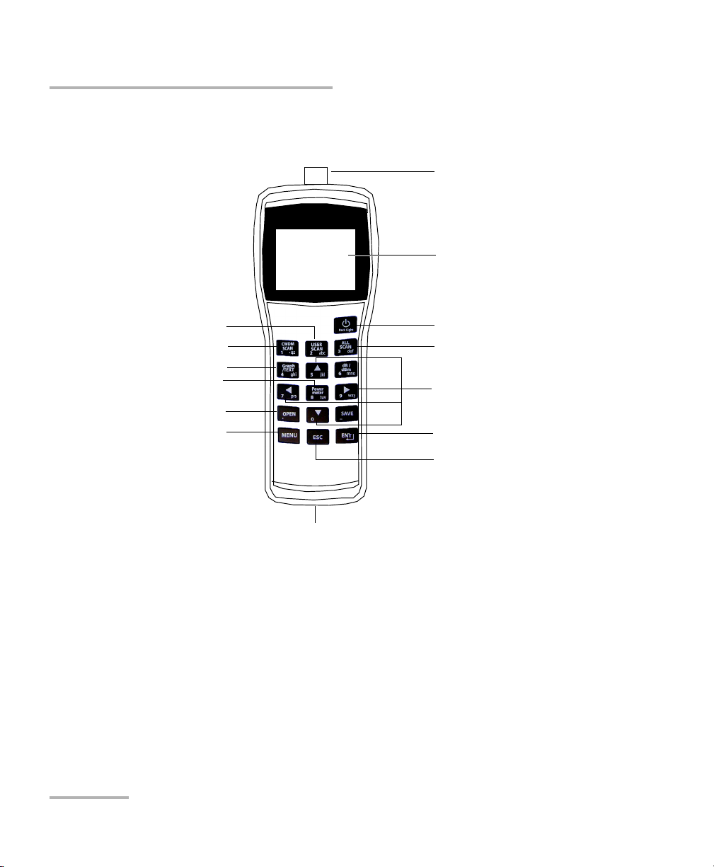
Introducing the FOT-5200 CWDM Analyzer
Display
Optical port
Power key
Escape key
Enter key
Arrow keys
Charging and data
communication port
Open file key
Menu key
All scan key
User scan key
View mode key
Power meter key
CWDM scan key
The picture below shows the FOT-5200, and the usage of the keypad
essential in operating the measuring instrument.
2 FOT-5200
Page 9
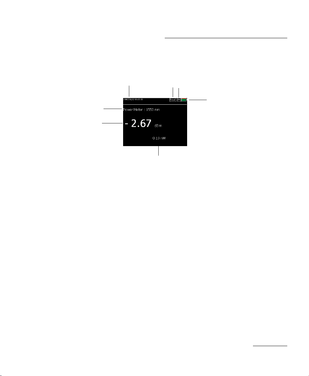
Introducing the FOT-5200 CWDM Analyzer
Date and time
Channel mode
Current
channel power
Current
measurement
mode
Power unit
Battery level
Optical module detection status
(shows X if not detected)
Main Functions
The picture below shows the display screen when measuring a single
channel.
Main Functions
Simultaneous measurement of optical power in all channels in a single
scan, which is the key factor in the field of installation, maintenance
and repair.
CWDM Analyzer 3
Works as a broadband power meter and as a loss meter.
It is compact in size and lightweight for excellent portability.
Can use the existing charger and USB Data Communication Cable by
using a typical cell phone 24-pin connector
Fea tures a co lor LCD
Sorts measured data
Saves/Reads measured data
Displays measured time
Page 10

Introducing the FOT-5200 CWDM Analyzer
Conventions
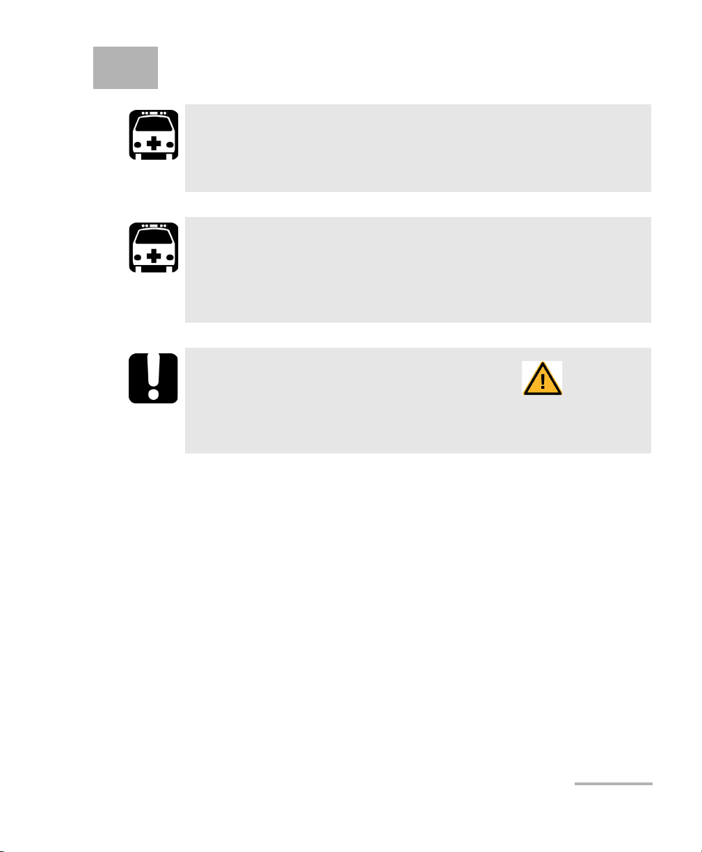
Conventions
Before using the product described in this guide, you should understand
the following conventions:
WARNING
Indicates a potentially hazardous situation which, if not avoided,
could result in death or serious injury. Do not proceed unless you
understand and meet the required conditions.
CAUTION
Indicates a potentially hazardous situation which, if not avoided,
may result in minor or moderate injury. Do not proceed unless you
understand and meet the required conditions.
CAUTION
Indicates a potentially hazardous situation which, if not avoided,
may result in component damage. Do not proceed unless you
understand and meet the required conditions.
IMPORTANT
Refers to information about this product you should not overlook.
4 FOT-5200
Page 11
2 Safety Information
WARNING
Do not install or terminate fibers while a light source is active.
Never look directly into a live fiber and ensure that your eyes are
protected at all times.
WARNING
Use of controls, adjustments and procedures for operation and
maintenance other than those specified herein may result in
hazardous radiation exposure or impair the protection provided by
this unit.
IMPORTANT
When you see the following symbol on your unit , make sure
that you refer to the instructions provided in your user
documentation. Ensure that you understand and meet the required
conditions before using your product.
To prevent fire or injury:
Use an appropriate battery. Use only a battery approved for the
product.
Connect and disconnect the battery properly.
Do not disconnect the battery when the product is on.
Check the patchcord standard. Use the appropriate type of connector
for the product to prevent damage of connector or error of measured
value by checking whether the adaptor type is right for the connector
at time of purchase.
Follow all connector standards. To avoid damage or shock of product,
follow all instructions for connectors and product. Refer to the product
manual before connecting the product and check additional
information on adaptor.
CWDM Analyzer 5
Page 12
Safety Information
Battery Charger
Turn off the product’s power using the Power button.
Do not operate the product with the cover removed.
Do not operate a product suspected of being damaged. Have it
checked by a certified professional technician.
Do not touch exposed circuits. Do not touch exposed connections or
parts when power is being supplied.
Do not use in damp environments.
Keep the surface of product clean and dry.
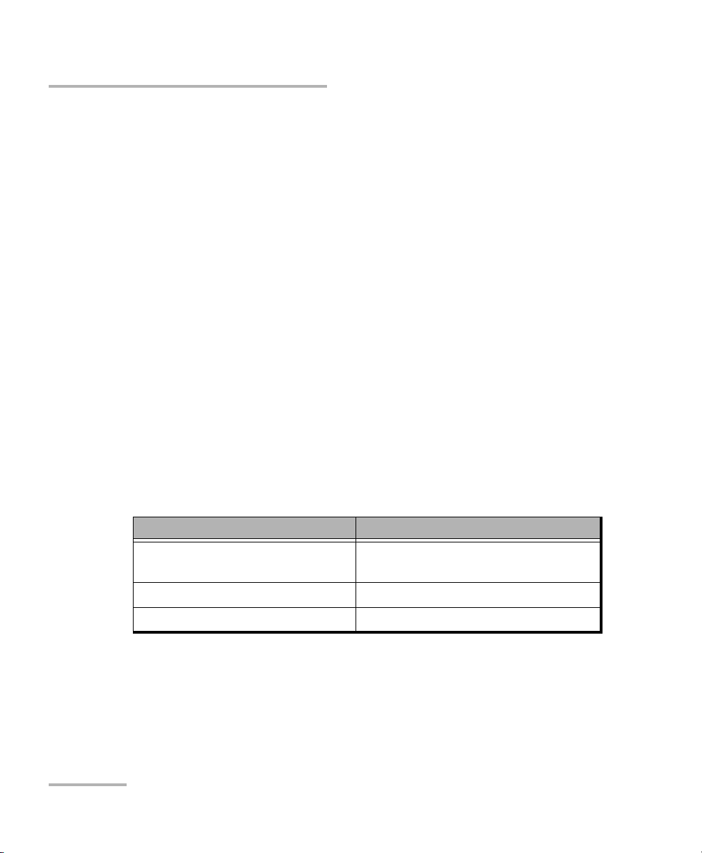
Battery Charger
A rechargeable battery is installed inside the measuring instrument, and
this charger module has a standard 24-pin charger port.
When the charger module is connected to the measuring instrument, the
circular picture on the connecting part points to the bottom of the
instrument.
The LED on the charger module indicates different situations depending on
its color and state:
Color Status
Red, ON (continuous) The charger module is in charging
mode.
Green, ON (continuous) Charge complete. Ready to use.
Red, Blinking Error or damage to battery.
6 FOT-5200
Page 13

Safety Information
Battery Charger
Here are additional precautions pertaining to battery use:
Charging time is about five hours. If the indicating lamp has changed
add one more hour.
Do not allow battery to short circuit.
Keep the battery away from fire. There is danger of explosion when the
battery is near fire.
Never dismantle, change structure or distort the battery. See on
page 27 for more information.
Do not dip the battery in water or other liquids.
Do not store the battery in places warmer than 40 degrees Celsius.
Do not drop or give a shock to the battery.
Ensure the battery is oriented correctly.
Power of charger is 110~220V at 50/60 Hz.
Remove the battery when it is not in use for a long time.
CWDM Analyzer 7
Page 14

Page 15

3 Setting Up and Operating
your FOT-5200
Cleaning and Connecting Optical Fibers
IMPORTANT
To ensure maximum power and to avoid erroneous readings:
Always inspect fiber ends and make sure that they are clean as
explained below before inserting them into the port. EXFO is
not responsible for damage or errors caused by bad fiber
cleaning or handling.
Ensure that your patchcord has appropriate connectors. Joining
mismatched connectors will damage the ferrules.
To connect the fiber-optic cable to the port:
1. Inspect the fiber using a fiber inspection microscope. If the fiber is
clean, proceed to connecting it to the port. If the fiber is dirty, clean it as
explained below.
2. Clean the fiber ends as follows:
2a. Gently wipe the fiber end with a lint-free swab dipped in isopropyl
alcohol.
2b. Use compressed air to dry completely.
2c. Visually inspect the fiber end to ensure its cleanliness.
CWDM Analyzer 9
Page 16

Setting Up and Operating your FOT-5200
Turning Unit On and Off
3. Carefully align the connector and port to prevent the fiber end from
touching the outside of the port or rubbing against other surfaces.
If your connector features a key, ensure that it is fully fitted into the
port’s corresponding notch.
4. Push the connector in so that the fiber-optic cable is firmly in place,
thus ensuring adequate contact.
If your connector features a screwsleeve, tighten the connector
enough to firmly maintain the fiber in place. Do not overtighten, as this
will damage the fiber and the port.
Note: If your fiber-optic cable is not properly aligned and/or connected, you will
notice heavy loss and reflection.
Turning Unit On and Off
The Power button ( ) is used to turn the unit on and off.
If you press Power for more than 1.5
seconds, the logo appears and the unit
beeps. It then moves to Total Power,
which is the basic channel.
Press Power for more than two seconds
to turn the power off.
To adjust LCD Back Light:
It is possible to adjust the brightness of
LCD's back light to one of two levels by
pressing Power for just a short time.
10 FOT-5200
Page 17

Setting Up and Operating your FOT-5200
Menu Tree
If you press MENU ( ), it changes
to a screen where you can configure the
operating environment of FOT-5200 and
set up calibration, special operations,
etc.
The menu includes the features below:
Item Description
USER SCAN User defined channels
OFFSET (VOLATILE) Offset function
USB, RS232 C BAUDRATE Establishes communication
speed
Menu Tree
AUTO POWER OFF Setup for auto-off feature
KEY LIGHT OFF Manages lighting of keypad
FILE SYSTEM Functions for file
management
SET TIME To set time and date.
SYSINFO Information on equipment
CALIBRATION EXFO use only.
Note: Malfunction of the FOT-5200 can occur due to incorrect setup of functions.
CWDM Analyzer 11
Page 18

Setting Up and Operating your FOT-5200
Menu Tree
User-Defined Channels (USER SCAN)
USER SCAN ( ) is a button assigned to scan only channels defined by
the user.
To set up USER SCAN:
1. Press MENU to change to the menu screen.
2. Use the arrow buttons to select
USER SCAN, then press ENT.
As the channel values that users
mainly use are provided in the
above screen, it is easy to set up the
channel value that you want.
3. If you press ENT after selecting
USER SELECT, you can select the
channel that you want. If you then
press ENT, it changes from OFF to ON.
The set up value is automatically saved
if you come out using the ESC key after
finishing channel selection.
Note: The measurement time depends on the
number of channels selected. Choosing
the correct channels to be measured
minimizes measurement time.
Mobile telecommunication companies
use 1310, 1550 nm for 2 G optic wavelengths and 1510, 1530, 1570 nm for
3 G optic wavelengths. Thus you should set up the user channel to (1310,
1510, 1530, 1550, 1570) in the menu.
12 FOT-5200
Page 19

Setting Up and Operating your FOT-5200
User Channel Text Mode
User Channel Graph Mode
Menu Tree
When you press Graph/TEXT ( ) after performing a scan with the
USER SCAN button, you can see a user scan graph screen such as the
following.
OFFSET (VOLATILE)
The OFFSET function displays the
addition of set up dBm value and the
optic power value on the screen.
The user can increase reliability and
continuously maintain the measuring
instrument's own features and settings
by synchronizing the output value with
other measuring instruments using the
calibration function for each channel.
Note: As this value is saved in the volatile memory, it becomes zero after booting
and is not remembered if you turn the power off after set up.
CWDM Analyzer 13
Page 20

Setting Up and Operating your FOT-5200
Menu Tree
Communication Speed Set Up (USB, RS-232C,
Baudrate)
If you press the arrow keys in USB
RS232C Baudrate, you can set up the
transmission speed of the COM Port, and
the default value is 115200 bps.
Power management Set Up (Auto Power)
The power automatically goes off if the
user does not press a key in the
determined time.
You can activate or de-activate the
option by pressing ENT and set the time
in minutes using the arrow keys.
LED Management Set Up
(KEYPAD LIGHT OFF)
This is a function to set up power
management of the FOT-5200 like Auto
Pow er.
The lighting goes off if the user does not
press a key during the determined time.
You can activate and de-activate the
option by pressing ENT, and set up the
time in seconds by using the arrow keys.
14 FOT-5200
Page 21

Setting Up and Operating your FOT-5200
File System Set Up (File System)
This provides a function to delete the
files saved in the FOT-5200 and format
transportable memory.
The following shows the screen when
you select FILE SYSTEM in the menu,
then press ENT.
DELETE FILE
If you press ENT key after choosing
the file you want to delete, it is
deleted from the memory.
Menu Tree
Memory FORMAT
You can delete all saved files by
formatting the transportable
memory. Once you have selected
FORMAT, confirm your choice.
IMPORTANT
Formatted memory and deleted data cannot be recovered.
CWDM Analyzer 15
Page 22

Setting Up and Operating your FOT-5200
User Specification (CWDM SCAN)
Set Time (Set Time)
This sets up the date and time on the
FOT-5200, and is not deleted even after
the power goes off.
You change the value by pressing ENT
after moving the selecting window using
the arrow buttons.
It is automatically saved if you press
ESC.
User Specification (CWDM SCAN)
If you press the CWDM SCAN button
( ), the display mode changes to
One Channel text view like the Power
meter button ( ).
The only difference is that you
personally have to choose the
wavelength. Thus it asks you which
wavelength as in the following screens.
If you choose one from 1 to 16 and press
ENT, it shows you the corresponding channel.
16 FOT-5200
Page 23

Setting Up and Operating your FOT-5200
To use the feature:
1. Press CWDM SCAN in display mode.
2. When you are asked for a channel
selection, input the channel you
want and press ENT.
3. Enter the channel you want using
the number keys where the cursor
blinks and press ENT.
User Specification (CWDM SCAN)
CWDM Analyzer 17
Page 24

Setting Up and Operating your FOT-5200
Scan all (Text Mode)
Scan all (Graph Mode)
Scan all (Full View)
Scan all (Enlarged View)
Scanning All Channels (ALL SCAN)
Scanning All Channels (ALL SCAN)
The button scans all channels and shows a screen like the following.
If you press Graph/TEXT ( ) after scanning, a graph screen like the one
on the right shows. If you press the button again it returns to text mode.
When in text mode, if you can use the right and left arrow buttons to switch
between the different text display types.
Once in the enlarged view, you can use the up and down arrows to switch
between channels 1 to 8, and 9 to 16. The dB/dBm button ( )
switches between the loss and power values.
18 FOT-5200
Page 25

Setting Up and Operating your FOT-5200
Relative value (dB)
Standard value (dBm)
Relative value (dB)
New absolute value (dBm)
Existing absolute value (dBm)
Finding Relative Value (dB) of All Channels
Finding Relative Value (dB) of All Channels
The following shows the relative value (dB) of all channels based on
independent standard value (dBm), which appears when you press
dB/dBm ( ) on the SCAN ALL screen.
If you press ALL SCAN from the current state, it scans the newly measured
value (dBm) to compare with the existing standard value REF (dBm) and
generates the relative value (dB).
Press dB/dBm once more to cancel the relative value (dB/dBm) mode.
CWDM Analyzer 19
Page 26

Setting Up and Operating your FOT-5200
General Power Meter
General Power Meter
This shows the Power Meter in the basic set up screen without special
manipulation when you turn on FOT-5200's power.
Pressing Power meter ( ) changes the display mode into one-channel
text view. One channel text view is good for observing one channel with a
better visibility of the measurement. It also continuously scans the current
channel.
If you press Power Meter in any area
except the menu set up screen, it
changes to Power Meter which is the
basic channel.
You can change the scan channel by
pressing the Up or Down arrow buttons
in the one channel text view mode.
If you keep pressing the Up arrow
button from the above screen it keeps
changing from 1260 nm to 1620 nm.
If you keep pressing the Down arrow button, it keeps changing from
1620 nm to 1260 nm.
20 FOT-5200
Page 27

Setting Up and Operating your FOT-5200
dB/dBm
The CWDM Analyzer automatically changes to the absolute power value
(dBm or mW) display mode when the power goes on.
The latest scan value is saved as reference value when you press
dB/dBm ( ).
If you press scan after connecting the connector to the optical port that
you want to measure, the standard value and relative value of the current
value are displayed.
Example of using dB/dBm:
1. Select the wavelength for measurement using CWDN SCAN button or
the arrow buttons.
2. Connect the optical source connector which will be saved as the first
reference value to the optic adaptor of FOT-5200.
3. To set up the first reference
value (dBm) as relative value (dB),
press dB/dBm and ensure it displays
0 dB.
dB/dBm
4. After removing the optical source
connector from the FOT-5200,
connect the actual light source to
the FOT-5200 to get the loss value
and check the loss value as shown
to the right.
CWDM Analyzer 21
Page 28

Setting Up and Operating your FOT-5200
Graph Data Display
Graph Data Display
If you press the button, a bar graph is displayed for each channel
value in an easy to read format.
You can use this feature in CWDM SCAN, USER SCAN and SCAN ALL, and
the following shows how it is displayed.
In the case of pressing Graph/Text in CWDM SCAN mode.
In the case of pressing Graph/Text in user-defined channel mode.
In the case of pressing Graph/Text in scanning all channels.
22 FOT-5200
Page 29

Setting Up and Operating your FOT-5200
Saving Information and Naming Files
Saving Information and Naming Files
Saving Files (Save)
This saves the currently displayed value, and you can save all text and
graph modes using the SAVE button ( ).
In the display mode the reference values and the absolute power values of
the 16 scanned channels are saved as a relative value (dB) and the file
extension is .CSA.
When you press SAVE, you must enter a
name for the file to be saved; the file
based on the current date and time is
saved if you press ENT.
You can choose to enter numbers,
small letters or capital letters by moving
the selecting box using the MENU
button when you want to type in the file
name.
CWDM Analyzer 23
Page 30

Setting Up and Operating your FOT-5200
Opening Files
The key acts as a backspace button.
If you want to exit without saving, press the ESC key until all of the file
name letters have been deleted. Press once more on the ESC key. Press
ENT when you are done.
IMPORTANT
If you try to save the file using a name and that it already exists,
you will be notified and the file is not saved.
Note: You can save up to 100 files.
Opening Files
Press OPEN ( )to access the menu
that calls the measured result of optic
power for each channel in the form of
text and graphs. Press OPEN again to
select the file you want and press ENT,
the file is displayed.
Note: If the opened file is in graph mode you
can use the Graph/TEXT button to
change to text mode.
24 FOT-5200
Page 31

4 Maintenance
To help ensure long, trouble-free operation:
Always inspect fiber-optic connectors before using them and clean
them if necessary.
Keep the unit free of dust.
Clean the unit casing and front panel with a cloth slightly dampened
with water.
Store unit at room temperature in a clean and dry area. Keep the unit
out of direct sunlight.
Avoid high humidity or significant temperature fluctuations.
Avoid unnecessary shocks and vibrations.
If any liquids are spilled on or into the unit, turn off the power
immediately, disconnect from any external power source, remove the
batteries and let the unit dry completely.
Use of controls, adjustments, and procedures for operation and
maintenance other than those specified herein may result in
hazardous radiation exposure.
WARNING
CWDM Analyzer 25
Page 32

Maintenance
Cleaning Detector Ports
Use a dustproof cap when not operating to protect from scratches and
contamination.
Plug and connector need to be pulled out carefully as the connector
surface is sensitive.
Remove the battery when not using the unit for a long time.
To prevent damage of equipment surface, do not use abrasives or
chemical cleaners.
Use lens paper and cleaner to clean the sensor surface clockwise.
Cleaning Detector Ports
Regular cleaning of detectors will help maintain measurement accuracy.
CAUTION
CAUTION
To clean detector ports:
1. If the detector is dusty, blow dry with compressed air.
2. Being careful not to touch the soft end of the swab, moisten a cleaning
tip with only one drop of isopropyl alcohol.
IMPORTANT
Alcohol may leave traces if used abundantly. Do not use bottles that
distribute too much alcohol at a time.
3. While applying light pressure, gently rotate the cleaning tip on the
detector window.
4. Repeat step 3 with a dry cleaning tip or blow dry with compressed air.
5. Discard the cleaning tips after one use.
26 FOT-5200
Page 33

Maintenance
Recalibrating the Unit
Recalibrating the Unit
Manufacturing and service center calibrations are based on the
ISO/IEC 17025 Standard, which states that calibration documents must not
contain a recommended calibration interval, unless this has been
previously agreed upon with the customer.
Validity of specifications depends on operating conditions. For example,
the calibration validity period can be longer or shorter depending on the
intensity of use, environmental conditions and unit maintenance. You
should determine the adequate calibration interval for your unit according
to your accuracy requirements.
Under normal use, EXFO recommends calibrating your unit every year.
Recycling and Disposal (Applies to European Union Only)
For complete recycling/disposal information as per European Directive
WEEE 2002/96/EC, visit the EXFO Web site at www.exfo.com/recycle.
CWDM Analyzer 27
Page 34

Page 35

5 Troubleshooting
Solving Common Problems
Here are some common situations, their possible cause and solutions.
Problem Possible Cause Solution
Inferior sensitivity of LCD Battery drained Change and recharge
battery.
No display when pressing the
power button
Battery drained
Wrong battery format
Change and recharge
battery
Contacting the Technical Support Group
To obtain after-sales service or technical support for this product, contact
EXFO at one of the following numbers. The Technical Support Group is
available to take your calls from Monday to Friday, 8:00 a.m. to 7:00 p.m.
(Eastern Time in North America).
For detailed information about technical support, visit the EXFO Web site at
www.exfo.com.
Technical Support Group
400 Godin Avenue
Quebec (Quebec) G1M 2K2
CANADA
To accelerate the process, please have information such as the name and
the serial number (see the product identification label), as well as a
description of your problem, close at hand.
1 866 683-0155 (USA and Canada)
Tel.: 1 418 683-5498
Fax: 1 418 683-9224
support@exfo.com
CWDM Analyzer 29
Page 36

Troubleshooting
Viewing System Information
Viewing System Information
You can view information about your unit
such as the serial number or calibration date
in the SYSINFO window.
To view the information:
Press MENU, then use the arrow keys to
select SYSINFO.
Transportation
Maintain a temperature range within specifications when transporting the
unit. Transportation damage can occur from improper handling. The
following steps are recommended to minimize the possibility of damage:
Pack the unit in its original packing material when shipping.
Avoid high humidity or large temperature fluctuations.
Keep the unit out of direct sunlight.
Avoid unnecessary shocks and vibrations.
30 FOT-5200
Page 37

6 Warranty
General Information
EXFO Inc. (EXFO) warrants this equipment against defects in material and
workmanship for a period of one year from the date of original shipment.
EXFO also warrants that this equipment will meet applicable specifications
under normal use.
During the warranty period, EXFO will, at its discretion, repair, replace,
or issue credit for any defective product, as well as verify and adjust the
product free of charge should the equipment need to be repaired or if the
original calibration is erroneous. If the equipment is sent back for
verification of calibration during the warranty period and found to meet all
published specifications, EXFO will charge standard calibration fees.
The warranty can become null and void if:
unit has been tampered with, repaired, or worked upon by
unauthorized individuals or non-EXFO personnel.
warranty sticker has been removed.
IMPORTANT
case screws, other than those specified in this guide, have been
removed.
case has been opened, other than as explained in this guide.
unit serial number has been altered, erased, or removed.
unit has been misused, neglected, or damaged by accident.
THIS WARRANTY IS IN LIEU OF ALL OTHER WARRANTIES EXPRESSED,
IMPLIED, OR STATUTORY, INCLUDING, BUT NOT LIMITED TO, THE
IMPLIED WARRANTIES OF MERCHANTABILITY AND FITNESS FOR A
PARTICULAR PURPOSE. IN NO EVENT SHALL EXFO BE LIABLE FOR
SPECIAL, INCIDENTAL, OR CONSEQUENTIAL DAMAGES.
CWDM Analyzer 31
Page 38

Warranty
Liability
Liability
EXFO shall not be liable for damages resulting from the use of the product,
nor shall be responsible for any failure in the performance of other items to
which the product is connected or the operation of any system of which
the product may be a part.
EXFO shall not be liable for damages resulting from improper usage or
unauthorized modification of the product, its accompanying accessories
and software.
32 FOT-5200
Page 39

Warranty
Exclusions
EXFO reserves the right to make changes in the design or construction of
any of its products at any time without incurring obligation to make any
changes whatsoever on units purchased. Accessories, including but not
limited to fuses, pilot lamps, batteries and universal interfaces (EUI) used
with EXFO products are not covered by this warranty.
This warranty excludes failure resulting from: improper use or installation,
normal wear and tear, accident, abuse, neglect, fire, water, lightning or
other acts of nature, causes external to the product or other factors beyond
the control of EXFO.
IMPORTANT
EXFO will charge a fee for replacing optical connectors that were
damaged due to misuse or bad cleaning.
Certification
Exclusions
EXFO certifies that this equipment met its published specifications at the
time of shipment from the factory.
CWDM Analyzer 33
Page 40

Warranty
Service and Repairs
Service and Repairs
EXFO commits to providing product service and repair for five years
following the date of purchase.
To send any equipment for service or repair:
1. Call one of EXFO’s authorized service centers (see EXFO Service
2. If equipment must be returned to EXFO or an authorized service
3. If possible, back up your data before sending the unit for repair.
4. Pack the equipment in its original shipping material. Be sure to include
5. Return the equipment, prepaid, to the address given to you by support
Centers Worldwide on page 35). Support personnel will determine if
the equipment requires service, repair, or calibration.
center, support personnel will issue a Return Merchandise
Authorization (RMA) number and provide an address for return.
a statement or report fully detailing the defect and the conditions under
which it was observed.
personnel. Be sure to write the RMA number on the shipping slip. EXFO
will refuse and return any package that does not bear an RMA number.
Note: A test setup fee will apply to any returned unit that, after test, is found to
meet the applicable specifications.
After repair, the equipment will be returned with a repair report. If the
equipment is not under warranty, you will be invoiced for the cost
appearing on this report. EXFO will pay return-to-customer shipping costs
for equipment under warranty. Shipping insurance is at your expense.
Routine recalibration is not included in any of the warranty plans. Since
calibrations/verifications are not covered by the basic or extended
warranties, you may elect to purchase FlexCare Calibration/Verification
Packages for a definite period of time. Contact an authorized service center
(see EXFO Service Centers Worldwide on page 35).
34 FOT-5200
Page 41

Warranty
EXFO Service Centers Worldwide
EXFO Service Centers Worldwide
If your product requires servicing, contact your nearest authorized service
center.
EXFO Headquarters Service Center
400 Godin Avenue
Quebec (Quebec) G1M 2K2
CANADA
EXFO Europe Service Center
Omega Enterprise Park, Electron Way
Chandlers Ford, Hampshire S053 4SE
ENGLAND
EXFO Telecom Equipment
(Shenzhen) Ltd.
3rd Floor, Building 10,
Yu Sheng Industrial Park (Gu Shu
Crossing), No. 467,
National Highway 107,
Xixiang, Bao An District,
Shenzhen, China, 518126
1 866 683-0155 (USA and Canada)
Tel.: 1 418 683-5498
Fax: 1 418 683-9224
support@exfo.com
Tel.: +44 2380 246810
Fax: +44 2380 246801
support.europe@exfo.com
Tel: +86 (755) 2955 3100
Fax: +86 (755) 2955 3101
support.asia@exfo.com
CWDM Analyzer 35
Page 42

Page 43

A Technical Specifications
IMPORTANT
The following technical specifications can change without notice.
The information presented in this section is provided as a reference
only. To obtain this product’s most recent technical specifications,
visit the EXFO Web site at www.exfo.com.
CWDM Analyzer 37
Page 44

Page 45

NOTICE
抩⛙
CHINESE REGULATION ON RESTRICTION OF HAZARDOUS SUBSTANCES
₼⦌␂ℝ☀⹂䓸德棟Ⓟ䤓屓⸩
NAMES AND CONTENTS OF THE TOXIC OR HAZARDOUS SUBSTANCES OR ELEMENTS
CONTAINED IN THIS EXFO PRODUCT
▔⚺⦷㦻 EXFO ℶ❐₼䤓㦘㹡㦘⹂䓸德㒥⏒侯䤓⚜䱿✛⚺摞
O
Indicates that this toxic or hazardous substance contained in all of the homogeneous
materials for this part is below the limit requirement in SJ/T11363-2006
嫷䯉年㦘㹡㦘⹂䓸德⦷年捷ↅ㓏㦘⧖德㧟㠨₼䤓⚺摞⧖⦷ SJ/T11363-2006 㪖屓⸩䤓
棟摞尐㻑ⅴₚᇭ
X
Indicates that this toxic or hazardous substance contained in at least one of the homogeneous
materials used for this part is above the limit requirement in SJ/T11363-2006
嫷䯉年㦘㹡㦘⹂䓸德咂⺠⦷年捷ↅ䤓㩟⧖德㧟㠨₼䤓⚺摞怔⒉ SJ/T11363-2006 㪖
屓⸩䤓棟摞尐㻑ᇭ
Part Name
捷ↅ⚜䱿
Toxic or hazardous Substances and Elements
㦘㹡㦘⹂䓸德✛⏒侯
Lead
杔
(Pb)
Mercury
㻭
(Hg)
Cadmium
椣
(Cd)
Hexavalent
Chromium
⏼ↆ杻
(Cr VI)
Pol yb ro mi na te d
biphenyls
⮩䅃勣啾
(PBB)
Polybrominated
diphenyl ethers
⮩䅃ℛ啾搩
(PBDE)
Enclosure
⮥⮂
OO O O O O
Electronic and
electrical
sub-assembly
䟄✛䟄兓ↅ
XO X O X X
Optical
sub-assembly
a
⏘ⷵ兓ↅ
a
a. If applicable.
Ⱁ㨫抑䞷ᇭ
XO O O O O
Mechanical
sub-assembly
a
㧉㬿兓ↅ
a
OO O O O O
Page 46

MARKING REQUIREMENTS
㪖㽷尐㻑
Product
ℶ❐
Environmental protection use period (years)
䘾⬒≬㔳∎䞷㦮棟 ( )
Logo
㪖㉦
This Exfo product
㦻 EXFO ℶ❐
10
Battery
a
䟄㻯
a
a. If applicable.
Ⱁ㨫抑䞷ᇭ
5
Page 47

P/N: 1062382
www.EXFO.com · info@exfo.com
CORPORATE HEADQUARTERS 400 Godin Avenue Quebec (Quebec) G1M 2K2 CANADA
Tel.: 1 418 683-0211 · Fax: 1 418 683-2170
EXFO AMERICA 3400 Waterview Parkway Suite 100 Richardson, TX 75080 USA
EXFO EUROPE Omega Enterprise Park,
EXFO ASIA-PACIFIC 100 Beach Road,
EXFO CHINA Beijing Global Trade Center, Tower C,
EXFO SERVICE ASSURANCE 270 Billerica Road Chelmsford MA, 01824 USA
EXFO NETHAWK Elektroniikkatie 2 FI-90590 Oulu, FINLAND
TOLL-FREE (USA and Canada) 1 800 663-3936
© 2011 EXFO Inc. All rights reserved.
Printed in Canada (2011-12)
Electron Way
#22-01/03 Shaw Tower
Room 1207, 36 North Third Ring Road
East, Dongcheng District
Tel.: 1 972-761-927 · Fax: 1 972-761-9067
Chandlers Ford, Hampshire S053 4SE ENGLAND
Tel.: +44 2380 246810 · Fax: +44 2380 246801
SINGAPORE 189702
Tel.: +6563338241 · Fax: +6563338242
Beijing 100013 P. R. CHINA
Tel.: +86 (10) 5825 7755 · Fax: +86 (10) 5825 7722
Tel.: 1 978 367-5600 · Fax: 1 978 367-5700
Tel.: +358 (0) 403 010 300 · Fax: +358 (0) 8 564 5203
 Loading...