

Page 1

CD/PMD ANALYZER SOURCE
R&D AND MANUFACTURING
FLS-5834A
USER GUIDE
Page 2

Copyright © 2003–2007 EXFO Electro-Optical Engineering Inc. All rights
reserved. No part of this publication may be reproduced, stored in a
retrieval system or transmitted in any form, be it electronically,
mechanically, or by any other means such as photocopying, recording or
otherwise, without the prior written permission of EXFO Electro-Optical
Engineering Inc. (EXFO).
Information provided by EXFO is believed to be accurate and reliable.
However, no responsibility is assumed by EXFO for its use nor for any
infringements of patents or other rights of third parties that may result from
its use. No license is granted by implication or otherwise under any patent
rights of EXFO.
EXFO’s Commerce And Government Entities (CAGE) code under the North
Atlantic Treaty Organization (NATO) is 0L8C3.
The information contained in this publication is subject to change without
notice.
Trademarks
EXFO’s trademarks have been identified as such. However, the presence
or absence of such identification does not affect the legal status of any
trademark.
Units of Measurement
Units of measurement in this publication conform to SI standards and
practices.
Patents
EXFO’s Universal Interface is protected by US patent 6,612,750.
Version number 2.0.0.
ii FLS-5834A
Page 3

Contents
Contents
Certification Information ........................................................................................................v
1 Introducing the FLS-5834A CD/PMD Analyzer Source ................................ 1
Front Panel .............................................................................................................................1
Back Panel ..............................................................................................................................2
FLS-5834A Compatibility ........................................................................................................2
Conventions ............................................................................................................................3
2 Safety Information ....................................................................................... 5
LED Safety Information ...........................................................................................................5
Electrical Safety Information ...................................................................................................6
3 Getting Started with Your Light Source ..................................................... 9
Turning On and Off the CD/PMD Analyzer Source ...................................................................9
FLS-5834A CD/PMD Analyzer Source Display ........................................................................10
4 Setting CD/PMD Analyzer Source Parameters .......................................... 11
Setting the Refresh Rate .......................................................................................................12
Setting the Backlight ............................................................................................................13
Setting the Contrast .............................................................................................................13
Setting the Video Mode ........................................................................................................14
Resetting the CD/PMD Analyzer Source ................................................................................15
5 Operating the CD/PMD Analyzer Source ................................................... 17
Cleaning and Connecting Optical Fibers ...............................................................................17
Installing the EXFO Universal Interface (EUI) .........................................................................18
Activating or Deactivating the Source ...................................................................................19
6 Controlling the Source Remotely .............................................................. 21
Setting the Remote Command Mode ...................................................................................23
Setting the GPIB Address ......................................................................................................24
Setting the Baud Rate ...........................................................................................................25
Setting the Flow Control .......................................................................................................26
Communication Parameters ..................................................................................................27
Standard Status Data Structure ............................................................................................28
Command Structure .............................................................................................................33
Error Messages Format .........................................................................................................34
CD/PMD Analyzer Source iii
Page 4

Contents
7 Maintenance ................................................................................................35
Cleaning EUI Connectors ......................................................................................................36
Replacing Fuses ....................................................................................................................38
Recalibrating the Unit ...........................................................................................................39
Upgrading the Embedded Software .....................................................................................40
Recycling and Disposal (Applies to European Union Only) ....................................................42
8 Troubleshooting ..........................................................................................43
CD/PMD Analyzer Source Error Messages .............................................................................43
GPIB Troubleshooting ...........................................................................................................47
Finding Information on the EXFO Web Site ..........................................................................48
Contacting the Technical Support Group ..............................................................................49
Transportation ......................................................................................................................50
9 Warranty ......................................................................................................51
General Information .............................................................................................................51
Liability .................................................................................................................................52
Exclusions .............................................................................................................................52
Certification ..........................................................................................................................52
Service and Repairs ...............................................................................................................53
EXFO Service Centers Worldwide ..........................................................................................54
A Technical Specifications ..............................................................................55
B Rackmount Installation ..............................................................................57
C Remote Control Commands .......................................................................59
IEEE 488.2 Commands—Quick Reference .............................................................................59
IEEE 488.2 Commands—Description ....................................................................................60
Product-Specific Commands—Quick Reference ....................................................................81
Product-Specific Commands-Description ..............................................................................82
D SCPI-Based Errors ........................................................................................85
Index .................................................................................................................87
iv FLS-5834A
Page 5

Certification Information
Certification Information
F.C.C. Information
Electronic test equipment is exempt from Part 15 compliance (FCC) in
the United States. However, compliance verification tests are
systematically performed on most EXFO equipment.
Information
Electronic test equipment is subject to the EMC Directive in the European
Union. The EN61326 standard prescribes both emission and immunity
requirements for laboratory, measurement, and control equipment.
This unit has undergone extensive testing according to the European Union
Directive and Standards.
CSA Information
This unit is certified by the CSA (certificate number 162451) and was
evaluated according to applicable CSA and UL standards (as confirmed by
“C-US” mark) as well as applicable IEC standards for use in Canada, the
United States, and other countries.
CD/PMD Analyzer Source v
Page 6

Certification Information
DECLARATION OF CONFORMITY
Application of Council Directive(s): 73/23/EEC - The Low Voltage Directive
Manufacturer’s Name: EXFO ELECTRO-OPTICAL ENG.
Manufacturer’s Address: 400 Godin Avenue
Equipment Type/Environment: Light Industrial Scientific Equipment
Trade Name/Model No.: FLS-5800 Modulated Broadband Light Source
Standard(s) to which Conformity is Declared:
EN 61010-1:2001 Safety Requirements for Electrical Equipment for Measurement, Control,
EN 60825-1:1994 / A2: 2001 Safety of laser products – Part 1: Equipment classifications, requirements,
EN 61326:1997/ A3: 2003 Electrical Equipment for Measurement, Control and Laboratory
EN 55022: 1998/ A2: 2003 Limits and Methods of Measurement of Radio Disturbance Characteristics
I, the undersigned, hereby declare that the equipment specified above conforms to the above Directive and Standards.
Manufacturer
Signature:
and Laboratory Use, Part 1: General Requirements.
and user’s guide
Use - EMC Requirements
of Information Technology Equipment.
89/336/EEC - The EMC Directive
Quebec, Quebec
Canada G1M 2K2
(418) 683-0211
Full Name: Stephen Bull, E. Eng
Position: Vice-President Research and
Address: 400 Godin Avenue Quebec, Quebec,
Date: February 25, 2002
Development
Canada
vi FLS-5834A
Page 7
1 Introducing the FLS-5834A
CD/PMD Analyzer Source
The FLS-5834A CD/PMD Analyzer Source is a modulated, polarized
broadband fiber-optic source that has been especially designed to be used
with EXFO FTB-5800 Chromatic Dispersion Analyzer.
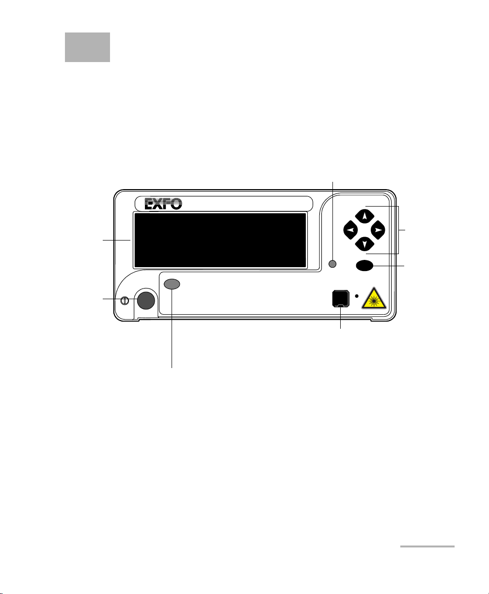
Front Panel
Setup menu access
Display
Turn
unit
ON/OFF
FLS-5834A
On/Off
Source activation/deactivation
button
CD/PMD ANALYZER SOURCE
Setup
Out
Active
Output port
ENTER
Navigation
keys
Confirmation
key
CD/PMD Analyzer Source 1
Page 8
Introducing the FLS-5834A CD/PMD Analyzer Source
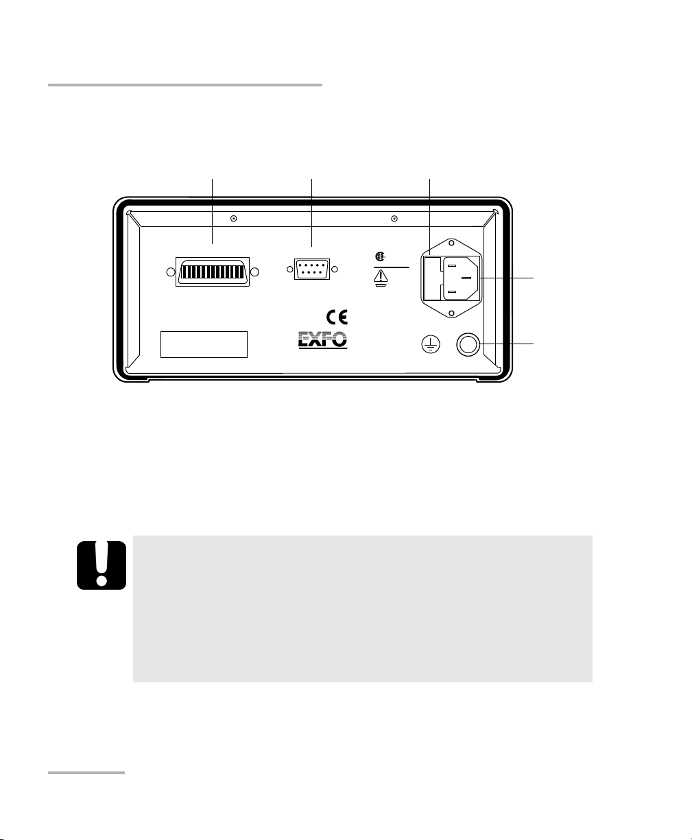
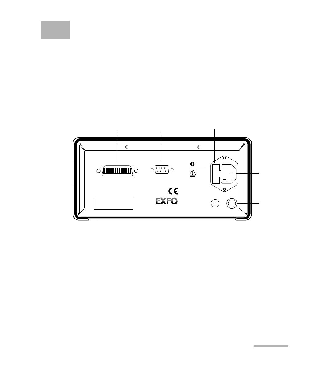
Back Panel
Back Panel
GPIB port
GPIB IEEE 488.2
SH1, AH1, T6, L4, SR1, RL1, PP0, DC1, DT1, C0, E2
This device complies with part 15 of the FCC rules. Operation is
subject to the following two conditions : (1) this device may not cause
harmful interference and (2) this device m ust accept any interference
received, including interference that may cause undesired operation.
P/N
S/N
Made in Canada
Serial port (RS-232 DTE) Fuse holder
CUS
MODEL: GO
LR107723
R
100-240 V
50/60 Hz
2 A
F2AL250 V
QST-151
Serial Port
Ver.
Mfg.
date
Electro-Optical Engineering
FLS-5834A Compatibility
The FLS-5834A is compatible with :
³ FTB-5500B PMD Analyzer
³ FTB-5800 Chromatic Dispersion Analyzer
IMPORTANT
Before using the FLS-5834A with the FTB-5800, you must install:
Power
inlet
Ground
³ ToolBox 6.28 or later.
³ The appropriate product pack (if applicable)
If you are using ToolBox 6.28, ensure to install ToolBox FTB-5800
6.28.1.17 Product Pack.
2 FLS-5834A
Page 9

Introducing the FLS-5834A CD/PMD Analyzer Source
Conventions
Conventions
Before using the product described in this manual, you should understand
the following conventions:
WARNING
Indicates a potentially hazardous situation which, if not avoided,
could result in death or serious injury. Do not proceed unless you
understand and meet the required conditions.
CAUTION
Indicates a potentially hazardous situation which, if not avoided,
may result in minor or moderate injury. Do not proceed unless you
understand and meet the required conditions.
CAUTION
Indicates a potentially hazardous situation which, if not avoided,
may result in component damage. Do not proceed unless you
understand and meet the required conditions.
IMPORTANT
Refers to information about this product you should not overlook.
CD/PMD Analyzer Source 3
Page 10

Page 11

2 Safety Information
WARNING
Do not install or terminate fibers while a light source is active.
Never look directly into a live fiber and ensure that your eyes are
protected at all times.
WARNING
Use of controls, adjustments and procedures for operation and
maintenance other than those specified herein may result in
hazardous radiation exposure.
LED Safety Information
Your instrument is a Class 1M LED product in compliance with standard
IEC 60825-1 Amendment 2: 2001. Invisible LED radiation may be
encountered at the output port.
The product is safe under reasonably foreseeable conditions of operation
but it may be hazardous if you use optics within a diverging or collimated
beam. Do not view directly with optical instruments.
³ Wavelength: 1520 to 1640 nm
³ Maximum output power at the connector: 10 mW
The unit has an active LED on its front panel. When lit, this LED indicates
that an optical signal is being emitted from the source port.
The active LED will turn on three seconds before the source starts emitting.
CD/PMD Analyzer Source 5
Page 12

Safety Information
Electrical Safety Information
Electrical Safety Information
This unit uses an international safety standard three-wire power cable. This
cable serves as a ground when connected to an appropriate AC power
outlet.
Note: If you need to ensure that the unit is completely powered off, disconnect the
power cable.
WARNING
³ Insert the power cable plug into a power outlet with a
protective ground contact. Do not use an extension cord
without a protective conductor.
³ Before powering on the unit, connect all grounding terminals,
extension cords and devices to a protective ground via a ground
socket. Any interruption of the protective grounding is a
potential shock hazard and may cause personal injury.
Whenever the ground protection is impaired, do not use the
unit and secure it against any accidental operation.
³ Do not tamper with the protective ground terminal.
The color coding used in the electric cable depends on the cable. New
plugs should meet the local safety requirements and include:
³ adequate load-carrying capacity
³ ground connection
³ cable clamp
IMPORTANT
EXFO assumes no liability if you attempt to perform internal service
on this unit.
6 FLS-5834A
Page 13

Safety Information
Electrical Safety Information
WARNING
³ Use this unit indoors only.
³ Position the unit so that the air can circulate freely around it.
³ Operation of any electrical instrument around flammable gases
or fumes constitutes a major safety hazard.
³ Do not remove unit covers during operation.
³ To avoid electrical shock, do not operate the unit if any part of
the outer surface (covers, panels, etc.) is damaged.
³ Only authorized personnel should carry out adjustments,
maintenance or repair of opened units under voltage. A person
qualified in first aid must also be present. Do not replace any
components while power cable are connected.
³ Use only fuses with the required rated current and specified
type (IEC, 5 mm x 20 mm (0.197 in x 0.787 in), fast-blow, 250 V,
2 A). Do not use repaired fuses or short-circuited fuse holders.
³ Capacitors inside the unit may be charged even if the unit has
been disconnected from its electrical supply.
CD/PMD Analyzer Source 7
Page 14
Safety Information
Electrical Safety Information
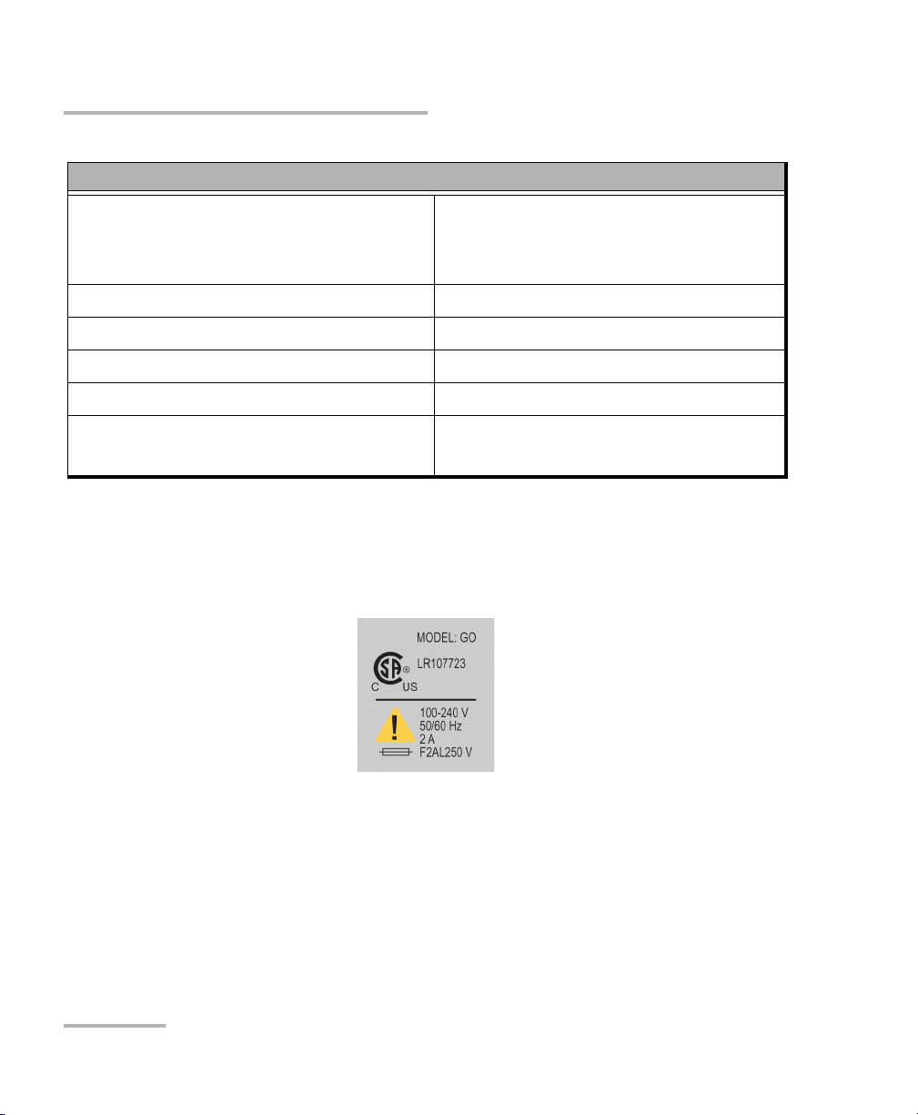
Equipment Ratings
Tem pe ra tu re
³ Operation
³ Storage
Relative humidity
a
0 °C to 40 °C (32 °F to 104 °F)
-40 °C to 70 °C (-40 °F to 158 °F)
0 % to 80 % non-condensing
Maximum operation altitude 2000 m (6562 ft)
Pollution degree 2
Installation category II
Power supply rating
b
100 V to 240 V (50 Hz/60 Hz)
maximum input power 2 A
a. Measured in 0 °C to 31 °C (32 °F to 87.8 °F) range, decreasing linearly to 50 % at 40 °C (104 °F).
b. Not exceeding
± 10 % of the nominal voltage.
The following label is located on the back panel of the unit:
8 FLS-5834A
Page 15

3 Getting Started with Your
Light Source
Turning On and Off the CD/PMD Analyzer Source
WARNING
Before turning on the source, please read the Electrical Safety
Information on page 6.
To turn on and off the CD/PMD Analyzer Source :
Press the red button located in the lower left-hand corner of the front
panel.
Upon startup, the unit beeps twice, performs a self-test and then displays
the main window with the source deactivated.
When the unit is turned off, the current Setup menu settings remain in a
storage device called non-volatile memory. These settings include display
features and remote control.
CD/PMD Analyzer Source 9
Page 16
Getting Started with Your Light Source
FLS-5834A CD/PMD Analyzer Source Display
FLS-5834A CD/PMD Analyzer Source Display
Form the main window of your unit, you can get important information on
the source with just one glance.
Remote control indicator
RM
Source
C+ L
OFF
LK
Band
Bandwith indicator
³ The source status indicator shows whether the source is active or not
(ON/OFF). In the case of an active source, a graphical element
representing a light beam is also displayed.
³ The remote control indicator (RM) appears when the unit is currently
controlled by remote commands (via GPIB or RS-232 communication
mode).
³ The locked keyboard indicator (LK) shows that a remote application
prevents you from using the keyboard of the unit.
Note: The term ‘‘keyboard‘‘ refers to all front panel buttons –except the red button
used to power the unit on or off.
Source status
Remotely-locked
keyboard indicator
10 FLS-5834A
Page 17

4 Setting CD/PMD Analyzer
Source Parameters
The blue button on the right side of the display provides access to the
single-level Setup menu. You can access the Setup menu even while the
source is active. The figure below shows Setup menu items.
Refresh Rate
Backlight
Contrast
Video Mode
8 Hz
ON
STD
RS232 / GPIB
GPIB Addr.
Baud Rate
Flow Ctrl
GPIB
12
N.A.
N.A.
Exit
To set a parameter:
1. Use arrows on the front panel of the unit to select the parameter you
want to modify. The current selection is displayed in reverse video.
2. Press ENTER to edit the parameter. The cell containing the value will
turn to reverse video, indicating you can modify its contents.
3. Use the up/down arrows to select the appropriate value.
4. Confirm your selection by pressing ENTER. The display will return to
normal.
To exit the Setup menu, press the blue key providing access to the menu.
You can also select the Exit item from the Setup menu (last item at the
bottom of the window) and press ENTER. The CD/PMD Analyzer Source
will revert to its state prior to entering the menu.
ENTER
Note: The unit will beep whenever it does not allow an operation.
CD/PMD Analyzer Source 11
Page 18
Setting CD/PMD Analyzer Source Parameters
Setting the Refresh Rate
Setting the Refresh Rate
You can define the refresh rate of the display.
To set the refresh rate:
1. Press the Setup key.
2. Use the up/down or left/right arrow keys to select Refresh Rate (the
item will be displayed in reverse video).
Refresh Rate
Backlight
Contrast
Video Mode
8 Hz
ON
STD
RS232 / GPIB
GPIB Addr.
Baud Rate
Flow Ctrl
GPIB
12
N.A.
N.A.
Exit
3. Press ENTER to access the Refresh Rate edit box.
4. Use the up/down arrow keys to set the refresh rate between 1/2 Hz,
1Hz, 2Hz, 4Hz, 8Hz and 16Hz.
5. Press ENTER to confirm the new refresh rate.
12 FLS-5834A
Page 19

Setting CD/PMD Analyzer Source Parameters
Setting the Backlight
Setting the Backlight
In certain circumstances, you might want to deactivate the display
backlight.
To deactivate the backlight:
1. Press the Setup key.
2. Use the up/down or left/right arrow keys to select Backlight (the item
will be displayed in reverse video).
3. Press ENTER to access the Backlight edit box.
4. Use the up/down arrow keys until the backlight value changes to OFF.
5. Press ENTER to confirm the new backlight setting.
To reactivate the backlight:
³ Standing very close to the screen to see the information displayed,
repeat steps 1 to 4 above (but set the backlight value to ON).
OR
³ Reset the unit to the default factory parameters (see You may want to
reset the CD/PMD Analyzer Source parameters to their original values.
on page 15).
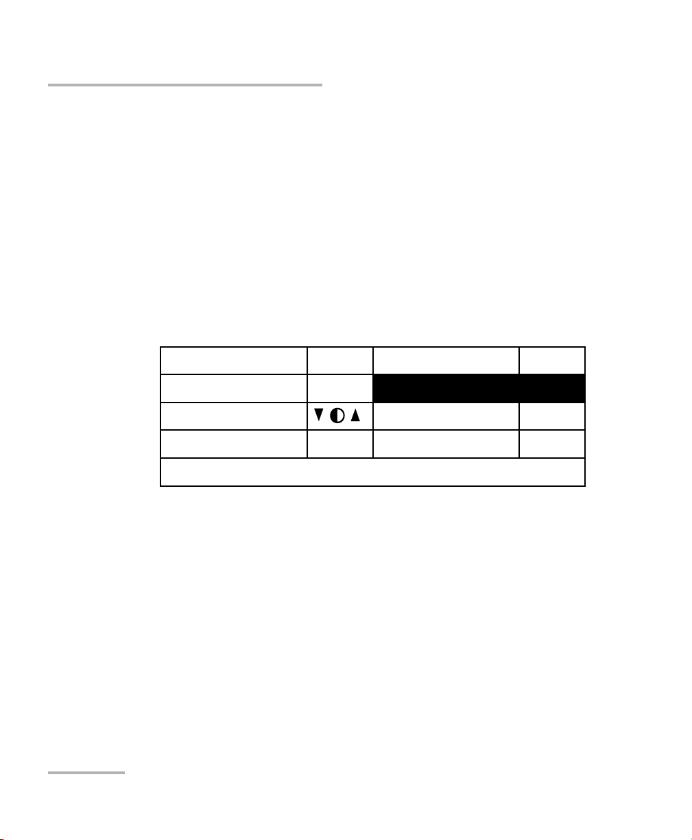
Setting the Contrast
To modify the contrast:
1. Press the Setup key.
2. Use the up/down or left/right arrow keys to select Contrast (item will
appear in reverse video).
3. Press ENTER to access the Contrast edit box.
4. Use the up/down arrow keys to adjust the contrast as required.
5. Press ENTER to confirm the contrast adjustment.
CD/PMD Analyzer Source 13
Page 20
Setting CD/PMD Analyzer Source Parameters
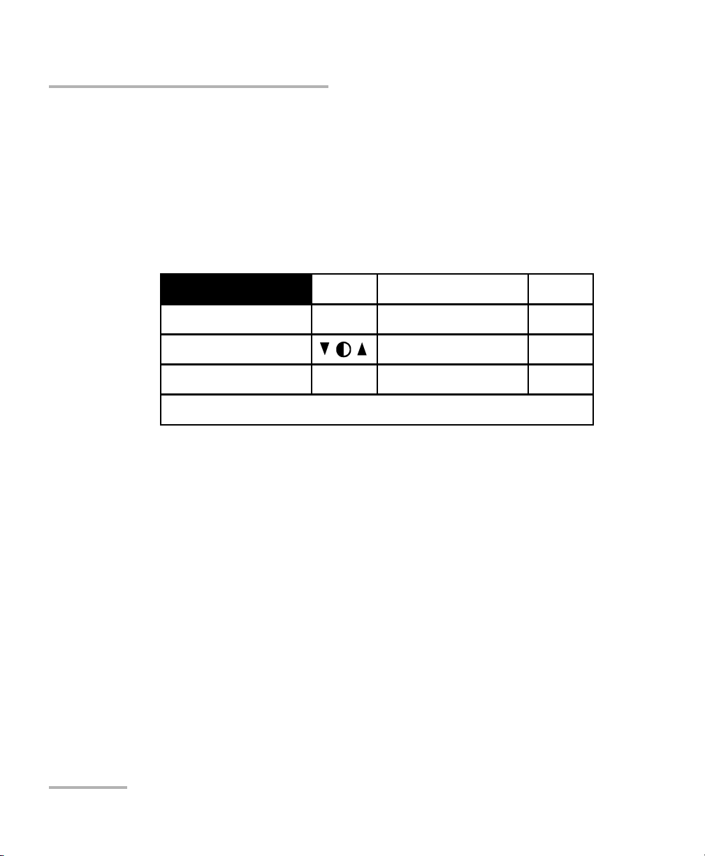
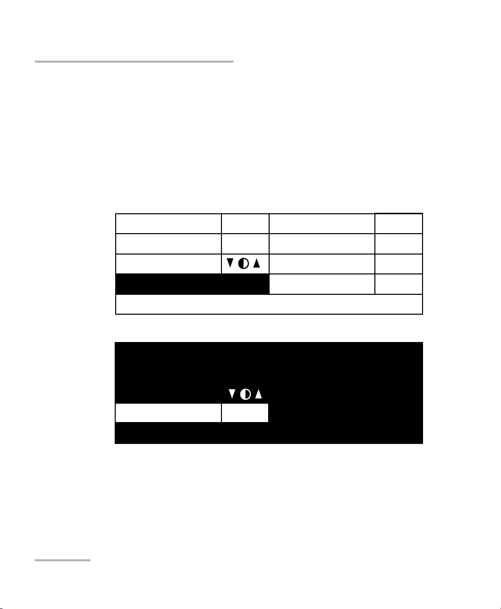
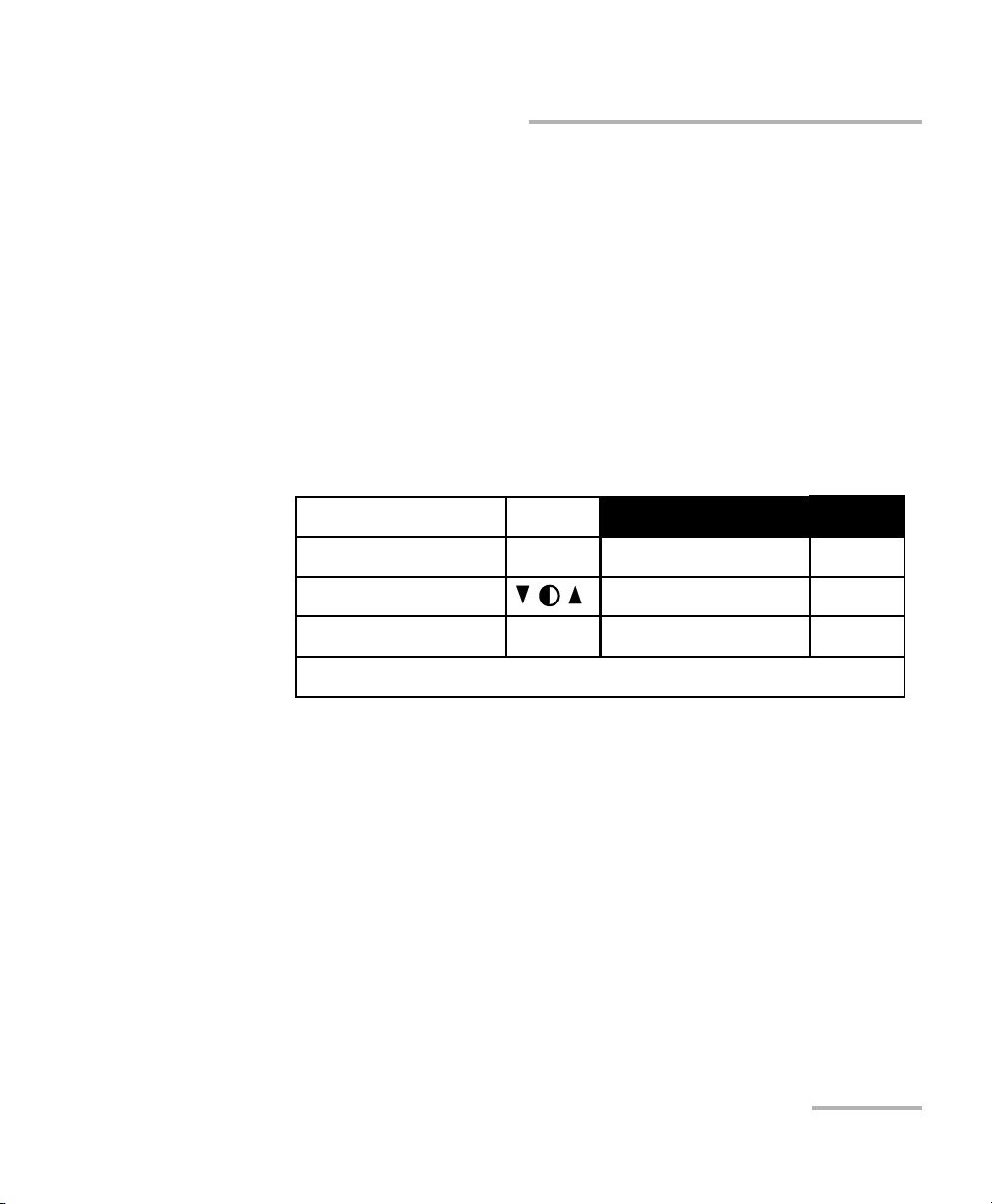
Setting the Video Mode
Setting the Video Mode
To change the video mode:
1. Press the Setup key.
2. Use the up/down or left/right arrow keys to select Video Mode (item
will appear in reverse video).
3. Press ENTER to access the Video Mode edit box.
4. Use the up/down arrow keys to set the required video mode.
Refresh Rate
Backlight
Contrast
Video Mode
8 Hz
ON
STD
RS232 / GPIB
GPIB Addr.
Baud Rate
Flow Ctrl
Exit
Refresh Rate
Backlight
8 Hz
ON
Contrast
Video Mode
Exit
Exit
5. Press ENTER to confirm the video mode.
INV
RS232 / GPIB
GPIB Addr.
Baud Rate
Baud Rate
Flow Ctrl
GPIB
12
N.A.
N.A.
GPIB
12
N.A.
N.A.
14 FLS-5834A
Page 21

Setting CD/PMD Analyzer Source Parameters
Resetting the CD/PMD Analyzer Source
Resetting the CD/PMD Analyzer Source
You may want to reset the CD/PMD Analyzer Source parameters to their
original values.
To reset parameters to values at time of purchase, while turning
on the unit:
Press ENTER until the unit beeps three times.
All the user-defined parameters are automatically reset. The following
table presents the parameters and their default values.
Parameters Reset Value or State
Source OFF
Backlight ON
Video mode STD (standard)
Refresh rate 4 Hz
RS232/GPIB (remote control)
GPIB address
Baud rate
Flow ctrl
a
a
a
a
GPIB
12
N.A.
N.A.
a. Parameter cannot be reset by a remote control command.
CD/PMD Analyzer Source 15
Page 22

Page 23

5 Operating the CD/PMD
Analyzer Source
Cleaning and Connecting Optical Fibers
IMPORTANT
To ensure maximum power and to avoid erroneous readings:
³ Always clean fiber ends as explained below before inserting
them into the port. EXFO is not responsible for damage or
errors caused by bad fiber cleaning or handling.
³ Ensure that your patchcord has appropriate connectors. Joining
mismatched connectors will damage the ferrules.
To connect the fiber-optic cable to the port:
1. Clean the fiber ends as follows:
1a. Gently wipe the fiber end with a lint-free swab dipped in isopropyl
alcohol.
1b. Use compressed air to dry completely.
1c. Visually inspect the fiber end to ensure its cleanliness.
2. Carefully align the connector and port to prevent the fiber end from
touching the outside of the port or rubbing against other surfaces.
If your connector features a key, ensure that it is fully fitted into the
port’s corresponding notch.
3. Push the connector in so that the fiber-optic cable is firmly in place,
thus ensuring adequate contact.
If your connector features a screwsleeve, tighten the connector
enough to firmly maintain the fiber in place. Do not overtighten, as this
will damage the fiber and the port.
Note: If your fiber-optic cable is not properly aligned and/or connected, you will
notice heavy loss and reflection.
CD/PMD Analyzer Source 17
Page 24
Operating the CD/PMD Analyzer Source
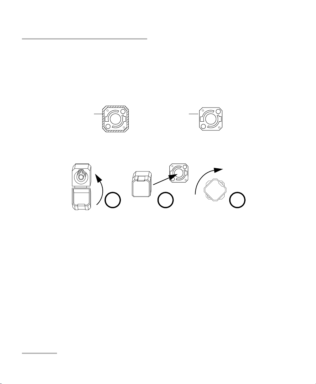
Installing the EXFO Universal Interface (EUI)
Installing the EXFO Universal Interface (EUI)
The EUI fixed baseplate is available for connectors with angled (APC) or
non-angled (UPC) polishing.A green border around the baseplate indicates
that it is for APC-type connectors.
Green border
indicates APC
option
Bare metal
(or blue border)
indicates UPC
option
To install an EUI connector adapter onto the EUI baseplate:
1. Hold the EUI connector adapter so the dust cap opens downwards.
2 3 4
2. Close the dust cap in order to hold the connector adapter more firmly.
3. Insert the connector adapter into the baseplate.
4. While pushing firmly, turn the connector adapter clockwise on the
baseplate to lock it in place.
18 FLS-5834A
Page 25
Operating the CD/PMD Analyzer Source
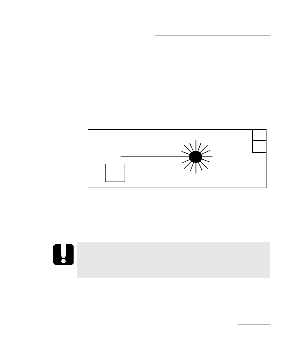
Activating or Deactivating the Source
Activating or Deactivating the Source
To activate the source:
1. Setup the source as explained in Setting CD/PMD Analyzer Source
Parameters on page 11.
2. To activate the source, press on the On/Off button. The active LED on
the module front will light up, and the front display will read "Source
ON", also showing a light beam icon.
The word "ON" will flash during the three-second safety delay.
RM
Source
C+ L
Band
Active source indicator
To deactivate the source:
To deactivate the source, press the On/Off button again. The active
LED on the module front will then turn off and the display will read
"Source OFF."
ON
LK
IMPORTANT
To obtain optimum stability, let the source warm up for 10 minutes.
If you do not respect this warmup time, the CD measurement will
present an uncertainty of 0.15 ps/nm.
CD/PMD Analyzer Source 19
Page 26

Page 27
6 Controlling the Source
Remotely
You can control the CD/PMD Analyzer Source remotely either by:
³ a GPIB interface (through a GPIB cable connected to the GPIB port)
or
³ an RS-232 interface (through a serial cable connected to the serial
port).
GPIB port
GPIB IEEE 488.2
SH1, AH1, T6, L4, SR1, RL1, PP0, DC1, DT1, C0, E2
This device complies with part 15 of the FCC rules. Operation is
subject to the following two conditions : (1) this device may not cause
harmful interference and (2) this devi ce must accept any interference
received, including interference that may cause undesired operation.
P/N
S/N
Made in Canada
Serial port (RS-232 DTE) Fuse holder
Ver.
Mfg.
date
QST-151
Serial Port
Electro-Optical Engineering
CUS
MODEL: GO
LR107723
R
100-240 V
50/60 Hz
2 A
F2AL250 V
Power
inlet
Ground
CD/PMD Analyzer Source 21
Page 28
Controlling the Source Remotely
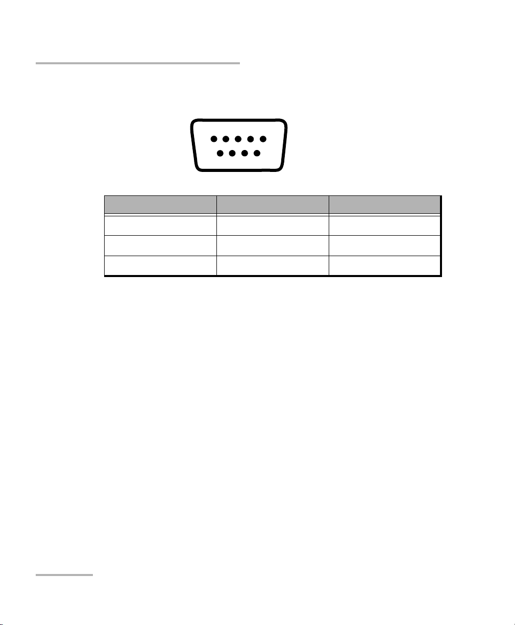
The RS-232 connector (serial port) at the back of the CD/PMD Analyzer
Source uses a DTE pinout configuration.
Pin Number Description Direction
2Receive (Rx)Input
3 Transmit (Tx) Output
5 Signal ground (Gnd) —
The commands used in both protocols are the same and are summarized
in two reference tables:
1234 5
6789
³ Common GPIB commands are listed in IEEE 488.2 Commands—Quick
Reference table on page 59.
³ Specific commands for the CD/PMD Analyzer Source are shown in the
Product-Specific Commands—Quick Reference table on page 81.
You can find detailed information in the Remonte Control Commands
appendix.
When the CD/PMD Analyzer Source is remotely controlled, RM appears in
the upper right-hand corner of the display.
22 FLS-5834A
Page 29
Controlling the Source Remotely
Setting the Remote Command Mode
Setting the Remote Command Mode
To remotely control the CD/PMD Analyzer Source, you must set a GPIB
address or activate the RS-232 port.
To set a remote command mode:
1. Press the Setup key.
2. Use the up/down or left/right arrow keys to select RS232 / GPIB. The
current setting is displayed.
Note: If GPIB is currently selected and you want to specify a GPIB address, see
Setting the GPIB Address on page 24.
Refresh Rate
Backlight
Contrast
Video Mode
8 Hz
ON
STD
RS232 / GPIB
GPIB Addr.
Baud Rate
Flow Ctrl
GPIB
12
N.A.
N.A.
Exit
3. Press ENTER to access the RS232 / GPIB edit box.
4. Use the up/down arrow keys to toggle between GPIB and RS232.
5. Press ENTER to confirm.
If you selected RS232, the GPIB Addr. menu option is deactivated (N.A. is
displayed).
If you selected GPIB, the Baud Rate and Flow Ctrl menu options are
disabled (N.A.is displayed). If necessary, you can change the GPIB address.
CD/PMD Analyzer Source 23
Page 30
Controlling the Source Remotely
Setting the GPIB Address
Setting the GPIB Address
If GPIB is selected as the remote command mode, you can select the GPIB
address you want to use from 1 to 30 (default value is 12).
To set a GPIB address:
1. Press the Setup key.
2. Use the up/down or left/right arrow keys to select GPIB Addr. The
current GPIB address is displayed.
Note: If you are in RS-232 mode, the GPIB address cell will display N.A. You m ust
change the communication mode to GPIB before setting an address.
Refresh Rate
Backlight
Contrast
Video Mode
8 Hz
ON
STD
RS232 / GPIB
GPIB Addr.
Baud Rate
Flow Ctrl
GPIB
12
N.A.
N.A.
Exit
3. Press ENTER, then use the up/down arrow keys to select a GPIB
address between 1 and 30.
4. Press ENTER to confirm your choice.
24 FLS-5834A
Page 31

Controlling the Source Remotely
Setting the Baud Rate
Setting the Baud Rate
The baud rate is a parameter related to RS-232 communication. It
determines the speed at which data is sent between the unit and a
computer, in bits per second (bps).
To change the baud rate for your remote communications:
1. Press the Setup key.
2. Use the up/down or left/right arrow keys to select Baud Rate. The
current setting is displayed.
Refresh Rate
Backlight
Contrast
Video Mode
8 Hz
ON
STD
RS232 / GPIB
GPIB Addr.
Baud Rate
Flow Ctrl
RS232
N.A.
19200
Soft
Exit
3. Press ENTER, then use the up/down arrow keys to select the baud rate.
You can select 1200, 2400, 4800, 9600 or 19200 bps.
4. Press ENTER to confirm.
CD/PMD Analyzer Source 25
Page 32

Controlling the Source Remotely
Setting the Flow Control
Setting the Flow Control
The flow control parameter applies only to RS-232 communication. This
parameter determines the type of serial communication used.
Choose Soft if you want the speed of data transmission to match the speed
at which the device can process it. This enables the computer and the
CD/PMD Analyzer Source to stop each other from transmitting by sending a
control character (Xoff). They will also be able to restart the transmission
by sending another control character (Xon). This is known as a software
handshake, a procedure requiring a special cable.
To set a flow control:
1. Press the Setup key.
2. Use the up/down or left/right arrow keys to select Flow Ctrl. The
current setting is displayed.
Refresh Rate
Backlight
Contrast
Video Mode
8 Hz
ON
STD
RS232 / GPIB
GPIB Addr.
Baud Rate
Flow Ctrl
RS232
N.A.
19200
Soft
Exit
3. Press ENTER, then use the up/down arrow keys to select the type of
flow you want. None means no flow control. Soft allows the unit or
computer controlling it, to turn the data transmission on or off.
4. Press ENTER to confirm.
26 FLS-5834A
Page 33

Controlling the Source Remotely
Communication Parameters
Communication Parameters
The communication parameters are used to set the communication port.
Note: EOS means “End of String.” EOI means “End or Identify.”
For GPIB Communication
Terminate Read on EOS Yes
Set EOI with EOS on Writes Yes
Type of compare on EOS 8 bits
EOS byte 0Ah
Send EOI at end of Writes Yes
GPIB primary address See Setting the GPIB Address on
page 24
GPIB secondary address None
For RS-232 Communication
EOS bytes 0Ah
Baud rate 1200/2400/4800/9600/ 19200 bps
Parity None
Data bits 8 bits
Stop bits 1 bit
Flow control Software (Xon/Xoff) or None
Activation See Setting the Remote Command
Mode on page 23
CD/PMD Analyzer Source 27
Page 34

Controlling the Source Remotely
Standard Status Data Structure
Standard Status Data Structure
The four tables below give information on the common status and enable
registers as defined by IEEE 488.2.
The diagram displayed on page 31 is a useful aid in understanding the
general commands and how a service request (SRQ) is generated.
³ Standard event status register (ESR)
Bits Mnemonics Bit Value
7 Power on 128
6Not used 0
5 Command error 32
4Execution error 16
3 Device dependent error 8
2Query error 4
1Not used 0
0 Operation complete 1
28 FLS-5834A
Page 35

Controlling the Source Remotely
³ Standard event status enable register (ESE)
Bits Mnemonics Bit Value
7 Power on 128
6Not used 0
5 Command error 32
4Execution error 16
3 Device dependent error 8
2Query error 4
1Not used 0
0 Operation complete 1
Standard Status Data Structure
CD/PMD Analyzer Source 29
Page 36

Controlling the Source Remotely
Standard Status Data Structure
³ Status byte register (STB)
Bits Mnemonics Bit Value
7Not used 0
6 Request service / Master
summary status
5 Event summary bit 32
4 Message available 16
3Not used 0
2 Error / Event queue 4
1Not used 0
0Not used 0
³ Service request enable register (SRE)
Bits Mnemonics Bit Value
7Not used 0
6Reserved 0
5 Event status byte 32
4 Message available 16
3Not used 0
64
2 Error / Event queue 4
1Not used 0
0Not used 0
30 FLS-5834A
Page 37

Controlling the Source Remotely
Standard Status Data Structure
Service Request
Generation
OR
OR
PON
7 6 5 4 3 2 1
EXECME
DDE
&
&
&
&
&
7 6 5 4 3 2 1 0
PON
7 6 5 4 3 2 1 0
{
RQS
MSS
6
EXECME
DDE
Message Output Queue not Empty
ESB MAV
&
&
&
&
OPC
QYE
Standard Event Status
0
Register (ESR)
&
&
&
Standard Event
Status Enable
Register (ESE)
OPC
QYE
Error / Event Ouput Queue not Empty
EEQ
Status Byte
Register
(STB)
&
&
&
read by serial poll
read by *STB?
7 5 4 3 2 1 0
{
ESB MAV EEQ
Service Request Enable
Register (SRE)
CD/PMD Analyzer Source 31
Page 38

Controlling the Source Remotely
Standard Status Data Structure
An SRQ is forced when a bit in the status byte register goes from 0 to 1 and
the corresponding SRE mask bit is set. If an SRQ is forced, the RQS bit is set
to 1 and will remain there until read by a serial poll –even if the reason or
condition causing the service request no longer exists. Similarly, if a serial
poll reads the RQS, it is reset to 0, whether or not the condition causing the
service request still exists.
32 FLS-5834A
Page 39

Controlling the Source Remotely
Command Structure
Command Structure
The GPIB and RS-232 commands follow the guidelines determined by the
Standard Commands for Programmable Instruments (SCPI) consortium.
For example, the following command syntax is used to activate or
deactivate the source.
SOUR:POW[:STAT]<wsp><Boolean>
³ SOUR, POW and STAT are keywords that define the function of the
command.
³ [ ] indicates that a keyword or parameter is optional.
³ <wsp> indicates that a space is required ("wsp" stands for "white
space").
³ <Boolean> indicates the command parameter.
³ Keywords must be separated by a colon.
To enter commands or queries you must use either the full word for the
command, or the three- or four-letter shortcut. Commands are not
case-sensitive, however spelling errors will cancel the command or query.
The command or query can be written using only shortcuts, only full
words, or a combination of both.
Other command syntax elements are:
³ The comma, which is used to separate values in a command or query.
³ The semi-colon, which is used to separate commands or queries,
when you send more than one at a time
Note: It is recommended that you retrieve the response immediately after
each query.
CD/PMD Analyzer Source 33
Page 40

Controlling the Source Remotely
Error Messages Format
Error Messages Format
System and device specific errors are managed by the FLS-5834A CD/PMD
Analyzer Source. The generic format for error messages is illustrated in the
following figure.
<Error number>
,
<Error
“
description>
<Device dependent
;
information>
As shown in the above figure, the message contains three parts:
³ Error number
³ Error description
³ Device dependent information
All error messages are stacked in a FIFO buffer. When there is at least one
message in the buffer, bit 2 of the status byte register is set to 1. Use the
SYST:ERR? command to read the most recent message. The error message
buffer is initialized when starting the CD/PMD Analyzer Source, when
executing the *CLS command, or by reading the last message stored in the
buffer.
Note: Error messages ending in a negative number are SCPI-based errors.
”
34 FLS-5834A
Page 41

7 Maintenance
To help ensure long, trouble-free operation:
³ Always clean fiber-optic connectors before using them.
³ Keep the unit free of dust.
³ Clean the unit casing and front panel with a cloth slightly dampened
with water.
³ Store unit at room temperature in a clean and dry area. Keep the unit
out of direct sunlight.
³ Avoid high humidity or significant temperature fluctuations.
³ Avoid unnecessary shocks and vibrations.
³ If any liquids are spilled on or into the unit, turn off the power
immediately and let the unit dry completely.
Use of controls, adjustments, and procedures for operation and
maintenance other than those specified herein may result in
hazardous radiation exposure.
WARNING
CD/PMD Analyzer Source 35
Page 42

Maintenance
Cleaning EUI Connectors
Cleaning EUI Connectors
Regular cleaning of EUI connectors will help maintain optimum
performance. There is no need to disassemble the unit.
If any damage occurs to internal connectors, the module casing will
have to be opened and a new calibration will be required.
To clean EUI connectors:
1. Remove the EUI from the instrument to expose the connector
baseplate and ferrule.
IMPORTANT
Turn
Push
2. Moisten a 2.5 mm cleaning tip with one drop of isopropyl alcohol
(alcohol may leave traces if used abundantly).
3. Slowly insert the cleaning tip into the EUI adapter until it comes out on
the other side (a slow clockwise rotating movement may help).
Pull
3
4
5
4. Gently turn the cleaning tip one full turn, then continue to turn as you
withdraw it.
36 FLS-5834A
Page 43

Cleaning EUI Connectors
5. Repeat steps 3 to 4 with a dry cleaning tip.
Note: Make sure you don’t touch the soft end of the cleaning tip.
6. Clean the ferrule in the connector port as follows:
6a. Deposit one drop of isopropyl alcohol on a lint-free wiping cloth.
IMPORTANT
Isopropyl alcohol may leave residues if used abundantly or left to
evaporate (about 10 seconds).
Avoid contact between the tip of the bottle and the wiping cloth,
and dry the surface quickly.
6b. Gently wipe the connector and ferrule.
6c. With a dry lint-free wiping cloth, gently wipe the same surfaces to
ensure that the connector and ferrule are perfectly dry.
6d. Verify connector surface with a portable fiber-optic microscope
(e.g., EXFO’s FOMS) or fiber inspection probe (e.g., EXFO’s FIP).
Maintenance
WARNING
Verifying the surface of the connector WHILE THE UNIT IS ACTIVE
WILL result in permanent eye damage.
7. Put the EUI back onto the instrument (push and turn clockwise).
8. Throw out cleaning tips and wiping cloths after one use.
CD/PMD Analyzer Source 37
Page 44

Maintenance
Replacing Fuses
Replacing Fuses
The FLS-5834A CD/PMD Analyzer Source contains two F2.0L250V-type fuses
(IEC, 5 mm x 20 mm (0.197 in x 0.787 in), fast-acting, low breaking
capacity, 250 V). The fuse holder is located at the back of the CD/PMD
Analyzer Source, just beside the power inlet.
To replace a fuse:
1. Turn off the unit and disconnect the power cord.
2. Using a flat-head screwdriver as a lever, pull out the fuse holder.
Fuse holder
3. Verify and replace the fuses as necessary.
38 FLS-5834A
Page 45

Maintenance
Recalibrating the Unit
4. Insert the new fuses into the fuse holder.
Fuse
Fuse holder
5. Ensure the fuses are placed firmly in the holder before reinstalling it in
the unit.
6. Firmly push the fuse holder back into place.
Recalibrating the Unit
Manufacturing and service center calibrations are based on the
ISO/IEC 17025 Standard, which states that calibration documents must not
contain a recommended calibration interval, unless this has been
previously agreed upon with the customer.
Validity of specifications depends on operating conditions. For example,
the calibration validity period can be longer or shorter depending on the
intensity of use, environmental conditions and unit maintenance. You
should determine the adequate calibration interval for your unit according
to your accuracy requirements.
Under normal use, EXFO recommends calibrating your unit every year.
CD/PMD Analyzer Source 39
Page 46

Maintenance
Upgrading the Embedded Software
Upgrading the Embedded Software
To upgrade the CD/PMD Analyzer Source embedded software, you will
need to obtain the upgrade files from EXFO’s Technical Support Group. You
will also need a null-modem cable.
You may upgrade software under DOS, Windows 3.1, Windows 9x,
or Windows 2000. With some notebook computers, you may need
to be under a DOS environment. If problems occur, contact EXFO.
To upgrade the embedded software:
1. Turn off the CD/PMD Analyzer Source.
2. Connect a null-modem cable to the CD/PMD Analyzer Source RS-232
port and to an unused serial communication port on your computer.
3. On your computer’s hard disk, create a folder named “Test” (C:\Test).
4. Unzip or copy the upgrade files into the newly created folder.
IMPORTANT
5. If the software upgrade is performed under Windows 98, you must
restart your computer in DOS mode before starting the upgrade
program. In other cases, simply exit to DOS.
6. Go to the “C:\Test” folder and start the upgrade program by typing the
following line (spaces are required between parameters):
Lo0006.exe /C:2 /F:c:\test\filename.hex /S:19200
Parameters can be decoded as follows:
³ /C: serial port number (COM2 in the above example)
³ /F: file to copy on your unit (replace “filename” with the actual
name of the .hex file on your hard disk)
³ /S: computer-to-unit transfer speed (if “19200” does not work, try
“56700”)
40 FLS-5834A
Page 47

Maintenance
Upgrading the Embedded Software
7. When a message about waiting for a evice handshake appears, turn on
the CD/PMD Analyzer Source.
The unit display remains off, the unit beeps once and the upgrade
program starts automatically. A progress bar on the computer screen
indicates the upgrade status. Once the software upgrade is complete,
the message about restarting the unit appears.
8. If the software upgrade was performed under Windows 2000, an error
message to the effect that the LO0006 NTVDM has encountered a
system error and to select close to terminate the application is
displayed. Click Close to hide the dialog box.
9. Turn the CD/PMD Analyzer Source off, and then on again.
Some units will display the new version number at startup, otherwise
press the up and right arrow keys together while the unit is turned on.
CD/PMD Analyzer Source 41
Page 48

Maintenance
Recycling and Disposal (Applies to European Union Only)
Recycling and Disposal
(Applies to European Union Only)
Recycle or dispose of your product (including electric and
electronic accessories) properly, in accordance with local
regulations. Do not dispose of it in ordinary garbage receptacles.
This equipment was sold after August 13, 2005 (as identified by
the black rectangle).
³ Unless otherwise noted in a separate agreement between EXFO and a
customer, distributor or commercial partner, EXFO will cover costs
related to the collection, treatment, recovery and disposal of
end-of-lifecycle waste generated by electronic equipment introduced
after August 13, 2005 to an European Union member state with
legislation regarding Directive 2002/96/EC.
³ Except for reasons of safety or environmental benefit, equipment
manufactured by EXFO, under its brand name, is generally designed to
facilitate dismantling and reclamation.
For complete recycling/disposal procedures and contact information, visit
the EXFO Web site at www.exfo.com/recycle.
42 FLS-5834A
Page 49

8 Troubleshooting
CD/PMD Analyzer Source Error Messages
Warning/Error
Number
-11 Module reset error:
The nulling was not performed
correctly.
-12 Wrong module ID:
The module returns the wrong ID.
-20 Module communication error:
Communication error with the
module.
-25 Checksum error:
Checksum error while reading the
module’s FIFO.
-30 Command not accepted:
The command that caused the
warning will be lost. The unit may
continue with the program even if the
command was not performed.
-31 Module setting error:
One of the settings sent to the unit is
wrong.
Description Recommended Action
Restart your unit to solve the
problem.
Call EXFO for assistance.
Restart your unit to solve the
problem.
Restart your unit to solve the
problem.
If problem persists, call EXFO for
assistance.
Review your command before
sending it again.
-32 Action currently in progress:
You cannot send a command while
the unit is already active.
-34 Command overflow:
Too many commands were sent to
the unit at a time.
CD/PMD Analyzer Source 43
Wait until the unit is done before
sending the command.
Wait until the unit is done before
sending more commands.
Page 50

Troubleshooting
CD/PMD Analyzer Source Error Messages
Warning/Error
Number
Description Recommended Action
-40 FIFO not ready for reading:
The unit’s FIFO is not ready for
reading. Commands sent will be
ignored.
-60 Laser over-current:
A problem occurred with the current
going to the laser.
-64 EEPROM error:
The EEPROM was not detected.
-65 EEPROM checksum error:
A checksum error was detected by
the unit.
-68 Temperature error:
The operating temperature of the unit
is from 10 °C to 40 °C (50 °F to 104 °F).
-69 FPGA problem:
An FPGA problem was detected.
If problem persists, call EXFO for
assistance.
Call EXFO for assistance.
Call EXFO for assistance.
Call EXFO for assistance.
Make sure the ambient
temperature remains within the
specified temperature range.
Call EXFO for assistance.
-73 Supply voltage error:
Call EXFO for assistance.
Internal voltage values are out of the
operation range.
-74 Laser pump failure:
Call EXFO for assistance.
A problem occurred in the output
(optical) power of the laser pump.
-75 Laser temperature problem:
Laser temperature is out of the
operation range.
44 FLS-5834A
Make sure the ambient
temperature remains within the
specified temperature range.
Page 51

Troubleshooting
CD/PMD Analyzer Source Error Messages
Warning/Error
Number
Description Recommended Action
-76 Thermo-electric cooler over-current:
A problem occurred with the current
going to the thermo-electric cooler.
-79 EEPROM access error:
A problem occurred when accessing
the EEPROM memory (read or write).
100 No more room in the command pipe:
A command could not be added to
the command pipe.
101 Timeout error:
The command request was not
performed in the set time amount.
102 Runtime error:
The command was not performed by
the unit due to a runtime error.
103 Invalid response:
A command has triggered an invalid
response from the unit.
Call EXFO for assistance.
Call EXFO for assistance.
If problem persists, call EXFO for
assistance.
Call EXFO for assistance.
Call EXFO for assistance.
Call EXFO for assistance.
200 Decompression error:
Call EXFO for assistance.
An error occurred while
decompressing the software.
32244 Floating exception:
There is an overflow while running a
Restart your unit to solve the
problem.
command.
32245 Stack overflow:
Not enough RAM to run the
Restart your unit to solve the
problem.
command.
CD/PMD Analyzer Source 45
Page 52

Troubleshooting
CD/PMD Analyzer Source Error Messages
Warning/Error
Number
Description Recommended Action
32246 Abort called in firmware:
The unit used a command which it is
not intended to.
32300 Heap overflow:
Not enough space in the heap.
32301
32302
Malloc overflow:
Not enough RAM to run the
command.
32303 Divide by zero:
The unit attempted to perform a
division by zero, which gives an
infinite answer.
32304 Array boundary error:
A table index is outside the
boundaries set by the array.
32305 Invalid Opcode:
The unit did not recognize the binary
code.
Restart your unit to solve the
problem.
Restart your unit to solve the
problem.
Restart your unit to solve the
problem.
Restart your unit to solve the
problem.
Restart your unit to solve the
problem.
Restart your unit to solve the
problem.
46 FLS-5834A
Page 53

Troubleshooting
GPIB Troubleshooting
GPIB Troubleshooting
Problem Probable Cause Solution
Unable to communicate
with CD/PMD Analyzer
Source (no response from
*IDN? command).
Receive “Undefined
header” error.
Unstable communication. Incorrect termination
Incorrect
communication type
selected.
Incorrect
communication
parameters.
Incorrect termination
characters.
Poor bus connection. Ensure the functionning of the
Improper configuration. Verify that the GPIB interface is
Incorrect command
syntax.
character.
Select the correct
communication type: RS-232 or
GPIB.
Check the communication
parameters: bus address, baud
rate, flow control, etc., as
required.
Synchronize termination
characters between the GPIB
controller and the SCPI manager.
controller card and make sure
that the bus cable is properly
connected.
properly configured.
Verify and correct syntax.
Synchronize termination
characters between the GPIB
controller and the SCPI manager.
CD/PMD Analyzer Source 47
Page 54

Troubleshooting
Finding Information on the EXFO Web Site
Finding Information on the EXFO Web Site
The EXFO Web site provides answers to frequently asked questions (FAQs)
regarding the use of your FLS-5834A CD/PMD Analyzer Source.
To access FAQs:
1. Ty pe http://www.exfo.com in your Internet browser.
2. Click the Support tab.
3. Click FAQs and follow the on-screen instructions. You will be given a
list of questions pertaining to your subject.
The EXFO Web site also provides the product’s most recent technical
specifications.
48 FLS-5834A
Page 55

Troubleshooting
Contacting the Technical Support Group
Contacting the Technical Support Group
To obtain after-sales service or technical support for this product, contact
EXFO at one of the following numbers. The Technical Support Group is
available to take your calls from Monday to Friday, 7:30 a.m. to 8:00 p.m.
(Eastern Time in North America).
Technical Support Group
400 Godin Avenue
Quebec (Quebec) G1M 2K2
CANADA
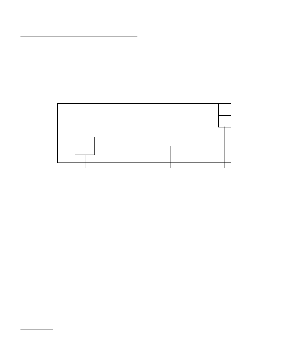
To accelerate the process, please have information such as the name and
the serial number (see the product identification label—an example is
shown below), as well as a description of your problem, close at hand.
1 866 683-0155 (USA and Canada)
Tel.: 1 418 683-5498
Fax: 1 418 683-9224
support@exfo.com
P/N
**************** A
542392-3D
S/N
Made in Canada QST442B
January 2020
Ver.
Mfg.
date
465 Godin Avenue
Vanier (Quebec) G1M 3G7 CANADA
FLS-5834A-XX
Connector
CD/PMD Analyzer Source 49
Page 56

Troubleshooting
Transportation
Transportation
Maintain a temperature range within specifications when transporting the
unit. Transportation damage can occur from improper handling. The
following steps are recommended to minimize the possibility of damage:
³ Pack the unit in its original packing material when shipping.
³ Avoid high humidity or large temperature fluctuations.
³ Keep the unit out of direct sunlight.
³ Avoid unnecessary shocks and vibrations.
50 FLS-5834A
Page 57

9 Warranty
General Information
EXFO Electro-Optical Engineering Inc. (EXFO) warrants this equipment
against defects in material and workmanship for a period oftwo years from
the date of original shipment. EXFO also warrants that this equipment will
meet applicable specifications under normal use.
During the warranty period, EXFO will, at its discretion, repair, replace,
or issue credit for any defective product, as well as verify and adjust the
product free of charge should the equipment need to be repaired or if the
original calibration is erroneous. If the equipment is sent back for
verification of calibration during the warranty period and found to meet all
published specifications, EXFO will charge standard calibration fees.
The warranty can become null and void if:
³ unit has been tampered with, repaired, or worked upon by
unauthorized individuals or non-EXFO personnel.
³ warranty sticker has been removed.
IMPORTANT
³ case screws, other than those specified in this guide, have been
removed.
³ case has been opened, other than as explained in this guide.
³ unit serial number has been altered, erased, or removed.
³ unit has been misused, neglected, or damaged by accident.
THIS WARRANTY IS IN LIEU OF ALL OTHER WARRANTIES EXPRESSED,
IMPLIED, OR STATUTORY, INCLUDING, BUT NOT LIMITED TO, THE
IMPLIED WARRANTIES OF MERCHANTABILITY AND FITNESS FOR A
PARTICULAR PURPOSE. IN NO EVENT SHALL EXFO BE LIABLE FOR
SPECIAL, INCIDENTAL, OR CONSEQUENTIAL DAMAGES.
CD/PMD Analyzer Source 51
Page 58

Warranty
Liability
Liability
EXFO shall not be liable for damages resulting from the use of the product,
nor shall be responsible for any failure in the performance of other items to
which the product is connected or the operation of any system of which
the product may be a part.
EXFO shall not be liable for damages resulting from improper usage or
unauthorized modification of the product, its accompanying accessories
and software.
Exclusions
EXFO reserves the right to make changes in the design or construction of
any of its products at any time without incurring obligation to make any
changes whatsoever on units purchased. Accessories, including but not
limited to fuses, pilot lamps, batteries and universal interfaces (EUI) used
with EXFO products are not covered by this warranty.
This warranty excludes failure resulting from: improper use or installation,
normal wear and tear, accident, abuse, neglect, fire, water, lightning or
other acts of nature, causes external to the product or other factors beyond
EXFO’s control.
IMPORTANT
EXFO will charge a fee for replacing optical connectors that were
damaged due to misuse or bad cleaning.
Certification
EXFO certifies that this equipment met its published specifications at the
time of shipment from the factory.
52 FLS-5834A
Page 59

Warranty
Service and Repairs
Service and Repairs
EXFO commits to providing product service and repair for five years
following the date of purchase.
To send any equipment for service or repair:
1. Call one of EXFO’s authorized service centers (see EXFO Service
Centers Worldwide on page 54). Support personnel will determine if
the equipment requires service, repair, or calibration.
2. If equipment must be returned to EXFO or an authorized service
center, support personnel will issue a Return Merchandise
Authorization (RMA) number and provide an address for return.
3. If possible, back up your data before sending the unit for repair.
4. Pack the equipment in its original shipping material. Be sure to include
a statement or report fully detailing the defect and the conditions under
which it was observed.
5. Return the equipment, prepaid, to the address given to you by support
personnel. Be sure to write the RMA number on the shipping slip. EXFO
will refuse and return any package that does not bear an RMA number.
Note: A test setup fee will apply to any returned unit that, after test, is found to
meet the applicable specifications.
After repair, the equipment will be returned with a repair report. If the
equipment is not under warranty, you will be invoiced for the cost
appearing on this report. EXFO will pay return-to-customer shipping costs
for equipment under warranty. Shipping insurance is at your expense.
Routine recalibration is not included in any of the warranty plans. Since
calibrations/verifications are not covered by the basic or extended
warranties, you may elect to purchase FlexCare Calibration/Verification
Packages for a definite period of time. Contact an authorized service center
(see EXFO Service Centers Worldwide on page 54).
CD/PMD Analyzer Source 53
Page 60

Warranty
EXFO Service Centers Worldwide
EXFO Service Centers Worldwide
If your product requires servicing, contact your nearest authorized service
center.
EXFO Headquarters Service Center
400 Godin Avenue
Quebec (Quebec) G1M 2K2
CANADA
EXFO Europe Service Center
Omega Enterprise Park, Electron Way
Chandlers Ford, Hampshire S053 4SE
ENGLAND
EXFO China Service Center/
Beijing OSIC
Beijing New Century Hotel
Office Tower, Room 1754-1755
No. 6 Southern Capital Gym Road
Beijing 100044
P. R . C H I N A
1 866 683-0155 (USA and Canada)
Tel.: 1 418 683-5498
Fax: 1 418 683-9224
quebec.service@exfo.com
Tel.: +44 2380 246810
Fax: +44 2380 246801
europe.service@exfo.com
Tel.: +86 (10) 6849 2738
Fax: +86 (10) 6849 2662
beijing.service@exfo.com
54 FLS-5834A
Page 61

A Technical Specifications
SPECIFICATIONS
a
GENERAL SPECIF ICATIONS
a
NOTES
a. Typical
SPECIFICATIONS
a
Center wavelength (nm) 1580 ±20
Output power (dBm) 4
Peak spectral density (dBm/nm)
>—12.5
Power stability (15 minutes) (dB)
< 0.075
Modulation frequency (MHz) 100
GENERAL SPECI FICATIONS
Temperature
operating 0 °C to 40 °C (32 °F to 104 °F)
storing —20 °C to 50 °C (—4 °F to 122 °F)
Relative humidity (non-condensing) 0 % to 90 %
Size (H x W x D) 116 mm x 218 mm x 340 mm (
45/8in x 83/4in x 131/8in
)
Weight (without transceivers) 3.2 kg (7.1 lb)
IMPORTANT
The following technical specifications can change without notice.
The information presented in this section is provided as a reference
only. To obtain this product’s most recent technical specifications,
visit the EXFO Web site at www.exfo.com.
CD/PMD Analyzer Source 55
Page 62

Page 63

B Rackmount Installation
You can place your FLS-5834A CD/PMD Analyzer Source in a rackmount to
facilitate its usage.
To install the rackmount:
1. Fix the angle iron using four flat Phillips screws.
3
2
4
1
2. Fix the rackmount bracket to the frame using two round Phillips
screws.
3. Fix the rackmount stiffener using two flat Phillips screws (for the front
panel) and two round Phillips screws.
4. If your rackmount will contain only one unit, fix the rackmount cover
plate to the empty part of the frame using four flat Phillips screws.
CD/PMD Analyzer Source 57
Page 64

Rackmount Installation
To install your FLS-5834A CD/PMD Analyzer Source in a
rackmount:
1. Slide the benchtop unit into the rackmount and tighten it from
underneath using the four cover fixing screws.
If measurement X on the illustration exceeds 11.125 in., fix the unit into
the four holes identified as A. Otherwise, use the other four holes.
X
A
2. If a second benchtop is to be installed, remove the cover plate and
repeat step 1.
58 FLS-5834A
Page 65

C Remote Control Commands
IEEE 488.2 Commands—Quick Reference
The CD/PMD Analyzer Source recognizes the required commands
identified in IEEE 488.2. The table below summarizes these commands.
Command Function
*CLS Clear status command
*ESE Standard event status enable command
*ESE? Standard event status enable query
*ESR? Standard event status register query
*IDN? Identification query
a
*LOK
a
*LOK?
*OPC Operation complete command
*OPC? Operation complete query
a
*REM
Set Remote Lockout programming state
Remote Lockout programming state query
Set Remote programming state
*RST Reset command
*SRE Service request enable command
*SRE? Service request enable query
*STB? Read status byte query
*TST? Self-test query
*WAI Wait for pending operations to be completed
a. This command can only be used with RS-232 communication.
CD/PMD Analyzer Source 59
Page 66

Remote Control Commands
IEEE 488.2 Commands—Description
IEEE 488.2 Commands—Description
Description The *CLS command clears the Standard Event
Syntax *CLS
Parameter(s) None
Description The *ESE command sets the Standard Event
*CLS
Status Register and the Error/Event Queue.
*ESE
Status Enable Register bits, as defined in the
table below. This register contains a mask value
for the bits to be enabled in the Standard Event
Status Register.
MSB LSBStandard Event Status Enable Register
PON CME EXE DDE QYE N.U. OPC
N.U.
Syntax *ESE<wsp><RegisterValue>
Parameter(s) RegisterValue:
The program data syntax for <RegisterValue> is
defined as a <DECIMAL NUMERIC PROGRAM
DATA> element.
The <RegisterValue>, expressed in base 2,
represents the bit values of the Standard Event
Status Enable Register.
60 FLS-5834A
Page 67

Remote Control Commands
IEEE 488.2 Commands—Description
*ESE
The table below shows the contents of this
register.
Bit Weight Meaning
PON 128 Power ON Enable
N.U. 64 Not used
CMD 32 CoMmanD Error Enable
EXE 16 Execution Error Enable
DDE 8 Device Dependent Error Enable
QRY 4 QueRry Error Enable
N.U. 2 Not used
OPC 1 Operation Complete Enable
A value of 1 in the Enable Register enables the
corresponding bit in the Status Register, a value
of 0 disables the bit. The value of the
<RegisterValue> shall be in the range of 0
through 255.
Example(s) *ESE 25
where 25 = (bit EXE, bit DDE and bit OPC)
*ESE 0
clears the content of the Standard Event Status
Enable register
See Also *ESE?
*ESR?
CD/PMD Analyzer Source 61
Page 68

Remote Control Commands
IEEE 488.2 Commands—Description
Description The *ESE? query allows the programmer to
Syntax *ESE?
Parameter(s) None
Response Syntax <RegisterValue>
*ESE?
determine the current contents of the Standard
Event Status Enable Register. See the contents of
this register below.
MSB LSBStandard Event Status Enable Register
PON CME EXE DDE QYE N.U. OPC
N.U.
62 FLS-5834A
Page 69

Response(s) RegisterValue:
The response data syntax for <RegisterValue> is
defined as a <NR1 NUMERIC RESPONSE DATA>
element.
The <RegisterValue> ranges from 0 through 255.
The <RegisterValue> value expressed in base 2
(binary) represents the bit values of the Standard
Event Status Enable register. See below.
Bit Weight Meaning
PON 128 Power ON Enable
N.U. 64 Not used
CMD 32 CoMmanD Error Enable
EXE 16 Execution Error Enable
DDE 8 Device Dependent Error Enable
Remote Control Commands
IEEE 488.2 Commands—Description
*ESE?
QRY 4 QueRry Error Enable
N.U. 2 Not used
OPC 1 Operation Complete Enable
Example(s) *ESE? returns 133
where 133 = (bit PON, bit QYE and bit OPC)
See Also *ESE
*ESR?
CD/PMD Analyzer Source 63
Page 70

Remote Control Commands
IEEE 488.2 Commands—Description
Description The *ESR? query allows the programmer to
Syntax *ESR?
Parameter(s) None
Response Syntax <RegisterValue>
*ESR?
determine the current contents of the Standard
Event Status Register. Reading the Standard
Event Status Register clears it. See the contents of
this register below.
MSB LSBStandard Event Status Enable Register
PON CME EXE DDE QYE N.U. OPC
N.U.
64 FLS-5834A
Page 71

Response(s) RegisterValue:
The response data syntax for <RegisterValue> is
defined as a <NR1 NUMERIC RESPONSE DATA>
element.
The <RegisterValue> ranges from 0 through 255.
The <RegisterValue> value expressed in base 2
(binary) represents the bit values of the Standard
Event Status register. See below.
Bit Weight Meaning
PON 128 Power ON Enable
N.U. 64 Not used
CMD 32 CoMmanD Error Enable
EXE 16 Execution Error Enable
DDE 8 Device Dependent Error Enable
Remote Control Commands
IEEE 488.2 Commands—Description
*ESR?
QRY 4 QueRry Error Enable
N.U. 2 Not used
OPC 1 Operation Complete Enable
Example(s) *ESR? returns 33
where 33 = (bit CME and bit OPC)
See Also *ESE
*ESE?
CD/PMD Analyzer Source 65
Page 72

Remote Control Commands
IEEE 488.2 Commands—Description
Description The intent of the *IDN? query is for the unique
Syntax *IDN?
Response(s) “EXFO E.-O. Engineering,FLS-5834A,xxxxxxxxxx,
Description This command is used to set the Remote
*IDN?
identification of devices over the system
interface.
2.0r0”, where
– xxxxxxxx is the serial number
– 2.0r0 is the Firmware level.
*LOK
Lockout programming state.
Syntax *LOK<wsp><LockoutState>
Parameter(s) LockoutState:
The program data syntax for <LockoutState> is
defined as a <Boolean Program Data> element.
The <LockoutState>special forms ON and OFF
are accepted on input for increased readibility.
ON corresponds to 1 and OFF to 0.
The <LockoutState> parameter is the new
lockout state of the CD/PMD Analyzer Source:
“0”- Removing the Lockout state of the source.
“1”- Enabling the Lockout state of the source.
66 FLS-5834A
Page 73

Remote Control Commands
IEEE 488.2 Commands—Description
*LOK
Example(s) *LOK 1
Notes This command can only be used when working
with RS-232 communication.
See Also *LOK?
CD/PMD Analyzer Source 67
Page 74

Remote Control Commands
IEEE 488.2 Commands—Description
Description This query returns the Remote Lockout
Syntax *LOK?
Parameter(s) None
Response Syntax <LockoutState>
Response LockoutState:
*LOK?
programming state indicating if the CD/PMD
Analyzer Source has been locked out by a
remote application.
The response data syntax for <LockoutState> is
defined as an <NR1 NUMERIC RESPONSE
DATA> element.
The <LockoutState> response corresponds to
the remote lockout state of the CD/PMD Analyzer
Source:
“0”- The source is unlocked.
“1”- The source is locked.
Example(s) *LOK? returns 1
Notes This command can only be used when working
with RS-232 communication.
See Also *LOK
68 FLS-5834A
Page 75

Remote Control Commands
IEEE 488.2 Commands—Description
*OPC
Description The *OPC command allows synchronization
between the instrument and an external
controller.
The *OPC command causes the instrument to
set bit 0 (Operation Complete) in the Standard
Event Status Register to the TRUE (logic 1) state
when the instrument completes all pending
operations.
Detection of the Operation Complete message
can be accomplished by continuous polling of
the Standard Event Status Register using the
*ESR? common query command. However,
using a service request eliminates the need to
poll the Standard Event Status Register thereby
freeing the controller to do other useful work.
Syntax *OPC
Parameter(s) None
See Also *OPC?
*WAI
CD/PMD Analyzer Source 69
Page 76

Remote Control Commands
IEEE 488.2 Commands—Description
Description The *OPC? query allows synchronization
Syntax *OPC?
Parameter(s) None
Response Syntax <Acknowledge>
*OPC?
between the instrument and an external
controller by reading the Output Queue or by
waiting for a service request on the Message
Available (MAV) bit in the Status Byte Register.
The *OPC? query causes the instrument to place
an ASCII character, 1, into its Output Queue
when the device completes all pending
operations. A consequence of this action is that
the MAV bit in the Status Byte Register is set to
state 1.
Response(s) Acknowledge:
The response data syntax for <Acknowledge> is
defined as a <NR1 NUMERIC RESPONSE DATA>
element.
The <Acknowledge> response is a single
ASCII-encoded byte corresponding to 1.
The receipt of an <Acknowledge> response
indicates that all pending selected device
operations have been completed.
Example(s) *OPC? Return 1
See Also *OPC
*WAI
70 FLS-5834A
Page 77

Remote Control Commands
IEEE 488.2 Commands—Description
Description This command is used to set the Remote
programming state that determines if the source
will be controlled locally or remotely.
Syntax *REM<wsp><RemoteState>
Parameter(s) RemoteState:
The program syntax data for <RemoteState> is
defined as a <Boolean Program Data> element.
The <RemoteState> special forms ON and OFF
are accepted on input for increased readibility.
ON corresponds to 1 and OFF to 0.
The <RemoteState> parameter is the new
remote state of the CD/PMD Analyzer Source:
“0”- to set Local state.
“1”- to set Remote state.
*REM
Example(s) *REM 1
Notes This command can only be used with RS-232
communication.
CD/PMD Analyzer Source 71
Page 78

Remote Control Commands
IEEE 488.2 Commands—Description
Description The *RST command performs a device reset.
*RST
This command is the third reset level in a
three-level reset strategy. The Reset command
shall do the following:
a) Sets the device-specific functions to a known
state that is independent of the past-use history
of the device.
b) Forces the device into OCIS state (Operation
complete Command Idle State).
c) Forces the device into OQIS state (Operation
complete Query Idle State).
The Reset command explicitly DOES NOT affect
the following:
a) The state of the Communication interface.
b) The Output Queue.
c) Any Event Enable Register setting, including
the Standard Event Status Enable Register setting.
d) Any Event Register setting, including the
Standard Event Status Register settings.
e) Calibration data that affects device
specifications.
f) The Service Request Enable Register setting.
Syntax *RST
Parameter(s) None
72 FLS-5834A
Page 79

Remote Control Commands
IEEE 488.2 Commands—Description
*SRE
Description The *SRE command sets the Service Request
Enable Register bits. See the contents of this
register below. This register contains a mask
value to enable the bits in the Status Byte
Register.
MSB LSB
N.U. N.U. ESB MAV N.U. EAV N.U. N.U.
Serv ice Reques t Enable
Register
Syntax *SRE<wsp><RegisterValue>
Parameter(s) RegisterValue:
The program data syntax for <RegisterValue> is
defined as a <DECIMAL NUMERIC PROGRAM
DATA> element.
The <RegisterValue> value ranges from 0
through 255.
The <RegisterValue>, expressed in base 2
(binary), represents the bit values of the Service
Request Enable Register.
CD/PMD Analyzer Source 73
Page 80

Remote Control Commands
IEEE 488.2 Commands—Description
*SRE
See the contents of this register below.
Bit Weight Meaning
N.U. 128 Not used
N.U. 64 Not used
ESB 32 Event Summary Bit Enable
MAV 16 Message AVailable Enable
N.U. 8 Not used
EAV 4 Error / Event AVailable Enable
N.U. 2 Not used
N.U. 1 Not used
A bit value of zero shall indicate a disabled
condition.
Example(s) *SRE 52
where 52 = (bit ESB, bit MAV and bit EAV)
See Also *SRE?
*STB?
74 FLS-5834A
Page 81

Remote Control Commands
IEEE 488.2 Commands—Description
*SRE?
Description The *SRE? query allows the programmer to
determine the current contents of the Service
Request Enable Register. See the contents of this
register below.
MSB LSB
N.U. N.U. ESB MAV N.U. EAV N.U. N.U.
Bit Weight Meaning
N.U. 128 Not used
N.U. 64 Not used
ESB 32 Event Summary Bit Enable
MAV 16 Message AVailable Enable
N.U. 8 Not used
EAV 4 Error / Event AVailable Enable
N.U. 2 Not used
N.U. 1 Not used
Syntax *SRE?
Parameter(s) None
Response Syntax <RegisterValue>
Serv ice Reques t Enable
Register
CD/PMD Analyzer Source 75
Page 82

Remote Control Commands
IEEE 488.2 Commands—Description
Response(s) RegisterValue:
Example(s) *SRE Return 32 (bit ESB)
See Also *SRE
*SRE?
The response data syntax for <RegisterValue> is
defined as a <NR1 NUMERIC RESPONSE DATA>
element.
The <RegisterValue> ranges from 0 through 255.
When converted to binary (base 2), the
<RegisterValue> represents the current bit
values of the Service Request Enable Register.
*STB?
76 FLS-5834A
Page 83

Remote Control Commands
IEEE 488.2 Commands—Description
*STB?
Description The *STB? query allows the programmer to read
the status byte and Master Summary Status bit.
See the content of this register below.
MSB LSBStatus By te Register
N.U.
RQS/
ESB MAV N.U. EAV N.U. N.U.
MSS
Syntax *STB?
Parameter(s) None
Response Syntax <RegisterValue>
CD/PMD Analyzer Source 77
Page 84

Remote Control Commands
IEEE 488.2 Commands—Description
Response(s) RegisterValue:
*STB?
The response data syntax for <RegisterValue> is
defined as a <NR1 NUMERIC RESPONSE DATA>
element.
The <RegisterValue> ranges from 0 through 255.
The <RegisterValue> value, expressed in base 2
(binary) represents the bit values of the Status
Byte Register. See the contents of this register
below.
Bit Weight Meaning
N.U. 128 Not used
RQS/
64 ReQuest Service (read by serial
MSS
ESB 32 Event Summary Bit Enable
polling)/MaSter Summary bit
(read by *STB?)
MAV 16 Message AVailable Enable
N.U. 8 Not used
EAV 4 Error / Event AVailable Enable
N.U. 2 Not used
N.U. 1 Not used
Example(s) *STB? Return 68
where 68 = (bit MSS and bit EAV)
See Also *SRE
*SRE?
78 FLS-5834A
Page 85

Remote Control Commands
IEEE 488.2 Commands—Description
*TST?
Description This query returns a binary value indicating the
test results.
Syntax *TST?
Response Result:
The response data syntax for <Result> is
defined as a <NR1 NUMERIC RESPONSE DATA>
element.
A decimal value indicating the sum of all
corresponding errors:
“0”–No errors
“1”–N/A
“2”–Supply voltage error:
“4”–N/A
“8”–N/A
“16”–Laser temperature problem:
“32”–Thermo-electric cooler over-current:
“64”–N/A
“128”–EEPROM access error:
“256”–EEPROM checksum error:
“512”–EEPROM error:
“1024”–FPGA problem:
“2048”–Temperature error:
“4096”–SPI communication problem
“8192”–PLL unlock
CD/PMD Analyzer Source 79
Page 86

Remote Control Commands
IEEE 488.2 Commands—Description
Description The *WAI command shall prevent the device
Syntax *WAI
Parameter(s) None
Example(s) *WAI
See Also *OPC
*WAI
from executing any further commands or queries
until the no-operation-pending flag becomes
TRUE.
*OPC?
80 FLS-5834A
Page 87

Remote Control Commands
Product-Specific Commands—Quick Reference
Product-Specific Commands—Quick Reference
The table below summarizes commands specific to the CD/PMD Analyzer
Source.
Command
DISP BRIG <numeric_value>
Parameter/
Response
Description
Turn backlight on or off
|MINimum|
MAXimum
BRIG? (0|1) Backlight on or off?
SOUR POW STAT 0|1 |ON|OFF Turn source on or off
STAT? (0|1) Source active?
SYST ERR? Error code Next error from error
queue?
VERS? Current version Identification string?
CD/PMD Analyzer Source 81
Page 88

Remote Control Commands
Product-Specific Commands-Description
Product-Specific Commands-Description
Description This command turns the backlight of the unit on or off.
Syntax DISP:BRIG<wsp><numeric_value>|MINimum|MAXimum
Parameters A numeric parameter:
“1”–turns the backlight on
“0”–turns the backlight off
Example DISP:BRIG 1
DISPLAY:BRIGHTNESS 0
Description This command returns the state of the backlight.
DISPlay:BRIGhtness
DISPlay:BRIGhtness?
Syntax DISP:BRIG?
Response A numeric value:
“1”-the backlight is on
“0”-the backlight is off
Example DISP:BRIG? 1
82 FLS-5834A
Page 89

Remote Control Commands
Product-Specific Commands-Description
SOURce:POWer[:STATe]
Description This command turns on or off the source. When the source is
on, the red LED on the front of the module illuminates.
Syntax SOUR:POW[:STAT]<wsp><boolean>|ON|OFF
Parameters A boolean parameter:
“1”–turns the source on
“0”–turns the source off
Example SOUR:POW:STAT 1 (turns the source on.)
SOURCE:POWER 0 (turns the source off.)
SOURce:POWer:STATe?
Description This query returns a value indicating the state of the optical
source (on or off).
Syntax SOUR:POW:STAT?
Response A boolean value:
“1”–the source is on
“0”–the source is off
Example SOUR:POW:STAT? 1
CD/PMD Analyzer Source 83
Page 90

Remote Control Commands
Product-Specific Commands-Description
Description This command returns the next error in the error queue. When
an error is generated, an error number is sent to the error
queue. The error queue is accessed with the SYST:ERR? query.
Syntax SYST:ERR?
Response See SCPI-Based Errors on page 85.
Description This query reads the CD/PMD Analyzer Source identification
string.
Syntax SYST:VERS?
Response “EXFO E.-O. Eng. FLS-5834A vx.xx”xxxxxxxx xxxxxxx, where
xxxxxxxx xxxxxxx is the serial number and vx.xx is the current
product version.
SYSTem:ERRor?
SYSTem:VERSion?
Note This query returns the same response as the *IDN? query.
84 FLS-5834A
Page 91

D SCPI-Based Errors
Error
Number
-100 “Command error” A command error has occurred.
-104 “Data type error” The parser recognized a data element
-108 “Parameter not allowed” More parameters were received than
-109 “Missing parameter” Fewer parameters were received than
-113 “Undefined header” The header is syntactically correct, but
-130 “Suffix error” An error occurred while parsing a
-131 “Invalid suffix” The suffix does not follow the
-138 “Suffix not allowed” A suffix was encountered after a
Description Probable Cause
This is the generic syntax error for
devices that cannot detect more
specific errors.
different than the one allowed.
expected for the header.
expected for the header.
it is undefined for this specific device.
suffix.
appropriate syntax or it is inappropriate
for this device.
numeric element which does not allow
suffixes.
-200 “Execution error” An execution error occurred.
This is the generic syntax error for
devices that cannot detect more
specific errors.
-222 “Data out of range” A legal program data element was
parsed but could not be executed
because the interpreted value was
outside the legal range as defined by
the device.
CD/PMD Analyzer Source 85
Page 92

SCPI-Based Errors
Error
Number
Description Probable Cause
-224 “Illegal parameter value” An exact value from a list of
possibilities was expected.
-300 “Device-specific error” A device-dependent error occurred.
This is the generic syntax error for
devices that cannot detect more
specific errors.
-321 “Out of memory” An internal operation needed more
memory than was available.
-350 “Queue overflow” A specific code entered into the queue
in lieu of the code that caused the
error. This code indicates that there is
no room in the queue and an error
occurred but was not recorded.
-365 “Time out error” This is a generic device-dependent
error.
-400 “Query error” A query error occurred.
This is the generic syntax error for
devices that cannot detect more
specific errors.
86 FLS-5834A
Page 93

Index
Index
A
AC requirements ........................................... 8
address, GPIB .............................................. 24
adjusting contrast ....................................... 13
after-sales service ........................................ 49
B
backlight
default................................................... 15
setting ................................................... 13
baud rate, setting........................................ 25
benchtop, installing in a rackmount............ 58
buffer, errors............................................... 34
C
calibration
certificate............................................... 39
interval .................................................. 39
Canadian Standards Association (CSA)...........v
capacitors...................................................... 7
caution
of personal hazard................................... 3
of product hazard.................................... 3
certification information ................................v
changing parameters .................................. 11
Chromatic Dispersion Analyzer...................... 1
cleaning
EUI connectors....................................... 36
fiber ends .............................................. 17
front panel............................................. 35
clearing error queue.................................... 34
code writing................................................ 33
command structure..................................... 33
commands
GPIB....................................................... 33
IEEE 488.2 ............................................. 60
IEEE 488.2, quick reference.................... 59
RS-232 ...................................................33
commands, specific ..................................... 81
common commands.................................... 59
communication
parameters............................................. 27
speed ..................................................... 25
configuring display................................ 13, 14
connector pinout configuration................... 22
connectors, cleaning.................................... 36
contrast, setting .......................................... 13
control character ......................................... 26
controlling, remotely ................................... 21
conventions, safety........................................ 3
covers, unit.................................................... 7
CSA................................................................ v
current software version.............................. 41
current, electrical........................................... 8
customer service.......................................... 53
D
data display ................................................. 10
data transmission ........................................ 26
deactivating backlight ................................. 13
default values .............................................. 15
defining values ............................................ 11
diagram of the menus ................................. 11
disconnecting unit......................................... 6
display
configuring ...................................... 13, 14
overview ................................................10
DTE pinout configuration ............................ 22
E
EOI (End or Identify) .................................... 27
EOS (End of String)...................................... 27
equipment returns....................................... 53
CD/PMD Analyzer Source 87
Page 94

Index
error
messages, format .................................. 34
numbers ................................................ 34
queue .................................................... 34
errors
related to unit........................................ 43
SCPI ....................................................... 34
EUI
baseplate ............................................... 18
connector adapter ................................. 18
dust cap................................................. 18
EUI connectors, cleaning ............................. 36
EXFO service centers.................................... 54
EXFO universal interface. see EUI
EXFO Web site............................................. 48
F
FAQs............................................................ 48
fiber ends, cleaning..................................... 17
FIFO buffer .................................................. 34
flow control
default................................................... 15
setting ................................................... 26
format, error messages ............................... 34
front panel, cleaning................................... 35
FTB-5800 ....................................................... 1
fuse
holder................................................ 2, 21
replacement....................................... 7, 38
type ....................................................... 38
G
GPIB
address...................................................23
commands .............................................59
communication parameters....................27
default address.......................................15
mode......................................................23
port ....................................................2, 21
troubleshooting .....................................47
GPIB commands...........................................81
ground.....................................................2, 21
H
handshake, software....................................26
I
identification label .......................................49
IEEE 488.2 commands............................59, 60
indicator
locked keyboard .....................................10
remote control .................................10, 22
source status ..........................................10
indoor use......................................................7
initializing error buffer.................................34
inlets ..............................................................6
input current..................................................8
installing
rackmount..............................................57
unit ..........................................................7
inverted video mode ....................................14
K
keyboard
definition................................................10
locked indicator......................................10
keywords .....................................................33
88 FLS-5834A
Page 95

Index
L
label, identification ..................................... 49
label, safety................................................... 5
locked keyboard .......................................... 10
M
main window .............................................. 10
maintenance
EUI connectors....................................... 36
front panel............................................. 35
general information............................... 35
mandatory commands .......................... 59, 60
marker, remote programming state (RM).... 71
maximum input current ................................ 8
menu
diagram ................................................. 11
Setup ..................................................... 11
mounting EUI connector adapter ................ 18
N
non-volatile memory ..................................... 9
O
on/off unit..................................................... 9
operating source ......................................... 17
original parameters ..................................... 15
P
parameters
backlight................................................ 13
contrast ................................................. 13
GPIB....................................................... 27
refresh rate ............................................ 12
resetting ................................................ 15
RS-232 ................................................... 27
setting ................................................... 11
video mode............................................ 14
pinout configuration ................................... 22
port
GPIB ...................................................2, 21
serial.............................................2, 21, 22
power
cable.........................................................6
inlet....................................................2, 21
on/off .......................................................9
plug..........................................................6
power source, AC...........................................8
problems with GPIB .....................................47
product
identification label..................................49
specifications....................................48, 55
programmable instruments, standards ........33
programming, commands and queries ........59
Q
queries, IEEE 488.2.......................................59
queries, specific ...........................................81
R
rackmount, installing ...................................57
recalibration.................................................39
refresh rate
default....................................................15
setting ....................................................12
register
ESE .........................................................29
ESR .........................................................28
SRE .........................................................30
STB .........................................................30
remote control .............................................21
default....................................................15
description of commands.......................33
error messages .......................................34
indicator...........................................10, 22
mode......................................................23
repairing unit .................................................7
replacing fuses.............................................38
required commands .....................................59
resetting the unit .........................................15
CD/PMD Analyzer Source 89
Page 96

Index
return merchandise authorization (RMA) .... 53
RM marker .................................................. 71
RS-232
commands............................................. 59
connector pinout configuration............. 22
for software upgrade............................. 40
mode ..................................................... 23
port ....................................................... 23
speed..................................................... 25
RS-232 commands ...................................... 81
rules, SCPI ................................................... 33
S
safety
caution .................................................... 3
conventions ............................................. 3
power cable............................................. 6
warning ................................................... 3
SCPI
guidelines .............................................. 33
syntax .................................................... 33
SCPI commands........................................... 81
SCPI-based errors ........................................ 34
screen
adjusting ......................................... 13, 14
overview ................................................ 10
selecting remote mode................................ 23
self-test ......................................................... 9
sending control character ........................... 26
serial
poll ........................................................ 32
port ............................................. 2, 21, 22
serial communication .................................. 26
service and repairs....................................... 53
service centers............................................. 54
service request ............................................ 32
service request enable register (SRE) ........... 30
setting
backlight................................................ 13
baud rate............................................... 25
contrast ................................................. 13
flow control............................................26
parameters .............................................11
refresh rate.............................................12
video mode ............................................14
setup button................................................11
shipping to EXFO .........................................53
software
handshake..............................................26
upgrade..................................................40
source
default status .........................................15
error messages .......................................43
operating ...............................................17
status indicator ......................................10
specific commands and queries ...................81
specifications, product...........................48, 55
SRQ. see service request...............................32
standard event status
enable register (ESE)...............................29
register (ESR) ..........................................28
status byte register (STB)..............................30
status, source...............................................10
storage requirements...................................35
symbols, safety ..............................................3
syntax, command.........................................33
T
technical specifications ..........................48, 55
technical support .........................................49
temperature for storage...............................35
transportation requirements ..................35, 50
troubleshooting, GPIB..................................47
turning on/off unit.........................................9
type of fuses ..................................................7
type, serial communication..........................26
90 FLS-5834A
Page 97

U
unit
covers ...................................................... 7
disconnecting .......................................... 6
installing.................................................. 7
powering ................................................. 9
repairing .................................................. 7
ventilation ............................................... 7
unit recalibration......................................... 39
upgrading the software .............................. 40
using source................................................ 17
V
value, defining ............................................ 11
ventilation ..................................................... 7
video mode
default................................................... 15
setting ................................................... 14
W
warranty
certification ........................................... 52
exclusions .............................................. 52
general .................................................. 51
liability................................................... 52
null and void.......................................... 51
window, display .......................................... 10
writing code................................................ 33
Index
X
Xoff/Xon characters..................................... 26
CD/PMD Analyzer Source 91
Page 98

P/N: 1051288
www.exfo.com · info@exfo.com
CORPORATE
HEADQUARTERS
EXFO AMERICA 3701 Plano Parkway, Suite 160 Plano TX, 75075 USA
EXFO EUROPE Omega Enterprise Park,
EXFO ASIA-PACIFIC 151 Chin Swee Road
TOLL-FREE (USA and Canada) 1 800 663-3936
© 2007 EXFO Electro-Optical Engineering Inc. All rights reserved.
Printed in Canada (2007-11)
400 Godin Avenue Quebec (Quebec) G1M 2K2 CANADA
Electron Way
#03-29, Manhattan House
Tel.: 1 418 683-0211 · Fax: 1 418 683-2170
Tel.: 1 972 907-1505 · Fax: 1 972 836-0164
Chandlers Ford, Hampshire S053 4SE ENGLAND
Tel.: +44 2380 246810 · Fax: +44 2380 246801
SINGAPORE 169876
Tel.: +65 6333 8241 · Fax: +65 6333 8242
 Loading...