

Page 1
FLS-2600B
Tunable Laser Source
User Guide
Page 2

Copyright © 2003–2011 EXFO Inc. All rights reserved. No part of this
publication may be reproduced, stored in a retrieval system or transmitted
in any form, be it electronically, mechanically, or by any other means such
as photocopying, recording or otherwise, without the prior written
permission of EXFO Inc. (EXFO).
Information provided by EXFO is believed to be accurate and reliable.
However, no responsibility is assumed by EXFO for its use nor for any
infringements of patents or other rights of third parties that may result from
its use. No license is granted by implication or otherwise under any patent
rights of EXFO.
EXFO’s Commerce And Government Entities (CAGE) code under the North
Atlantic Treaty Organization (NATO) is 0L8C3.
The information contained in this publication is subject to change without
notice.
Trademarks
EXFO’s trademarks have been identified as such. However, the presence
or absence of such identification does not affect the legal status of any
trademark.
Units of Measurement
Units of measurement in this publication conform to SI standards and
practices.
Version number: 3.0.0
ii FLS-2600B
Page 3

Contents
Contents
Certification Information ....................................................................................................... vi
1 Introducing the FLS-2600B Tunable Laser Source ...................................... 1
General Information ...............................................................................................................1
RS-232 Connector Pinout ........................................................................................................3
Typical Applications ................................................................................................................4
Conventions ............................................................................................................................5
2 Safety Information ....................................................................................... 7
Laser Safety Information .........................................................................................................7
Electrical Safety Information ...................................................................................................8
3 Getting Started with Your Tunable Laser Source ..................................... 11
Turning on the Unit ..............................................................................................................11
Positioning Your Unit Using the Support Stands ...................................................................13
4 Setting Standard Parameters .................................................................... 15
Setting the Display Intensity .................................................................................................15
Turning the Sound On or Off ................................................................................................16
Switching between Normal and High-Resolution (HR) Modes ..............................................17
Adjusting Decimals Using the Fine-Tune Feature ...................................................................17
Selecting the Display Unit .....................................................................................................18
Selecting a Wavelength ........................................................................................................19
Setting the Power .................................................................................................................21
Adding Items to Lists ............................................................................................................22
Deleting Items from Lists ......................................................................................................23
Using the Monitor Output ....................................................................................................24
Saving and Recalling Configurations .....................................................................................25
Reverting to Factory Settings ................................................................................................27
5 Setting Sweep Parameters ........................................................................ 29
Setting the Start and End Wavelengths ................................................................................29
Selecting the Sweep Mode ...................................................................................................30
Setting the Sweep Step ........................................................................................................31
Setting the Pauses ................................................................................................................32
Setting the Sweep Speed ......................................................................................................33
Selecting the Incoming Trigger Option .................................................................................35
Setting the Cycle Options .....................................................................................................36
Setting the Sweep Direction .................................................................................................37
Tunable Laser Source iii
Page 4

Contents
6 Operating your Tunable Laser Source .......................................................39
Cleaning and Connecting Optical Fibers ...............................................................................39
Installing the EXFO Universal Interface (EUI) .........................................................................41
Activating/Deactivating Light Emission .................................................................................42
Starting a Sweep ..................................................................................................................43
7 Maintenance ................................................................................................45
Cleaning Fixed Connectors ....................................................................................................46
Cleaning EUI Connectors ......................................................................................................48
Replacing the Fuse ................................................................................................................50
Software Upgrades ...............................................................................................................51
Adjusting Your Unit According to Wavelength .....................................................................54
Recalibrating the Unit ...........................................................................................................56
Recycling and Disposal (Applies to European Union Only) ....................................................56
8 Troubleshooting ..........................................................................................57
Solving Common Problems ...................................................................................................57
Contacting the Technical Support Group ..............................................................................58
Transportation ......................................................................................................................59
9 Warranty ......................................................................................................61
General Information .............................................................................................................61
Liability .................................................................................................................................62
Exclusions .............................................................................................................................63
Certification ..........................................................................................................................63
Service and Repairs ...............................................................................................................64
EXFO Service Centers Worldwide ..........................................................................................65
A Technical Specifications ..............................................................................67
B Trigger Option Theory ................................................................................69
Trigger Option in Continuous Mode .....................................................................................69
Trigger Option in Stepped Mode ..........................................................................................70
iv FLS-2600B
Page 5

Contents
C Remote Control .......................................................................................... 71
Setting the FLS-2600B for Remote Control ...........................................................................71
Setting the GPIB Primary Address .........................................................................................72
Changing the Baud Rate for RS-232 .....................................................................................73
Changing the Flow Control for RS-232 .................................................................................74
Communication Parameters ..................................................................................................75
Standard Status Data Structure ............................................................................................76
SCPI Commands ....................................................................................................................80
General Commands ..............................................................................................................82
Specific Commands ..............................................................................................................90
Programming Commands ...................................................................................................118
Other Commands ...............................................................................................................126
Quick Reference Command Tree .........................................................................................128
Error Messages ...................................................................................................................134
SCPI Management Errors (System Errors) ............................................................................135
FLS-2600B Error and Warning Messages .............................................................................137
GPIB Troubleshooting .........................................................................................................141
Index .............................................................................................................. 143
Tunable Laser Source v
Page 6

Certification Information
Certification Information
FCC Information
Electronic test equipment is exempt from Part 15 compliance (FCC) in
the United States. However, compliance verification tests are
systematically performed on most EXFO equipment.
Information
Electronic test equipment is subject to the EMC Directive in the European
Union. The IEC 61326-1 standard prescribes both emission and immunity
requirements for laboratory, measurement, and control equipment.
This unit has undergone extensive testing according to the European Union
Directive and Standards.
CSA Information
This unit is certified by the CSA (certificate number 162451) and was
evaluated according to applicable CSA standards (as confirmed by cCSAus
mark) as well as applicable IEC standards for use in Canada, the United
States, and other countries.
IMPORTANT
Use of shielded remote I/O cables, with properly grounded shields
and metal connectors, is recommended in order to reduce radio
frequency interference that may emanate from these cables.
vi FLS-2600B
Page 7

Certification Information
Application of Council Directive(s): 2006/95/EC - The Low Voltage Directive
2004/108/EC - The EMC Directive
93/68/EEC - CE Marking
And their amendments
0DQXIDFWXUHU¶V1DPH EXFO Inc. EXFO Europe
0DQXIDFWXUHU¶V$GGUHVV 400 Godin Avenue Omega Enterprise Park
Quebec, Quebec Electron Way,
Canada, G1M 2K2 Chandlers Ford,
(418) 683-0211 Hampshire, SO53 4SE,
UNITED KINGDOM
Equipment Type/Environment: Test & Measurement / Industrial
Trade Name/Model No.: Tunable Laser Source / FLS-2600B
Standard(s) to which Conformity is Declared:
EN 61010-1:2001 Edition 2.0
Safety requirements for electrical equipment for measurement,
control, and laboratory use ± Part 1: General requirements
EN 61326-1:2006
Electrical equipment for measurement, control and laboratory
use ± EMC requirements ± Part 1: General requirements
EN 60825-1:2007 Edition 2.0
Safety of laser products ± Part 1: Equipment classification and
requirements
I, the undersigned, hereby declare that the equipment specified above conforms to the above Directive and Standards.
Manufacturer
Signature:
Full Name:
Stephen Bull, E. Eng
Position:
Vice-President Research and
Development
Address:
400 Godin Avenue, Quebec (Quebec),
Canada, G1M 2K2
Date:
February 03, 2009
DECLARATION OF CONFORMITY
Tunable Laser Source vii
Page 8

Page 9
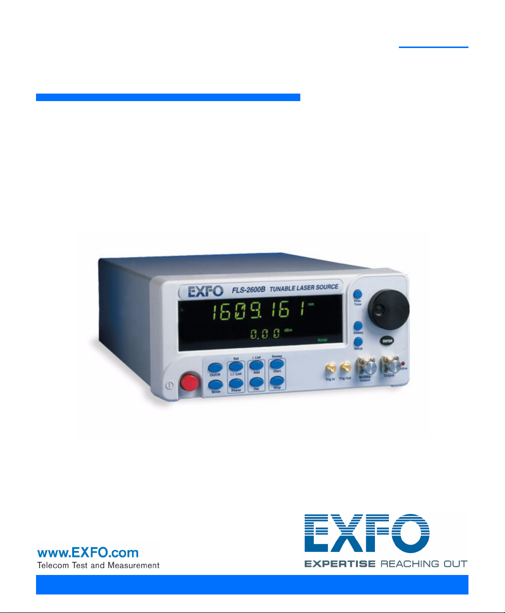
1 Introducing the FLS-2600B
FLS-2600B TUNABLE LASER SOURCE
Power
on/off
On/Off
Mode
/List
Power
List
Add
Del.
Set Sweep
Start
Stop
Trig In Trig Out Monitor
Output
Output
Setup
Sweep
Fine
tune
ENTER
Display
Source
on/off
Power
control
Access to Sweep menu
Monitor output
port
Add to
List
button
Switches between
and
List
Fine-Tuning button
Sweep Start
button
Trigger Out
SMA connector
Sweep Stop
button
Trigger In SMA
connector
Main output
port
Delete from List
button
Access to Setup menu
Switches between Normal and
High-Resolution modes
Selection
dial
Active LED
Enter
button
Tunable Laser Source
General Information
The FLS-2600B Tunable Laser Source addresses the testing requirements
for dense WDM component testing in the C- and L-bands.
Tunable Laser Source 1
Page 10
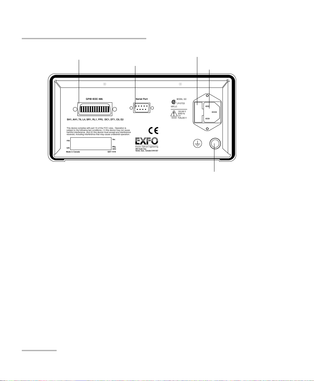
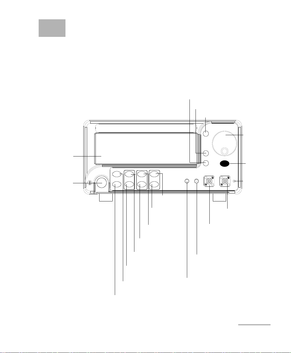
Introducing the FLS-2600B Tunable Laser Source
GPIB port Serial port
(RS-232 DTE)
Fuse holder
Power inlet
2
Ground
General Information
2 FLS-2600B
Page 11
Introducing the FLS-2600B Tunable Laser Source
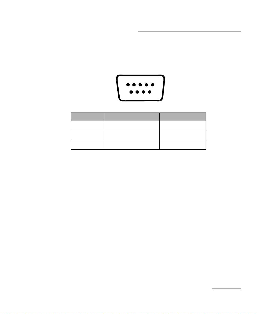
1234 5
6789
RS-232 Connector Pinout
RS-232 Connector Pinout
The RS-232 connector (serial port) at the back of the FLS-2600B uses a DTE
pinout configuration.
Pin Description Direction
2Receive (Rc) Input
3Transmit (Tx)Output
5 Signal ground (Gnd) —
The source has a medium coherence length that avoids problems such as
connector-induced interference and it is relatively immune to vibration. Its
linewidth is made up of several longitudinal modes that are present
simultaneously, resulting in no mode-hop-related measurement problems.
It also features a high-accuracy encoder for consistency in your results.
Tunable Laser Source 3
Your module may also feature the possibility to enable or disable the
automatic level control (ALC).
The FLS-2600B Tunable Laser Source supports local control (via its front
panel) and remote control (through GPIB or RS-232 using SCPI commands
or the provided LabVIEW drivers).
Page 12

Introducing the FLS-2600B Tunable Laser Source
Typic a l Ap pl ic ation s
Typical Applications
You can use your tunable laser source to perform several tasks, such as the
following:
characterizing filters, multiplexers, Bragg gratings, and other DWDM
components
checking wavelength-dependent gain, noise contribution and
saturation properties
determining the spectral sensitivity of receivers and detectors
performing high-loss tests on passive components
4 FLS-2600B
Page 13
Introducing the FLS-2600B Tunable Laser Source
Conventions
Conventions
Before using the product described in this manual, you should understand
the following conventions:
WARNING
Indicates a potentially hazardous situation which, if not avoided,
could result in death or serious injury. Do not proceed unless you
understand and meet the required conditions.
CAUTION
Indicates a potentially hazardous situation which, if not avoided,
may result in minor or moderate injury. Do not proceed unless you
understand and meet the required conditions.
CAUTION
Indicates a potentially hazardous situation which, if not avoided,
may result in component damage. Do not proceed unless you
understand and meet the required conditions.
IMPORTANT
Refers to information about this product you should not overlook.
Tunable Laser Source 5
Page 14

Page 15
2 Safety Information
Laser Safety Information
While handling optical fibers, laser radiation may be encountered at
source output ports and fiber ends. Avoid long-term exposure to laser
radiation.
WARNING
Do not install or terminate fibers while a light source is active.
Never look directly into a live fiber and ensure that your eyes are
protected at all times.
WARNING
Use of controls, adjustments and procedures for operation and
maintenance other than those specified herein may result in
hazardous radiation exposure or impair the protection provided by
this unit.
Your instrument is a Class 1M laser product in compliance with standards
IEC 60825-1 and 21 CFR 1040.10. Invisible laser radiation may be
encountered at the output port.
The product is safe under reasonably foreseeable conditions of operation
but it may be hazardous if you use optics within a diverging or collimated
beam. Do not view directly with optical instruments.
Tunable Laser Source 7
Page 16

Safety Information
Electrical Safety Information
Electrical Safety Information
The following safety precautions must be observed while operating and
servicing the unit. Failure to comply with these precautions or with specific
indications elsewhere in this manual violates safety standards of intended
use of the unit. EXFO assumes no liability for the user’s failure to comply
with these requirements.
This unit is intended for indoor use only.
Only fuses with the required rated current and specified type (IEC,
250 V, 2 A, fast blow, 0.197 in x 0.787 in/5 mm x 20 mm) may be used
for replacement. Do not use repaired fuses or short-circuited fuse
holders.
The power cable of the FLS-2600B Tunable Laser Source is the most
effective method to turn off the unit if a problem should occur.
Capacitors inside the unit may be charged, even if the unit has been
disconnected from its electrical supply.
Before turning on the unit, all grounding terminals, extensions cords,
and devices connected to it should also be connected to a protective
ground via a ground socket. Any interruption of the protective
grounding is a potential shock hazard and may cause personal injury.
Whenever the ground protection is impaired, the unit is not to be used,
and must be secured against any accidental or unintended operation.
Unit covers cannot be removed during operation.
Any adjustments, maintenance, and repair of opened units under
voltage should be avoided and carried out only by skilled personnel
aware of the hazards involved. Do not attempt internal service or
adjustment unless a person qualified to perform first aid is present.
Do not replace any components while power cable is connected.
8 FLS-2600B
Page 17

Safety Information
Electrical Safety Information
The unit must be positioned so as not to block the ventilation holes
located on each side of the unit and to allow easy disconnection of the
power cord if any problem should occur.
Operation of any electrical instrument around flammable gases or
fumes constitutes a major safety hazard.
Power Cable
This unit uses a three-wire power cable, which complies with international
safety standards. This cable serves as a ground when connected to an
appropriate AC power receptacle. The type of power cable supplied with
each unit is determined according to the country of destination.
Only qualified electricians should connect a new plug if needed. The color
coding used in the electrical cable depends on the cable. New plugs
should meet the local safety requirements and include the following
features:
adequate load-carrying capacity
ground connection
cable clamp
Tunable Laser Source 9
Page 18
Safety Information
Electrical Safety Information
To avoid electrical shock, do not operate the unit if there are signs
of damage to any part of the outer surface (covers, panels, etc.).
To avoid serious injury, you must observe the following precautions
before turning on the unit.
If the unit is to be powered via an auto-transformer for voltage
reduction, the common terminal must be connected to the
grounded power-source pole.
Insert the plug into a power outlet with a protective ground
contact. Do not use an extension cord without a protective
conductor.
Before turning on the unit, you must connect the protective
ground terminal of the unit to a protective conductor using the
unit power cord.
Do not tamper with the protective ground terminal.
WARNING
Equipment Ratings
Relative humidity 0 % to 80 % non-condensing
a
Maximum operation altitude 2000 m (6150 ft)
Pollution degree 2
Overvoltage category II
Power su p p ly ra ti ng
b
100 V to 240 V (50 Hz/60 Hz)
maximum 2 A
a. Measured in 0 °C to 31 °C (32 °F to 87.8 °F) range decreasing linearly to 50 % at 40 °C
(104 °F).
b. Not exceeding ± 10 % of the nominal voltage.
10 FLS-2600B
Page 19

3 Getting Started with Your
Tunable Laser Source
Turning on the Unit
Before turning on the FLS-2600B, please read the Safety Information on
page 7.
To turn the unit on and off, use the red button in the lower left-hand corner
of the front panel. The source is not active upon startup. To activate it, see
Activating/Deactivating Light Emission on page 42.
Upon startup, the unit beeps twice, performs a self-test, and then enters the
main menu with the same settings that were active when it was shut
down. When the unit is turned off, the following items remain in a storage
device called non-volatile memory:
current power setting
current wavelength setting
current mode (normal/high resolution)
current display mode (wavelength/power)
current Setup menu settings
shortlisted wavelengths (up to 100)
sweep parameters
saved sweep configurations (up to five)
Note: The power cord is the most effective disconnecting device. To ensure that
the unit is completely turned off, disconnect the power cord.
Tunable Laser Source 11
Page 20
Getting Started with Your Tunable Laser Source
DURATION
Sweep
Setup
START
STOP
MODE
STEP PAUSE
CYCLE REVERSE TRIGGER
UNIT REMOTE
DEVICE
DIMMER
SAVE RECALL
SPEED
BAUD
FLOW
ADJUST
SOUND
Turning on the Unit
Some internal mechanisms can sometimes take several seconds to adjust,
depending on the operation.
The front panel control provides access to the following options:
source activation/deactivation
Normal or High-Resolution mode
wavelength editing
shortlisted wavelengths
power editing
shortlisted wavelength addition or deletion
start and stop sweep
The blue buttons to the right of the display give access to single-level
menus: Sweep and Setup. Unless a sweep is under way, these menus can
always be accessed, even while the source is active. The following
diagram shows these two menus and their items.
To move between the menu items, turn the selection dial. To exit a menu,
press the button that gave access to it (Sweep or Setup). The FLS-2600B
will return to its previous state.
Note: The unit will beep whenever the FLS-2600B does not allow an operation.
12 FLS-2600B
Page 21

Getting Started with Your Tunable Laser Source
Pos ition ing Your U nit Using the Support Stands
Positioning Your Unit Using the Support
Stands
To change the orientation of your unit, you can use the support stands
located on the bottom front part of the casing. Simply pull them down until
they lock into place.
Tunable Laser Source 13
Page 22

Page 23

4 Setting Standard Parameters
Edit
Setting the Display Intensity
You might want to set the display intensity of your unit, or turn the
display off.
To change the display intensity:
1. Press Setup.
2. Turn the selection dial clockwise until DIMMER is displayed.
The current dimmer status appears.
3. Press ENTER. The Edit marker starts blinking in the lower part of the
display.
4. Turn the selection dial until you see the desired display intensity (LO,
HI, OFF, or Auto. OFF), then press ENTER.
Setting the dimmer to OFF turns off the display. Press any key to turn the
display back on.
Setting the dimmer to Auto. OFF also turns off the display. Press any key to
turn the display back on. However, after five seconds, the display will
automatically turn off again.
5. To e x i t the Setup menu, press Setup.
Tunable Laser Source 15
Page 24
Setting Standard Parameters
Edit
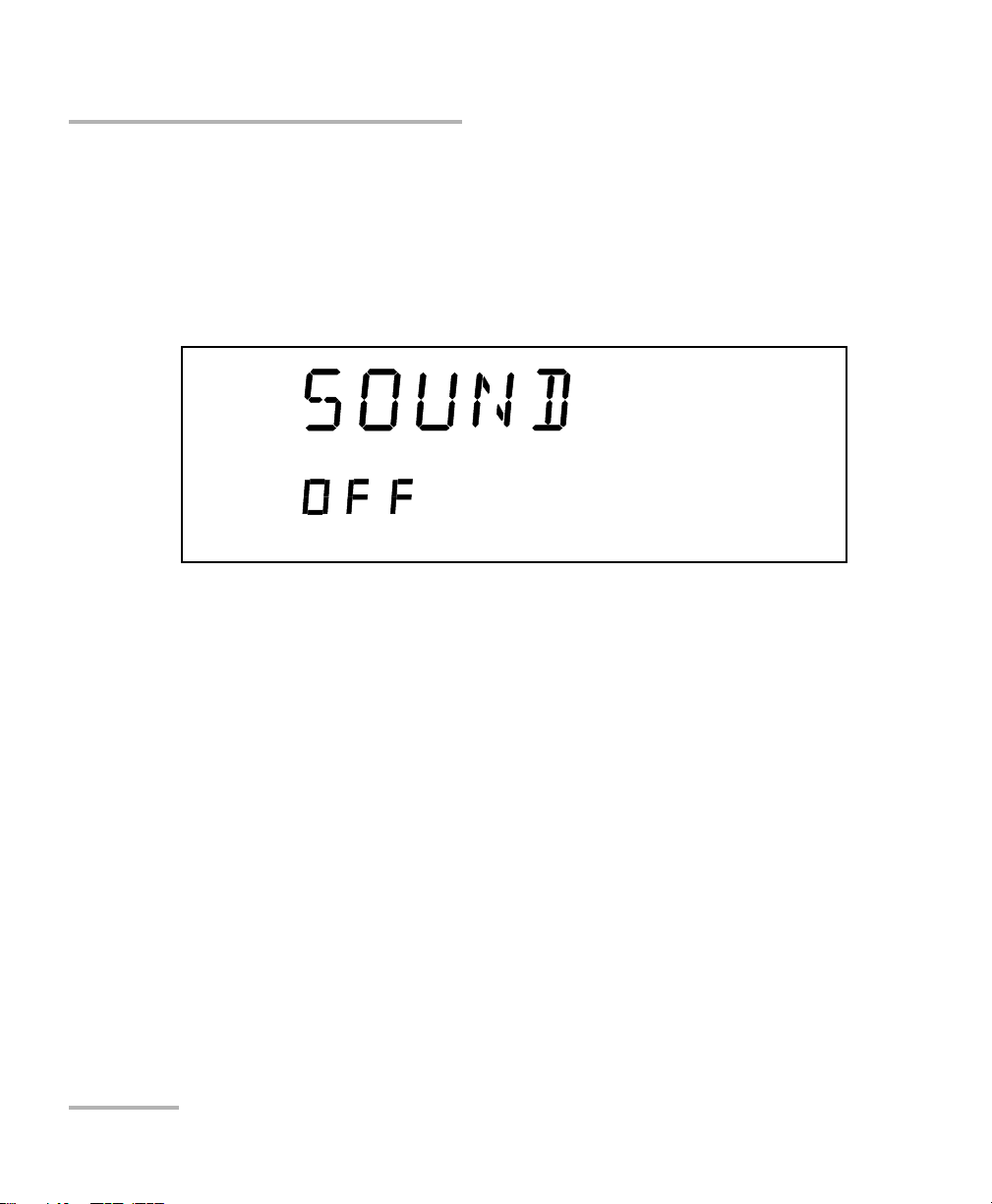
Turning the Sound On or Off
Turning the Sound On or Off
To turn the sound on your unit on or off:
1. Press Setup.
2. Turn the selection dial clockwise until SOUND is displayed. The current
sound status appears.
3. Press ENTER. The Edit marker starts blinking in the lower part of the
display.
4. Turn the selection dial until you reach the state you want (on or off),
then press ENTER.
To exi t the Setup menu, press Setup.
16 FLS-2600B
Page 25

Setting Standard Parameters
Switching between Normal and High-Resolution (HR) Modes
Switching between Normal and
High-Resolution (HR) Modes
In HR mode, the laser linewidth is reduced by a factor of 20 %. Typically, at
1550 nm, the Normal mode will produce a 1.6 GHz FWHM linewidth, while
the HR mode will produce a 1.4 GHz FWHM linewith. The tuning range
(or power at extreme wavelength) might be smaller in HR mode than in
Normal mode.
To select the operation mode:
Press the mode control button on the front panel.
Adjusting Decimals Using the Fine-Tune Feature
You can select values for your testing needs in two different ways:
Fine-tune and Coarse. If you press the Fine-tune button on the front panel,
Fine-tune appears on the display and you will be able to set the decimals.
If Fine-tune does not appear on the display, you are in Coarse mode and
can only adjust the numbers before the decimal point with the
selection dial.
Note: The Fine-tune feature applies to every numerical edition function with a
decimal point except in the Adjust submenu of the Setup menu.
See Adjusting Your Unit According to Wavelength on page 54 for more
information.
Tunable Laser Source 17
Page 26

Setting Standard Parameters
Selecting the Display Unit
Selecting the Display Unit
It is possible to select the display unit with which you want to work.
To select the display unit:
1. Press Setup.
2. The menu displays UNIT right away. Press ENTER to edit the units.
3. Turn the selection dial clockwise or counterclockwise to select the
desired unit (nm or THz).
4. Press ENTER to validate your choice and Setup to exit the Setup menu.
The selection affects all relevant wavelength settings, including those in the
Sweep.
18 FLS-2600B
Page 27
Setting Standard Parameters
Normal
nm
Fine-tune
dBm
Selecting a Wavelength
Selecting a Wavelength
There are several ways to select a wavelength for testing.
Entering a Wavelength Directly
To select a wavelength, make sure you are in Wavelength Edition mode.
To se l ect t h e Wavelength Edition mode, press the
front panel, so that
appears on the upper left-hand corner of the display.
/
List button on the
To select a specific wavelength, turn the selection dial clockwise or
counterclockwise until you reach the desired wavelength. The module will
then set the wavelength according to your selection.
If the set power cannot be maintained at the selected wavelength
(especially at extreme wavelengths), the displayed power value will flash,
a message appears in the status bar, and the power is no longer in constant
power mode. The output power stability and level will be the natural laser
emission.
To stop the power display from flashing and have the power regulation
work again, set the wavelength at an interval where the displayed power
can be reached, or decrease the power.
Tunable Laser Source 19
Page 28
Setting Standard Parameters
Normal
nm
list
Selecting a Wavelength
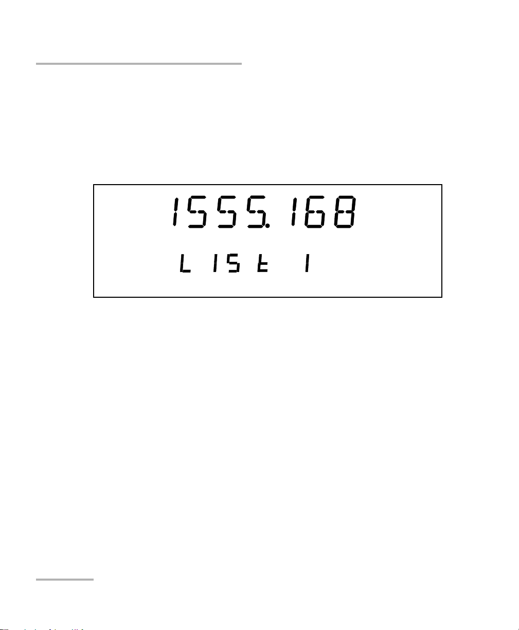
Retrieving a Wavelength from a Stored List
To select a wavelength from the list of wavelengths already
saved in the internal memory:
1. Ensure that you are in Wavelength List Edition mode. To select this
mode, press the
appears on the upper left-hand corner of the display.
2. Turn the selection dial clockwise or counterclockwise until you reach
the desired listed wavelength.
/
List button on the front panel so thatList
The list number corresponding to your wavelength selection will appear for
a few seconds, then the current power setting will reappear.
To add a wavelength to the list, see Adding Items to Lists on page 22.
20 FLS-2600B
Page 29
Setting Standard Parameters
Normal
nm
Fine-tune
Power
dBm
Setting the Power
Setting the Power
To set the output power, you must be in Power Edition mode. To select the
Power Edition mode, press the Power button on the front panel, so that
Power appears in the left part of the display.
To select a specific power value, turn the selection dial clockwise or
counterclockwise until you reach the desired power value. The source will
then send the command to set the power according to your selection.
Note: If the set power cannot be maintained at the selected wavelength
(especially at extreme wavelengths), the displayed power value will flash
and you will no longer be in Constant Power mode. The output power
stability and level will be the natural laser emission. To stop the power
display from flashing and have the power regulation work again, set the
wavelengths at an interval where the displayed power can be reached or
select a lower power for your wavelength. For more information on how to
set a specific wavelength, see Entering a Wavelength Directly on page 19.
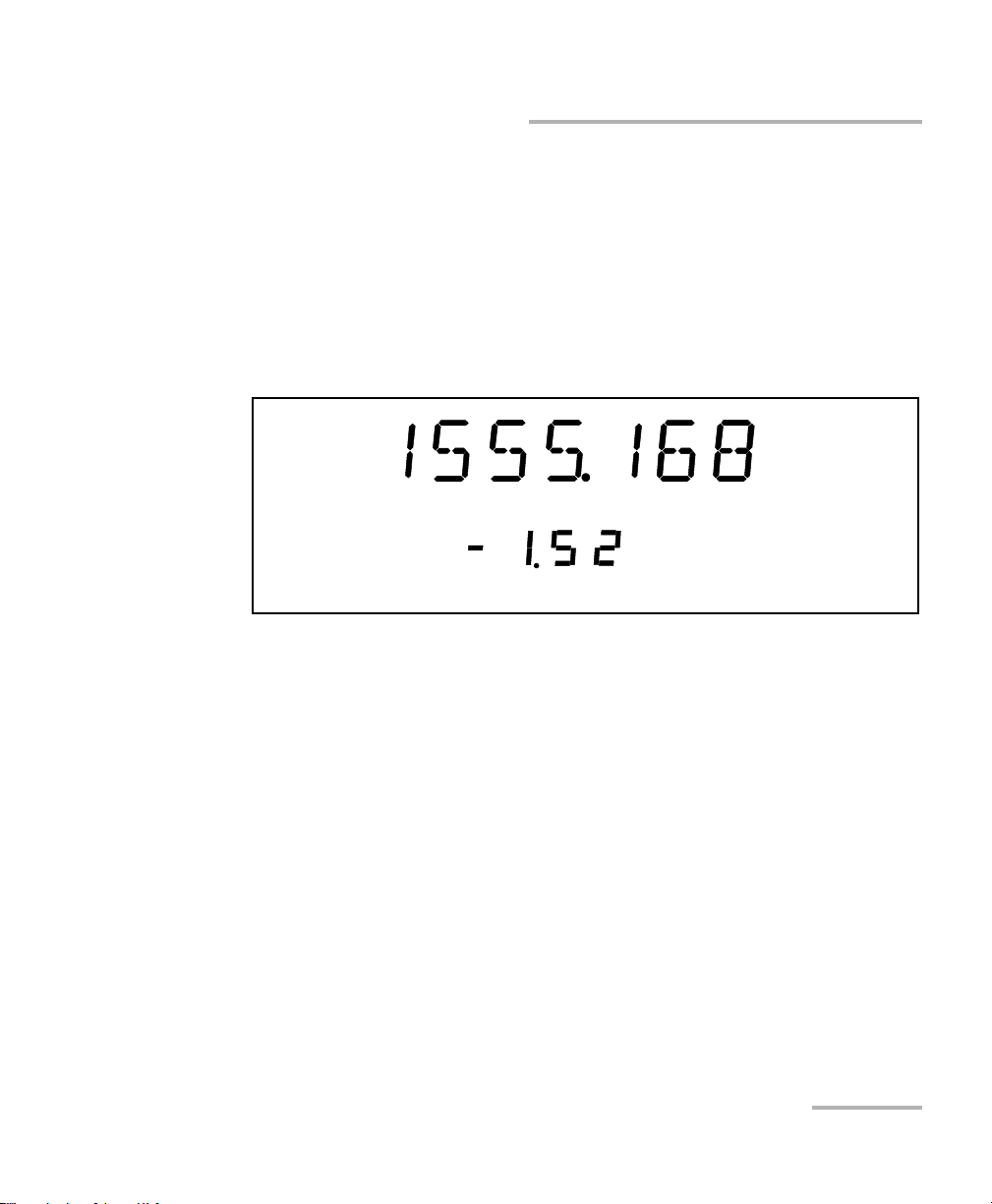
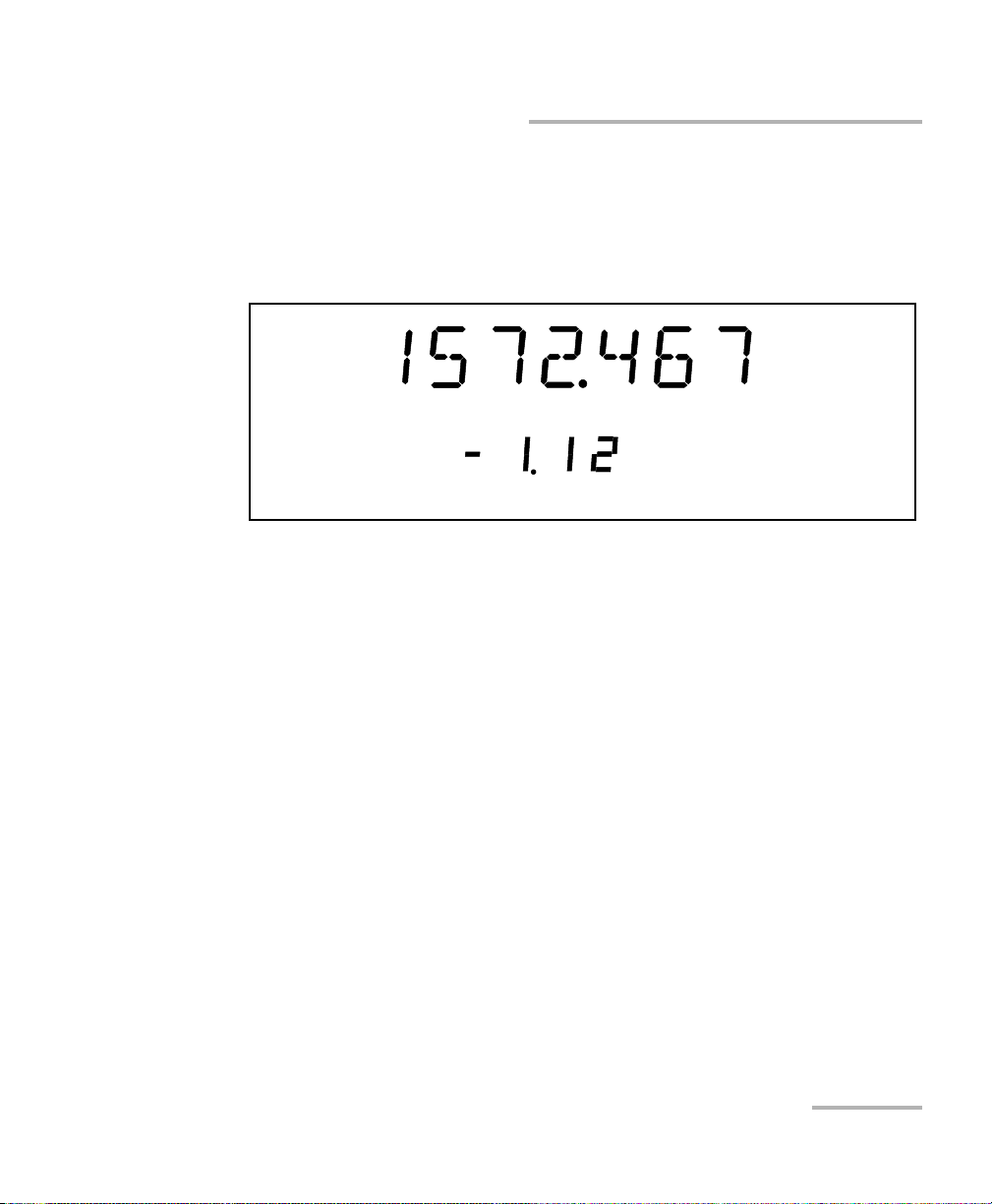
Your source can either be in Normal Power mode (where the ALC is
enabled), or in Max. Power mode (where the ALC is disabled).
To ch a nge t h e Automatic Level Control status, press on the Power/Pmax.
button. If you see Power on the left side of the display, you are in Normal
Pow er mode. If you see Max. Power on the right side of the display, you are
in Max. Power mode. Once you have selected Max. Power, the unit reverts
to or List mode, according to the one you used last.
Tunable Laser Source 21
Page 30

Setting Standard Parameters
Adding Items to Lists
Adding Items to Lists
You can add items to the current list of wavelengths.
To add items:
1. Make sure you are in Wavelength Edition mode (
the Wavelength Edition mode, see Selecting a Wavelength on page 19.
2. Turn the selection dial clockwise or counterclockwise until you reach
the desired wavelength.
3. Press the Add button on the front panel.
mode). To select
To indicate that the new wavelength was saved, a number between
1 and 100, stating the wavelength’s rank in the list, as well as the
ADD mention, will appear. If the list is full, the display will indicate FULL,
and you will hear a beep. You will need to delete some wavelengths before
adding more to the list.
The new wavelength is always added to the end of the list, regardless of its
value, using the next available list number. This means that your entries will
not be in ascending or descending numerical order if not entered as such.
To create an ascending list of wavelengths, enter your values beginning
with the lowest and finishing with the highest. To create a descending list
of wavelengths, simply enter your values from highest to lowest.
22 FLS-2600B
Page 31

Setting Standard Parameters
Deleting Items from Lists
Deleting Items from Lists
You can delete items from the current list of wavelengths.
To d el e te it e ms :
1. Make sure you are in Wavelength List Edition mode (
To se l ect t h e Wavelength List Edition mode, see Retrieving a
Wavelength from a Stored List on page 20.
2. Turn the selection dial clockwise or counterclockwise until you reach
the desired listed wavelength.
3. Press the Del button on the front panel.
List mode).
To indicate that the wavelength was deleted, a number between 1 and 100,
stating the wavelength’s rank in the list, as well as the DEL
appear. If the list is empty, the display will indicate EMPTY, and you will
hear a beep.
Note: Deleting a wavelength will shift the ranking of the other entries.
For example, if you delete entry number 3 in a list of five items, number 4
will become 3 and number 5 will become 4.
Tunable Laser Source 23
mention will
Page 32

Setting Standard Parameters
Using the Monitor Output
Using the Monitor Output
The monitor output of the FLS-2600B, located on the front of the unit, is
mainly used to monitor the wavelength of the emitted signal with a
wavelength meter. The power available through the monitor corresponds
to approximately 10 % of the total power output, even though neither this
fraction nor the power stability emitted are guaranteed.
You cannot deactivate the monitor output.
IMPORTANT
24 FLS-2600B
Page 33

Setting Standard Parameters
Saving and Recalling Configurations
Saving and Recalling Configurations
Once you have set the FLS-2600B Tunable Laser Source parameters, you
can save your custom configuration and recall it at any time. You can also
recall the factory-defined settings.
Note: You can save or recall up to five configurations.
Saved parameters are
Start wavelength of the sweep
End wavelength of the sweep
Number of sweeps (1-99 or loop)
Sweep speed (Continuous mode)
Sweep duration (Continuous mode)
Step size (Step-by-Step mode)
Pause length (Step-by-Step mode)
Reverse status (ON/OFF)
Trigger status (ON/OFF)
Tunable Laser Source 25
Page 34

Setting Standard Parameters
Edit
Edit
Saving and Recalling Configurations
To save or recall a sweep configuration:
1. Press Sweep.
2. Turn the selection dial clockwise until SAVE or RECALL is displayed,
depending on the action you want to perform.
3. Press ENTER. The Edit marker starts blinking in the lower left-hand
corner of the display.
4. Turn the selection dial clockwise or counterclockwise to select the
desired number where you want to save your configuration.
5. Press ENTER to validate your choice, and Sweep to exit the Sweep
menu.
26 FLS-2600B
Page 35

Setting Standard Parameters
Reverting to Factory Settings
Reverting to Factory Settings
Turning on the unit and pressing ENTER at the same time until it beeps
three times will reset the unit to the following default values:
Parameters Reset Value or State
Edit mode (/ list)|(Power)
Source mode (Normal|HR) Normal
Lambda unit (nm|THz) nm
Fine-tune (Active|Inactive) Active
Lambda 1550.000 nm
Power 0.0 d Bm
Lambda list Empty
Lambda list index (0-100) 1
Sweep program (1-5) 1
Dimmer status (Hi, Low, Off, Auto. Off) Hi
Key sound (On|Off) Off
Sweep range 1540.000 nm to 1560.000 nm
Sweep mode Continuous
Speed 10.000 nm/s
Step 10.000 nm
Pause 1000 ms (1 second)
Cycles (1-99 or Loop) Loop
Reverse (Active|Inactive) Inactive
Trigger (Active|Inactive) Inactive
GPIB Address
RS-232/GPIB
a. This setting will only change with a local reset.
Tunable Laser Source 27
a
a
12
GPIB
Page 36

Page 37

5 Setting Sweep Parameters
Fine-tune
Edit
nm
Your tunable laser source allows you to perform automatic wavelength
scans according to user-defined parameters. You can perform a
continuous sweep (the source will make one or several continuous
passes), or you can perform a step-by-step sweep (the signal wavelength
changes according to preset increments or steps).
Setting the Start and End Wavelengths
The wavelength scans and their lengths (or duration) depend on the start
and end wavelengths you set.
To set the wavelengths for your scans:
1. Press Sweep. You will be in the START
menu.
2. Press ENTER. The Edit marker starts blinking in the lower part of the
display.
3. Tu r n t h e se l e cti o n dia l clockwise or counterclockwise until the desired
wavelength is displayed.
4. Press ENTER. You can select a wavelength at a resolution of 0.001 nm.
5. To e x i t the Sweep menu, press Sweep.
OR
Tunable Laser Source 29
Turn the dial clockwise or counterclockwise until EXIT is displayed,
then press ENTER.
Page 38

Setting Sweep Parameters
Edit
Selecting the Sweep Mode
To set the end wavelength, repeat the process, but after pressing on
Sweep, turn the selection dial clockwise until
Note: The start and end wavelengths of the sweep can be set in ascending or
descending order, with a minimum value of 1.0 nm. The sweep will be
performed accordingly.
STOP is displayed.
Selecting the Sweep Mode
You can select the sweep mode you want to perform in the Sweep menu.
The source will use either the Continuous or Stepped mode.
To set the sweep mode you want to use:
1. Press Sweep.
2. Turn the selection dial clockwise until
3. Press ENTER. The Edit marker starts blinking in the bottom left-hand
corner of the display.
4. Turn the selection dial clockwise or counterclockwise until the desired
mode is displayed: Continuous (Cont.) or Step-by-Step (Step).
5. Press ENTER to confirm your choice, and then Sweep to exit the
Sweep menu.
The sweeps will now be performed according to the mode you have
selected.
MODE is displayed.
30 FLS-2600B
Page 39

Setting Sweep Parameters
Edit
nm
Setting the Sweep Step
Setting the Sweep Step
You can set the size of the step (in nm or THz) for your step-by-step sweep.
Your tunable laser source unit was designed to give a constant step value
using nm as units. When steps are given in THz, the selected step value
represents the average value of the steps during the sweep, since an
interval in nm does not always have the save equivalent value in THz
according to the wavelength bandwidth you have selected.
To set the step:
1. Make sure you have selected the step-by-step sweeping mode (as seen
in Selecting the Sweep Mode on page 30).
2. Press Sweep.
3. Turn the selection dial clockwise until STEP is displayed.
4. Press ENTER. The Edit marker starts blinking in the lower part of the
display.
5. Turn the selection dial clockwise or counterclockwise to select the
desired size for the step.
Tunable Laser Source 31
Page 40

Setting Sweep Parameters
Setting the Pauses
6. Press ENTER to validate your choice, and Sweep to exit the menu.
OR
Turn the dial clockwise or counterclockwise until EXIT is displayed,
then press ENTER.
Note: If the sweep wavelength range is not a multiple of the step value selected,
the stop wavelength will be truncated to the nearest possible value, thus
reducing the range.
Setting the Pauses
You can set a time interval or pauses between steps. First, make sure you
have selected the Step-by-Step sweep mode. For more information, see
Selecting the Sweep Mode on page 30.
To set the length of the pauses between the steps:
1. Press Sweep.
2. Turn the selection dial clockwise until PAUSE is displayed.
3. Press ENTER. The Edit marker starts blinking in bottom left-hand
corner of the display.
32 FLS-2600B
Page 41

Setting Sweep Parameters
Fine-tune
Edit
m/s/ms
Setting the Sweep Speed
4. Turn the selection dial clockwise or counterclockwise to select the
desired length of time for the pause. The pause range goes from
0.050 to 60.000 seconds.
5. Press ENTER to validate your choice, and Sweep to exit the Sweep
menu.
Setting the Sweep Speed
You can change the sweep speed when you are in Continuous mode.
For more information on setting the mode to Continuous, see Selecting the
Sweep Mode on page 30.
To change the speed:
1. Press Sweep.
2. Turn the selection dial clockwise until SPEED is displayed.
3. Press ENTER. The Edit marker starts blinking in the bottom left-hand
corner of the display.
Tunable Laser Source 33
Page 42

Setting Sweep Parameters
Fine-tune
Edit nm/s
Setting the Sweep Speed
4. Turn the selection dial clockwise or counterclockwise to select the
desired speed of the sweep.
.
5. Press ENTER to validate your choice, and Sweep to exit the Sweep
menu.
Note: Setting the speed will automatically determine the duration of one pass
according to the selected range.
Your FLS-2600B unit was designed to give a constant speed value using nm
as units. When the speed is given in a THz environment, the selected
speed value represents the average value during the sweep, since an
interval in nm does not always have the same equivalent value in THz
according to the wavelength bandwidth you have selected.
Note: You cannot edit the duration of the scan. It will be automatically calculated
according to the speed and wavelength range.
To add or delete steps from the lists, see Adding Items to Lists on page 22
and Deleting Items from Lists on page 23.
34 FLS-2600B
Page 43

Setting Sweep Parameters
Edit
Selecting the Incoming Trigger Option
Selecting the Incoming Trigger Option
The incoming trigger option allows you to synchronize your sweeps with
signals from other units.
To switch the incoming trigger option on or off:
1. Press Sweep.
2. Turn the selection dial clockwise until TRIGGER is displayed.
3. Press ENTER. The Edit marker starts blinking in the lower part of the
display.
4. Turn the selection dial clockwise or counterclockwise to turn the
Trigger option on or off.
5. Press ENTER to validate your choice and Sweep to exit the Sweep
menu.
For more information about the trigger option on your tunable laser source,
see Trigger Option Theory on page 69.
Tunable Laser Source 35
Page 44

Setting Sweep Parameters
Edit
Setting the Cycle Options
Setting the Cycle Options
The cycle options allow you to specify settings in both continuous and
stepped sweep modes.
You can set a specific number of cycles for the sweep to perform.
To set the number of cycles:
1. Press Sweep.
2. Turn the selection dial clockwise until CYCLES is displayed.
3. Press ENTER. The Edit marker starts blinking in the bottom left-hand
corner of the display.
4. Turn the selection dial clockwise or counterclockwise to select the
desired number of sweep cycles. You can select a number from
1 to 99. You can also select Continuous cycling by turning the selection
dial counterclockwise until you pass 1. The display will then indicate
Loop.
5. Press ENTER to validate your choice, and Sweep to exit the Sweep
menu.
36 FLS-2600B
Page 45

Setting Sweep Parameters
Edit
Setting the Sweep Direction
Setting the Sweep Direction
The sweep can be either unidirectional, meaning that it will only go in one
direction, or bidirectional, sweeping back and forth. This is set through the
Reverse feature of your FLS-2600B.
To set the direction of the sweep:
1. Press Sweep.
2. Turn the selection dial clockwise until REVERSE is displayed.
3. Press ENTER. The Edit marker starts blinking in the bottom left-hand
corner of the display.
4. Turn the selection dial clockwise or counterclockwise to turn the
Reverse option on or off.
5. Press ENTER to validate your choice, and Sweep to exit the Sweep
menu.
Tunable Laser Source 37
Page 46

Page 47

6 Operating your Tunable Laser
Source
Cleaning and Connecting Optical Fibers
IMPORTANT
To ensure maximum power and to avoid erroneous readings:
Always inspect fiber ends and make sure that they are clean as
explained below before inserting them into the port. EXFO is
not responsible for damage or errors caused by bad fiber
cleaning or handling.
Ensure that your patchcord has appropriate connectors. Joining
mismatched connectors will damage the ferrules.
To connect the fiber-optic cable to the port:
1. Inspect the fiber using a fiber inspection microscope. If the fiber is
clean, proceed to connecting it to the port. If the fiber is dirty, clean it as
explained below.
2. Clean the fiber ends as follows:
2a. Gently wipe the fiber end with a lint-free swab dipped in isopropyl
alcohol.
2b. Use compressed air to dry completely.
2c. Visually inspect the fiber end to ensure its cleanliness.
Tunable Laser Source 39
Page 48

Operating your Tunable Laser Source
Cleaning and Connecting Optical Fibers
3. Carefully align the connector and port to prevent the fiber end from
touching the outside of the port or rubbing against other surfaces.
If your connector features a key, ensure that it is fully fitted into the
port’s corresponding notch.
4. Push the connector in so that the fiber-optic cable is firmly in place,
thus ensuring adequate contact.
If your connector features a screwsleeve, tighten the connector
enough to firmly maintain the fiber in place. Do not overtighten, as this
will damage the fiber and the port.
Note: If your fiber-optic cable is not properly aligned and/or connected, you will
notice heavy loss and reflection.
40 FLS-2600B
Page 49

Operating your Tunable Laser Source
Bare metal
(or blue border)
indicates UPC
option
Green border
indicates APC
option
2 3 4
Installing the EXFO Universal Interface (EUI)
Installing the EXFO Universal Interface (EUI)
The EUI fixed baseplate is available for connectors with angled (APC) or
non-angled (UPC) polishing. A green border around the baseplate
indicates that it is for APC-type connectors.
To install an EUI connector adapter onto the EUI baseplate:
1. Hold the EUI connector adapter so the dust cap opens downwards.
2. Close the dust cap in order to hold the connector adapter more firmly.
3. Insert the connector adapter into the baseplate.
4. While pushing firmly, turn the connector adapter clockwise on the
baseplate to lock it in place.
Tunable Laser Source 41
Page 50

Operating your Tunable Laser Source
Activating/Deactivating Light Emission
Activating/Deactivating Light Emission
Before turning on the Tunable Laser Source, please read the Safety
Information on page 7.
If the source has been exposed to extreme conditions or if you feel that a
calibration would help you achieve better results, you can perform an
offset calibration as described in Adjusting Your Unit According to
Wavelength on page 54.
To activate or deactivate the light emission:
1. Press the On/Off button. The Source init. marker appears on the
display.
2. The Active LED lights up on the module front panel to indicate that the
source is active at the wavelength, output power, and mode currently
selected.
3. To deactivate the source, press On/Off again.
The Active LED usually lights up immediately, but the laser power is
ramped to its maximum in about five seconds. If an error occured
with the power prior to the source initialization, the active LED can
take up to three seconds to light up.
IMPORTANT
IMPORTANT
To obtain optimum stability, a laser source should be allowed to
warm up for 60 minutes.
42 FLS-2600B
Page 51

Operating your Tunable Laser Source
Starting a Sweep
Starting a Sweep
After setting your sweep parameters as explained in Setting Sweep
Parameters on page 29 and that your source is turned on, you are ready to
start your sweep.
To start the sweep, press the Start button on the front panel. The system
will perform the sweep according to the settings you have entered.
To stop the sweep before it is completed, press the Stop button on the
front panel.
Note: You can stop the sweep at any time. Turning the laser on or off will also
stop the sweep.
Tunable Laser Source 43
Page 52

Page 53

7 Maintenance
To help ensure long, trouble-free operation:
Always inspect fiber-optic connectors before using them and clean
them if necessary.
Keep the unit free of dust.
Clean the unit casing and front panel with a cloth slightly dampened
with water.
Store unit at room temperature in a clean and dry area. Keep the unit
out of direct sunlight.
Avoid high humidity or significant temperature fluctuations.
Avoid unnecessary shocks and vibrations.
If any liquids are spilled on or into the unit, turn off the power
immediately, disconnect from any external power source, remove the
batteries and let the unit dry completely.
Use of controls, adjustments, and procedures for operation and
maintenance other than those specified herein may result in
hazardous radiation exposure.
WARNING
Tunable Laser Source 45
Page 54

Maintenance
Cleaning Fixed Connectors
Cleaning Fixed Connectors
Regular cleaning of connectors will help maintain optimum performance.
Do not try to disassemble the unit. Doing so would break the connector.
To clean fixed connectors:
1. Fold a lint-free wiping cloth in four to form a square.
2. Moisten the center of the lint-free wiping cloth with only one drop of
isopropyl alcohol.
Alcohol may leave traces if used abundantly. Avoid contact between
the tip of the bottle and the wiping cloth, and do not use bottles
that distribute too much alcohol at a time.
3. Gently wipe the connector threads three times with the folded and
moistened section of the wiping cloth.
IMPORTANT
IMPORTANT
Isopropyl alcohol takes approximately ten seconds to evaporate.
Since isopropyl alcohol is not absolutely pure, evaporation will
leave microscopic residue. Make sure you dry the surfaces before
evaporation occurs.
4. With a dry lint-free wiping cloth, gently wipe the same surfaces three
times with a rotating movement.
5. Throw out the wiping cloths after one use.
6. Moisten a cleaning tip (2.5 mm tip) with only one drop of isopropyl
alcohol.
46 FLS-2600B
Page 55

Maintenance
7
8
9
Cleaning Fixed Connectors
IMPORTANT
Alcohol may leave traces if used abundantly. Avoid contact between
the tip of the bottle and the cleaning tip, and do not use bottles
that distribute too much alcohol at a time.
7. Slowly insert the cleaning tip into the connector until it reaches the
ferrule inside (a slow clockwise rotating movement may help).
8. Gently turn the cleaning tip one full turn.
9. Continue to turn as you withdraw the cleaning tip.
10. Repeat steps 7 to 9, but this time with a dry cleaning tip (2.5 mm tip
provided by EXFO).
Note: Make sure you don’t touch the soft end of the cleaning tip and verify the
cleanliness of the cotton tip.
11. Throw out the cleaning tips after one use.
Tunable Laser Source 47
Page 56

Maintenance
Push
Tur n
Pull
3
4
5
Cleaning EUI Connectors
Cleaning EUI Connectors
Regular cleaning of EUI connectors will help maintain optimum
performance. There is no need to disassemble the unit.
If any damage occurs to internal connectors, the module casing will
have to be opened and a new calibration will be required.
To clean EUI connectors:
1. Remove the EUI from the instrument to expose the connector
baseplate and ferrule.
IMPORTANT
2. Moisten a 2.5 mm cleaning tip with one drop of isopropyl alcohol
(alcohol may leave traces if used abundantly).
3. Slowly insert the cleaning tip into the EUI adapter until it comes out on
the other side (a slow clockwise rotating movement may help).
4. Gently turn the cleaning tip one full turn, then continue to turn as you
withdraw it.
48 FLS-2600B
Page 57

Cleaning EUI Connectors
5. Repeat steps 3 to 4 with a dry cleaning tip.
Note: Make sure you don’t touch the soft end of the cleaning tip.
6. Clean the ferrule in the connector port as follows:
6a. Deposit one drop of isopropyl alcohol on a lint-free wiping cloth.
IMPORTANT
Isopropyl alcohol may leave residues if used abundantly or left to
evaporate (about 10 seconds).
Avoid contact between the tip of the bottle and the wiping cloth,
and dry the surface quickly.
6b. Gently wipe the connector and ferrule.
6c. With a dry lint-free wiping cloth, gently wipe the same surfaces to
ensure that the connector and ferrule are perfectly dry.
6d. Verify connector surface with a portable fiber-optic microscope
(for example, EXFO’s FOMS) or fiber inspection probe (for
example, EXFO’s FIP).
Maintenance
WARNING
Verifying the surface of the connector WHILE THE UNIT IS ACTIVE
WILL result in permanent eye damage.
7. Put the EUI back onto the instrument (push and turn clockwise).
8. Throw out cleaning tips and wiping cloths after one use.
Tunable Laser Source 49
Page 58

Maintenance
Replacing the Fuse
Replacing the Fuse
The FLS-2600B contains two fuses of type IEC, 250 V, 2 A, fast blow
0.197 in x 0.787 in/5 mm x 20 mm. The fuse holder is located at the back of
the FLS-2600B, just beside the power inlet.
To replace the fuses:
1. Unplug the power cord from the FLS-2600B.
2. Pull the fuse holder out of the FLS-2600B.
3. Check and replace the fuses if necessary.
Employer uniquement avec
Use only with a 250V fuse
un fusible de 250V
4. Make sure the fuses are placed firmly in the holder prior to its
reinsertion.
5. Firmly push the holder into place.
50 FLS-2600B
Page 59

Maintenance
Software Upgrades
Software Upgrades
To upgrade the FLS-2600B embedded software using a diskette, you must
connect your FLS-2600B to a computer through a null modem cable.
Note: Software upgrades may be performed in DOS, Windows 3.1, Windows 95,
Windows 98 or Windows 2000. If problems occur, please contact EXFO.
IMPORTANT
When using a notebook computer to upgrade the FLS-2600B
software, you should perform the upgrade in a DOS environment.
Proceed with the software upgrade only if the version indicated on
the diskette is greater than the software version currently installed
in your unit. To check the software version currently installed on
your unit, see the information displayed at startup.
Tunable Laser Source 51
Page 60

Maintenance
Software Upgrades
To perform a software upgrade:
1. Turn off the FLS-2600B.
2. If it is not already done, turn on the computer.
3. On the hard disk of your computer, create a directory named "Tes t"
4. Insert the upgrade diskette into the computer’s floppy disk drive and
5. Connect one end of a null modem cable to the FLS-2600B RS-232 serial
6. If the software upgrade is performed in Windows 98, you have to
(C:\Test).
copy the *.hex file into the new directory (if necessary, unzip the file).
port and the other end to an unused communication port on your
computer (ex. COM2).
restart your computer in DOS mode before starting the upgrade
program. Otherwise, simply exit to DOS.
From C:\Te st directory, type LO0006.exe /c:2 /F:C:\Test\*.hex,
which can be decoded as follows:
2 represents the serial port number. In this case, it means COM2.
There is a space between LO0006.exe and /.
There is a space between c:2 and /F.
* represents the name of the file. Do not type *.hex, but rather the
actual name of the file you copied to your hard disk.
7. Press Enter.
52 FLS-2600B
Page 61

Maintenance
Software Upgrades
8. When the Waiting for device handshake message appears, turn on the
FLS-2600B. The FLS-2600B screen will remain off; the unit will beep
once and the update program will start automatically. A progress bar
on the computer screen will indicate the status of the software
upgrade.
9. Once the software upgrade is complete, the Reboot device for self-test
message will appear. If the software upgrade was performed in
Windows 2000, the following error message will be displayed: LO0006
NTVDM has encountered a System Error. The parameter is incorrect.
Select “Close” to terminate the application. Click Close to hide the
dialog box.
10. You must turn the FLS-2600B off, and then on again, to use the
upgraded software. During self-test execution, the FLS-2600B should
display the new software version number.
Tunable Laser Source 53
Page 62

Maintenance
Edit
nm
Adjusting Your Unit According to Wavelength
Adjusting Your Unit According to Wavelength
It is possible to introduce an offset in your Tunable Laser Source to correct
a wavelength deviation as measured by a reference wavelength meter.
Note: A calibrated wavelength meter is required to perform a user calibration on
your unit.
To adjust your module at a certain wavelength:
1. Turn your Tunable Laser Source on.
2. Press Setup.
3. Turn the selection dial until ADJUST is displayed. The default
pre-selected wavelength appears.
4. Press ENTER. The Edit marker starts blinking in the lower part of the
display.
5. Connect your FLS-2600B to a calibrated wavelength meter.
6. Turn the selection dial until you reach the wavelength value read on
the wavelength meter, then press ENTER to validate it.
Note: The Fine-tune feature is not available in this submenu.
54 FLS-2600B
Page 63

Maintenance
Adjusting Your Unit According to Wavelength
7. To ex it th e Setup menu, press Setup.
Note: The difference between the pre-selected wavelength and the measured
wavelength cannot be greater than ± 0.200 nm or ± 0.0250 THz.
This user-performed calibration feature can help you achieve better
absolute wavelength accuracy if, for example, you feel that conditions
outside the unit may have affected the calibration.
The difference between the pre-selected wavelength and the measured
wavelength cannot be greater than ± 0.200 nm. If the difference between
the measured and preselected wavelengths is greater than ± 0.200 nm
(for example, if you have entered the wrong value), an error message will
be generated.
IMPORTANT
Note that the offset introduced into the Tunable Laser Source with
this software feature cannot be disabled. To correct for a handling
error during the procedure, you must repeat the steps described
above with a calibrated wavelength meter.
Tunable Laser Source 55
Page 64

Maintenance
Recalibrating the Unit
Recalibrating the Unit
Manufacturing and service center calibrations are based on the
ISO/IEC 17025 Standard, which states that calibration documents must not
contain a recommended calibration interval, unless this has been
previously agreed upon with the customer.
Validity of specifications depends on operating conditions. For example,
the calibration validity period can be longer or shorter depending on the
intensity of use, environmental conditions and unit maintenance. You
should determine the adequate calibration interval for your unit according
to your accuracy requirements.
Under normal use, EXFO recommends calibrating your unit every year.
Recycling and Disposal (Applies to European Union Only)
For complete recycling/disposal information as per European Directive
WEEE 2002/96/EC, visit the EXFO Web site at www.exfo.com/recycle.
56 FLS-2600B
Page 65

8 Troubleshooting
Solving Common Problems
If you encounter one of the problems listed below, try to solve it first with
the given information. In all cases, if the problem persists after performing
a recommended action, contact EXFO immediately.
Problem Probable Cause Recommended Action
Source appears unstable. Stabilization time
was insufficient.
Reflection is
destabilizing the
source.
There was an
ambient
temperature
variation.
Wait at least 60 minutes for
optimum stabilization.
Use an optical isolator with
your source.
Control ambient
temperature.
Tunable Laser Source 57
Page 66

Troubleshooting
Ver.
Mfg.
date
P/N
S/N
Made in Canada QST442B
465 Godin Avenue
Vanier (Quebec) G1M 3G7 CANADA
**************** A
January 2020
542392-3D
FLS-2600B-XX-XX
Connector code
Fiber type
Contacting the Technical Support Group
Contacting the Technical Support Group
To obtain after-sales service or technical support for this product, contact
EXFO at one of the following numbers. The Technical Support Group is
available to take your calls from Monday to Friday, 8:00 a.m. to 7:00 p.m.
(Eastern Time in North America).
For detailed information about technical support, visit the EXFO Web site at
www.exfo.com.
Technical Support Group
400 Godin Avenue
Quebec (Quebec) G1M 2K2
CANADA
To accelerate the process, please have information such as the name and
the serial number (see the product identification label—an example is
shown below), as well as a description of your problem, close at hand.
1 866 683-0155 (USA and Canada)
Tel.: 1 418 683-5498
Fax: 1 418 683-9224
support@exfo.com
58 FLS-2600B
Page 67

Troubleshooting
Transportation
Transportation
Maintain a temperature range within specifications when transporting the
unit. Transportation damage can occur from improper handling. The
following steps are recommended to minimize the possibility of damage:
Pack the unit in its original packing material when shipping.
Avoid high humidity or large temperature fluctuations.
Keep the unit out of direct sunlight.
Avoid unnecessary shocks and vibrations.
Tunable Laser Source 59
Page 68

Page 69

9 Warranty
General Information
EXFO Inc. (EXFO) warrants this equipment against defects in material and
workmanship for a period oftwo years from the date of original shipment.
EXFO also warrants that this equipment will meet applicable specifications
under normal use.
During the warranty period, EXFO will, at its discretion, repair, replace,
or issue credit for any defective product, as well as verify and adjust the
product free of charge should the equipment need to be repaired or if the
original calibration is erroneous. If the equipment is sent back for
verification of calibration during the warranty period and found to meet all
published specifications, EXFO will charge standard calibration fees.
The warranty can become null and void if:
unit has been tampered with, repaired, or worked upon by
unauthorized individuals or non-EXFO personnel.
warranty sticker has been removed.
IMPORTANT
case screws, other than those specified in this guide, have been
removed.
case has been opened, other than as explained in this guide.
unit serial number has been altered, erased, or removed.
unit has been misused, neglected, or damaged by accident.
THIS WARRANTY IS IN LIEU OF ALL OTHER WARRANTIES EXPRESSED,
IMPLIED, OR STATUTORY, INCLUDING, BUT NOT LIMITED TO, THE
IMPLIED WARRANTIES OF MERCHANTABILITY AND FITNESS FOR A
PARTICULAR PURPOSE. IN NO EVENT SHALL EXFO BE LIABLE FOR
SPECIAL, INCIDENTAL, OR CONSEQUENTIAL DAMAGES.
Tunable Laser Source 61
Page 70

Warranty
Liability
Liability
EXFO shall not be liable for damages resulting from the use of the product,
nor shall be responsible for any failure in the performance of other items to
which the product is connected or the operation of any system of which
the product may be a part.
EXFO shall not be liable for damages resulting from improper usage or
unauthorized modification of the product, its accompanying accessories
and software.
62 FLS-2600B
Page 71

Warranty
Exclusions
EXFO reserves the right to make changes in the design or construction of
any of its products at any time without incurring obligation to make any
changes whatsoever on units purchased. Accessories, including but not
limited to fuses, pilot lamps, batteries and universal interfaces (EUI) used
with EXFO products are not covered by this warranty.
This warranty excludes failure resulting from: improper use or installation,
normal wear and tear, accident, abuse, neglect, fire, water, lightning or
other acts of nature, causes external to the product or other factors beyond
the control of EXFO.
IMPORTANT
EXFO will charge a fee for replacing optical connectors that were
damaged due to misuse or bad cleaning.
Certification
Exclusions
EXFO certifies that this equipment met its published specifications at the
time of shipment from the factory.
Tunable Laser Source 63
Page 72

Warranty
Service and Repairs
Service and Repairs
EXFO commits to providing product service and repair for five years
following the date of purchase.
To send any equipment for service or repair:
1. Call one of EXFO’s authorized service centers (see EXFO Service
2. If equipment must be returned to EXFO or an authorized service
3. If possible, back up your data before sending the unit for repair.
4. Pack the equipment in its original shipping material. Be sure to include
5. Return the equipment, prepaid, to the address given to you by support
Centers Worldwide on page 65). Support personnel will determine if
the equipment requires service, repair, or calibration.
center, support personnel will issue a Return Merchandise
Authorization (RMA) number and provide an address for return.
a statement or report fully detailing the defect and the conditions under
which it was observed.
personnel. Be sure to write the RMA number on the shipping slip. EXFO
will refuse and return any package that does not bear an RMA number.
Note: A test setup fee will apply to any returned unit that, after test, is found to
meet the applicable specifications.
After repair, the equipment will be returned with a repair report. If the
equipment is not under warranty, you will be invoiced for the cost
appearing on this report. EXFO will pay return-to-customer shipping costs
for equipment under warranty. Shipping insurance is at your expense.
Routine recalibration is not included in any of the warranty plans. Since
calibrations/verifications are not covered by the basic or extended
warranties, you may elect to purchase FlexCare Calibration/Verification
Packages for a definite period of time. Contact an authorized service center
(see EXFO Service Centers Worldwide on page 65).
64 FLS-2600B
Page 73

Warranty
EXFO Service Centers Worldwide
EXFO Service Centers Worldwide
If your product requires servicing, contact your nearest authorized service
center.
EXFO Headquarters Service Center
400 Godin Avenue
Quebec (Quebec) G1M 2K2
CANADA
EXFO Europe Service Center
Omega Enterprise Park, Electron Way
Chandlers Ford, Hampshire S053 4SE
ENGLAND
EXFO Telecom Equipment
(Shenzhen) Ltd.
3rd Floor, Building 10,
Yu Sheng Industrial Park (Gu Shu
Crossing), No. 467,
National Highway 107,
Xixiang, Bao An District,
Shenzhen, China, 518126
1 866 683-0155 (USA and Canada)
Tel.: 1 418 683-5498
Fax: 1 418 683-9224
quebec.service@exfo.com
Tel.: +44 2380 246810
Fax: +44 2380 246801
europe.service@exfo.com
Tel: +86 (755) 2955 3100
Fax: +86 (755) 2955 3101
beijing.service@exfo.com
Tunable Laser Source 65
Page 74

Page 75

A Technical Specifications
WAVELENGTH
Range (nm) 1510 to 1612
Display resolution (pm) 1
Effective spectral linewidth FWHM
b
(GHz) 1.3 (typical)
Repeatability
c
(pm) 10 measurements ±2.5 (6 = 5)
Stability
c
(pm) 1 hour ±6 (6 = 12)
Uncertainty
d
(pm) ±15
Sweep rate
e
(nm/s) Maximum 50
Minimum 2
Tuning time
f
(ms) 75 (typical)
Notes
a. Specifications are valid at 23 °C ± 1 °C after one-hour warmup time.
b. FWHM: full width at half maximum. The specification is valid at 1580 nm, where
it corresponds to 12 pm.
Given in HR mode.
Typical 700 MHz at 1610 nm and 2 GHz at 1520 nm.
Linewidth is Gaussian-like and produces a coherence length of about 15 cm
when propagating into SMF-28 fiber type.
c. Expressed as ± half the difference between the maximum and
minimum values measured.
d. User calibration may be required.
e. Operating in continuous sweep.
f. 1 nm step, one complete step through GPIB in manual mode with FLS-2600B.
g. In normal mode. Operating in high-resolution mode (HR) typically reduces power level
at extreme wavelengths, therefore shortening the tuning range by a few nanometers.
h. At connector output of the source.
i. In the 1515 nm to 1610 nm range.
SSE: source spontaneous emission
RBW: spectral resolution bandwidth
j. ALC: Automatic level (or power) control.
k. For 1 dB step 10 % to 90 % response time.
POWER
Output power
g, h
(dBm) From 1515 nm to 1610 nm * 0
From 1510 nm to 1612 nm * —10
Stability
c
(dB) 15 minutes ±0.005 (6 = 0.01)
1 hour ±0.01 (6 = 0.02)
Repeatability for a wavelength change
c
(dB) 10 measurements ±0.015 (6 = 0.03)
Signal to SSE
g, i
(dB) From 1515 nm to 1610 nm * 75 (typical)
±1 nm from peak with RBW 0.1 nm From 1550 nm to 1610 nm * 80 (typical)
Signal to total SSE (dB) * 45
50 (typical)
INTERNAL VARIABLE ATTENUATOR
Attenuation range (dB) 10
Linearity with attenuation (dB) ±0.3 (typical)
Repeatability for specific wavelength
c
(dB) ±0.005 (6 = 0.010) (typical)
Response time
k
(s) 0.5 (typical
)
IMPORTANT
The following technical specifications can change without notice.
The information presented in this section is provided as a reference
only. To obtain this product’s most recent technical specifications,
visit the EXFO Web site at www.exfo.com.
Tunable Laser Source 67
Page 76

Technical Specifications
GENERAL SPECIFICATIONS
Output fiber type SMF-28
Operating temperature 10 °C to 40 °C (50 °F to 104 °F)
Storage temperature —10 °C to 50 °C (14 °F to 122 °F)
Dimensions (H x W x D)
IQS 125 mm x 74 mm x 282 mm (4
15
/16 in x 2 15/16 in x 11 1/8 in)
FLS 117 mm x 222 mm x 333 mm (4
5
/8 in x 8 3/4 in x 13 3/8 in)
Weight 1.4 kg (3.1 lb) 3.4 kg (7.4 lb)
Instruments Drivers
LabVIEW™ drivers and SCPI commands
Remote Control
With FLS-2600B: GPIB (IEEE-488.1, IEEE-488.2) and RS-232.
With IQS-500 or IQS-600: GPIB (IEEE-488.1, IEEE-488.2), Ethernet and RS-232.
Standard Accessories
User Guide, Certificate of Compliance and AC power cord
68 FLS-2600B
Page 77

B Trigger Option Theory
(a) sweep start
(b) second sweep trigger
(c) trig received during the
second sweep; kept in
memory and will trigger the
third sweep
(d) trig received during the
third sweep kept in memory
and will trigger the fourth
sweep
(e) lost trig
Your Tunable Laser Source features Trigger In and Out connectors. When
the trigger option is set to On, the Trigger In will wait for signals. The Trigger
Out is always active and emits a signal for each one-way pass (Continuous
mode) or step (Stepped mode) the system performs during the sweep.
The synchronization feature uses a TTL, 5 V signal. It is achieved on the
signal’s rising edge. The pulse width of the Trigger In signal must be larger
than 1 μs. The pulse width of the Trigger Out signal is 8 μs.
Trigger Option in Continuous Mode
The sweep will begin when the first synchronization signal is received at
the In port. When a pass (one way) is completed, the system waits for
another synchronization signal to move again.
If the synchronization signal arrives before the sweep is completed, it is
kept in memory to be used on the next pass. The memory keeps only one
synchronization signal on standby; if the system receives more than one
signal before the sweep is completed, only the first one will be kept.
Tunable Laser Source 69
Page 78

Trigger Option Theory
(a) sweep start
(b) second sweep trigger
(c) trig received during the
second sweep; kept in
memory and will trigger
the third sweep
(d) trig received during the
third sweep kept in
memory and will trigger
the fourth sweep
(e) lost trig
Trigger Option in Stepped Mode
Trigger Option in Stepped Mode
The sweep will begin when you press on Start. The system will position
itself at the start wavelength and wait for a synchronization signal. Then,
the system will wait for a synchronization signal to go to the next step in the
sweep.
If the synchronization signal arrives before the sweep is completed, it is
kept in memory to be used on the next step. The memory keeps only one
synchronization signal in advance; if the system receives more than one
synchronization signal before the step is completed, only the first signal will
be kept.
70 FLS-2600B
Page 79

C Remote Control
Edit
Your Tunable Laser Source can be remotely controlled by either the
GPIB interface (through a GPIB cable connected to the GPIB port), or
RS-232 interface (through a serial cable connected to the serial port).
The commands used in both protocols are the same and described in the
following pages. When the FLS-2600B is being remotely controlled by
GPIB, Remote appears in the upper right-hand corner of the display.
Note: If you have already designed a GPIB program to control a Tunable Laser
Source from EXFO’s IQS Series (IQS-2600B), you can reuse sections for the
FLS-2600B.
Setting the FLS-2600B for Remote Control
To remotely control the FLS-2600B, you need to set a GPIB address or
activate the RS-232 port.
To set the remote control mode:
1. Press Setup.
2. Turn the selection dial clockwise until REMOTE is displayed.
The current setting appears.
Tunable Laser Source 71
Page 80

Remote Control
Edit
Setting the GPIB Primary Address
3. Press ENTER. The Edit marker starts blinking in the lower part of the
display.
4. Turn the selection dial to enter the setting you wish to work with—
GPIB or RS-232.
5. Press ENTER.
6. To ex it th e Setup menu, press Setup.
Setting the GPIB Primary Address
To set the GPIB primary address, you must be in GPIB mode. To select the
GPIB mode, see Setting the FLS-2600B for Remote Control on page 71.
To set the GPIB primary address:
1. Press Setup.
2. Turn the selection dial clockwise until DEVICE is displayed. The
current address appears.
3. Press ENTER. The Edit marker starts blinking in the lower part of the
display.
4. Turn the selection dial to enter the address you wish to work with. You
can select a number between 1 and 30.
5. Press ENTER.
To exi t the Setup menu, press Setup.
72 FLS-2600B
Page 81

Remote Control
Edit
Changing the Baud Rate for RS-232
Changing the Baud Rate for RS-232
To change the baud rate for RS-232 transfer, you must be in RS-232 mode.
To select RS-232 mode, see Setting the FLS-2600B for Remote Control on
page 71.
To change the baud rate:
1. Press Setup.
2. Turn the selection dial clockwise until BAUD is displayed. The current
setting appears.
3. Press ENTER. The Edit marker starts blinking in the lower part of the
display.
4. Turn the selection dial to enter the rate you wish to work with.
5. Press ENTER.
6. To ex it th e Setup menu, press Setup.
Tunable Laser Source 73
Page 82

Remote Control
Edit
Changing the Flow Control for RS-232
Changing the Flow Control for RS-232
Handshake controls are software mechanisms controlling data flow along
a serial line. The most common requirement is for flow control to match
the data transmission rate to a rate the device can process.
The computer and the terminal (in this case, the FLS-2600B) stop each
other transmitting by sending a control character (xoff), and cause
transmission to restart by sending another control character (xon). This is
known as a software handshake.
To change the handshake flow control for RS-232 transfer, you must be in
RS-232 mode. To select the RS-232 mode, see Setting the FLS-2600B for
Remote Control on page 71.
To change the flow control:
1. Press Setup.
2. Turn the selection dial clockwise until FLOW is displayed. The current
setting appears.
3. Press ENTER. The Edit marker starts blinking in the lower part of the
display.
4. Turn the selection dial to choose the desired setting for the flow: Soft.
(xon/xoff) or None.
5. Press ENTER.
6. To ex it th e Setup menu, press Setup.
74 FLS-2600B
Page 83

Communication Parameters
Communication Parameters
Note: EOS means “End of String”. EOI means “End or Identify”.
For GPIB Communication
Ter m inat e Read o n EOS Yes
Set EOI with EOS on Writes Yes
Type of compare on EOS 8 bits
EOS byte 0Ah
Sens EOI at end of Writes Yes
GPIB primary address See Setting the FLS-2600B for
Remote Control on page 71
GPIB secondary address None
For RS-232 Communication
Remote Control
EOS bytes 0Ah
Baud rate 1200/2400/4800/9600/
19200 bps
Parity None
Data bits 8 bits
Stop bits 1 bit
Flow control Software (xOn/xOff) or
None
Activation See Setting the FLS-2600B
for Remote Control on
page 71
Tunable Laser Source 75
Page 84

Remote Control
Standard Status Data Structure
Standard Status Data Structure
The figure on the next page illustrates the four common Status and Enable
registers as defined by IEEE 488.2. This diagram is a useful aid in
understanding the general commands and how a service request (SRQ) is
generated. The four registers are described below:
Standard Event Status Register (ESR)
Bits Mnemonics Bit Value
7 Power on 128
6Not used 0
5 Command error 32
4Execution error 16
3 Device-dependant error 8
2Query error 4
1Not used 0
0 Operation complete 1
76 FLS-2600B
Page 85

Standard Status Data Structure
Standard Event Status Enable Register (ESE)
Bits Mnemonics Bit Value
7 Power on 128
6Not used0
5 Command error 32
4Execution error16
Remote Control
3 Device-dependent
8
error
2Query error4
1Not used0
0 Operation complete 1
Status Byte Register (STB)
Bits Mnemonics Bit Value
7Not used0
6 Request service/
64
Master summary status
5 Event summary bit 32
4 Message available 16
3Not used0
2Error/Event queue4
1Not used0
0Not used0
Tunable Laser Source 77
Page 86

Remote Control
Standard Status Data Structure
Service Request Enable Register (SRE)
Bits Mnemonics Bit Value
7Not used0
6Reserved0
5 Event status byte 32
4 Message available 16
3Not used0
2Error/Event queue4
1Not used0
0Not used0
78 FLS-2600B
Page 87

Remote Control
Standard Status Data Structure
Tunable Laser Source 79
Page 88

Remote Control
SCPI Commands
An SRQ is forced when a bit in the Status Byte register goes from 0 to 1 and
the corresponding SRE Mask bit is set. If an SRQ is forced, the Recoverable
Queueing Service (RQS) bit is set to 1 and remains as such until it is read
by a serial poll, even if the reason or condition that caused the service
request no longer exists. Similarly, if a serial poll reads the RQS, it is reset
to 0, whether the condition that caused the service request still exists or
not.
SCPI Commands
Command Structure
The GPIB commands follow the guidelines determined by the Standard
Commands for Programmable Instruments (SCPI) consortium. For
example, the following command syntax is used to activate or deactivate
the source.
OUTP[:STAT]<wsp><boolean>
OUTP and STAT are keywords defining the function of the command.
[ ] indicates that a keyword or parameter is optional.
<wsp> indicates that a space is required ("wsp" stands for "white
space").
<Boolean> indicates the command parameter.
Keywords must be separated by a colon.
80 FLS-2600B
Page 89

Remote Control
SCPI Commands
To enter commands or queries you must use either the full word for the
command, or the three- or four-letter shortcut. Commands are not
case-sensitive; however, spelling errors will cancel the command or query.
The command or query can be written using only shortcuts, only full
words, or a combination of both.
Other command syntax elements can also be used:
the comma, which is used to separate values in a command or query.
the semi-colon, which is used to separate commands or queries, when
you send more than one at a time.
Note: It is recommended that you retrieve the response immediately after
each query.
Tunable Laser Source 81
Page 90

Remote Control
General Commands
General Commands
Your tunable laser source recognizes the main commands identified in
IEEE 488.2.
Command Function
*CLS Clear status command
*ESE Standard event status enable command
*ESE? Standard event status enable query
*ESR? Standard event status register query
*IDN? Identification query
*LOK Set Remote Lockout programming state (RS-232 only)
*LOK? Remote Lockout programming state query (RS-232 only)
*OPC Operation complete command
*OPC? Operation complete query
*REM? Set Remote programming state (RS-232 only)
*RST Reset command
*SRE Service request enable command
*SRE? Service request enable query
*STB? Read status byte query
*TST? Self-test query
The commands are fully explained hereafter.
82 FLS-2600B
Page 91

Remote Control
General Commands
*CLS
Description This command sets the contents of the Standard Event Register
(ESR), the Status Byte Register (STB), and the Error Queue
(ERR) to zero. This command is commonly used to clear the
status registers before enabling SRQ. Note that the output
queue, Standard Event Status Enable Register (ESE), and
Service Request Enable Register (SRE) are not affected.
Syntax *CLS
*ESE
Description This command is used to set bits in the Standard Event Status
Enable Register (ESE) to a new value (default value is 255). The
contents of the ESE register are logically ANDed with the ESR
register. A non-zero result will set the Event Summary Bit (ESB)
of the Status Byte Register (STB). This command is useful for
selecting which events may generate an SRQ.
Syntax *ESE<wsp><value>
Parameter The <value> parameter must be an integer between 0 and 255.
*ESE?
Description This query reads the contents of the Standard Event Status
Enable Register (ESE).
Syntax *ESE?
Response An integer between 0 and 255.
Tunable Laser Source 83
Page 92

Remote Control
General Commands
Description This query reads the contents of the Standard Event Status
Syntax *ESR?
Response An integer between 0 and 255.
Description This query reads the system identification string.
Syntax *IDN?
Response “EXFO E.-O. Eng. FLS-2600B vx.xx”xxxxxxxx xxxxxxx, where
*ESR?
Register (ESR) and clears it.
*IDN?
xxxxxxxx xxxxxxx is the serial number and vx.xx is the current
product version.
*LOK
Description This command is used to set the Remote Lockout programming
state.
Syntax *LOK<wsp><value>
Parameters The <value> parameter is a boolean value indicating if the
tunable laser source is
“0” or “unlocked”
“1” or “locked”
Note This command can only be used when working with RS-232
communication.
84 FLS-2600B
Page 93

Remote Control
General Commands
*LOK?
Description This query returns the Remote Lockout programming state.
Syntax *LOK?
Response A boolean value indicating if the tunable laser source is
“0” unlocked
“1” locked
Note This command can only be used when working with RS-232
communication.
*OPC
Description This command will cause the FLS-2600B to generate the
operation complete message in the Standard Event Status
Register (ESR) when all pending selected FLS-2600B operations
have been completed.
Syntax *OPC
Example *OPC;*IDN?
Tunable Laser Source 85
Page 94

Remote Control
General Commands
Description This query puts an ASCII “1” in the output queue when the
Syntax *OPC?
Response “1”
Description This command is used to set the Remote programming state.
Syntax *REM<wsp><data>
Parameters The <data> parameter can be “1” to set the Remote
*OPC?
content of the input queue has been processed. This query is
useful to prevent another command from processing until the
current command is complete.
*REM
programming state to Remote or “0” to set the Remote
progamming state to Local.
Note This command can only be used with RS-232 communication.
86 FLS-2600B
Page 95

Remote Control
General Commands
*RST
Description The *RST command sets the instrument to reset settings
(factory settings stored in ROM). Pending *OPC and *OPC?
actions are canceled. The instrument becomes idle. The *RST
command clears the Input and Error queues. The following
settings remain unchanged:
Instrument interface address
Output queue
Service Request Enable register (SRE)
Standard Event Status Enable register (ESE)
Syntax *RST
Note For a complete list of default parameters, see Saving and
Recalling Configurations on page 25.
This command uses electronic parts that have a limited life
span (non-volatile memory). You must use this command with
moderation.
Tunable Laser Source 87
Page 96

Remote Control
General Commands
Description This command sets bits in the Service Request Enable Register
Syntax *SRE<wsp><value>
Parameter The <value> parameter must be an integer between 0 and 255.
Description This query returns the contents of the Service Request Enable
Syntax *SRE?
Response An integer between 0 and 255.
*SRE
(SRE; initial value is 255), and enables the corresponding bit in
the Status Byte Register (STB). The command can be used to
select which events can initiate a service request.
*SRE?
Register (SRE).
*STB?
Description This query returns the contents of the Status Byte Register
(STB).
Syntax *STB?
Response An integer between 0 and 255.
88 FLS-2600B
Page 97

Remote Control
General Commands
*TST?
Description This query initiates an internal self-test and returns a binary
value indicating the results of the test.
Syntax *TST?
Response An integer indicating the sum of all corresponding errors:
0: No errors
1: Interlock
2: Laser over-current
4: TEC failure
8: Flash not present
16: Flash time-out
32: EEprom not detected
64: EEprom check sum
128: Motor
256: Mechanic zero not found
512: Temperature
1024: FPGA
2048: Electronic power control
4096: Sweep
8192: Memory
Tunable Laser Source 89
Page 98

Remote Control
Specific Commands
Specific Commands
Description This command introduces an offset into the FLS-2600B to
Syntax CAL:WAV<wsp><wavelength>
Parameters The <wavelength> parameter is a value indicating the
Example CAL:WAV 1560.000
Note This function cannot be performed if the application is
CALibration:WAVelength
correct a wavelength deviation as measured by a wavelength
meter.
wavelength in nm.
performing a sweep.
The difference between the wavelength and the measured
wavelength cannot be greater then ± 0.200 nm or ± 0.0250 THz.
EXFO recommends using 1560 nm as the wavelength
parameter.
90 FLS-2600B
Page 99

Remote Control
Specific Commands
DISPlay:DIMMer
Description This command allows you to set the dimmer state on the
source.
Syntax DISP:DIMM<wsp><state>
Response The <state> parameter is a single digit indicating the state of
the dimmer:
0 or Off
1 or Lo
2 or Hi
3 or Auto off
You can also use the state name in your command.
See also DISP:DIMM 2
DISPlay:DIMMer?
Description This query returns a value indicating the dimmer state on the
source.
Syntax DISP:DIMM?
Response A single digit indicating the state of the dimmer:
0 for Off
1 for Lo
2 for Hi
3 for Auto off
See also DISP:DIMM?
Tunable Laser Source 91
Page 100

Remote Control
Specific Commands
Description This query returns a value indicating whether the ASE option is
Syntax OUTP:ASE?
Response A boolean value indicating whether the ASE option is available
Note The response will always be “not available”.
See also OUTP:MODE, OUTP:MODE?, OUTP:STAT and OUTP:STAT?
Description This command is used to set the source mode (tunable or ASE).
OUTPut:ASE?
available on the tunable laser source.
on the FLS-2600B Tunable Laser Source:
0: the ASE option is not available
1: the ASE option is available
OUTPut:MODE
Syntax OUTP:MODE<wsp><mode>
Parameters The <mode> parameter is a boolean parameter representing
the source mode:
0: Tunable
1: ASE
Note This command cannot be performed if the FLS-2600B is
performing a sweep. It will return an error if ASE is selected
because it is not available.
Example OUTP:MODE 0
See also OUTP:ASE?, OUTP:MODE?, OUTP:STAT and OUTP:STAT?
92 FLS-2600B
 Loading...