

Page 1
FLS-2200
Broadband Source
User Guide
Page 2

Copyright © 2005–2013 EXFO Inc. All rights reserved. No part of this
publication may be reproduced, stored in a retrieval system or transmitted
in any form, be it electronically, mechanically, or by any other means such
as photocopying, recording or otherwise, without the prior written
permission of EXFO Inc. (EXFO).
Information provided by EXFO is believed to be accurate and reliable.
However, no responsibility is assumed by EXFO for its use nor for any
infringements of patents or other rights of third parties that may result from
its use. No license is granted by implication or otherwise under any patent
rights of EXFO.
EXFO’s Commerce And Government Entities (CAGE) code under the North
Atlantic Treaty Organization (NATO) is 0L8C3.
The information contained in this publication is subject to change without
notice.
Trademarks
EXFO’s trademarks have been identified as such. However, the presence
or absence of such identification does not affect the legal status of any
trademark.
Units of Measurement
Units of measurement in this publication conform to SI standards and
practices.
Patents
EXFO’s Universal Interface is protected by US patent 6,612,750.
Version number: 2.0.0
ii FLS-2200
Page 3

Contents
Certification information ....................................................................................................... vi
1 Introducing the FLS-2200 Broadband Source ............................................. 1
Main Features .........................................................................................................................1
Available Models ....................................................................................................................2
Typical Applications ................................................................................................................3
Conventions ............................................................................................................................4
2 Safety Information ....................................................................................... 5
Electrical Safety Information ...................................................................................................6
3 Getting Started with Your Broadband Source ............................................ 9
Installing the EXFO Universal Interface (EUI) .........................................................................11
Turning On/Off the Broadband Source ..................................................................................12
Installing EXFO LabVIEW Drivers ...........................................................................................14
4 Setting Up Your Broadband Source .......................................................... 17
Setting the Refresh Rate .......................................................................................................17
Activating or Deactivating the Backlight ...............................................................................18
Setting the Contrast .............................................................................................................18
Setting the Video Mode ........................................................................................................19
Setting the Drive Current ......................................................................................................20
Reverting the Broadband Source to Default Settings ............................................................21
5 Operating the Broadband Source ............................................................. 23
Cleaning and Connecting Optical Fibers ...............................................................................23
Activating or Deactivating a Source ......................................................................................25
6 Preparing for Remote Control ................................................................... 27
Linking Units with the GPIB Port ...........................................................................................27
Linking Units with the Serial Port ..........................................................................................28
Changing Communication Settings ......................................................................................29
Setting the Remote Control Mode ........................................................................................30
Setting GPIB Address ............................................................................................................31
Setting Baud Rate .................................................................................................................32
Setting Flow Control .............................................................................................................33
Broadband Source iii
Page 4

7 Using Your Broadband Source in an Automated Test Environment ........35
Message Management .........................................................................................................35
Standard Status Data Structure ............................................................................................39
SCPI Command Structure ......................................................................................................44
Consulting Data Types ..........................................................................................................49
Writing Remote Control Code ...............................................................................................49
Error Message Format ...........................................................................................................51
Working with EXFO LabVIEW Drivers ....................................................................................52
Using the EXFO Getting Started Applications .......................................................................54
Building and Using Custom VIs .............................................................................................59
8 Maintenance ................................................................................................65
Cleaning EUI Connectors ......................................................................................................66
Replacing Fuses ....................................................................................................................69
Upgrading the Embedded Software .....................................................................................70
Recycling and Disposal (Applies to European Union Only) ....................................................72
9 Troubleshooting ..........................................................................................73
Error Messages .....................................................................................................................73
Solving GPIB Common Problems ..........................................................................................77
Contacting the Technical Support Group ..............................................................................78
Transportation ......................................................................................................................78
10 Warranty ......................................................................................................79
General Information .............................................................................................................79
Liability .................................................................................................................................80
Exclusions .............................................................................................................................81
Certification ..........................................................................................................................81
Service and Repairs ...............................................................................................................82
EXFO Service Centers Worldwide ..........................................................................................83
A Technical Specifications ..............................................................................85
B Data Types ...................................................................................................89
Applicable Data Types for Input—IEEE 488.2 ........................................................................90
Applicable Data Types for Output—IEEE 488.2 .....................................................................99
Applicable Data Types for Input—SCPI ................................................................................109
Special Numeric Values Received on Output .......................................................................110
C IEEE 488.2 and Specific Command Reference .........................................111
IEEE 488.2 Commands—Quick Reference ...........................................................................111
IEEE 488.2 Commands—Description ..................................................................................112
Product-Specific Commands—Quick Reference ..................................................................135
Product-Specific Commands—Description ..........................................................................136
iv FLS-2200
Page 5

D SCPI-Based Errors ..................................................................................... 151
Index .............................................................................................................. 167
Broadband Source v
Page 6

Certification information
Certification information
North America Regulatory Statement
This unit was certified by an agency approved in both Canada and the
United States of America. It has been evaluated according to applicable
North American approved standards for product safety for use in Canada
and the United States.
Electronic test and measurement equipment is exempt from FCC part 15,
subpart B compliance in the United States of America and from ICES-003
compliance in Canada. However, EXFO Inc. makes reasonable efforts to
ensure compliance to the applicable standards.
The limits set by these standards are designed to provide reasonable
protection against harmful interference when the equipment is operated in
a commercial environment. This equipment generates, uses, and can
radiate radio frequency energy and, if not installed and used in accordance
with the user guide, may cause harmful interference to radio
communications. Operation of this equipment in a residential area is likely
to cause harmful interference in which case the user will be required to
correct the interference at his own expense.
Modifications not expressly approved by the manufacturer could void the
user's authority to operate the equipment.
IMPORTANT
Use of shielded remote I/O cables, with properly grounded shields
and metal connectors, is recommended in order to reduce radio
frequency interference that may emanate from these cables.
vi FLS-2200
Page 7

Certification information
Electro-Optical Engineerin
Application of Council Directive(s): 73/23/EEC - The Low Voltage Directive
89/336/EEC - The EMC Directive
Manufacturers Name: EXFO ELECTRO-OPTICAL ENG.
Manufacturers Address: 400 Godin Avenue
Vanier, Quebec
Canada G1M 2K2
(418) 683-0211
Equipment Type/Environment: Light Industrial Scientific Equipment
Trade Name/Model No.: FLS-2200 Broadband Light Source
Standard(s) to which Conformity is Declared:
EN 61010-1:1993/
A2: 1995
Safety Requirements for Electrical Equipment for Measurement, Control, and
Laboratory Use, Part 1: General Requirements
EN 55022:1998/
A1:2000
Limits and methods of measurement of radio disturbance characteristics of
industrial, scientific, and medical equipment
EN 61326:1997/ A2:
2001
Electrical Equipment for Measurement, Control and Laboratory
Use - EMC Requirements
EN 60825-1:1994/
A2: 2001
Safety of laser products-Part 1 :Equipment classifications, requirements and
users guide
I, the undersigned, hereby declare that the equipment specified above conforms to the above Directive and Standards.
Manufacturer
Signature:
Full Name: Stephen Bull, E. Eng
Position: Vice-President Research and
Development
Address: 465 Godin Avenue Vanier, Quebec,
Canada
Date: May 20 , 2003
DECLARATION OF CONFORMITY
g
Broadband Source vii
Page 8

Page 9
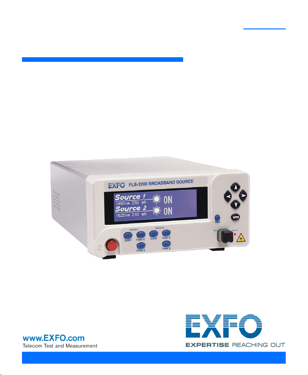
1 Introducing the FLS-2200
BROADBAND SOURCE
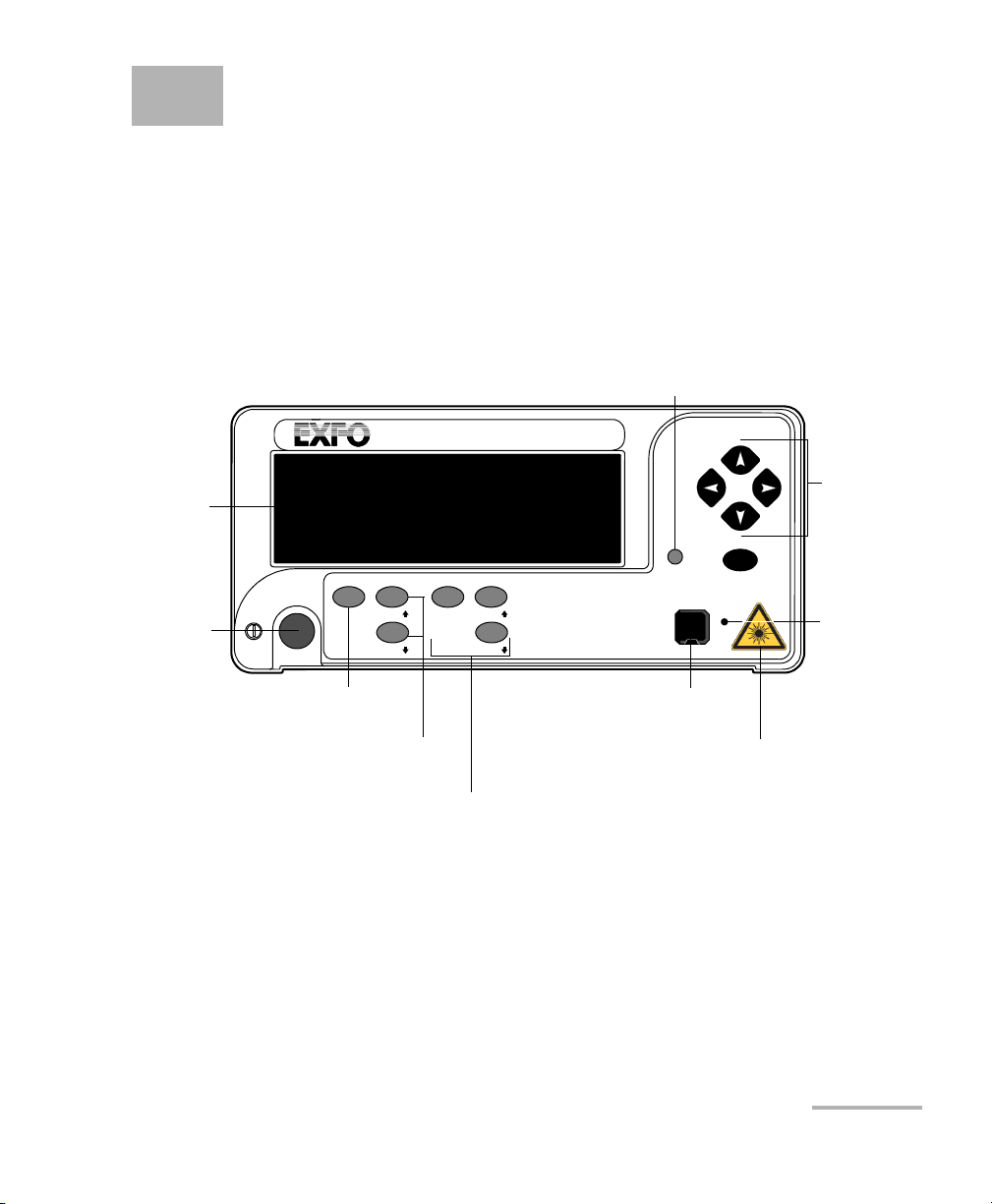
FLS-2200
ENTER
Setup
Active
Out
On/Off
Power
Power
Source 2
Navigation/
menu
setting
arrow keys
Setup menu access
Power
Source activation/
deactivation button
Display
Active LED
Output port
Drive-current increasing and
decreasing buttons
Second source control buttons
(on dual-source models only)
On/Off
Power
Power
Source 1
Laser radiation
hazard sticker
Broadband Source
Main Features
The FLS-2200 Broadband Source is a super-luminescent, light-emitting
diode (SLED) source covering all the bands needed for
telecommunications applications. It provides a broader spectral range and
more power density in a singlemode fiber than a white light source.
Broadband Source 1
Page 10
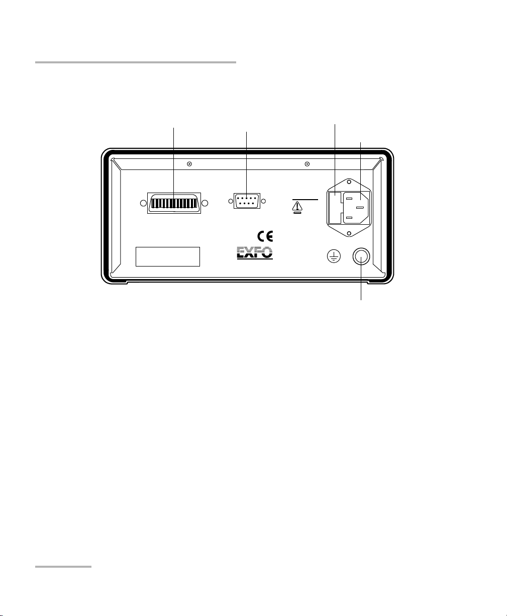
Introducing the FLS-2200 Broadband Source
Serial port (RS-232 DTE)
Fuse holder
Power inlet
GPIB port
400 Godin Ave.
Québec, Que., Canada G1M 2K2
GPIB IEEE 488.2
SH1, AH1, T6, L4, SR1, RL1, PP0, DC1, DT1, C0, E2
This device complies with part 15 of the FCC rules. Operation is
subject to the following two conditions: (1) this device may not cause
harmful interference and (2) this devic e must accept any interference
received, including interference that may cause undesired operation.
Made in Canada
P/N
S/N
Ver.
Mfg.
date
QST-151E
Serial Port
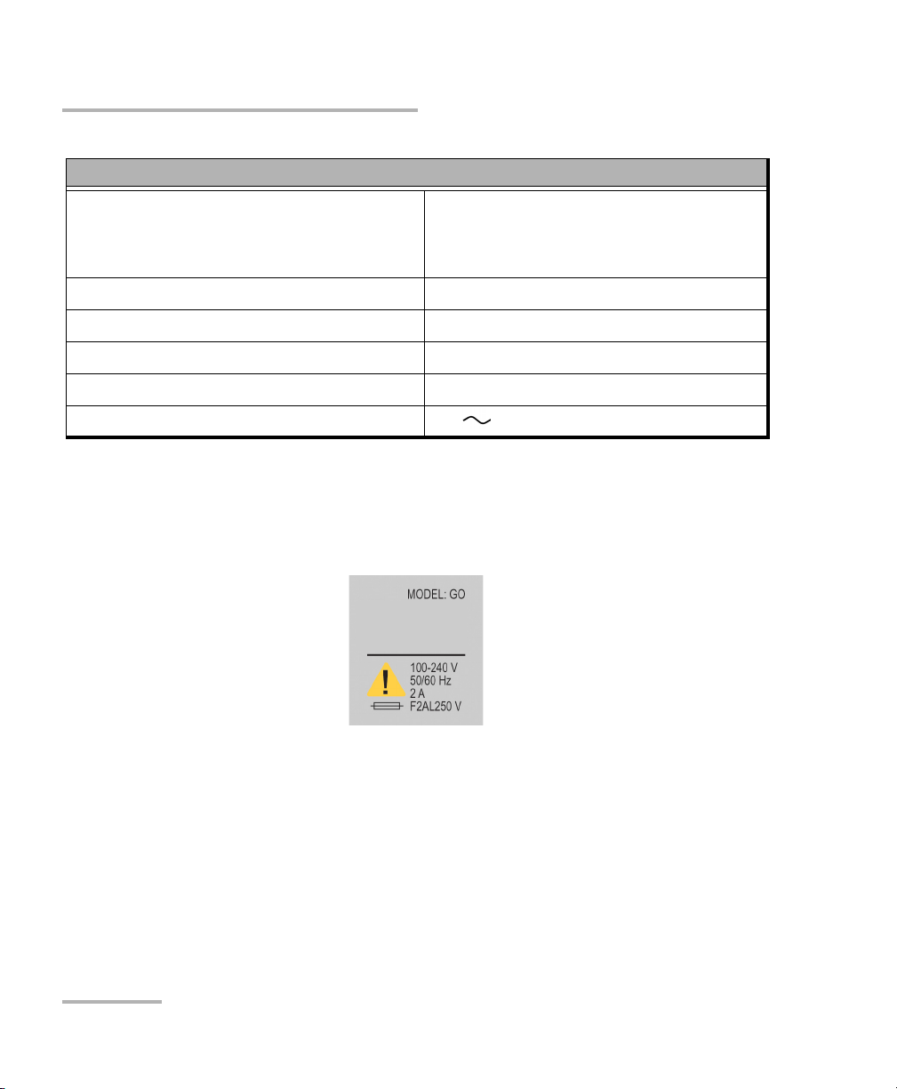
MODEL: GO
100-240 V
50/60 Hz
2 A
F2AL250 V
Ground
Available Models
On the back panel, you will find the ports for remote control, the power
inlet and fuse holder.
The FLS-2200 Broadband Source supports local control (via its front panel)
and remote control (through GPIB or RS-232 using SCPI commands or the
provided LabVIEW drivers).
Available Models
The FLS-2200 Broadband Source is available in the following models:
Models with a single super LED (SLED) covering a conventional
wavelength range (5 models).
Models with two SLEDs, covering a wider range for coarse
wavelength-division multiplexing (CWDM) and dual-window
applications (2 models).
2 FLS-2200
Page 11

Introducing the FLS-2200 Broadband Source
BROADBAND SOURCE
FLS-2200
ENTER
Setup
Active
Out
On/Off
Power
Power
Source 2
On/Off
Power
Power
Source 1
Optical Spectrum Analyzer
IQS-5250B
INPUT
DUT
Typical Applications
Typical Applications
You can use this light source to:
qualify components during development or to perform Pass/Fail tests
during production when you use the source with an optical spectrum
analyzer (OSA).
perform maintenance or troubleshooting tasks on a WDM network
when the source is combined with an OSA.
perform polarization mode dispersion (PMD) measurements when
you use the source with the FPMD-5600 Femtosecond PMD Analyzer
and the M9700 Passive Depolarizer.
perform polarization-dependent loss (PDL) measurements when you
use the source with an OSA.
The typical devices tested include passive optical network (PON)
components, CWDM components, attenuators, photonic switches,
broadband couplers, specialty couplers or multiplexers, Bragg gratings (the
source features a bandwidth large enough to test many Bragg gratings
simultaneously), etc.
A typical setup including both the FLS-2200 Broadband Source and an
IQS-5250B Optical Spectrum Analyzer is shown below.
Broadband Source 3
Page 12

Introducing the FLS-2200 Broadband Source
Conventions
Conventions
Before using the product described in this guide, you should understand
the following conventions:
WARNING
Indicates a potentially hazardous situation which, if not avoided,
could result in death or serious injury. Do not proceed unless you
understand and meet the required conditions.
CAUTION
Indicates a potentially hazardous situation which, if not avoided,
may result in minor or moderate injury. Do not proceed unless you
understand and meet the required conditions.
CAUTION
Indicates a potentially hazardous situation which, if not avoided,
may result in component damage. Do not proceed unless you
understand and meet the required conditions.
IMPORTANT
Refers to information about this product you should not overlook.
4 FLS-2200
Page 13

2 Safety Information
WARNING
Do not install or terminate fibers while a light source is active.
Never look directly into a live fiber and ensure that your eyes are
protected at all times.
WARNING
The use of controls, adjustments and procedures other than those
specified herein may result in exposure to hazardous situations or
impair the protection provided by this unit.
IMPORTANT
When you see the following symbol on your unit , make sure
that you refer to the instructions provided in your user
documentation. Ensure that you understand and meet the required
conditions before using your product.
Your instrument is a Class 1M laser product in compliance with standards
IEC 60825-1 2007 and 21 CFR 1040.10. Invisible laser radiation may be
encountered at the output port.
The product is safe under reasonably foreseeable conditions of operation
but it may be hazardous if you use optics within a diverging or collimated
beam. Do not view directly with optical instruments.
The following label(s) indicate that the product contains a Class 1M source:
Broadband Source 5
Page 14

Safety Information
Electrical Safety Information
Electrical Safety Information
This unit uses an international safety standard three-wire power cable. This
cable serves as a ground when connected to an appropriate AC power
outlet.
Note: If you need to ensure that the unit is completely powered off, disconnect the
power cable.
WARNING
Insert the power cable plug into a power outlet with a
protective ground contact. Do not use an extension cord
without a protective conductor.
Before powering on the unit, connect all grounding terminals,
extension cords and devices to a protective ground via a ground
socket. Any interruption of the protective grounding is a
potential shock hazard and may cause personal injury.
Whenever the ground protection is impaired, do not use the
unit and secure it against any accidental operation.
Do not tamper with the protective ground terminal.
The color coding used in the electric cable depends on the cable. New
plugs should meet the local safety requirements and include:
adequate load-carrying capacity
ground connection
cable clamp
IMPORTANT
EXFO assumes no liability if you attempt to perform internal service
on this unit.
6 FLS-2200
Page 15

Safety Information
Electrical Safety Information
WARNING
Use this unit indoors only.
Position the unit so that the air can circulate freely around it.
Operation of any electrical instrument around flammable gases
or fumes constitutes a major safety hazard.
Do not remove unit covers during operation.
To avoid electrical shock, do not operate the unit if any part of
the outer surface (covers, panels, etc.) is damaged.
Only authorized personnel should carry out adjustments,
maintenance or repair of opened units under voltage. A person
qualified in first aid must also be present. Do not replace any
components while power cable are connected.
Use only fuses with the required rated current and specified
type (IEC, 5 mm x 20 mm (0.197 in x 0.787 in), fast-blow, 250 V,
2 A). Do not use repaired fuses or short-circuited fuse holders.
Capacitors inside the unit may be charged even if the unit has
been disconnected from its electrical supply.
Broadband Source 7
Page 16
Safety Information
Electrical Safety Information
Equipment Ratings
Tem pe rat ur e
Operation
Storage
Relative humidity
a
0 °C to 40 °C (32 °F to 104 °F)
-40 °C to 70 °C (-40 °F to 158 °F)
0 % to 80 % non-condensing
Maximum operation altitude 2000 m (6562 ft)
Pollution degree 2
Overvoltage category II
Power supply rating
a. Measured in 0 °C to 31 °C (32 °F to 87.8 °F) range, decreasing linearly to 50 % at 40 °C (104 °F).
b. Not exceeding
b
± 10 % of the nominal voltage.
100 V - 240 V; 50 Hz/60 Hz; 2 A
The following label is located on the back panel of the unit:
8 FLS-2200
Page 17
3 Getting Started with Your
2
3
4
1
Broadband Source
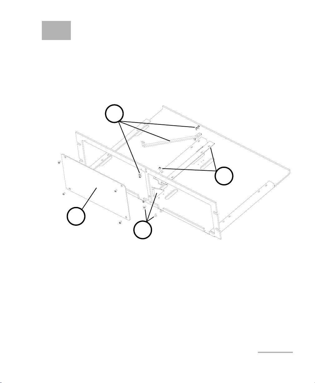
You can place your FLS-2200 Broadband Source in a rackmount to facilitate
its usage.
To install the rackmount:
1. Fix the angle iron using four flat Phillips screws.
2. Fix the rackmount bracket to the frame using two round Phillips
screws.
3. Fix the rackmount stiffener using two flat Phillips screws (for the front
panel) and two round Phillips screws.
4. If your rackmount will contain only one unit, fix the rackmount cover
plate to the empty part of the frame using four flat Phillips screws.
Broadband Source 9
Page 18
Getting Started with Your Broadband Source
X
A
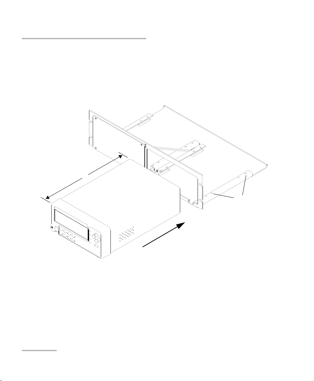
To install your FLS-2200 Broadband Source in a rackmount:
1. Slide the benchtop unit into the rackmount and tighten it from
underneath using the four cover fixing screws.
If measurement X on the illustration exceeds 11.125 in., fix the unit into
the four holes identified as A. Otherwise, use the other four holes.
2. If a second benchtop is to be installed, remove the cover plate and
repeat step 1.
10 FLS-2200
Page 19
Getting Started with Your Broadband Source
Bare metal
(or blue border)
indicates UPC
option
Green border
indicates APC
option
2 3 4
Installing the EXFO Universal Interface (EUI)
Installing the EXFO Universal Interface (EUI)
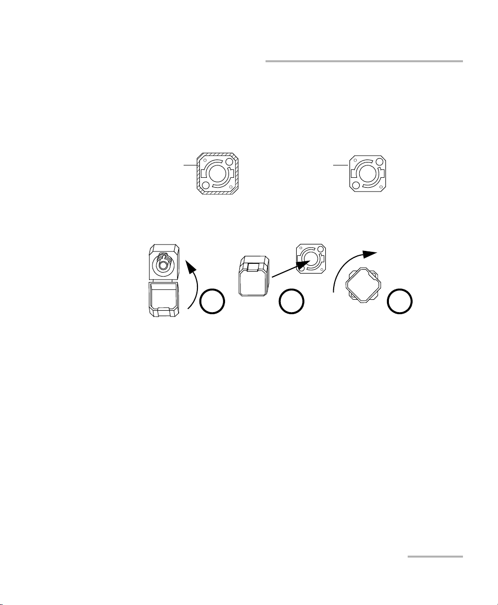
The EUI fixed baseplate is available for connectors with angled (APC) or
non-angled (UPC) polishing. A green border around the baseplate
indicates that it is for APC-type connectors.
To install an EUI connector adapter onto the EUI baseplate:
1. Hold the EUI connector adapter so the dust cap opens downwards.
2. Close the dust cap in order to hold the connector adapter more firmly.
3. Insert the connector adapter into the baseplate.
4. While pushing firmly, turn the connector adapter clockwise on the
baseplate to lock it in place.
Broadband Source 11
Page 20
Getting Started with Your Broadband Source
RM
LK
Source 1
OFF
1300 nm 210 mA
Source 2
OFF
1550 nm 191 mA
Remote control
Remotely-locked front panel
Wavelength
and drive
current
Source status
Information on second source
(dual-source models only)
Source number (dual-source
models only)
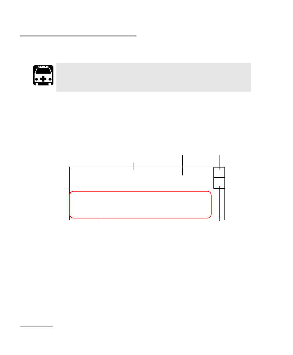
Turning On/Off the Broadband Source
Turning On/Off the Broadband Source
WARNING
Before turning on the source, read Electrical Safety Information on
page 6.
To turn the Broadband Source on and off:
Press the red button located in the lower left-hand corner of the front
panel.
Upon startup, the unit beeps twice, performs a self-test and then displays
the main window, indicating that all sources are deactivated (OFF).
12 FLS-2200
Page 21

Getting Started with Your Broadband Source
Turning On/Off the Broadband Source
The source status indicator shows whether the source is active or not
(ON/OFF). In the case of an active source, a graphical element
representing a light beam is also displayed.
The wavelength and drive current indicator shows the source’s
nominal wavelength (in nanometers) and the selected drive current
(in milliamperes).
The remote control indicator (RM) appears when the unit is currently
controlled by remote commands (via GPIB or RS-232 communication).
Note: You must set the GPIB bus line to True in GPIB or send the *REM command
in RS-232 for the remote control indicator to be displayed.
The remotely-locked keyboard indicator (LK) shows that a remote
application is preventing you from using the unit’s front panel buttons
(keyboard)—except the red button used to turn the unit on or off.
When the unit is turned off, the current Setup menu settings remain in the
unit’s memory. These settings include display features and remote control.
Broadband Source 13
Page 22

Getting Started with Your Broadband Source
Installing EXFO LabVIEW Drivers
Installing EXFO LabVIEW Drivers
Before being able to work with EXFO LabVIEW drivers, you must install the
following elements on your computer:
National Instruments LabVIEW software and the corresponding
patches.
EXFO LabVIEW drivers (including demo applications to help you get
started with the drivers)
For information on these applications, see Working with EXFO LabVIEW
Drivers on page 52.
Note: Only administrator-level users can install software under Windows XP.
To install the LabVIEW software:
1. Insert the LabVIEW CD in the CD-ROM drive.
2. The installation process should start automatically. If not, start it
manually as follows:
2a. On the Windows taskbar, click Start and select Run.
2b. In the Open box locate the autorun.exe file.
2c. Click OK to start the installation procedure and follow the
on-screen instructions.
You should keep the default names and paths suggested by the
installation program.
3. Once the software installation is complete, install the patches available
for your LabVIEW version.
If the patches are not included on your LabVIEW CD, you may
download them from National Instruments’ Web site at www.ni.com.
3a. On the Windows taskbar, click Start and select Run.
3b. In the Open box, locate Updates\setup.exe.
14 FLS-2200
Page 23

Getting Started with Your Broadband Source
Installing EXFO LabVIEW Drivers
3c. Click OK to start the installation procedure and follow the
on-screen instructions.
To install the EXFO LabVIEW drivers:
1. Insert the installation CD in the CD-ROM drive.
2. Start the installation process as follows:
2a. On the Windows taskbar, click Start and select Run.
2b. In the Open box, locate Labview Drivers\setup.exe on the storage
device where the drivers are located.
2c. Click OK to start the InstallShield Wizard and follow the on-screen
instructions.
For easier use, the drivers will be installed in LabVIEW’s default
instrument library folder:
C:\Program Files\National Instruments\LabVIEW 6\instr.lib\EXFO.
Broadband Source 15
Page 24

Page 25

4 Setting Up Your Broadband
Refresh Rate
Backlight
Contrast
Video Mode
8 Hz
ON
STD
Exit
RS232 / GPIB
GPIB Addr.
Baud Rate
Flow Ctrl
GPIB
12
N.A.
N.A.
Source
The blue button on the right of the display provides access to the
single-level Setup menu. You can access this menu even while the source
is active to set up the various parameters.
Setting the Refresh Rate
To set the refresh rate:
1. Press the Setup button.
2. Use the up/down or left/right arrow keys to select Refresh Rate (the
item will be displayed in reverse video).
3. Press ENTER to access the Refresh Rate edit box.
4. Use the up/down arrow keys to set the refresh rate between 1/2 Hz,
1Hz, 2Hz, 4Hz, 8Hz and 16Hz.
5. Press ENTER to confirm the new refresh rate.
Broadband Source 17
Page 26

Setting Up Your Broadband Source
Activating or Deactivating the Backlight
Activating or Deactivating the Backlight
To deactivate the backlight:
1. Press the Setup button.
2. Use the up/down or left/right arrow keys to select Backlight (the item
will be displayed in reverse video).
3. Press ENTER to access the Backlight edit box.
4. Use the up/down arrow keys until the backlight value changes to OFF.
5. Press ENTER to confirm the new backlight setting.
To reactivate the backlight:
Stand very close to the unit to see the information displayed. Repeat
steps 1 to 4 above—except that you must set the backlight value to ON.
OR
Reset the unit to the default parameters (see Reverting the Broadband
Source to Default Settings on page 21).
Setting the Contrast
To set the contrast:
1. Press the Setup button.
2. Use the up/down or left/right arrow keys to select Contrast (item will
appear in reverse video).
3. Press ENTER to access the Contrast edit box.
4. Use the up/down arrow keys to adjust the contrast as required.
5. Press ENTER to confirm the contrast adjustment.
18 FLS-2200
Page 27
Setting Up Your Broadband Source
Refresh Rate
Backlight
Contrast
Video Mode
Exit
8 Hz
ON
STD
RS232 / GPIB
GPIB Addr.
Baud Rate
Flow Ctrl
GPIB
12
N.A.
N.A.
Refresh Rate
Backlight
Contrast
Video Mode
Exit
ON
INV
RS232 / GPIB
GPIB Addr.
Flow Ctrl
GPIB
12
N.A.
N.A.
Baud Rate
Exit
8 Hz
Baud Rate
Setting the Video Mode
Setting the Video Mode
To set the video mode:
1. Press the Setup button.
2. Use the up/down or left/right arrow keys to select Video Mode (item
will appear in reverse video).
3. Press ENTER to access the Video Mode edit box.
4. Use the up/down arrow keys to set the required video mode (standard
or reverse).
5. Press ENTER to confirm the video mode.
Broadband Source 19
Page 28

Setting Up Your Broadband Source
BROADBAND SOURCE
FLS-2200
ENTER
Setup
Active
Out
On/Off
Power
Power
Source 2
Increasing and decreasing buttons
On/Off
Power
Power
Source 1
Power
Power
Setting the Drive Current
Setting the Drive Current
You can adjust the source’s drive current to better suit your needs. The
drive current can be increased or decreased by steps of 1 mA or 10 mA.
On a dual-source, each one has its own set of control buttons and has an
independent drive current value.
Note: You can set the drive current even while the source is not emitting.
To set the drive current:
1. Press the button to increase the value by steps of 1 mA.
OR
Press the button to decrease the value by steps of 1 mA.
2. To increase or decrease the value by steps of 10 mA, hold the
corresponding button down.
The displayed current value on the screen changes accordingly.
3. If you have a dual-source, you can repeat the above steps to set the
drive current for the second source.
20 FLS-2200
Page 29

Setting Up Your Broadband Source
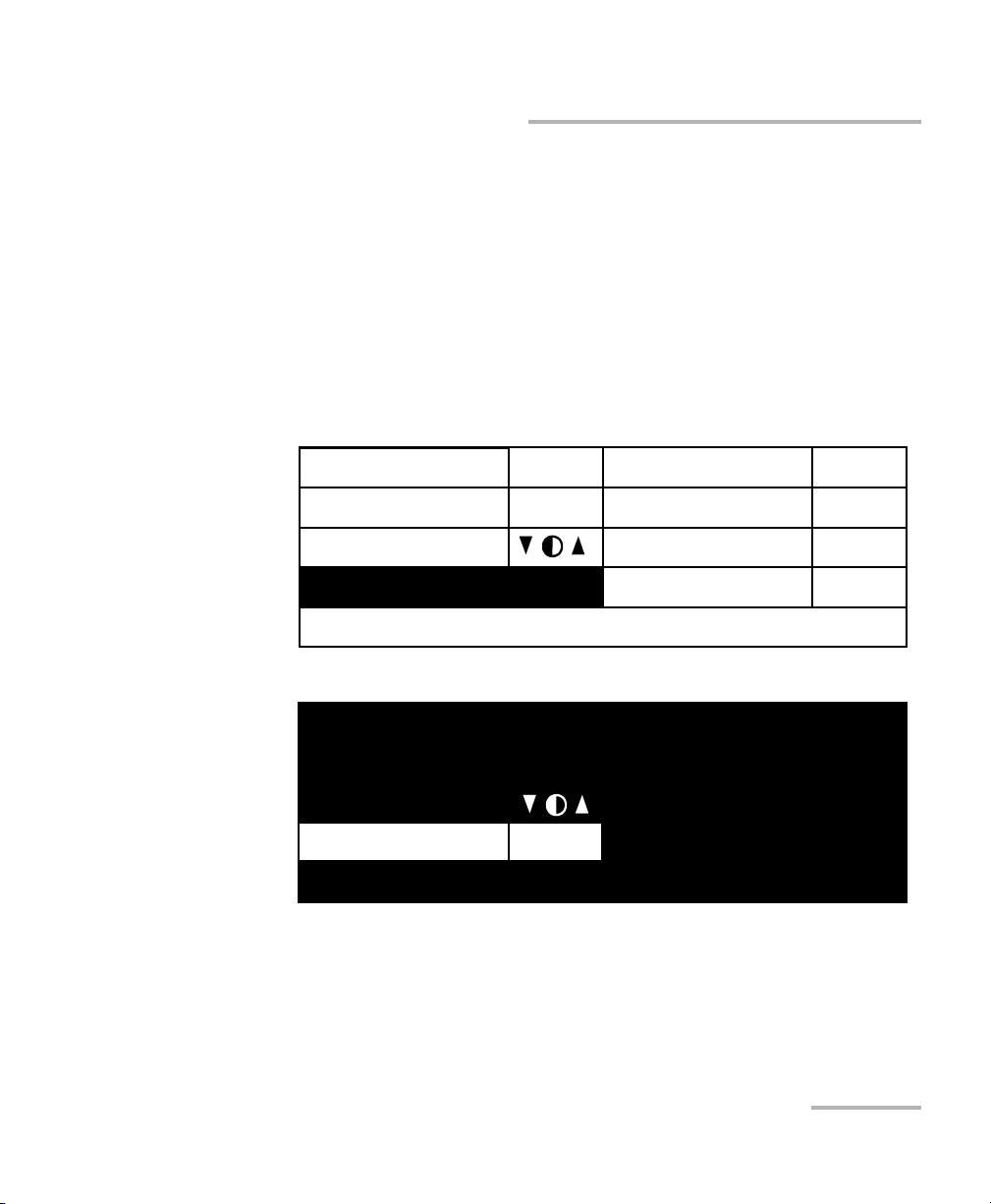
Reverting the Broadband Source to Default Settings
Reverting the Broadband Source to Default
Settings
You may want to revert the Broadband Source to the factory settings.
The following table presents the parameters and their default values.
Parameters Default Values
Source OFF
Drive current Minimum value
Backlight ON
Videomode STD (standard)
Refresh rate 4 Hz
RS232/GPIB (Remote control)
GPIB address
Baud rate
Flow ctrl
a
a
a
a
GPIB
12
N.A.
N.A.
a. Parameter cannot be reset by a remote control command.
To revert the source to default settings:
1. Turn off the unit.
2. Turn on the unit and press ENTER at the same time until the unit beeps
three times.
Broadband Source 21
Page 30

Page 31

5 Operating the Broadband
Source
Cleaning and Connecting Optical Fibers
IMPORTANT
To ensure maximum power and to avoid erroneous readings:
Always inspect fiber ends and make sure that they are clean as
explained below before inserting them into the port. EXFO is
not responsible for damage or errors caused by bad fiber
cleaning or handling.
Ensure that your patchcord has appropriate connectors. Joining
mismatched connectors will damage the ferrules.
To connect the fiber-optic cable to the port:
1. Inspect the fiber using a fiber inspection microscope. If the fiber is
clean, proceed to connecting it to the port. If the fiber is dirty, clean it as
explained below.
2. Clean the fiber ends as follows:
2a. Gently wipe the fiber end with a lint-free swab dipped in isopropyl
alcohol.
2b. Use compressed air to dry completely.
2c. Visually inspect the fiber end to ensure its cleanliness.
Broadband Source 23
Page 32

Operating the Broadband Source
Cleaning and Connecting Optical Fibers
3. Carefully align the connector and port to prevent the fiber end from
touching the outside of the port or rubbing against other surfaces.
If your connector features a key, ensure that it is fully fitted into the
port’s corresponding notch.
4. Push the connector in so that the fiber-optic cable is firmly in place,
thus ensuring adequate contact.
If your connector features a screwsleeve, tighten the connector
enough to firmly maintain the fiber in place. Do not overtighten, as this
will damage the fiber and the port.
Note: If your fiber-optic cable is not properly aligned and/or connected, you will
notice heavy loss and reflection.
EXFO uses good quality connectors in compliance with EIA-455-21A
standards.
To keep connectors clean and in good condition, EXFO strongly
recommends inspecting them with a fiber inspection probe before
connecting them. Failure to do so will result in permanent damage to the
connectors and degradation in measurements.
24 FLS-2200
Page 33

Operating the Broadband Source
BROADBAND SOURCE
FLS-2200
ENTER
On/Off
Power
Setup
Active
Out
On/Off
Power
Power
Power
Source 1
Source 2
Source activation/
deactivation button
Activating or Deactivating a Source
Activating or Deactivating a Source
On a dual-source, each one has its own set of control buttons and can be
activated or deactivated separately (both ON, both OFF, one ON and one
OFF).
When lit, the active LED indicates that an optical signal is being emitted
from the source port.
For your safety, the Broadband Source provides a three-second safety delay
between the source activation and actual light emission. You can also stop
light emission at any time by pressing on the activation/deactivation button.
Broadband Source 25
Page 34

Operating the Broadband Source
Active source
RM
LK
Source 1
ON
1300 nm 210 mA
Source 2
OFF
1550 nm 191 mA
Information
on second
source
(dual-source
models only)
Activating or Deactivating a Source
To activate a source:
1. Press the activation/deactivation button (labeled On/Off).
Note: If you have a dual-source, make sure you use the appropriate set of buttons
(Source 1 or Source 2).
The active LED on the unit front panel will light up, and the display will
read “Source x ON”, also showing a light beam icon. The word “ON”
will flash during the three-second safety delay.
2. If you have a dual-source, you can repeat step 1 to activate the second
one.
IMPORTANT
To obtain optimum stability, let the source warm up for 30 minutes.
To deactivate a source:
1. Press the activation/deactivation button (labeled On/Off).
The active LED on the module front will turn off and the display will
read “Source x OFF”.
2. If you have a dual-source, you can repeat the above step to deactivate
the second one source.
26 FLS-2200
Page 35

6 Preparing for Remote Control
GPIB port
The Broadband Source can be controlled remotely either by GPIB or
RS-232.
Note: When the Broadband Source is being controlled remotely, RM appears in
the upper right corner of the display.
EXFO supplies commands that follow the guidelines determined by the
SCPI consortium. The same commands are used in both GPIB and RS-232
communication. You can find detailed information about these commands
in the IEEE 488.2 and Specific Command Reference appendix.
Linking Units with the GPIB Port
Your FLS-2200 Broadband Source is equipped with a GPIB port. You can
simply use a GPIB cable to link it to the other unit with which you want to
perform remote control. The GPIB port is located at the back of Broadband
Source, as shown below.
Broadband Source 27
Page 36

Preparing for Remote Control
Serial port
1234 5
6789
Linking Units with the Serial Port
Linking Units with the Serial Port
Your FLS-2200 Broadband Source is equipped with a serial (RS-232) port to
send and receive data. You can simply use a null-modem (serial) cable to
link it to the other unit with which you want to perform remote control. The
RS-232 port is located at the back of Broadband Source, as shown below.
The RS-232 connector uses a DTE pinout configuration.
Pin Description Direction
2 Receive (Rx) Input
3 Transmit (Tx) Output
5 Ground (Gnd) —
28 FLS-2200
Page 37

Preparing for Remote Control
Changing Communication Settings
Changing Communication Settings
To re m ot el y c on tr ol yo ur Broadband Source, you must set a GPIB address
or activate the RS-232 port.
Note: Communication settings cannot be modified without turning on your unit.
The tables present the different parameters for GPIB and RS-232
communication and their corresponding values.
Note: EOS means “End of String.” EOI means “End of Identify.”
Parameters for GPIB Communication
Terminate Read on EOS Yes
Set EOI with EOS on Writes Yes
Type of compare on EOS 8 bits
EOS byte 0Ah
Send EOI at end of Writes Yes
GPIB primary address Value between 1 and 30 (default value: 12)
GPIB secondary address None
Parameters for RS-232 Communication
EOS bytes 0Ah
Baud rate 1200/2400/4800/9600/19200 bps
Parity None
Data bits 8 bits
Stop bits 1 bit
Flow control Software (Xon/Xoff) or None
Broadband Source 29
Page 38

Preparing for Remote Control
Refresh Rate
Backlight
Contrast
Video Mode
Exit
8 Hz
ON
STD
RS232 / GPIB
GPIB Addr.
Baud Rate
Flow Ctrl
GPIB
12
N.A.
N.A.
Setting the Remote Control Mode
Setting the Remote Control Mode
To remotely control the Broadband Source, you must either
select the GPIB mode by setting a GPIB address, or
activate the RS-232 port and set its parameters (see Setting Baud Rate
on page 32 and Setting Flow Control on page 33).
To set a remote control mode:
1. Press the Setup button.
2. Use the up/down or left/right arrow buttons to select RS232/GPIB.
Note: If GPIB is currently selected and you want to specify a GPIB address, see
Setting GPIB Address on page 31.
3. Press ENTER to access the RS232 / GPIB edit box.
4. Use the up/down arrow keys to toggle between GPIB and RS232.
5. Press ENTER to confirm.
If you selected RS232, the GPIB Addr. menu option is deactivated (“N.A.”is
displayed).
If you selected GPIB, the Baud Rate and Flow Ctrl menu options are
disabled (“N.A.” is displayed). If the currently selected GPIB address
doesn’t suit your needs, you can change it.
30 FLS-2200
Page 39

Preparing for Remote Control
Refresh Rate
Backlight
Contrast
Video Mode
Exit
8 Hz
ON
STD
RS232 / GPIB
GPIB Addr.
Baud Rate
Flow Ctrl
GPIB
12
N.A.
N.A.
Setting GPIB Address
Setting GPIB Address
If GPIB is selected as the remote command mode, you can select the GPIB
address you want to use from 1 to 30 (default value is 12).
To set a GPIB address:
1. Press the Setup button.
2. Use the up/down or left/right arrow keys to select GPIB Addr. The
current GPIB address is displayed.
Note: If you are in RS-232 mode, the GPIB address cell will display “N.A.” You
must change the communication mode to GPIB before setting an address.
3. Press ENTER, then use the up/down arrow keys to select a GPIB
address between 1 and 30.
4. Press ENTER to confirm your choice.
Broadband Source 31
Page 40

Preparing for Remote Control
Refresh Rate
Backlight
Contrast
Video Mode
Exit
8 Hz
ON
STD
RS232 / GPIB
GPIB Addr.
Baud Rate
Flow Ctrl
RS232
N.A.
19200
Soft
Setting Baud Rate
Setting Baud Rate
The baud rate is a parameter related to RS-232 communication. It
determines the speed at which data is sent between the unit and a
computer, in bits per second (bps).
To change the baud rate for your remote communications:
1. Press the Setup button.
2. Use the up/down or left/right arrow keys to select Baud Rate. The
current setting is displayed.
Note: If you are in GPIB mode, the Baud Rate cell will display “N.A.” You must
change the communication mode to RS-232 before setting the baud rate.
3. Press ENTER, then use the up/down arrow keys to select the baud rate.
You can select 1200, 2400, 4800, 9600 or 19200 bps.
4. Press ENTER to confirm.
32 FLS-2200
Page 41

Preparing for Remote Control
Refresh Rate
Backlight
Contrast
Video Mode
Exit
8 Hz
ON
STD
RS232 / GPIB
GPIB Addr.
Baud Rate
Flow Ctrl
RS232
N.A.
19200
Soft
Setting Flow Control
Setting Flow Control
The flow control parameter applies only to RS-232 communication. This
parameter allows you to select the type of serial communication used.
You can choose the Soft option if you want the rate of data transmission to
match the rate at which it can be processed by the device. This enables the
computer and the Broadband Source to stop each other from transmitting
by sending a control character (Xoff). They will also be able to restart the
transmission by sending another control character (Xon). This is known as
a “software handshake”.
To set a flow control:
1. Press the Setup button.
2. Use the up/down or left/right arrow keys to select Flow Ctrl. The
current setting is displayed.
Note: If you are in GPIB mode, the Flow Ctrl cell will display “N.A.” You must
change the communication mode to RS-232 before setting the flow control.
3. Press ENTER, then use the up/down arrow keys to select the type of
flow you want. “None” means no flow control. “Soft” allows the unit or
computer controlling it, to turn the data transmission on or off.
4. Press ENTER to confirm.
Broadband Source 33
Page 42

Page 43

7 Using Your Broadband Source
in an Automated Test
Environment
EXFO supplies commands that follow the guidelines determined by the
SCPI consortium and LabVIEW drivers for your FLS-2200 Broadband
Source. Your application can be developed using LabVIEW.
The present chapter gives you information to help you use the provided
commands and drivers to remotely control your Broadband Source.
Message Management
Each device that is physically connected to the GPIB link has its own input
buffer, output queue and error/event queue. These data structures allow
storage of incoming messages (single or compound commands that are
sent to an instrument), responses from queries, errors and events that may
occur.
Data structure Characteristics Clearing
Input buffer Consists of a First-In, First-Out
(FIFO) data structure.
Stores Data Bytes (DABs) and END
messages.
Delivers messages to the parser in
the order that they were received
from the I/O control.
Maximum message length:
unlimited in DABs (the input
buffer size is only limited to the
total size of the device memory).
Broadband Source 35
The buffer will be cleared
by:
Turning off the power.
Sending a Device Clear
(DCL) message to the
instrument.
Sending a
Selected Device Clear
(SDC) message to the
instrument.
Page 44

Using Your Broadband Source in an Automated Test Environment
Message Management
Data structure Characteristics Clearing
An incoming byte empties the
output queue. An error will be
raised if the output queue
contained data. Consequently, it
clears the Message AVailable bit
(bit number 4 –MAV from the
Status Byte register).
Except for the string and binary
block contents, the following
transformations are made on the
incoming data:
character conversion from lower
case to upper case.
conversion of “<wsp>”
characters to spaces.
conversion of multiple blanks to a
single blank.
Parser begins to process messages
when the <PROGRAM MESSAGE
TERMINATOR> is received or if
the input buffer is full.
36 FLS-2200
Page 45

Using Your Broadband Source in an Automated Test Environment
Message Management
Data structure Characteristics Clearing
Output queue Consists of a First-In, First-Out
(FIFO) data structure.
When the instrument acts as a
talker, it sends response messages
(from the output queue) to the
controller. Response messages all
end with a <RESPONSE MESSAGE
TERMINATOR>, see the appendix
on data types.
Total storage capacity: only limited
to the device’s memory.
As soon as there is data in the
output queue, the Message
AVailable bit (bit number 4 –MAV
from the Status Byte register) is set
to 1.
Remains empty if no query is
received or if the query contains
an error.
The Output queue will be
cleared by:
Reading all the items it
contains.
Turning off the power.
Sending a Device Clear
(DCL) message to the
instrument.
Sending a
Selected Device Clear
(SDC) message to the
instrument.
Attempting to send a
command before
reading the responses to
previous queries (an
error will also be
raised).
Broadband Source 37
Page 46

Using Your Broadband Source in an Automated Test Environment
Message Management
Data structure Characteristics Clearing
Error/Event
queue
Consists of a First-In, First-Out
(FIFO) data structure.
Total storage capacity: 50 errors or
events.
Errors or events can be retrieved,
one at a time, with
:SYSTem:ERRor[:NEXT]?.
When an error or event occurs
and the Error/Event queue is full,
the last item in the queue (the
most recent) is removed and the
Queue overflow error
(error –350) is added. No new
items will be stored into the queue
until there will be room available.
As soon as there is data in the
output queue, the Error AVailable
bit (bit number 2 –EAV from the
Status Byte register) is set to 1.
The Error/Event queue will
be cleared when:
Reading all the items it
contains.
Turning off the power.
Sending a Device Clear
(DCL) message to the
instrument.
Sending a
Selected Device Clear
(SDC) message to the
instrument.
Using the *CLS
command.
38 FLS-2200
Page 47

Using Your Broadband Source in an Automated Test Environment
Standard Status Data Structure
Standard Status Data Structure
Each device that is physically connected to the GPIB bus has four status
registers with a structure complying with the IEEE 488.2 standard. These
registers allow the controller to monitor events and get useful information
on the status of the devices it controls.
Standard Event Status Register (ESR)
Bits Mnemonics Bit Value
7 Power On 128
6Not used 0
5 Command Error 32
4Execution Error 16
3 Device Dependent Error 8
2Query Error 4
1Not used 0
0Operation Complete 1
Broadband Source 39
Page 48

Using Your Broadband Source in an Automated Test Environment
Standard Status Data Structure
Standard Event Status Enable Register (ESE)
Bits Mnemonics Bit Value
7 Power on 128
6Not used 0
5 Command error 32
4Execution error 16
3 Device dependent error 8
2Query error 4
1Not used 0
0 Operation complete 1
The following table presents a summary of the possible operations on ESR
and ESE registers.
Register Read Write Clear
ESR Use *ESR?. Impossible to write. Use *CLS.
Read the register.
ESE Use *ESE?. Use *ESE. Use *ESE with a value
equal to 0.
40 FLS-2200
Page 49

Using Your Broadband Source in an Automated Test Environment
Standard Status Data Structure
Status Byte Register (STB)
Bits Mnemonics Bit Value
7Not used 0
6 Request service / Master summary status 64
5 Event summary bit 32
4 Message available 16
3Not used 0
2 Error / Event queue 4
1Not used 0
0Not used 0
Service Request Enable Register (SRE)
Bits Mnemonics Bit Value
7Not used 0
6 Reserved 0
5 Event status byte 32
4 Message available 16
3Not used 0
2 Error / Event queue 4
1Not used 0
0Not used 0
Broadband Source 41
Page 50

Using Your Broadband Source in an Automated Test Environment
Standard Status Data Structure
The following table presents a summary of the possible operations on STB
and SRE registers.
Register Read Write Clear
STB Use *STB?.
Use serial poll (GPIB
bus sequence that
allows retrieval of the
value without
Impossible to write;
the register’s contents
is only modified when
the Event registers or
Queues are modified.
interrupting the current
process).
SRE Use *SRE? Use *SRE with a value
equal to 0 to disable
the register or with a
value equal to 1 to
enable it.
The diagram displayed on the next page is a useful aid in understanding
the general commands and how a service request (SRQ) is generated.
Using a service request, a device notifies the controller that an event
requiring special attention occurred. The controller will then find which
device generated a SRQ (its RQS bit is set) and the causes of it.
Use *CLS before
sending a query (to
clear the Event registers
and Queues and by the
same token clear the
STB register).
Use *SRE with a value
equal to 0.
42 FLS-2200
Page 51

Using Your Broadband Source in an Automated Test Environment
Standard Status Data Structure
Broadband Source 43
Page 52

Using Your Broadband Source in an Automated Test Environment
SOUR:POW[:STAT]<wsp><Boolean Program Data>
Mandatory
keywords
Optional keyword
(in square brackets)
Required
space
ParameterKeyword
separators
SCPI Command Structure
SCPI Command Structure
The information presented in this section provides an overview of GPIB
programming. If you need detailed information, refer to:
The International Institute of Electrical and Electronics Engineers. IEEE
Standard 488.1-1987, IEEE Standard Digital Interface for Programmable
Instrumentation. New York, 1987.
The International Institute of Electrical and Electronics Engineers. IEEE
Standard 488.2-1992, IEEE Standard Codes, Formats, Protocols and
Common Commands For Use with ANSI/IEEE Std. 488.1-1987. New
York, 1992.
Standard Commands for Programmable Instruments (SCPI). Volume
1: Syntax and Style. Vers. 1999.0 May, U.S.A, 1999.
The provided commands follow the guidelines determined by the Standard
Commands for Programmable Instruments (SCPI) consortium. A program
message consists of one or more commands (and/or queries) with their
appropriate parameters.
Note: The command provided below is for guidance only; your Broadband
Source may not support it.
For example, a program message could contain a command used to
activate or deactivate a source. The corresponding command syntax
would be:
When sending a message containing the previous command, you would
44 FLS-2200
actually type: SOUR:POW ON.
Page 53

Using Your Broadband Source in an Automated Test Environment
SCPI Command Structure
The following table shows elements that are commonly used in the
commands or queries syntax.
Item Meaning
[ ] Enclose optional keywords or parameters.
Do not include square brackets in your program message.
[1..n] Indicates that the instrument provides multiple capabilities and that you
have to specify which one you want to use. If you omit the value, the
command will take effect on the first capability.
Multiple capabilities can be found at any branch of the command tree
(root, intermediate node or terminal node).
Example: If the command is :SENSe[1..n]:CORRection:COLLect:ZERO
and you want it to take effect on the second SENSe (sensor) capability
of the instrument, you may send this:
:SENSe2:CORRection:COLLect:ZERO.
Do not include square brackets in your program message; simply enter
the number.
<wsp> Indicates that a space is required (“wsp” stands for “white space”).
Corresponds to ASCII character codes (0 to 9 and 11 to 32, in decimal).
Do not include “<wsp>” in your program message; simply type a space.
<digit> Element used in the construction of various numeric data types. Can
take any value between 0 and 9 inclusively (corresponds to ASCII
character codes 48 to 57, in decimal).
Broadband Source 45
Page 54

Using Your Broadband Source in an Automated Test Environment
<Upper/lo wer
cas e alpha>
<Upper/l ower
cas e alpha>
_
<digi t>
SCPI Command Structure
Item Meaning
<mnemonic> Element used in the construction of certain data types and program
messages.
In the diagram above,
“<Upper/lower case alpha>” corresponds to ASCII character codes
(65 to 90 and 97 to 122, in decimal).
“_” corresponds to an underscore character (code 95, in decimal).
< > Text appearing between angled brackets specifies the command
parameter to be sent or the response you will receive from an
instrument.
Do not include angled brackets in your program message.
| Indicates that one, and only one, value must be selected from the
available choices.
Example: If the list is 0|1, you can only select 0 or 1.
Do not include the pipe character in your program message.
{ } Indicate that the enclosed parameters can appear 0 to n times when the
command is used.
Do not include braces in your program message.
: Mandatory to separate keywords. Can be omitted at the beginning of a
program message. For example, you can use either :SYST:ERR or
SYST:ERR.
46 FLS-2200
Page 55

Using Your Broadband Source in an Automated Test Environment
:SYSTem:ERRor?
:SYST:ERR?
:syst:err?
Long form
Short form (small words
represented by the capital letters
of the long form)
Item Meaning
SCPI Command Structure
;
Mandatory to separate the different commands of a program
message when more than one command is sent at a time. In this
case, it is called <PROGRAM MESSAGE UNIT SEPARATOR>.
Also used to separate responses when multiple queries were sent in
a single program message. In this case, it is called <RESPONSE
MESSAGE UNIT SEPARATOR>.
,
Mandatory to separate parameters in a command or a query. In this
case, it is called <PROGRAM DATA SEPARATOR>.
Also used to separate the various responses from a query. In this
case, it is called <RESPONSE DATA SEPARATOR>.
There are also several conventions regarding command syntax:
Spelling errors will cancel the command or query.
Commands and queries are not case-sensitive. You can type your
program messages using either lower-case or upper-case letters.
The command or query can be written using only the three- or
four-letter shortcuts, only full words, or a combination of both.
The example below shows the long and the short forms of a same
query.
For readability reasons, you can use extra spaces in your program
messages but they won’t be taken into account. For more information,
see Message Management on page 35.
Broadband Source 47
Page 56

Using Your Broadband Source in an Automated Test Environment
:system:version?;:system:error:next?
:system:version?;error:next?
other<mnemonic> path
<mnemonic> path
omitted –also correct
saved <mnemonic> path
:system:error:next?;:system:version?
:system:error:next?;version?
Incorrect; :version? is not in
the :system:error branch
other<mnemonic> pathsaved <mnemonic> path
SCPI Command Structure
You can build program messages allowing you to send more than one
command at a time. Sometimes, you can omit the leading
<mnemonic> path to simplify the program messages and speed up
the search time (the parser saves the last position in the command
tree).
Paths cannot be omitted in all cases. The example below would cause
an error.
IEEE 488.2 required commands or queries (beginning with a *) that are
part of the program message have no effect on the paths.
Example:
:system:version?;*idn?;:system:error:next? is equivalent to
:system:version?;*idn?;error:next?
Note: Omitting the leading <mnemonic> path is only possible when you have
more than one command or query in the program message that you send.
A program message must be ended with a <PROGRAM MESSAGE
TERMINATOR>. For more information, see the appendix on data types.
48 FLS-2200
Page 57

Using Your Broadband Source in an Automated Test Environment
Consulting Data Types
Consulting Data Types
If you need information about data types used in EXFO’s documentation,
see the appendix on data types.
Writing Remote Control Code
Complex measurement programs may be written using any programming
environment that supports GPIB communication. GPIB development kits
are available for most of the popular commercial programming languages.
You can find all the commands and queries supported by the Broadband
Source in the IEEE 488.2 and Specific Commands appendix.
Broadband Source 49
Page 58

Using Your Broadband Source in an Automated Test Environment
Writing Remote Control Code
When you write code, you must follow these rules on message reception
and transmission:
The controller must have sent a complete message to the instrument
(including the message terminator) before retrieving a response.
The controller must retrieve all the responses from previous queries
(including the response terminator) before sending a new message to
an instrument.
The controller must not try to retrieve a response from an instrument if
the corresponding query has not been previously sent to the
instrument.
You must pay special attention to queries that return an indefinite ASCII
response. To avoid any confusion, the IEEE 488.2 standard requires that
this data type be immediately followed by a response termination
character. For this reason, when working with compound queries, you
must ensure that a query sending an indefinite ASCII response is the
last query of the series.
Be careful when sending program messages containing multiple
queries that return large amounts of data. Since the controller can only
retrieve data when the instrument has finished processing the queries,
it could result in problems ranging from a saturation of the output
queue to the complete blocking of the whole system.
50 FLS-2200
Page 59

Using Your Broadband Source in an Automated Test Environment
<Error
number>
, "
<Error
description>
; "
<Device
dependent
information>
Error Message Format
Error Message Format
System and device-specific errors are managed by the FLS-2200
Broadband Source. The generic format for error messages is illustrated in
the following figure.
As shown in the above figure, the message contains three parts:
error number
error description
device-dependent information
Error messages ending in a negative number are SCPI-based errors.
For more information on errors, see Message Management on page 35. For
a complete list of possible errors, seethe appendix on SCPI-based errors.
Broadband Source 51
Page 60

Using Your Broadband Source in an Automated Test Environment
Perform all operations on
instrument
Set up communication
parameters
Open communication
Close communication
Working with EXFO LabVIEW Drivers
Working with EXFO LabVIEW Drivers
EXFO provides you with custom drivers that you can use to program
commands for your inspection instruments.
IMPORTANT
You need to be familiar with the LabVIEW environment and
programming methods to work with EXFO drivers.
Regardless of whether you work with the provided Getting Started
applications or your own VIs (using EXFO drivers), the steps remain the
same.
Before configuring the communication parameters via LabVIEW (provided
applications or new VI), you must configure the FLS-2200 Broadband
Source for remote control. For more information, see the section on
preparing your unit for automation or remote control in this user
documentation.
52 FLS-2200
Page 61

Using Your Broadband Source in an Automated Test Environment
Working with EXFO LabVIEW Drivers
The following table presents the possible settings for communication
parameters. These parameters must be set from LabVIEW for each
instrument.
Parameter RS-232 GPIB
Communication type RS232 GPIB
VISA resource name Select the serial port
from the list
Select the GPIB device
from the list
Broadband Source 53
Page 62

Using Your Broadband Source in an Automated Test Environment
Getting Started file
Using the EXFO Getting Started Applications
Using the EXFO Getting Started Applications
Once the LabVIEW drivers are installed, the Getting Started demo
applications are available to demonstrate the following:
How to open and close the communication link between the remote
computer and the device.
Some of the available functions (by loading the necessary .vi files).
All the .vi files related to an instrument are presented in the same folder. By
default, they can be found under:
C:\Program Files\EXFO\LabVIEW Getting Started\Getting Started xxxx
(where xxxx corresponds to the product code).
You can also directly start a demo application this way:
From the Windows task bar, click the Start button, then point to All
Programs > EXFO > LabVIEW Getting Started Applications, and click
Getting Started xxxx (where xxxx corresponds to the product code).
Each Getting Started application offers a user interface (called Front Panel
and a design view (called Block Diagram).
54 FLS-2200
Page 63

Using Your Broadband Source in an Automated Test Environment
Communication
indicator
(light green when
connected)
Communication
parameters
Function examples
Using the EXFO Getting Started Applications
On the Front Panel, you can set communication parameters between the
computer and the current instrument. It also offers various controls and
buttons to use the instrument easily. In fact, the application performs the
necessary calls to the instrument’s drivers so it is transparent to the user.
Broadband Source 55
The application state (called State Machine) changes whenever an action
is performed on the instrument. If you toggle to Block Diagram view, you
can see the list of possible states. The application is always in one of the
predefined states.
Page 64

Using Your Broadband Source in an Automated Test Environment
State Machine
Instrument2200_SetSourceState.vi
Using the EXFO Getting Started Applications
The following figure illustrates the State Machine after the user has clicked
on the button allowing you to set the source state (from the Front Panel).
When the State Machine changes to “SetSourceState”, the application calls
“Instrument2200_PowerSource.vi”, which, in turn, calls the
“SourcePower.vi”sub VI that will perform the appropriate action on the
instrument.
56 FLS-2200
Page 65

Using Your Broadband Source in an Automated Test Environment
Instrument driver VI
Using the EXFO Getting Started Applications
The detail of this sub VI gives precious information on how to call an
instrument driver VI.
To use a Getting Started application:
1. Turn on the computer and ensure that all the remote-control
parameters are set correctly.
2. Open the desired Getting Started application and run it from LabVIEW.
3. From the application’s Front Panel, set the communication parameters.
For information on communication parameters, see Working with
EXFO LabVIEW Drivers on page 52.
4. Once the parameters are configured, click Initialize Communication.
5. Using the provided buttons and controls, perform the desired actions.
Broadband Source 57
Page 66

Using Your Broadband Source in an Automated Test Environment
Using the EXFO Getting Started Applications
6. When you are finished, select Close to end the communication.
7. Close LabVIEW.
IMPORTANT
To avoid losing the original version of the Getting Started
applications, do not save changes when prompted by LabVIEW.
58 FLS-2200
Page 67

Using Your Broadband Source in an Automated Test Environment
To open and close the
communication link
To send IEEE 488.2
commands and control
the instrument
Building and Using Custom VIs
Building and Using Custom VIs
EXFO LabVIEW drivers have been designed to let you control the various
instruments according to your needs, by building your own VIs in LabVIEW.
You can access EXFO drivers
directly from
C:\Program Files\National Instruments\LabVIEW 6\instr.lib\EXFO
from the LabVIEW function palettes
The EXFO palette gives you access to a sub-palette in which each icon
corresponds to a set of drivers that allow you to either
communicate with the FLS-2200 Broadband Source
open and close communication links with the FLS-2200 Broadband
Source
send IEEE 488.2 (common) commands
Broadband Source 59
Page 68

Using Your Broadband Source in an Automated Test Environment
Red background:
write-only
command (Set)
Blue background:
read-and-write
command (Get/Set)
Yellow background:
read-only command
(Get)
Symbols: refer to first keyword
of associated SCPI command
To send IEEE 488.2
commands
Building and Using Custom VIs
When you click an icon in the palette, the corresponding sub-palette
opens, giving you access to the different functions.
60 FLS-2200
Page 69

Using Your Broadband Source in an Automated Test Environment
2b
2c
2e
2d
Building and Using Custom VIs
To build a custom VI:
1. Start LabVIEW and create a new VI.
2. Open the EXFO palette.
2a. From LabVIEW, open the Diagram Block view.
2b. Display the Functions palette and select Instrument I/O.
2c. From the Instrument I/O palette, select Instrument Drivers.
2d. From the Instrument Drivers palette, select EXFO.
2e. From the EXFO palette, select the icon corresponding to the
FLS-2200 Broadband Source.
Broadband Source 61
Page 70

Using Your Broadband Source in an Automated Test Environment
Building and Using Custom VIs
3. Select EXFO Communication 2200.
4. From the EXFO Communication 2200 palette, select
Communication2200_OpenComm.vi and add it to your new VI.
5. Set the communication parameters. For information on
communication parameters, see Working with EXFO LabVIEW Drivers
on page 52.
6. From the EXFO palette, select the icon corresponding to the functions
of the FLS-2200 Broadband Source.
7. From the displayed palette, select the function you need and add the
corresponding driver to your VI.
62 FLS-2200
Page 71

Using Your Broadband Source in an Automated Test Environment
Building and Using Custom VIs
8. Set the required parameters and connect the instrument
Communication ID in parameter to the Communication ID out
parameter from CommunicationXXXX_OpenComm.vi.
The example below shows how to configure the
SourcePowerState_GSet.vi to turn on the source.In this example, Set
was chosen and the PowerState parameter was set to True.
9. Repeat steps 7 and 8 for each of the functions you want to use.
However, you have to link Communication ID in of the new driver to
Communication ID out of the preceding driver.
Note: If you want to use IEEE 488.2 commands, add the desired driver to your VI
and configure its parameters exactly as you would do with any instrument
function.
Broadband Source 63
Page 72

Using Your Broadband Source in an Automated Test Environment
Building and Using Custom VIs
10. When you are finished, add CommunicationXXXX_CloseComm.vi to
your VI.
Connect the Communication ID out parameter of the last function to
the Communication ID in parameter of
CommunicationXXXX_CloseComm.vi.
Note: You only have to open communication once at the beginning, and close it
when all of the desired functions will have been added.
11. Save your work.
To use your new VI:
1. Turn on the computer and ensure that all the remote-control
parameters are set correctly.
2. From LabVIEW, run the VI.
64 FLS-2200
Page 73

8 Maintenance
To help ensure long, trouble-free operation:
Always inspect fiber-optic connectors before using them and clean
them if necessary.
Keep the unit free of dust.
Clean the unit casing and front panel with a cloth slightly dampened
with water.
Store unit at room temperature in a clean and dry area. Keep the unit
out of direct sunlight.
Avoid high humidity or significant temperature fluctuations.
Avoid unnecessary shocks and vibrations.
If any liquids are spilled on or into the unit, turn off the power
immediately, disconnect from any external power source, remove the
batteries and let the unit dry completely.
The use of controls, adjustments and procedures other than those
specified herein may result in exposure to hazardous situations or
impair the protection provided by this unit.
WARNING
Cleaning EUI Connectors
Regular cleaning of EUI connectors will help maintain optimum
performance. There is no need to disassemble the unit.
IMPORTANT
If any damage occurs to internal connectors, the module casing will
have to be opened and a new calibration will be required.
Broadband Source 65
Page 74

Maintenance
Push
Tur n
Pull
3
4
5
Cleaning EUI Connectors
Looking into the optical connector while the light source is active
WILL result in permanent eye damage. EXFO strongly recommends
to TURN OFF the unit before proceeding with the cleaning
procedure.
To clean EUI connectors:
1. Remove the EUI from the instrument to expose the connector
baseplate and ferrule.
2. Moisten a 2.5 mm cleaning tip with one drop of isopropyl alcohol
(alcohol may leave traces if used abundantly).
WARNING
3. Slowly insert the cleaning tip into the EUI adapter until it comes out on
the other side (a slow clockwise rotating movement may help).
4. Gently turn the cleaning tip one full turn, then continue to turn as you
withdraw it.
5. Repeat steps ? to ? with a dry cleaning tip.
Note: Make sure you don’t touch the soft end of the cleaning tip.
66 FLS-2200
Page 75

Maintenance
Cleaning EUI Connectors
6. Clean the ferrule in the connector port as follows:
6a. Deposit one drop of isopropyl alcohol on a lint-free wiping cloth.
IMPORTANT
Isopropyl alcohol may leave residues if used abundantly or left to
evaporate (about 10 seconds).
Avoid contact between the tip of the bottle and the wiping cloth,
and dry the surface quickly.
6b. Gently wipe the connector and ferrule.
6c. With a dry lint-free wiping cloth, gently wipe the same surfaces to
ensure that the connector and ferrule are perfectly dry.
6d. Verify connector surface with a portable fiber-optic microscope
(for example, EXFO’s FOMS) or fiber inspection probe (for
example, EXFO’s FIP).
7. Put the EUI back onto the instrument (push and turn clockwise).
8. Throw out cleaning tips and wiping cloths after one use.
Broadband Source 67
Page 76

Maintenance
Fuse holder
Replacing Fuses
Replacing Fuses
The FLS-2200 Broadband Source contains two F2.0L250V-type fuses
(5 mm x 20 mm (0.197 in x 0.787 in), fast-acting, low breaking capacity,
250 V). The fuse holder is located at the back of the Broadband Source, just
beside the power inlet.
To replace a fuse:
1. Turn off the unit and disconnect the power cord.
2. Using a flat-head screwdriver as a lever, pull out the fuse holder.
3. Verify and replace the fuses as necessary.
68 FLS-2200
Page 77

Maintenance
Fuse
Fuse holder
Upgrading the Embedded Software
4. Insert the new fuses into the fuse holder.
5. Ensure the fuses are placed firmly in the holder before reinstalling it in
the unit.
6. Firmly push the fuse holder back into place.
Upgrading the Embedded Software
To upgrade the Broadband Source embedded software, you will need to
obtain the upgrade files from EXFO’s Technical Support Group. You will
also need a null-modem cable.
IMPORTANT
You may upgrade software under DOS, Windows 3.1, Windows 9x,
or Windows 2000. With some notebook computers, you may need
to be under a DOS environment. If problems occur, contact EXFO.
To upgrade the embedded software:
1. Turn off the Broadband Source.
2. Connect a null-modem cable to the Broadband Source RS-232 port and
to an unused serial communication port on your computer.
3. On your computer’s hard disk, create a folder named “Test” (C:\Test).
4. Unzip or copy the upgrade files into the newly created folder.
5. If the software upgrade is performed under Windows 98, you must
restart your computer in DOS mode before starting the upgrade
program. In other cases, simply exit to DOS.
Broadband Source 69
Page 78

Maintenance
Upgrading the Embedded Software
6. Go to the “C:\Test” folder and start the upgrade program by typing the
following line (spaces are required between parameters):
Lo0006.exe /C:2 /F:c:\test\filename.hex /S:19200
Parameters can be decoded as follows:
/C: serial port number (COM2 in the above example)
/F: file to copy on your unit (replace “filename” with the actual
name of the .hex file on your hard disk)
/S: computer-to-unit transfer speed (if “19200” does not work, try
“56700”)
7. When a message about waiting for a device handshake appears, turn
on the Broadband Source.
The unit display remains off, the unit beeps once and the upgrade
program starts automatically. A progress bar on the computer screen
indicates the upgrade status. Once the software upgrade is complete,
the message about restarting the unit appears.
8. If the software upgrade was performed under Windows 2000, an error
message to the effect that the LO0006 NTVDM has encountered a
system error and to select close to terminate the application is
displayed. Click Close to hide the dialog box.
70 FLS-2200
Page 79

Maintenance
Recycling and Disposal (Applies to European Union Only)
9. Turn the Broadband Source off, and then on again.
Some units will display the new version number at startup, otherwise
press the up and right arrow keys together while the unit is turned on.
Recycling and Disposal
(Applies to European Union Only)
For complete recycling/disposal information as per European Directive
WEEE 2012/19/UE, visit the EXFO Web site at www.exfo.com/recycle.
Broadband Source 71
Page 80

Page 81

9 Troubleshooting
Error Messages
Number Description Recommended Action
-11 Module reset error:
The nulling was not performed
correctly.
-12 Wrong module ID:
The module returns the wrong ID.
-20 Module communication error:
Communication error with the
module.
-25 Checksum error:
Checksum error while reading the
module’s FIFO.
-30 Command not accepted:
The command that caused the
warning will be lost. The unit may
continue with the program even if
the command was not performed.
-31 Module setting error:
One of the settings sent to the unit
is wrong.
-32 Action currently in progress:
You cannot send a command
while the unit is already active.
Restart your unit to solve the
problem.
Contact EXFO for assistance.
Restart your unit to solve the
problem.
Restart your unit to solve the
problem.
If problem persists, contact EXFO
for assistance.
Review your command before
sending it again.
Wait until the unit is done before
sending the command.
-34 Command overflow:
Too many commands were sent to
the unit at a time.
Broadband Source 73
Wait until the unit is done before
sending more commands.
Page 82

Troubleshooting
Error Messages
Number Description Recommended Action
-40 FIFO not ready for reading:
The unit’s FIFO is not ready for
reading. Commands sent will be
ignored.
-60 SLED over-current:
A problem occurred with the
current going to the SLED.
-64 EEPROM error:
The EEPROM was not detected.
-65 EEPROM checksum error:
The unit detected a checksum
error
-68 Temperature error:
The operating temperature of the
unit is from 10 °C to 40 °C
(50 °F to 104 °F).
-69 FPGA problem:
A FPGA problem was detected.
-73 Supply voltage error:
Internal voltage values are out of
the operation range.
If problem persists, contact EXFO
for assistance.
Contact EXFO for assistance.
Contact EXFO for assistance.
Contact EXFO for assistance.
Make sure the ambient
temperature is comprised in the
specified temperature range.
Contact EXFO for assistance.
Contact EXFO for assistance.
-75 SLED temperature problem:
SLED temperature is out of the
operation range.
-76 Thermo-electric cooler
Make sure the ambient
temperature is comprised in the
specified temperature range.
Contact EXFO for assistance.
over-current:
A problem occurred with the
current going to the
thermo-electric cooler.
74 FLS-2200
Page 83

Troubleshooting
Error Messages
Number Description Recommended Action
-79 EEPROM access error:
A problem occurred when
accessing the EEPROM memory
(read or write).
100 No more room in the command
pipe:
A command could not be added
to the command pipe.
101 Timeout error:
The command request was not
performed in the set time amount.
102 Runtime error:
The command was not performed
by the unit due to a runtime error.
103 Invalid response:
A command has triggered an
invalid response from the unit.
200 Decompression error:
An error occurred while
decompressing the software.
Contact EXFO for assistance.
If problem persists, contact EXFO
for assistance.
Contact EXFO for assistance.
Contact EXFO for assistance.
Contact EXFO for assistance.
Contact EXFO for assistance.
32244 Floating exception:
There is an overflow while running
Restart your unit to solve the
problem.
a command.
32245 Stack overflow:
Not enough RAM to run the
Restart your unit to solve the
problem.
command.
32246 Abort called in firmware:
The unit used a command which
Restart your unit to solve the
problem.
it is not intended to.
Broadband Source 75
Page 84

Troubleshooting
Error Messages
Number Description Recommended Action
32300 Heap overflow:
Not enough space in the heap.
32301
32302
Malloc overflow:
Not enough RAM to run the
command.
32303 Divide by zero:
The unit attempted to perform a
division by zero, which gives an
infinite answer.
32304 Array boundary error:
A table index is outside the
boundaries set by the array.
32305 Invalid Opcode:
The unit did not recognized the
binary code.
Restart your unit to solve the
problem.
Restart your unit to solve the
problem.
Restart your unit to solve the
problem.
Restart your unit to solve the
problem.
Restart your unit to solve the
problem.
76 FLS-2200
Page 85

Troubleshooting
Solving GPIB Common Problems
Solving GPIB Common Problems
Problem Probable Cause Solution
Unable to communicate
with Broadband Source (no
response from *IDN?
command).
Receive “Undefined
header” error.
Unstable communication. Incorrect termination
Incorrect communication
type selected.
Incorrect communication
parameters.
Incorrect termination
characters.
Poor bus connection. Ensure the functioning of
Improper configuration. Verify that the GPIB
Incorrect command syntax. Verify and correct syntax.
character.
Select the correct
communication type:
RS-232 or GPIB.
Check the communication
parameters: bus address,
baud rate, flow control, etc.,
as required.
Synchronize termination
characters between the
GPIB controller and the SCPI
Manager.
the controller card and
make sure that the bus
cable is properly connected.
interface is properly
configured.
Synchronize termination
characters between the
GPIB controller and the SCPI
Manager.
Broadband Source 77
Page 86

Troubleshooting
Contacting the Technical Support Group
Contacting the Technical Support Group
To obtain after-sales service or technical support for this product, contact
EXFO at one of the following numbers. The Technical Support Group is
available to take your calls from Monday to Friday, 8:00 a.m. to 7:00 p.m.
(Eastern Time in North America).
Technical Support Group
400 Godin Avenue
Quebec (Quebec) G1M 2K2
CANADA
For detailed information about technical support, and for a list of other
worldwide locations, visit the EXFO Web site at www.exfo.com.
To accelerate the process, please have information such as the name and
the serial number (see the product identification label), as well as a
description of your problem, close at hand.
1 866 683-0155 (USA and Canada)
Tel.: 1 418 683-5498
Fax: 1 418 683-9224
support@exfo.com
Transportation
Maintain a temperature range within specifications when transporting the
unit. Transportation damage can occur from improper handling. The
following steps are recommended to minimize the possibility of damage:
Pack the unit in its original packing material when shipping.
Avoid high humidity or large temperature fluctuations.
Keep the unit out of direct sunlight.
Avoid unnecessary shocks and vibrations.
78 FLS-2200
Page 87

10 Warranty
General Information
EXFO Inc. (EXFO) warrants this equipment against defects in material and
workmanship for a period ofXX Number of Years XX from the date of
original shipment. EXFO also warrants that this equipment will meet
applicable specifications under normal use.
During the warranty period, EXFO will, at its discretion, repair, replace,
or issue credit for any defective product, as well as verify and adjust the
product free of charge should the equipment need to be repaired or if the
original calibration is erroneous. If the equipment is sent back for
verification of calibration during the warranty period and found to meet all
published specifications, EXFO will charge standard calibration fees.
The warranty can become null and void if:
unit has been tampered with, repaired, or worked upon by
unauthorized individuals or non-EXFO personnel.
warranty sticker has been removed.
IMPORTANT
case screws, other than those specified in this guide, have been
removed.
case has been opened, other than as explained in this guide.
unit serial number has been altered, erased, or removed.
unit has been misused, neglected, or damaged by accident.
THIS WARRANTY IS IN LIEU OF ALL OTHER WARRANTIES EXPRESSED,
IMPLIED, OR STATUTORY, INCLUDING, BUT NOT LIMITED TO, THE
IMPLIED WARRANTIES OF MERCHANTABILITY AND FITNESS FOR A
PARTICULAR PURPOSE. IN NO EVENT SHALL EXFO BE LIABLE FOR
SPECIAL, INCIDENTAL, OR CONSEQUENTIAL DAMAGES.
Broadband Source 79
Page 88

Warranty
Liability
Liability
EXFO shall not be liable for damages resulting from the use of the product,
nor shall be responsible for any failure in the performance of other items to
which the product is connected or the operation of any system of which
the product may be a part.
EXFO shall not be liable for damages resulting from improper usage or
unauthorized modification of the product, its accompanying accessories
and software.
80 FLS-2200
Page 89

Warranty
Exclusions
EXFO reserves the right to make changes in the design or construction of
any of its products at any time without incurring obligation to make any
changes whatsoever on units purchased. Accessories, including but not
limited to fuses, pilot lamps, batteries and universal interfaces (EUI) used
with EXFO products are not covered by this warranty.
This warranty excludes failure resulting from: improper use or installation,
normal wear and tear, accident, abuse, neglect, fire, water, lightning or
other acts of nature, causes external to the product or other factors beyond
the control of EXFO.
IMPORTANT
In the case of products equipped with optical connectors, EXFO will
charge a fee for replacing connectors that were damaged due to
misuse or bad cleaning.
Certification
Exclusions
EXFO certifies that this equipment met its published specifications at the
time of shipment from the factory.
Broadband Source 81
Page 90

Warranty
Service and Repairs
Service and Repairs
EXFO commits to providing product service and repair for five years
following the date of purchase.
To send any equipment for service or repair:
1. Call one of EXFO’s authorized service centers (see EXFO Service
2. If equipment must be returned to EXFO or an authorized service
3. If possible, back up your data before sending the unit for repair.
4. Pack the equipment in its original shipping material. Be sure to include
5. Return the equipment, prepaid, to the address given to you by support
Centers Worldwide on page 83). Support personnel will determine if
the equipment requires service, repair, or calibration.
center, support personnel will issue a Return Merchandise
Authorization (RMA) number and provide an address for return.
a statement or report fully detailing the defect and the conditions under
which it was observed.
personnel. Be sure to write the RMA number on the shipping slip. EXFO
will refuse and return any package that does not bear an RMA number.
Note: A test setup fee will apply to any returned unit that, after test, is found to
meet the applicable specifications.
After repair, the equipment will be returned with a repair report. If the
equipment is not under warranty, you will be invoiced for the cost
appearing on this report. EXFO will pay return-to-customer shipping costs
for equipment under warranty. Shipping insurance is at your expense.
Routine recalibration is not included in any of the warranty plans. Since
calibrations/verifications are not covered by the basic or extended
warranties, you may elect to purchase FlexCare Calibration/Verification
Packages for a definite period of time. Contact an authorized service center
(see EXFO Service Centers Worldwide on page 83).
82 FLS-2200
Page 91

Warranty
EXFO Service Centers Worldwide
EXFO Service Centers Worldwide
If your product requires servicing, contact your nearest authorized service
center.
EXFO Headquarters Service Center
400 Godin Avenue
Quebec (Quebec) G1M 2K2
CANADA
EXFO Europe Service Center
Winchester House, School Lane
Chandlers Ford, Hampshire S053 4DG
ENGLAND
EXFO Telecom Equipment
(Shenzhen) Ltd.
3rd Floor, Building 10,
Yu Sheng Industrial Park (Gu Shu
Crossing), No. 467,
National Highway 107,
Xixiang, Bao An District,
Shenzhen, China, 518126
1 866 683-0155 (USA and Canada)
Tel.: 1 418 683-5498
Fax: 1 418 683-9224
support@exfo.com
Tel.: +44 2380 246800
Fax: +44 2380 246801
support.europe@exfo.com
Tel: +86 (755) 2955 3100
Fax: +86 (755) 2955 3101
support.asia@exfo.com
Broadband Source 83
Page 92

Page 93

A Technical Specifications
SPECIFICATIONS
a
Single SLED
Parameter FLS-2200-06
c
FLS-2200-02 FLS-2200-05 FLS-2200-03 FLS-2200-04
Center wavelength (nm) 980 ± 10 1300 ± 20 1485 ± 15 1550 ± 20 1610 ± 15
3 dB spectral width (nm) * 20 (25 typ.) * 40 (45 typ.) * 50 (60 typ.) * 50 (56 typ.) * 50 (55 typ.)
Output power (dBm) 0 4 –3.5 5 5
Minimum spectral density (dBm/nm)
b
–18 (970-990 nm) –25 (1260-1360 nm) –27 (1450-1510 nm) –27 (1510-1590 nm) –20 (1565-1640 nm)
Peak spectral density (dBm/nm)
b
–13 –12 –21 –9 –10
Total power stability (dB)
d
15 min
8 hours
± 0.01
± 0.01
± 0.01
± 0.01
± 0.01
± 0.01
± 0.01
± 0.01
± 0.01
± 0.01
Spectral density stability (dB)
b, d, e
15 min
8 hours
± 0.01
± 0.015
± 0.01
± 0.015
± 0.01
± 0.015
± 0.01
± 0.015
± 0.01
± 0.015
Ripple (dB)
e, g
0.3 0.3 0.3 0.3 0.3
Fiber type (μm) 5/125 9/125 9/125 9/125 9/125
Dual SLED
Parameter FLS-2200-23 FLS-2200-SCL
Center wavelength (nm) 1300 ± 20/1550 ± 20 1485 ± 15/1570 ± 10
Output power (dBm)
f
* 8 * –3.5
Minimum spectral density (dBm/nm)
b
–28 (1260-1360,
1510-1590 nm)
–29 (1460-1625 nm)
Peak spectral density (dBm/nm)
b
–10 –23
Total power stability (dB)
d
15 min
8 hours
± 0.01
± 0.015
± 0.01
± 0.015
Spectral density stability (dB)
b, d, e
15 min
8 hours
± 0.01
± 0.01
± 0.01
± 0.01
Ripple (dB)
e, g
0.3 0.3
Fiber type (μm) 9/125 9/125
Notes
a. Specifications are valid at 23 °C ± 2 °C, at maximum power after warmup time
(30 minutes), with isolator, for return loss of * 30 dB.
b. Typical value.
c. Specifications for the 980 nm source are set without an isolator.
d. Stability is expressed as ± half the difference between the maximum and minimum
values measured in the period.
e. Measured in a 0.1 nm resolution bandwidth.
f. Output power of dual SLED source is the sum of the power output of each
individual SLED.
g. The ripple is specified over a spectral range limited to 3 dB below the peak
power density.
GENERAL SPECIFICATIONS
Size (H x W x D) 117 mm x 222 mm x 333 mm
(4
5
/8 in x 8 ¾ in x 13 1/8 in)
Weight
b
2.7 kg (5.9 lb)
Temperature
operating
storage
0
o
C to 40 oC (32 oF to 104 oF)
–40
o
C to 70 oC (–40 oF to 158 oF)
Relative humidity 0 % to 80 % non-condensing
SAFETY
IEC 60825-1:A2: 2001
Class 1M LED Product
IMPORTANT
The following technical specifications can change without notice.
The information presented in this section is provided as a reference
only. To obtain this product’s most recent technical specifications,
visit the EXFO Web site at www.exfo.com.
Broadband Source 85
Page 94

Technical Specifications
This section gives you details about the way the specifications of your
Broadband Source are determined.
All measurements are made at 23 ± 1 °C with a relative humidity of
50 ± 10 %. Wavelength ranges are all according to specifications of the
option under test. All measurements are made at maximum source power
output, except where explicitly stated otherwise. Warmup times for all
testing equipment and source under test are respected.
Element Description Measured with...
Minimum
spectral density
(dBm/nm)
Peak s pe c tr al
density
(dBm/nm)
3-dB spectral
width (nm)
Central
wavelength (nm)
Minimum optical power available per any
1-nm slice in a specified wavelength range.
The spectral density is a parameter of
choice for the calculation of the dynamic
range of a test setup when the Broadband
Source is combined with an OSA.
Highest power density value measured over
the whole power spectrum.
Measurement of the extent of a power
spectrum corresponding to the wavelength
range where the output power exceeds one
half (3 dB) of the peak spectral density.
Average of the two wavelengths limiting this
3-dB bandwidth.The location of central
wavelength and the 3-dB bandwidth value
give you a rough image of the shape and
location of the source’s power spectrum.
After identifying the peak power of the
power spectrum, the 3-dB bandwidth is
determined.
an OSA with a
1-nm-resolution
bandwidth
an OSA with a
1-nm-resolution
bandwidth
an OSA with a
1-nm-resolution
bandwidth
an OSA with a
1-nm-resolution
bandwidth
86 FLS-2200
Page 95

Technical Specifications
Element Description Measured with...
Ripple (dB) Defines the maximum amplitude of local
variations in the spectral density of the
source. These ripples are characteristic to
the SLED and do not move significantly over
time.
Tota l ou tp ut
power (dBm)
Amount of energy measured with a power
meter. It is the absolute power value
measured at the end of a 3-meter patchcord
connected to the source output.
Degree of
polarization (%)
Ratio of the polarized power over the total
power. Some sources, such as DFBs, lasers
and most of the SLEDs have a very high
degree of polarization (> 90 %). Some
others, such as white light, ASE, LEDs and
some SLEDs, have a very low degree of
polarization (< 10 %).
Most detectors (power meters and OSAs)
are sensible to polarization changes
(polarization-dependent response —PDR).
Selection of the emitter and detector must
take these parameters into account,
especially if the device under test presents a
high polarization dependency.
an OSA with a
0.1-nm-resolution
bandwidth
a power meter set at the
source’s central
wavelength
a degree-of-polarization
(DOP) meter
Broadband Source 87
Page 96

Technical Specifications
Element Description Measured with...
15-minute and
8-hour power
stability (dB)
The 15-minute power stability expresses
the short-term power stability of the
source. It corresponds to the highest
power variation (Delta) measured over
15 minutes.
The 8-hour power stability expresses
the long-term power stability of the
source. It corresponds to the highest
power variation (Delta) measured over
8 hours. It gives an indication of the
referencing frequency needed.
Power stability is generally expressed as
± half the maximum power variation
observed (Delta/2).
Using a cooled Ge power meter set at the
central wavelength of the source, it is
possible to measure the difference between
the maximum and minimum power in any
consecutive 15-minute or 8-hour period
within a 12-hour moving observation
window. Each value, kept as a measured
power, is the instantaneous value sampled
at a frequency of 0.1 Hz.
The source total output power is adjusted at
0 dBm when the maximum total output
power of the source is greater than 0 dBm.
This ensures that the saturation effects of
the power meter do not affect power
measurements.
a Ge power meter set at
the source’s central
wavelength
88 FLS-2200
Page 97

BData Types
<Upper/lower
cas e alpha>
<Upper/lower
cas e alpha>
_
<digi t>
Entry
Exit
The reverse arrow indicates that
the item specified in the box can
be repeated several times
The splitting arrow indicates a
choice of items
In circles: literal
items (to be
typed as such)
In boxes: syntactic
items (use the
elements to which
they refer)
The following section provides an overview of the most common data
types that may appear in EXFO’s documentation on commands and
queries. The information is supplied for guidance only.
For more detailed information, please refer to IEEE 488.2 and SCPI
standards. Additional reference sources are listed in SCPI Command
Structure on page 44.
Data types are divided into two groups: <PROGRAM DATA> for the types
that are used when you want to send messages to a device and
<RESPONSE DATA> for the types that are used when a device sends
responses to the controller.
The data types are presented in graphics often referred to as “railroad
diagrams”. The following example illustrates how to interpret such
diagrams.
Broadband Source 89
Page 98

Data Types
<wsp> NL EN D^
NL
END^
Applicable Data Types for Input—IEEE 488.2
Applicable Data Types for Input—IEEE 488.2
<PROGRAM MESSAGE TERMINATOR>
In the diagram above,
“NL” corresponds to ASCII character code 10, in decimal (0A in
binary)
“END^” corresponds to the last data byte of the message sent with
EOI = True and ATN = False
<CHARACTER PROGRAM DATA>
This data type will be used to send short mnemonics when a
<DECIMAL NUMERIC PROGRAM DATA> cannot be used.
Examples: TRIANGLEWAVE, NCONTINUOUS
90 FLS-2200
Page 99

Data Types
<mantissa> <wsp> <exponent>
+
-
<digit>
.
<digit>
<digit> <digit>
.
E/e
<wsp>
+
-
<digit>
Applicable Data Types for Input—IEEE 488.2
<DECIMAL NUMERIC PROGRAM DATA> (or <NRf>)
This data type includes <NR1>, <NR2> and <NR3> data types. It will
be used for decimal fractions with or without an exponent. Instruments
will adapt the values they receive to fit their degree of precision. For
example, if an instrument has a precision of two digits after the
decimal point and the incoming value is 12.048, this value will be
rounded off to 12.05.
The second diagram below illustrates the <mantissa> syntax.
The third diagram illustrates the <exponent> syntax.
Examples: +2.0 e5, –.56E+4, 6.5e–10
Broadband Source 91
Page 100

Data Types
# H/h C/c
B/b
A/a
D/d
E/e
<digit>
F/f
Applicable Data Types for Input—IEEE 488.2
<NON-DECIMAL NUMERIC PROGRAM DATA>
This data type will be used for integer representation in hexadecimal
(base 16), octal (base 8) or binary (base 2). The numeric
representations will begin with “#H” for hexadecimal, “#Q” for octal
and “#B” for binary.
Examples: #Hf3bc015d, #h01a4, #hfe
92 FLS-2200
 Loading...