

Page 1
FIP-400B
Fiber Inspection Probe and
ConnectorMax2 Mobile
User Guide
Page 2

Copyright © 2015 EXFO Inc. All rights reserved. No part of this publication
may be reproduced, stored in a retrieval system or transmitted in any form,
be it electronically, mechanically, or by any other means such as
photocopying, recording or otherwise, without the prior written permission
of EXFO Inc. (EXFO).
Information provided by EXFO is believed to be accurate and reliable.
However, no responsibility is assumed by EXFO for its use nor for any
infringements of patents or other rights of third parties that may result from
its use. No license is granted by implication or otherwise under any patent
rights of EXFO.
EXFO’s Commerce And Government Entities (CAGE) code under the North
Atlantic Treaty Organization (NATO) is 0L8C3.
The information contained in this publication is subject to change without
notice.
Trademarks
EXFO’s trademarks have been identified as such. However, the presence
or absence of such identification does not affect the legal status of any
trademark.
Units of Measurement
Units of measurement in this publication conform to SI standards and
practices.
Patents
Feature(s) of this product is/are protected by pending design patents.
Version number: 6.0.0.1
ii FIP-400B
Page 3

Contents
Certification Information ........................................................................................................v
1 Introducing the FIP-400B Fiber Inspection Probe and
ConnectorMax2 Mobile ................................................................................ 1
Probe ......................................................................................................................................1
Available Models ....................................................................................................................3
Probe Tips ...............................................................................................................................3
LED Indicators .........................................................................................................................4
ConnectorMax2 Mobile Software ..........................................................................................6
Conventions ............................................................................................................................7
2 Safety Information ....................................................................................... 9
Other Safety Symbols on Your Unit .......................................................................................10
Electrical Safety Information .................................................................................................11
3 Setting up Your Fiber Inspection Probe and ConnectorMax2 Mobile ..... 13
Preparing to Use the Mobile Application ..............................................................................13
Connecting or Disconnecting the Wireless Probe ..................................................................14
Changing the Fiber Inspection Probe Tip ..............................................................................17
Setting up Autonaming ........................................................................................................18
Setting up Identification .......................................................................................................22
Setting up the Increment ......................................................................................................25
Setting Up Auto Capture ......................................................................................................29
Selecting Test Configurations ...............................................................................................31
Modifying the File Format .....................................................................................................36
Selecting the Sharing Application .........................................................................................38
Sharing Data When No Connection Is Available ....................................................................40
Restoring to Default Settings ................................................................................................43
4 Inspecting Fiber Ends ................................................................................. 45
Inspecting Fiber Ends ...........................................................................................................45
Saving Files ...........................................................................................................................48
Managing Files .....................................................................................................................52
Analyzing Captures ...............................................................................................................56
Transferring Results With Third-Party Applications ................................................................60
Fiber Inspection Probe iii
Page 4

5 Maintenance ................................................................................................65
General Maintenance ............................................................................................................65
Recycling and Disposal (Applies to European Union Only) ....................................................65
Recharging the Battery .........................................................................................................66
Replacing the Battery ............................................................................................................68
6 Troubleshooting ..........................................................................................71
Solving Common Problems ...................................................................................................71
Contacting the Technical Support Group ..............................................................................74
Viewing Information About ConnectorMax2 Mobile ...........................................................75
Viewing Online Help .............................................................................................................76
Transportation ......................................................................................................................77
7 Warranty ......................................................................................................79
General Information .............................................................................................................79
Liability .................................................................................................................................80
Exclusions .............................................................................................................................80
Certification ..........................................................................................................................80
Service and Repairs ...............................................................................................................81
EXFO Service Centers Worldwide ..........................................................................................82
A Technical Specifications ..............................................................................83
B Fiber Inspection Probe Tip Compatibility Chart .......................................85
Index .................................................................................................................89
iv FIP-400B
Page 5

Certification Information
Certification Information
North America Regulatory Statement
This unit was certified by an agency approved in both Canada and the
United States of America. It has been evaluated according to applicable
North American approved standards for product safety for use in Canada
and the United States.
Electronic test and measurement equipment is exempt from FCC part 15,
subpart B compliance in the United States of America and from ICES-003
compliance in Canada. However, EXFO Inc. makes reasonable efforts to
ensure compliance to the applicable standards.
The limits set by these standards are designed to provide reasonable
protection against harmful interference when the equipment is operated in
a commercial environment. This equipment generates, uses, and can
radiate radio frequency energy and, if not installed and used in accordance
with the user guide, may cause harmful interference to radio
communications. Operation of this equipment in a residential area is likely
to cause harmful interference in which case the user will be required to
correct the interference at his own expense.
Modifications not expressly approved by the manufacturer could void the
user's authority to operate the equipment.
Fiber Inspection Probe v
Page 6

Certification Information
Your unit comes with an internal wireless module and antenna for which
the following information applies:
This equipment has been tested and found to comply with the limits
for a Class A digital device, pursuant to Part 15 of the FCC Rules.
Operation is subject to the following two conditions: (1) This device
may not cause harmful interference, and (2) this device must accept
any interference received, including interference that may cause
undesired operation.
This device complies with Industry Canada license-exempt RSS
standard(s). Operation is subject to the following two conditions: (1)
this device may not cause interference, and (2) this device must
accept any interference, including interference that may cause
undesired operation of the device.
This device complies with the US/Canada portable RF exposure limit
set forth for an uncontrolled environment and is safe for intended
operation as described in this user documentation. The further RF
exposure reduction can be achieved if the device can be kept as far as
possible from the user’s body.
This device does not contain any user-serviceable components. Any
unauthorized product changes or modifications will invalidate
warranty and all applicable regulatory certifications and approvals.
vi FIP-400B
Page 7

Certification Information
European Community Declaration of Conformity
Warning: This is a class A product. In a domestic environment, this product
may cause radio interference in which case the user may be required to
take adequate measures.
Hereby, EXFO declares that the radio equipment type “Wide Band Data
Transmission” is in compliance with Directive 2014/53/EU.
An electronic version of the complete declaration of conformity for your
product is available on our website at www.exfo.com. Refer to the
product’s page on the Web site for details.
The information about the Wi-Fi frequency bands is as follows:
Between the frequencies 2400.0 MHz - 2483.5 MHz.
The maximum output power is 15 dBm.
This device is a 2.4 GHz wideband transmission system (transceiver),
intended for use in all EU member states and EFTA countries, except in
France and Italy where restrictive use applies.
In Italy, the end-user should apply for a license at the national spectrum
authorities in order to obtain authorization to use the device for setting up
outdoor radio links and/or for supplying access to telecommunications
and/or network services.
This device may not be used for setting up radio links in France, and in
some areas the RF output power may be limited to 10 mW EIRP in the
frequency range of 2454 - 2483.5 MHz. For detailed information, the
end-user should contact the national spectrum authority in France.
Fiber Inspection Probe vii
Page 8

Page 9
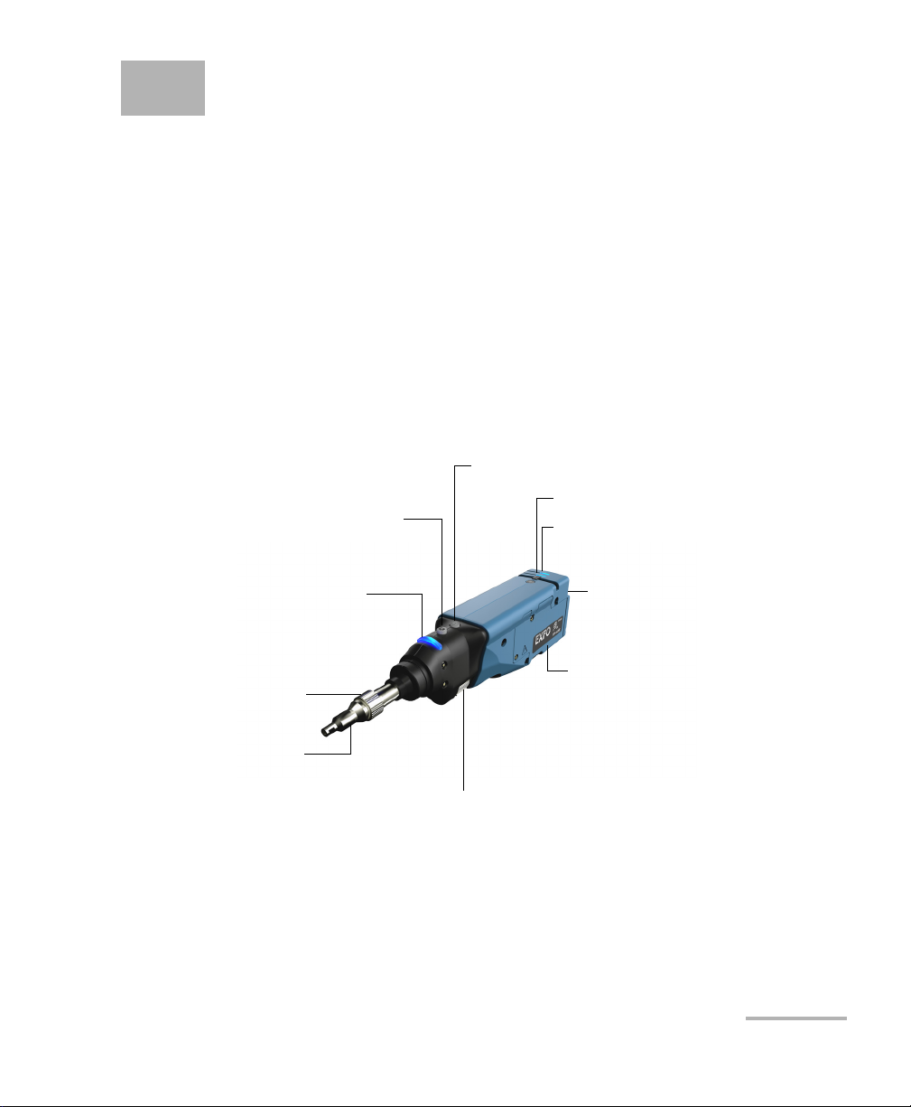
1 Introducing the FIP-400B Fiber
Status LED
Retaining nut
Focus
Magnification control
Capture control
Interchangeable
adapter tips
Micro USB adapter
connector
Battery compartment door
Battery LED
Wi-Fi LED
Inspection Probe and
ConnectorMax2 Mobile
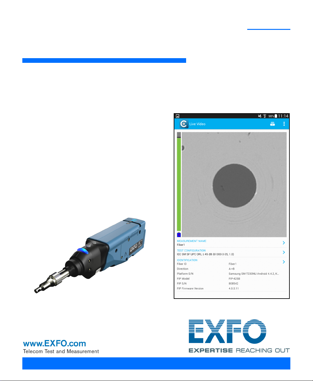
The FIP-400B Fiber Inspection Probe is a portable video microscope used
to inspect fiber ends. Unlike traditional microscopes, the FIP-400B
facilitates the examination of patchcord connectors and also hard-to-reach
connectors on the back of patch panels and bulkhead adapters.
Probe
The FIP-400B is designed to be an intuitive, easy-to-use piece of
equipment. This video microscope is used for inspecting fiber ends.
Fiber Inspection Probe 1
The focus knob can be turned in either direction to focus the image.
The magnification control button allows you to shift between three
levels of magnification. When pressed for one second, it activates the
auto focus.
Page 10

Introducing the FIP-400B Fiber Inspection Probe and ConnectorMax2 Mobile
Probe
The capture control button allows you to capture an image, perform an
analysis, or return to the Live Video mode.
The retaining nut holds tips securely in place, ensuring they are always
fastened in the correct position.
The status LED gives you information about the probe or the analysis
results.
The interchangeable adapter tips give you the possibility to use various
tips depending on the type of connector you are inspecting.
The micro USB adapter connector recharges the battery of the probe
when it is low. You can recharge the battery with the provided USB
cable and the adapter/charger that you connect to a power outlet. You
can also use the provided USB cable alone that you connect to a USB
port of a computer.
When the probe is connected to a power outlet or to a USB port, it still
works via Wi-Fi.
The battery compartment door is for battery replacement.
The probe comes equipped with a protective cap that fits over basic tips;
therefore, you do not need to remove the tip before putting the cap on.
2 FIP-400B
Page 11
Introducing the FIP-400B Fiber Inspection Probe and ConnectorMax2 Mobile
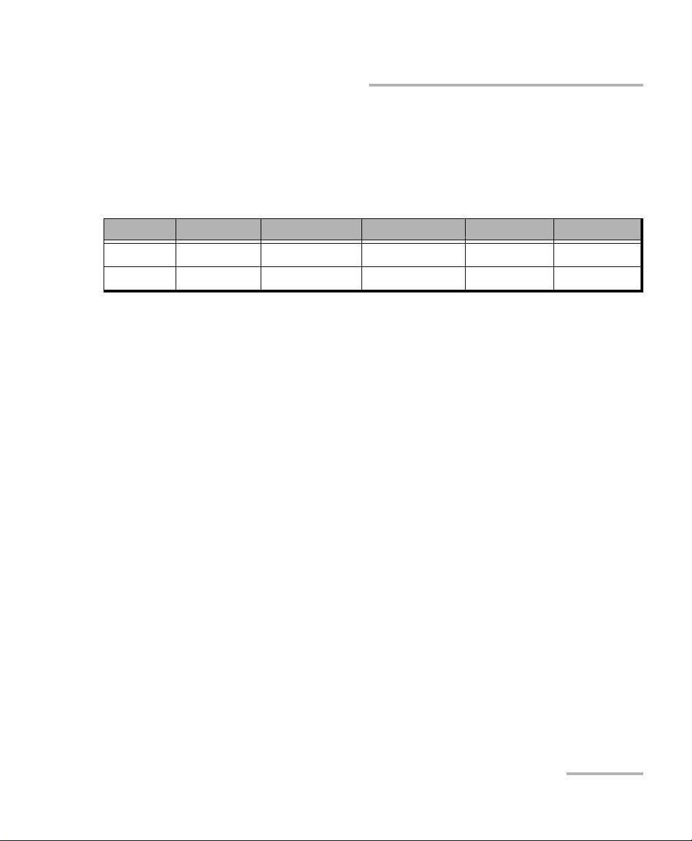
Available Models
Available Models
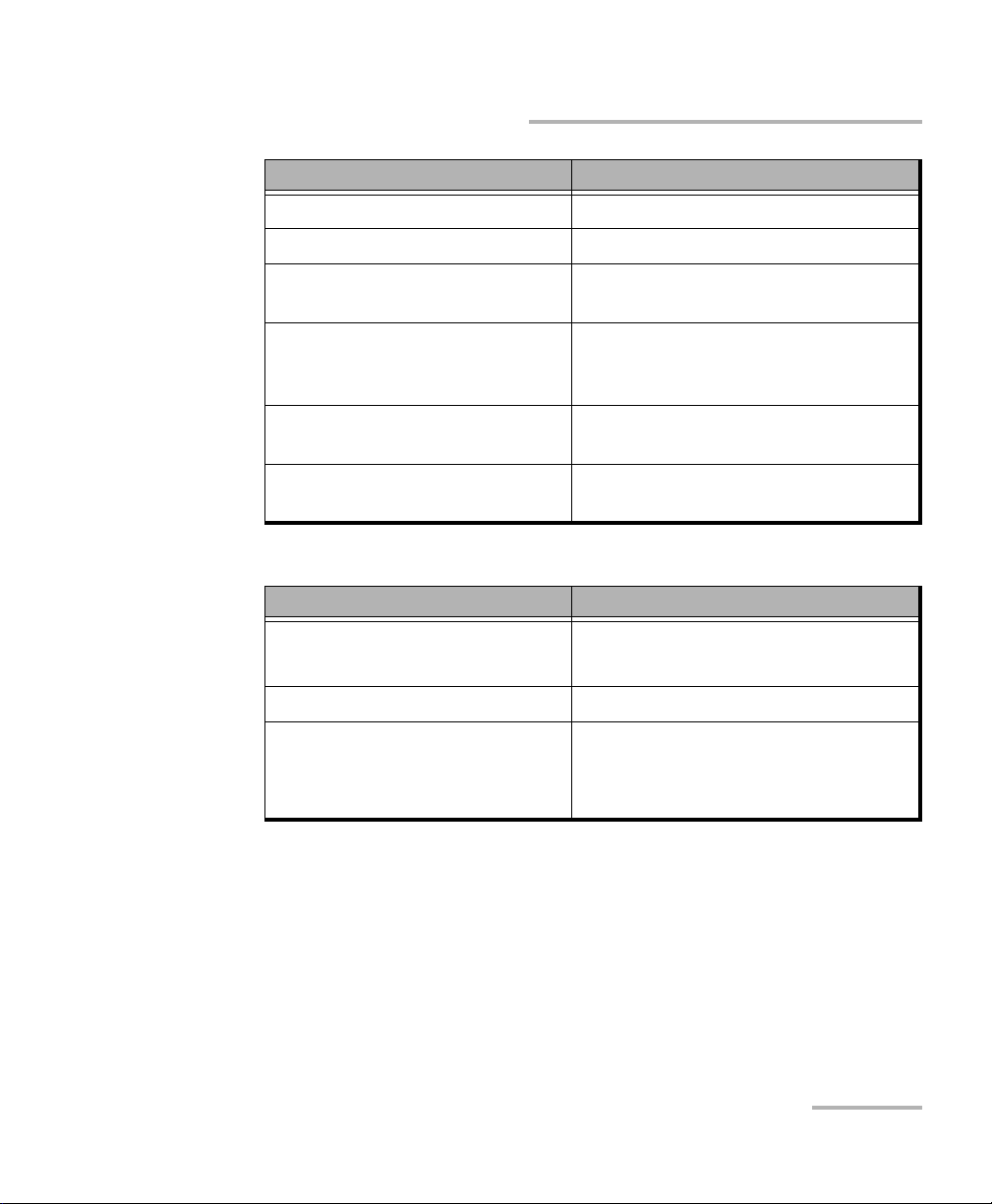
The features available for your probe are automatically detected when you
connect it to your smart device. The table below shows which feature is
available for each model.
Models Inspection Auto analysis Auto centering Auto focus Auto capture
FIP-425B X X X - -
FIP-435B X X X X X
Note: When the internal temperature of the FIP-435B is too low, the probe
performs a warm-up that can last up to a minute.
Probe Tips
The FIP-400B comes with two interchangeable tips included in two
different packages (UPC or APC). Additional models are also available.
UPC package:
FIPT-400-FC-SC: FC-SC Bulkhead tip
FIPT-400-U25M: Universal patchcord tip (2.5 mm ferrule)
APC package:
FIPT-400-SC-APC: SC APC tip for bulkhead adapter
FIPT-400-U25MA: Universal patchcord tip for 2.5 mm ferrules
Other tip models are available for various bulkhead adapters and
patchcord connectors. For more information about tips and their use, see
the Fiber Inspection Probe Tip Compatibility Chart on page 85, or visit the
EXFO Web site.
Fiber Inspection Probe 3
Page 12
Introducing the FIP-400B Fiber Inspection Probe and ConnectorMax2 Mobile
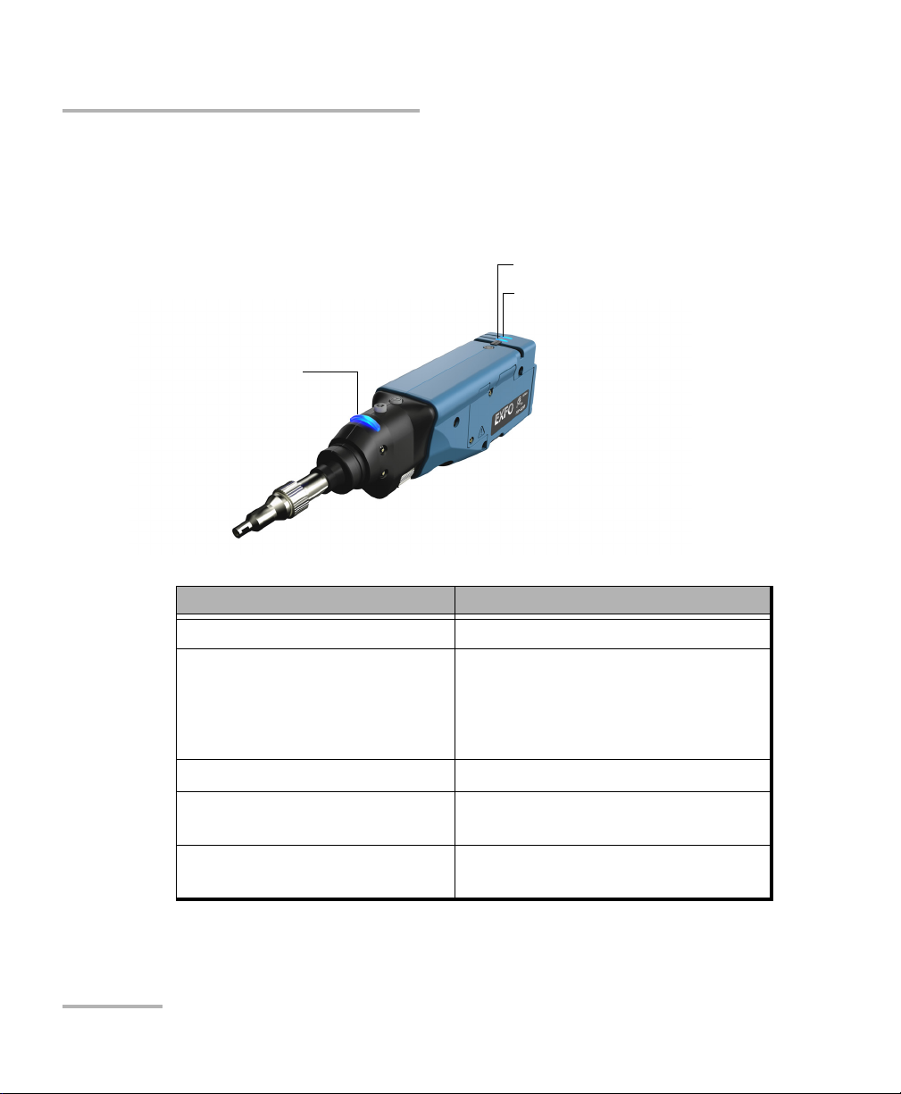
Status LED
Battery LED
Wi-Fi LED
LED Indicators
LED Indicators
The LED located on the probe gives you information about the probe or the
analysis results.
Status LED Status
Flashing blue Processing in progress
Flashing red
There is a problem with the probe.
Follow the instructions on screen.
The auto focus is in timeout
There is an analysis error
Blue The probe is ready and operational
Red In Capture mode, current FIP result
status is Fail
Green In Capture mode, current FIP result
status is Pass
4 FIP-400B
Page 13
Introducing the FIP-400B Fiber Inspection Probe and ConnectorMax2 Mobile
LED Indicators
Battery LED Status
Flashing blue USB connected, battery charging
Blue USB connected, battery fully charged
Red Battery error (only visible when
connected to a USB cable)
Flashing yellow USB connected, battery not charging
because the battery temperature does
not allow the battery to charge
Yellow USB not connected, critical battery
level
Not lit USB not connected, battery above low
level
Wi-Fi LED Status
Blue Ready to transmit
Wireless transmission in progress
Red Transmission error
Not lit
Probe is off
OR
Probe is initializing
Fiber Inspection Probe 5
Page 14
Introducing the FIP-400B Fiber Inspection Probe and ConnectorMax2 Mobile
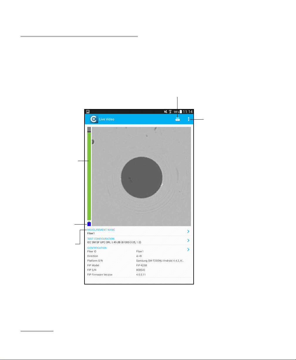
Battery status
Name of the file
resulting from the
autonaming
Archive icon
User Preferences
Can be found in
the menu button
depending on the
smart device used.
Auto focus
ConnectorMax2 Mobile Software
ConnectorMax2 Mobile Software
ConnectorMax2 Mobile is the application used to view the fiber
inspections. You can also use specific test configurations and analyze the
fibers automatically upon capturing a picture.
6 FIP-400B
Page 15
Introducing the FIP-400B Fiber Inspection Probe and ConnectorMax2 Mobile
Conventions
Conventions
Before using the product described in this guide, you should understand
the following conventions:
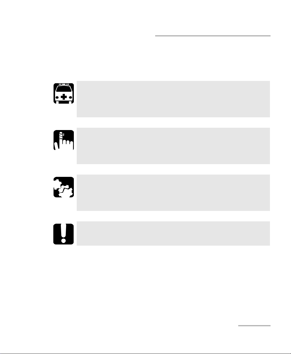
WARNING
Indicates a potentially hazardous situation which, if not avoided,
could result in death or serious injury. Do not proceed unless you
understand and meet the required conditions.
CAUTION
Indicates a potentially hazardous situation which, if not avoided,
may result in minor or moderate injury. Do not proceed unless you
understand and meet the required conditions.
CAUTION
Indicates a potentially hazardous situation which, if not avoided,
may result in component damage. Do not proceed unless you
understand and meet the required conditions.
IMPORTANT
Refers to information about this product you should not overlook.
Note: The appearance and the orientation (portrait or landscape) of the
application may vary depending on the smart device used.
Fiber Inspection Probe 7
Page 16

Page 17
2 Safety Information
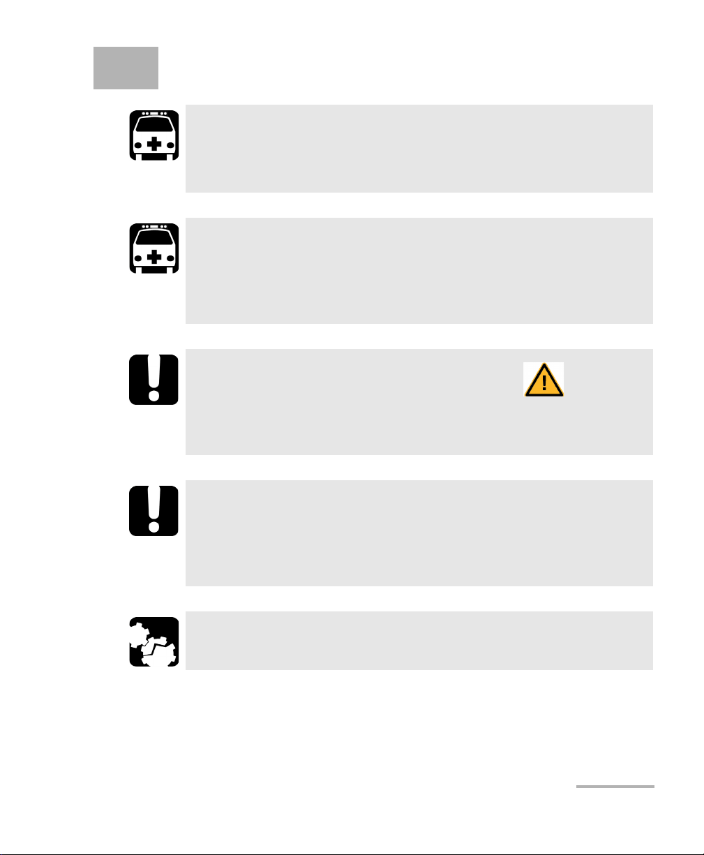
WARNING
Do not install or terminate fibers while a light source is active.
Never look directly into a live fiber and ensure that your eyes are
protected at all times.
WARNING
The use of controls, adjustments and procedures, namely for
operation and maintenance, other than those specified herein may
result in hazardous radiation exposure or impair the protection
provided by this unit.
IMPORTANT
When you see the following symbol on your unit , make sure
that you refer to the instructions provided in your user
documentation. Ensure that you understand and meet the required
conditions before using your product.
IMPORTANT
Other safety instructions relevant for your product are located
throughout this documentation, depending on the action to
perform. Make sure to read them carefully when they apply to your
situation.
CAUTION
Do not use the fiber probe outdoors in wet locations.
Fiber Inspection Probe 9
Page 18
Safety Information
Other Safety Symbols on Your Unit
Other Safety Symbols on Your Unit
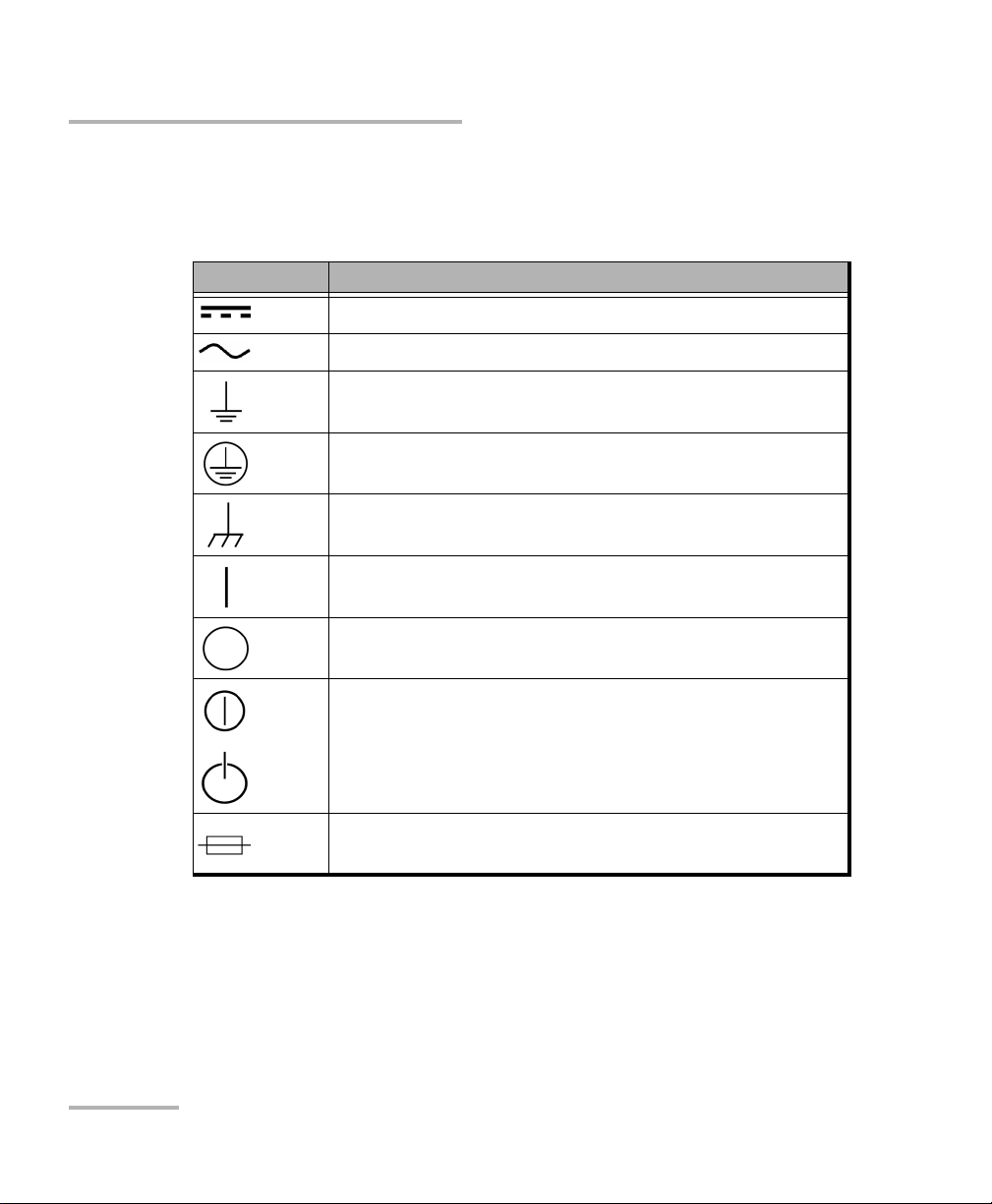
One or more of the following symbols may also appear on your unit.
Symbol Meaning
Direct current
Alternating current
The unit is equipped with an earth (ground) terminal.
The unit is equipped with a protective conductor terminal.
The unit is equipped with a frame or chassis terminal.
On (Power)
Off (Power)
OR On/Off (Power)
Fuse
10 FIP-400B
Page 19

Safety Information
Electrical Safety Information
Electrical Safety Information
If you need to ensure that the unit is completely turned off, disconnect the
power cable and remove the battery.
WARNING
Use the external electrical power supply indoors only.
Position the unit so that the air can circulate freely around it.
Operation of any electrical instrument around flammable gases
or fumes constitutes a major safety hazard.
To avoid electrical shock, do not operate the unit if any part of
the outer surface (covers, panels, etc.) is damaged.
Only authorized personnel should carry out adjustments,
maintenance or repair of opened units under voltage. A person
qualified in first aid must also be present. Do not replace any
components while the power cable and battery are connected.
Capacitors inside the unit may be charged even if the unit has
been disconnected from its electrical supply.
Use only the listed and certified AC adapter/charger provided by
EXFO with your unit. It provides reinforced insulation between
primary and secondary, and is suitably rated for the country
where the unit is sold.
Fiber Inspection Probe 11
Page 20
Safety Information
Electrical Safety Information
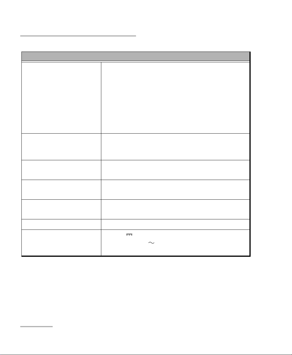
Equipment Ratings
Tem pe ra tu re
Operation
Unit powered by batteries: -10 °C to 40 °C
(14 °F to 104 °F)
Unit connected to USB adapter: 0 °C to 40 °C
(32 °F to 104 °F)
Storage Unit without batteries: -40 °C to 70 °C
(-40 °F to 158 °F)
Unit with batteries: -20 °C to 60 °C
(-4 °F to 140 °F)
Relative humidity
a
unit: 95 % non-condensing
USB adapter: 5 % to 95 % for storage and 8 % to 90 %
for operating temperature
Maximum operation altitude
Pollution degree
2000 m (6562 ft) (unit connected to USB adapter)
3000 m (9843 ft) (unit operated from batteries)
2 (unit connected to external power supply)
3 (unit operated from batteries)
b
Overvoltage category unit: I
AC adapter: II
Measurement category Not rated for measurement categories II, III, or IV
Input power
c
unit: 5 VDC; 1.8 A
USB adapter: 100 - 240 Vac; 50 Hz to 60 Hz;
0.4 A Max
a. Measured in 0 °C to 31 °C (32 °F to 87.8 °F) range, decreasing linearly to 50 % at 40 °C (104 °F).
b. Equipment must be normally protected against exposure to direct sunlight, precipitation and full wind
pressure.
c. Not exceeding ± 10 % of the nominal voltage.
12 FIP-400B
Page 21

3 Setting up Your Fiber
Inspection Probe and
ConnectorMax2 Mobile
When you receive your wireless probe, and before you start working, you
need to download the ConnectorMax2 Mobile application on your smart
device. The application is available for smart devices supporting
Android 4.2, mainly Samsung Galaxy Note 3 and 4, as well as Samsung
Galaxy Tab 4 with an 8-inch screen.
You can change various settings in ConnectorMax2 Mobile, such as the
automated file name or the way you want to share files with third party
applications. These settings are kept for future work sessions.
Preparing to Use the Mobile Application
Before you start working with your wireless probe, there are two steps to
perform.
You need to install ConnectorMax2 Mobile on your smart device.
IMPORTANT
The ConnectorMax2 Mobile application is available for free in
Google Play Store. You need to have a Google account to download
the application. For more information, refer to www.google.com.
Once the application is installed, you have to connect your wireless
probe by Wi-Fi.
When your wireless probe is connected, it is added to the list of the
available probes. It remains available for future tests.
Note: You need to have access to an external Wi-Fi network to install
ConnectorMax2 Mobile. The Wi-Fi needs to be set to ON on your smart
device.
Fiber Inspection Probe 13
Page 22

Setting up Your Fiber Inspection Probe and ConnectorMax2 Mobile
Connecting or Disconnecting the Wireless Probe
To install ConnectorMax2 Mobile:
1. Ensure you have access to an Internet connection.
2. Ta p th e Google Play Store icon.
3. In the Google Play Store (or Play Store) application, search for EXFO
or ConnectorMax2 Mobile.
4. Follow the instructions on-screen.
Once the ConnectorMax2 Mobile is installed, you can now activate the
wireless probe.
Connecting or Disconnecting the Wireless
Probe
When the ConnectorMax2 Mobile is installed on your smart device, you
have to connect your wireless probe by Wi-Fi. When your wireless probe is
connected it is added to the list of the available probes. It remains available
for future tests.
You have to disconnect the probe first if you want to perform the following:
work with another probe
use the probe with another smart device
share files with third-party applications
14 FIP-400B
Page 23
Setting up Your Fiber Inspection Probe and ConnectorMax2 Mobile
Connecting or Disconnecting the Wireless Probe
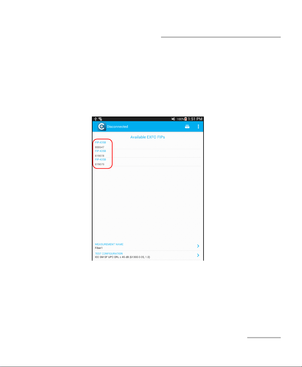
To connect the wireless probe:
1. Ensure the power saving mode is disabled on your smart device.
2. Turn on the probe by pressing the ON button.
3. Ensure the Wi-Fi is activated on your smart device.
4. Start the ConnectorMax2 Mobile application.
5. Select the wireless probe you want to work with.
Note: When a wireless probe is selected, the 3G, 4G and LTE communications are
disabled automatically.
Note: The probes are identified by their serial numbers and type.
Note: The probe can be selected from the Wi-Fi configuration on the smart
device.
Fiber Inspection Probe 15
Page 24
Setting up Your Fiber Inspection Probe and ConnectorMax2 Mobile
Connecting or Disconnecting the Wireless Probe
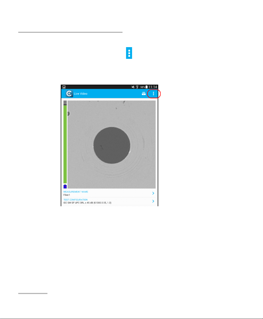
To disconnect the wireless probe:
1. From the main window, tap .
Note: Depending on the smart device you are using, the application settings can
be found in the menu button instead.
2. Select Disconnect probe.
16 FIP-400B
Page 25
Setting up Your Fiber Inspection Probe and ConnectorMax2 Mobile
Changing the Fiber Inspection Probe Tip
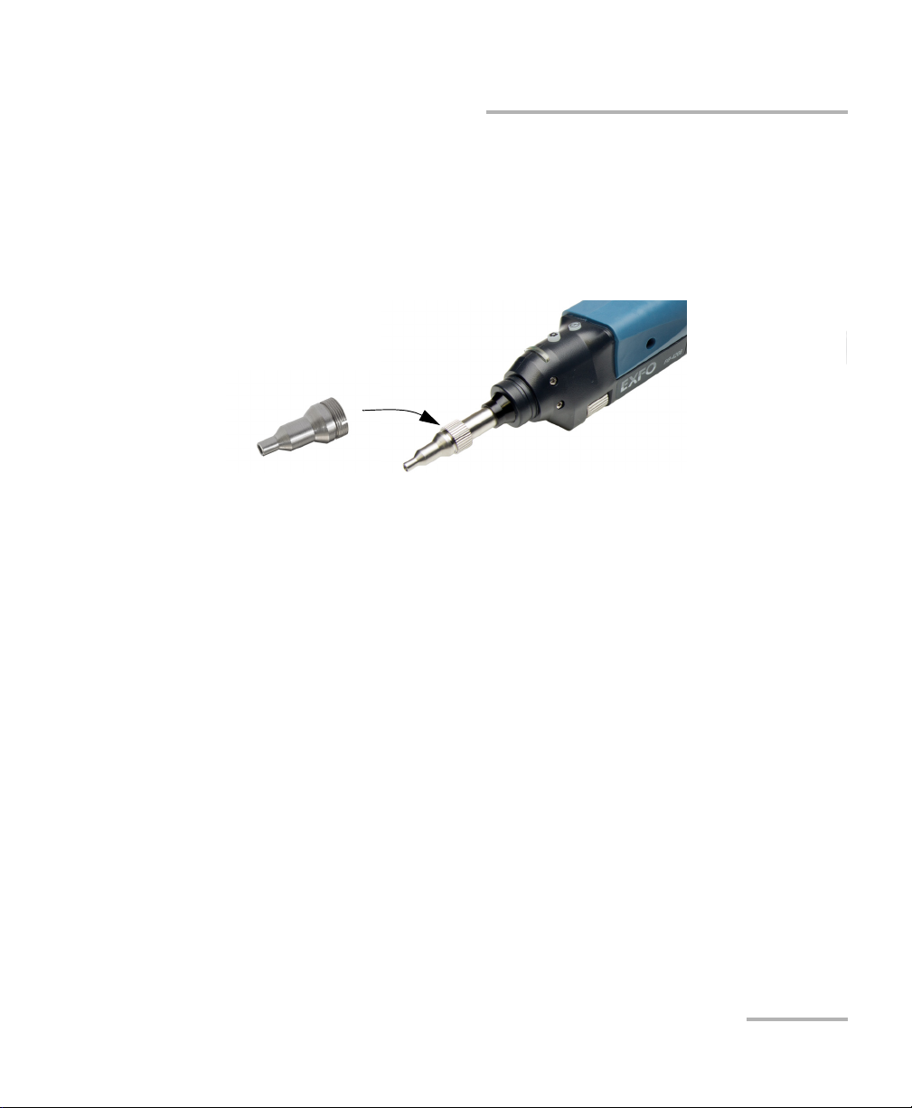
Changing the Fiber Inspection Probe Tip
You can use various tips depending on the type of connector you are
inspecting. For more information about tips you can use, see the Fiber
Inspection Probe Tip Compatibility Chart on page 85, or contact your
vendor for additional information.
To change a tip:
1. Untighten the tip’s retaining nut.
2. Remove the tip.
3. Insert a new tip.
4. Adjust the tip to the notch.
5. Retighten the retaining nut.
Fiber Inspection Probe 17
Page 26

Setting up Your Fiber Inspection Probe and ConnectorMax2 Mobile
Setting up Autonaming
Setting up Autonaming
The autonaming feature is useful to make a relevant naming scheme for
your tests. This also ensures that you do not overwrite files by mistake. You
can select which item goes in the file name, as well as the type of separator
you want to use in between.
A preview is available to show you the final output of the file name.
In Live Video mode, the autonaming parameters can be set. You will only
see the parameters for the current and next capture (when the test is done
but not saved yet), or for the next capture only (test is not done yet).
Otherwise, the parameters will not be displayed.
In Capture and Archive modes, it is possible to change the name of the file
without changing the settings.
18 FIP-400B
Page 27
Setting up Your Fiber Inspection Probe and ConnectorMax2 Mobile
Setting up Autonaming
To configure the automatic file naming:
1. From the main window, tap the at the end of the Identification row.
Note: You can also tap the at the end of the Measurement Name row.
Fiber Inspection Probe 19
Page 28
Setting up Your Fiber Inspection Probe and ConnectorMax2 Mobile
Setting up Autonaming
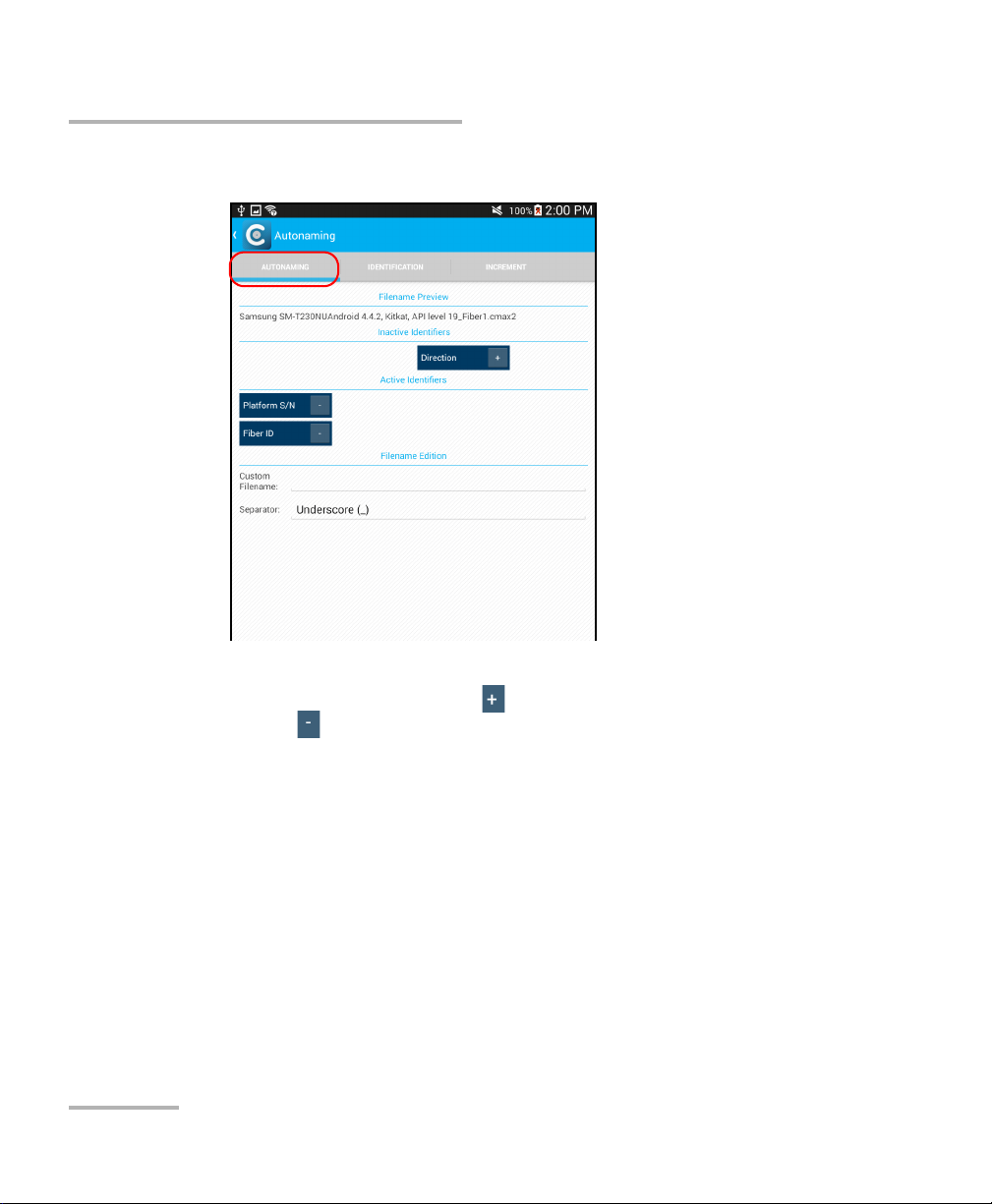
2. Select the Autonaming tab.
3. Move the identifiers from the Inactive Identifiers to the Active
Identifiers space by tapping . You can remove the identifiers by
tapping . You can also move the identifiers with the drag and drop
gesture.
Note: Only the identifiers with values are displayed.
4. Under Filename Edition, you can customize the information displayed
next to Custom Filename.
Note: You can edit information either with the virtual keyboard or with the
microphone. A microphone is part of the virtual keyboard on your smart
device.
20 FIP-400B
Page 29

Setting up Your Fiber Inspection Probe and ConnectorMax2 Mobile
Setting up Autonaming
5. If you want to select the separator in the automatic numbering section,
tap the line next to Separator.
5a. Navigate through the separators by scrolling through the words
that are greyed.
5b. Tap OK to confirm your choice.
6. Tap to confirm your new settings and to return to the main window.
The new settings will apply the next time you perform a capture.
Fiber Inspection Probe 21
Page 30
Setting up Your Fiber Inspection Probe and ConnectorMax2 Mobile
Setting up Identification
Setting up Identification
In order to have information on the tests to be performed, it is possible to
customize some fields such as the cable ID, the fiber ID, the location (A
and/or B), the Connector ID, or the Frame.
To configure the identification:
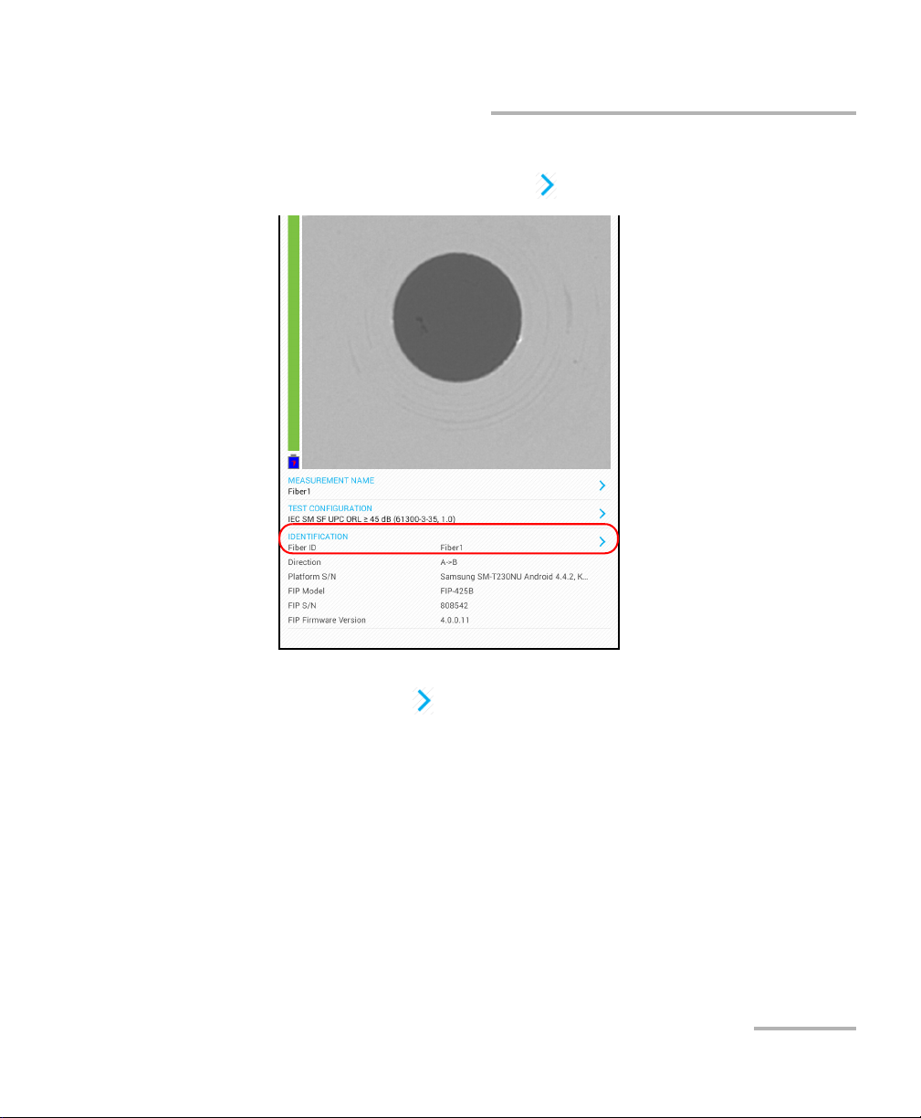
1. From the main window, tap the at the end of the Identification row.
Note: You can also tap the at the end of the Measurement Name row.
22 FIP-400B
Page 31

Setting up Your Fiber Inspection Probe and ConnectorMax2 Mobile
Setting up Identification
2. If necessary, select the Identification tab.
Fiber Inspection Probe 23
Page 32

Setting up Your Fiber Inspection Probe and ConnectorMax2 Mobile
Setting up Identification
3. Enter all the information as follows:
3a. Locate the row corresponding to the identifier that you want to
modify.
3b. Tap on the line next to the identifier that you want to modify and
enter the information.
Note: You can edit information either with the virtual keyboard or with the
microphone. A microphone is part of the virtual keyboard on your smart
device.
4. Tap to confirm your new settings and to return to the main window.
The new settings will apply the next time you perform a capture.
Note: Some identifiers are also displayed as read-only information.
24 FIP-400B
Page 33

Setting up Your Fiber Inspection Probe and ConnectorMax2 Mobile
Setting up the Increment
Setting up the Increment
The file name is made of one or more static parts (alphanumeric) and one
or more variable parts (numeric) that will be incremented or
decremented, according to your selection, as follows:
If you choose incrementation... If you choose decrementation...
Variable part increases until it
reaches the highest possible value
with the selected number of digits,
then restarts at 1.
Note: To decrement values, the start number must be higher than the stop
number.
The file name can be incremented using one or more identifiers. Selecting
a single identifier will follow the incrementation (or decrementation) value
you have set.
When selecting more than one identifier, the latter appear sequentially in
the order that you have set, and the incrementation will start with the last
item in the list (the one with the farthest indentation). For example, if you
have a file name with the Location, Cable and Fiber identifiers, in that
order, the first item to be incremented is the Fiber identifier, then Cable,
then Location:
Location 1, Cable 1, Fiber 1
Location 1, Cable 1, Fiber 2
Location 1, Cable 2, Fiber 1
Variable part decreases until it
reaches 1, then restarts at the highest
possible value with the selected
number of digits.
Location 1, Cable 2, Fiber 2
and so forth.
Fiber Inspection Probe 25
Page 34

Setting up Your Fiber Inspection Probe and ConnectorMax2 Mobile
Setting up the Increment
After a result is saved, you have to return to the Live Video mode so that the
application prepares the next file name by incrementing (or decrementing)
the suffix.
Note: If you choose not to save a particular file, the suggested file name remains
available for the next capture. This applies to all type of connectors.
You can select the number of digits displayed for the incremented or
decremented values.
Select "#" if you want to keep the value exactly in the same format as
defined in the start and stop values. If a value is to be incremented from 1
to 10, it becomes 1, 2, 3, ... 9, 10. One "#" is the default format.
Select two, three, or four "#" if you want all values to be expressed with the
same number of digits. The application fills the empty spaces with zeros
before the increment or decrement to ensure the appropriate format is
displayed. For example, if you select two "#" and the value is to be
incremented from 1 to 10, it becomes 01, 02, 03, ... 09, 10.
26 FIP-400B
Page 35

Setting up Your Fiber Inspection Probe and ConnectorMax2 Mobile
Setting up the Increment
To configure the incrementation:
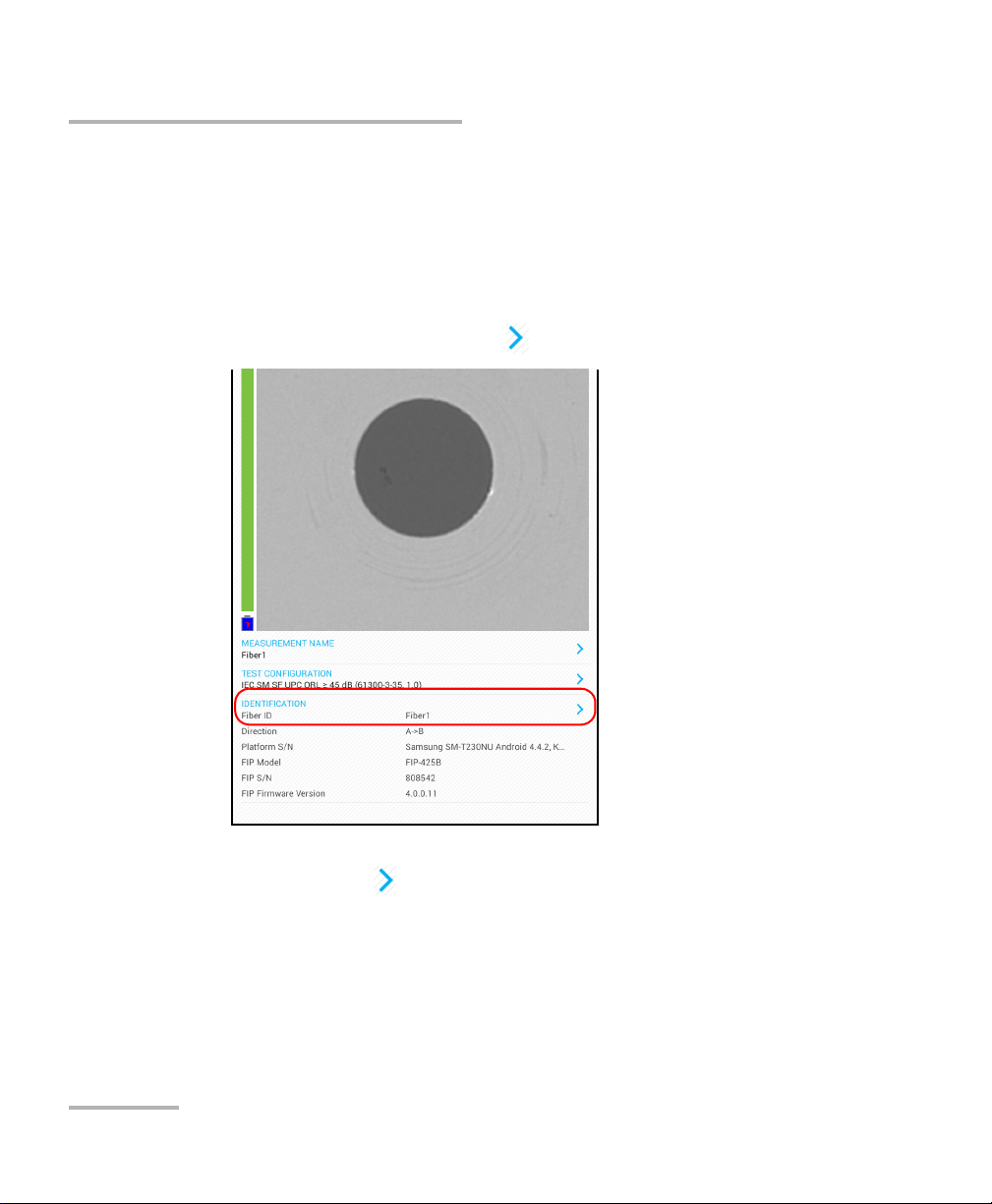
1. From the main window, tap the at the end of the Identification row.
Note: You can also tap the at the end of the Measurement Name row.
Note: Setting up the increment is only possible in Live Video mode.
Fiber Inspection Probe 27
Page 36

Setting up Your Fiber Inspection Probe and ConnectorMax2 Mobile
Setting up the Increment
2. If necessary, select the Increment tab.
3. Move the increments from the Inactive Increments to the Active
Increments space by tapping . You can remove the identifiers by
tapping . You can also move the identifiers with the drag and drop
gesture.
Note: Only the identifiers with values are displayed.
4. When an increment is moved to the Active Increments, enter the start,
stop and increment values as desired.
Note: To decrement values, the start number must be higher than the stop
number.
5. Tap to confirm your new settings and to return to the main window.
The new settings will apply the next time you perform a capture.
28 FIP-400B
Page 37

Setting up Your Fiber Inspection Probe and ConnectorMax2 Mobile
Setting Up Auto Capture
Setting Up Auto Capture
Note: The auto capture is a feature available for FIP-435B probes only.
As soon as the application detects that you are working in Live Video
mode, the feature is enabled in the Application Settings, and if the focus
level is acceptable, a capture is made automatically. This is known as the
auto capture.
Note: The auto capture is possible only in high magnification.
To enable the auto capture:
1. From the main window, tap .
Note: Depending on the smart device you are using, the application settings can
be found in the menu button instead.
Fiber Inspection Probe 29
Page 38

Setting up Your Fiber Inspection Probe and ConnectorMax2 Mobile
Setting Up Auto Capture
2. Select Application Settings.
3. Under Probe, active the ON button next to Auto capture.
4. Tap to return to the main window.
30 FIP-400B
Page 39

Setting up Your Fiber Inspection Probe and ConnectorMax2 Mobile
Selecting Test Configurations
Selecting Test Configurations
If you are testing single fibers, you can select specific test configurations
according to the type of fiber you are analyzing, the connector type or the
type of anomaly you are looking for.
When working with the smart device, you can hide some test
configurations with the eye icon.
Note: You cannot hide the current test configuration.
To select a test configuration:
1. From the main window, tap the at the end of the Tes t
Configuration row.
Fiber Inspection Probe 31
Page 40

Setting up Your Fiber Inspection Probe and ConnectorMax2 Mobile
Selecting Test Configurations
2. Select the configuration you want to use in the list of available choices
and tap the On or Off button.
Note: If you want to select more than one test configurations at a time, press and
hold the desired test configurations.
Note: You cannot select the current test configuration.
3. Tap to return to the main window.
32 FIP-400B
Page 41

Setting up Your Fiber Inspection Probe and ConnectorMax2 Mobile
Selecting Test Configurations
To show or hide test configurations:
1. From the main window, tap the at the end of the Tes t
Configuration row.
Fiber Inspection Probe 33
Page 42

Setting up Your Fiber Inspection Probe and ConnectorMax2 Mobile
Selecting Test Configurations
2. In the Test Configuration window, tap the test configuration you want
to hide.
Note: If you want to select more than one test configurations at a time, press and
hold the desired test configurations.
Note: You cannot select the current test configuration.
34 FIP-400B
Page 43

Setting up Your Fiber Inspection Probe and ConnectorMax2 Mobile
Selecting Test Configurations
3. Tap the icon to hide the test configurations.
4. Tap the icon to show all test configurations.
5. Tap to return to the main window.
Fiber Inspection Probe 35
Page 44

Setting up Your Fiber Inspection Probe and ConnectorMax2 Mobile
Modifying the File Format
Modifying the File Format
The data that can be shared with third-party applications are measurement
files (.cmax2) and images (.png).
By default, you will be prompted to select the file format with which you
want to work.
To modify the file format:
1. From the main window, tap .
Note: Depending on the smart device you are using, the application settings can
be found in the menu button instead.
2. Select Application Settings.
36 FIP-400B
Page 45

Setting up Your Fiber Inspection Probe and ConnectorMax2 Mobile
Modifying the File Format
3. Under Sharing, tap Preferred file format.
4. Navigate through the preferred file format by scrolling through the
words that are greyed.
5. Ta p OK to confirm your choice.
6. Tap to return to the main window.
Fiber Inspection Probe 37
Page 46

Setting up Your Fiber Inspection Probe and ConnectorMax2 Mobile
Selecting the Sharing Application
Selecting the Sharing Application
Third-party applications, such as Google Drive and DropBox, are useful
when you want to share measurement files with other users. For more
information, see Transferring Results With Third-Party Applications on
page 60.
By default, you will be prompted to select the application with which you
want to work. You can configure the unit to always start your favorite
application directly instead.
To select the sharing application:
1. From the main window, tap .
Note: Depending on the smart device you are using, the application settings can
be found in the menu button instead.
38 FIP-400B
Page 47

Setting up Your Fiber Inspection Probe and ConnectorMax2 Mobile
Selecting the Sharing Application
2. Select Application Settings.
3. Under Sharing, tap Preferred application.
4. Navigate through the preferred application by scrolling through the
words that are greyed.
5. Ta p OK to confirm your choice.
6. Tap to return to the main window.
Fiber Inspection Probe 39
Page 48

Setting up Your Fiber Inspection Probe and ConnectorMax2 Mobile
Sharing Data When No Connection Is Available
Sharing Data When No Connection Is Available
By default, the application will prompt you to define the action to perform
when there is no 3G, 4G or Wi-Fi external connection available. You can let
the application buffer the files, or you can modify the wireless or mobile
settings and try sharing the files again.
If the FIP measurements are buffered, the application will transmit them
sequentially as soon as the network is available again.
Note: You need to disconnect the probe before trying to share data. Otherwise,
the data will be buffered anyway.
If you prefer not to be prompted each time no connection is available, you
can configure the application to always send the files to the buffer directly
instead.
40 FIP-400B
Page 49

Setting up Your Fiber Inspection Probe and ConnectorMax2 Mobile
Sharing Data When No Connection Is Available
To share data when no connection is available:
1. From the main window, tap .
Note: Depending on the smart device you are using, the application settings can
be found in the menu button instead.
2. Select Application Settings.
Fiber Inspection Probe 41
Page 50

Setting up Your Fiber Inspection Probe and ConnectorMax2 Mobile
Sharing Data When No Connection Is Available
3. Under Sharing, tap Preferred behavior when no connection is
available.
4. Navigate through the preferred behavior by scrolling through the words
that are greyed.
5. Ta p OK to confirm your choice.
6. Tap to return to the main window.
42 FIP-400B
Page 51

Setting up Your Fiber Inspection Probe and ConnectorMax2 Mobile
Restoring to Default Settings
Restoring to Default Settings
At any time, you can restore to default settings in your smart device. The
Restore default settings button restores all values that were changed in
the Application Settings.
To restore to default settings:
1. From the main window, tap .
Note: Depending on the smart device you are using, the application settings can
be found in the menu button instead.
2. Select Application Settings.
Fiber Inspection Probe 43
Page 52

Setting up Your Fiber Inspection Probe and ConnectorMax2 Mobile
Restoring to Default Settings
3. Ta p th e Restore Default Settings button.
4. Tap to return to the main window.
44 FIP-400B
Page 53

4 Inspecting Fiber Ends
Viewing the fiber inspection is done using ConnectorMax2 Mobile. You can
start the application before or after connecting the probe, and the view
on-screen will be automatically updated.
WARNING
Never look directly into a live fiber. It could cause serious eye
damage. Always use your FIP-400B Fiber Inspection Probe.
Inspecting Fiber Ends
When you connect the FIP-400B Fiber Inspection Probe to your smart
device, you can view and inspect fiber ends right away. This direct viewing
mode is known as the Live Video mode.
Note: When the internal temperature of the FIP-435B is too low, the probe
performs a warm-up that can last up to a minute.
You can also capture images of your inspections to save them for future
analyses. This is known as the Capture mode.
A digital watermark is added to the images generated by the application.
Fiber Inspection Probe 45
Page 54

Inspecting Fiber Ends
Inspecting Fiber Ends
The focus indicator, which is displayed in the left part of the main window,
indicates whether the current view is optimized for a capture. A green
indicator shows a picture that can be captured and analyzed. Analysis will
be more difficult with a yellow indicator, and impossible with a red
indicator. A vertical black bar displays the peak focus level.
Note: The peak focus level is shown only when the auto focus sequence is
complete.
For more information on analysis, see Analyzing Captures on page 56.
46 FIP-400B
Page 55

Inspecting Fiber Ends
Inspecting Fiber Ends
To inspect fiber ends (single fiber) in Live Video mode:
1. Install a probe tip (see Changing the Fiber Inspection Probe Tip on
page 17).
2. Insert the fiber into the probe tip.
3. Start ConnectorMax2 Mobile if it is not already started.
4. Ensure to configure the automatic file naming (see Setting up
Autonaming on page 18).
5. Depending on the probe you are using, proceed as follows:
If you have an FIP-425B, the auto analysis and the auto centering
(enabled by default) adjust automatically.
If you have an FIP-435B, the auto analysis, the auto centering, the
auto focus (all enabled by default), and the auto capture adjust
automatically.
For more information, see Analyzing Captures on page 56.
Note: With your fingers, you can stretch to zoom in on the image of the connector
on screen and pinch to zoom out of it.
6. If the fiber end is dirty, remove it from the probe, clean it and
reinspect it.
7. Once you are satisfied with the inspection, when in high magnification
level, press and hold the image of the connector on screen.
OR
Press the Fiber Inspection Probe handset button.
8. Go to the next connector or close the application.
Fiber Inspection Probe 47
Page 56

Inspecting Fiber Ends
Saving Files
Saving Files
In Capture mode, you can save the acquisition files manually for future
reference.
You can also set ConnectorMax2 Mobile so that it saves the capture
automatically only if the result is Pass, only if the result is Fail, or regardless
of the status. When it is not possible to save a file, the application displays a
message.
All the files (saved manually or automatically) are sent to the following
folder: Storage/Emulated/0/Documents/EXFO/cmax2. For smart devices
supporting Android 4.4 (kit kat) and above, the files are sent to the
following folder: /Android/data/com.exfo.cmax2.mobile.android/files/.
Note: When you return to the Live Video mode, your file name structure will be
automatically incremented or decremented so that you do not overwrite
your work.
48 FIP-400B
Page 57

Inspecting Fiber Ends
To s av e a fi l e:
1. In Live Video mode, press and hold the image on screen.
2. In Capture mode, tap .
Saving Files
Fiber Inspection Probe 49
Page 58

Inspecting Fiber Ends
Saving Files
To save file automatically:
1. From the main window, tap .
Note: Depending on the smart device you are using, the application settings can
be found in the menu button instead.
2. Select Application Settings.
50 FIP-400B
Page 59

Inspecting Fiber Ends
Saving Files
3. Under Saving, select the type of auto save you want to use by
activating the ON button.
4. Tap to return to the main window.
Fiber Inspection Probe 51
Page 60

Inspecting Fiber Ends
Managing Files
Managing Files
You can open captured files directly from the smart device to view them.
All saved measurements are available in Archive mode. The application
scans the smart device periodically and store the .cmax2 files here:
Storage/Emulated/0/Documents/EXFO/cmax2. For smart devices
supporting Android 4.4 (kit kat) and above, the files are sent to the
following folder: /Android/data/com.exfo.cmax2.mobile.android/files/.
You can also delete unwanted files. By default, all files are highlighted but
you can unselect the files you want to keep by pressing and holding the
screen. Otherwise, all files will be deleted.
To share files, see Transferring Results With Third-Party Applications on
page 60.
The .cmax2 files, when saved with the ConnectorMax 2 smart device, are
compatible with any EXFO applications.
To o pe n a fi le :
1. From the main window, tap .
52 FIP-400B
Page 61

2. In the Archive window, select a file.
Inspecting Fiber Ends
Managing Files
3. Tap the selected file to open it.
Fiber Inspection Probe 53
Page 62

Inspecting Fiber Ends
Managing Files
To delete a file:
1. From the main window, tap .
54 FIP-400B
Page 63

2. In the Archive window, tap .
Inspecting Fiber Ends
Managing Files
3. By default, all files are highlighted but you can unselect the files you
want to keep by pressing and holding the screen.
IMPORTANT
All highlighted files will be deleted. Ensure to unselect the files you
want to keep.
4. Tap to delete the file.
Fiber Inspection Probe 55
Page 64

Inspecting Fiber Ends
Analyzing Captures
Analyzing Captures
With the capture analysis option (FIP-425B and FIP-435B), you can perform
automated pass/fail analyses according to the criteria you have set.
Depending on the fiber probe that you have, you may have access to the
following features:
Auto centering: displays the fiber in the middle of the image. It is
compatible with all connector types and fibers with a cladding of
125 μm. The auto centering is enabled only in high magnification.
Working with the auto centering feature can be useful with standard
connectors.
Auto focus: focuses on the connector image. It is enabled only in high
magnification. The auto focus is only possible in Live Video mode, and
if the focus is not done manually. It starts automatically when you insert
an optical fiber connector. For more information, see Fiber Inspection
Probe Tip Compatibility Chart on page 85.
Auto capture: is possible with an acceptable focus level. It is enabled if
the auto centering and auto focus are activated. The auto capture is
possible only in high magnification. For more information, see Setting
Up Auto Capture on page 29.
Auto analysis: displays 4 inspection zones: core, cladding, adhesive,
and contact. It is enabled only in high magnification.
The analysis results are available as soon as you press and hold your finger
on the image on-screen, when you press the capture button on the probe,
or when the auto capture feature is selected. For more information, see
Setting Up Auto Capture on page 29.
The global status is displayed in the upper right part of the window after an
analysis. The Results are displayed when a capture is made. When you are
ready to inspect another fiber, you have to return to the Live Video mode
first.
The results are available as an image or in a detailed table.
56 FIP-400B
Page 65

Inspecting Fiber Ends
Analyzing Captures
The Image shows the snapshot of the fiber when you captured it. You
can see all the anomalies that have been detected.
The overlay shows the status of the analysis, the status per zone, the
analysis zones, any anomaly (defects, scratches) found on the fiber
endface, and the global status in the upper right part of the main
window. The color of the circles shows the status of the analysis zone:
Green: pass
Blue: no analysis was performed or the function is disabled
Red: fail
Fiber Inspection Probe 57
Page 66

Inspecting Fiber Ends
Analyzing Captures
By default, the overlay is shown after an analysis, but you can hide it by
tapping the image on screen.
The Results show detailed information for scratches and defects
detected in each test zone and the corresponding test status.
58 FIP-400B
Page 67

Inspecting Fiber Ends
Analyzing Captures
To view the results:
1. In Live Video mode, press and hold your finger on the screen.
2. In Capture mode, tap the at the end of the Inspection Results row.
OR
Tap the pass or fail icon located on the upper right part of the main
window.
3. From the Inspection Results window, tap to return to the Capture
window.
Fiber Inspection Probe 59
Page 68

Inspecting Fiber Ends
Transferring Results With Third-Party Applications
Transferring Results With Third-Party
Applications
Third-party applications, such as Google Drive and DropBox, are useful
when you want to share measurement files with other users. The data that
can be shared are measurement files (.cmax2) and images (.png). The
third-party applications allow you to delete files also.
By default, you will be prompted to select the application with which you
want to work. If you prefer, you can configure the unit to always start your
favorite application directly instead (see Selecting the Sharing Application
on page 38).
It is possible to share the FIP measurements in Capture mode and in
Archive modes only. The Live Video mode does not allow it.
When there is no 3G, 4G or Wi-Fi external connection available, the
application buffers the FIP measurements that need to be shared. As soon
as the network is available, the application transmits the data sequentially.
You need to disconnect the probe first if you want to share data with the
smart device. Otherwise, the application buffers the FIP measurements.
IMPORTANT
If you want to transfer results with the DropBox third-party
application, you need to open a DropBox account first.
60 FIP-400B
Page 69

Inspecting Fiber Ends
Transferring Results With Third-Party Applications
To transfer results with third-party applications:
1. Ensure the Wi-Fi is activated on your smart device.
2. Ensure you are connected to a Wi-Fi network.
3. From the main window, tap .
Fiber Inspection Probe 61
Page 70

Inspecting Fiber Ends
Transferring Results With Third-Party Applications
4. In the Archive window, select the measurement files you want to share
by pressing and holding your finger on the screen.
62 FIP-400B
Page 71

Inspecting Fiber Ends
Transferring Results With Third-Party Applications
5. Ta p .
6.
Select the type of file (.cmax2 or .png) you want to share.
7.
Select the third-party application you want to work with (Google Drive
or Drop Box for example).
8. Follow the instructions on-screen.
Fiber Inspection Probe 63
Page 72

Page 73

5 Maintenance
General Maintenance
To help ensure long, trouble-free operation:
Always inspect fiber-optic connectors before using them and clean
them if necessary.
Keep the unit free of dust.
Clean the unit casing with a cloth slightly dampened with water.
Store unit at room temperature in a clean and dry area. Keep the unit
out of direct sunlight.
Avoid high humidity or significant temperature fluctuations.
Avoid unnecessary shocks and vibrations.
If any liquids are spilled on or into the unit, turn off the power
immediately, disconnect from any external power source, remove the
batteries and let the unit dry completely.
The use of controls, adjustments and procedures, namely for
operation and maintenance, other than those specified herein may
result in hazardous radiation exposure or impair the protection
provided by this unit.
WARNING
Recycling and Disposal (Applies to European Union Only)
For complete recycling/disposal information as per European Directive
WEEE 2012/19/UE, visit the EXFO Web site at www.exfo.com/recycle.
Fiber Inspection Probe 65
Page 74

Maintenance
Recharging the Battery
Recharging the Battery
The battery in your Fiber Inspection Probe is a Li-ion polymer battery with
three-cell format. The charge status is shown with the LEDs on the Fiber
Inspection Probe. The ConnectorMax2 Mobile software application also
indicates the charge status.
Only charge the battery with the USB cable and adapter/charger
provided by EXFO with your unit.
You can purchase a new battery from EXFO.
The battery is not charged at the factory. You must fully charge
CAUTION
IMPORTANT
it before using the unit for the first time. The battery is fully
charged after a few hours or when the battery LED indicator
stops flashing. The charge cycle starts and stops automatically.
The time required to charge the battery depends on various
factors such as the ambient temperature.
To ensure that the battery functions or charges properly, keep it
within operation and storage temperature range.
66 FIP-400B
Page 75

Maintenance
Recharging the Battery
The micro USB adapter connector recharges the battery of the probe when
it is low. You can recharge the battery with the provided USB cable and the
adapter/charger that you connect to a power outlet. You can also use the
provided USB cable alone that you connect to a USB port of a computer.
When the probe is connected to a power outlet or to a USB port, it still
works via Wi-Fi.
When the probe is connected to the USB port of a computer (500 mA),
here are the possible cases for the charging process:
Status FIP-425B FIP-435B
Live Video mode Charging Not charging
Capture/Archive Charging Charging
OFF Charging Charging
Fiber Inspection Probe 67
Page 76

Maintenance
Replacing the Battery
Replacing the Battery
Your probe is powered by a Li-ion polymer rechargeable battery.
Your unit uses a three-cell battery that has been especially
Battery replacement should only be done by a qualified
Do not throw the battery into fire or water and do not
To avoid irremediable damage to the battery, always remove the
battery compartment door carefully, ensuring that the battery does
not fall.
WARNING
designed for EXFO. For this reason, you can only replace it with
a battery of the same type and model. The use of other
batteries may damage your unit and compromise your safety.
technician with the appropriate tools on an electronic bench or
similar environment.
short-circuit the battery electrical contacts. Do not disassemble.
CAUTION
68 FIP-400B
Page 77

Maintenance
Screws
Battery compartment door
Replacing the Battery
To replace the battery:
1. Turn off the probe.
2. Unplug any power cable.
3. Using a screwdriver, remove the two screws that are located on the
side of the probe.
4. Remove the battery compartment door.
CAUTION
Gently pull on the battery to avoid damaging the wires.
Fiber Inspection Probe 69
Page 78

Maintenance
Battery
Wires
Replacing the Battery
5. Remove the battery.
6. Replace the battery, respecting the polarity (black, yellow, and red
7. Close the battery compartment door.
8. Using a screwdriver, put the screws that you have removed at step 3
wires).
back in place.
70 FIP-400B
Page 79

6 Troubleshooting
Solving Common Problems
The table below presents common problems and their solutions.
Problem Solution
I cannot analyze an
image
I cannot see the fiber
on-screen
The FIP internal
temperature is too high
Violation of EXFO
embedded software
copyright
The auto centering does
not function properly
The image is not focused properly; use the focus knob on
the probe until the focus indicator displays the best value
available. Yellow indicates an acceptable range, and
green shows the preferred range.
Ensure that the probe is connected properly.
Ensure that the connector is aligned properly.
Ensure that the focus value is sufficient to perform the
analysis.
Ensure that you are using a high magnitude level.
Verify the probe connection status to see if
ConnectorMax2 Mobile is detecting the probe properly. If
the probe is connected properly, close ConnectorMax2
Mobile and open it again.
Ensure the Wi-Fi is on.
Ensure the probe is on.
Let the FIP cool down.
Contact EXFO for technical support.
Clean the connector.
Adjust the image focus.
A connection error
occurred
Fiber Inspection Probe 71
Ensure that the probe is not currently in use by another
application.
Try to connect the probe again.
Page 80

Troubleshooting
Solving Common Problems
Problem Solution
An APC fiber is
connected to an
FIP-435B probe, the blue
LED is blinking and the
motor is not running
Refresh rate is very low
The FIP status LED blinks
red for 2 seconds in Live
Video mode and turns
back to blue (auto focus
timeout)
The FIP LED blinks red
for 2 seconds in Capture
mode and no analysis
results are available
The user interface
displayed in the
application is truncated.
When the fiber connector is detected, this will then initiate
the auto-focus sequence.
Ensure that the power saving mode is deactivated.
On your smart device, close the applications that are not
in use.
Reduce the number of probes operating in the vicinity.
Bring the probe and the smart device closer together.
Capture the image again.
There was an analysis error. Repeat the inspection process.
Change font size in the smart device settings to facilitate
reading comprehension.
72 FIP-400B
Page 81

Problem Solution
Troubleshooting
Solving Common Problems
The list of available FIPs
is empty.
The FIP measurement is
corrupted when it is
imported from a
computer to the smart
device via a USB cable.
The ConnectorMax2
Mobile application icon
is not available in the list
of the applications
displayed.
Ensure the Wi-Fi is on.
Ensure the probe is on.
The corruption seems to be caused by the smart device
drivers. This is not caused by the ConnectorMax2 Mobile
application.
Try to transfer the files to the smart device using a cloud
application such as Google Drive.
Ensure the smart device is not in Safe Mode. If so, restart
the smart device.
Ensure the ConnectorMax2 Mobile application was
installed from the current user account (not from another
account).
Fiber Inspection Probe 73
Page 82

Troubleshooting
Contacting the Technical Support Group
Contacting the Technical Support Group
To obtain after-sales service or technical support for this product, contact
EXFO at one of the following numbers. The Technical Support Group is
available to take your calls from Monday to Friday, 8:00 a.m. to 7:00 p.m.
(Eastern Time in North America).
Technical Support Group
400 Godin Avenue
Quebec (Quebec) G1M 2K2
CANADA
For detailed information about technical support, and for a list of other
worldwide locations, visit the EXFO Web site at www.exfo.com.
If you have comments or suggestions about this user documentation, you
can send them to customer.feedback.manual@exfo.com.
To accelerate the process, please have information such as the name and
the serial number (see the product identification label), as well as a
description of your problem, close at hand.
1 866 683-0155 (USA and Canada)
Tel.: 1 418 683-5498
Fax: 1 418 683-9224
support@exfo.com
74 FIP-400B
Page 83

Troubleshooting
Viewing Information About ConnectorMax2 Mobile
Viewing Information About ConnectorMax2
Mobile
You can view information about ConnectorMax2 Mobile such as the
version number and different policies on your smart device.
To view ConnectorMax2 Mobile information:
1. From the main window, tap .
Note: Depending on the smart device you are using, the about button can be
found in the menu button instead.
2. Select About.
3. Under Version Information and General Information, select the
information you want to view.
4. Tap to return to the main window.
Fiber Inspection Probe 75
Page 84

Troubleshooting
Viewing Online Help
Viewing Online Help
You can view the online help for ConnectorMax2 Mobile at any time.
To view the online help:
1. From the main window, tap .
Note: Depending on the smart device you are using, the online help can be found
in the menu button instead.
2. Select Help.
3. Under Guides, select the document you want to view.
4. Tap to return to the main window.
76 FIP-400B
Page 85

Troubleshooting
Transportation
Transportation
Maintain a temperature range within specifications when transporting the
unit. Transportation damage can occur from improper handling. The
following steps are recommended to minimize the possibility of damage:
Pack the unit in its original packing material when shipping.
Avoid high humidity or large temperature fluctuations.
Keep the unit out of direct sunlight.
Avoid unnecessary shocks and vibrations.
Fiber Inspection Probe 77
Page 86

Page 87

7 Warranty
General Information
EXFO Inc. (EXFO) warrants this equipment against defects in material and
workmanship for a period of one year from the date of original shipment.
EXFO also warrants that this equipment will meet applicable specifications
under normal use.
During the warranty period, EXFO will, at its discretion, repair, replace,
or issue credit for any defective product, as well as verify and adjust the
product free of charge should the equipment need to be repaired or if the
original calibration is erroneous. If the equipment is sent back for
verification of calibration during the warranty period and found to meet all
published specifications, EXFO will charge standard calibration fees.
The warranty can become null and void if:
unit has been tampered with, repaired, or worked upon by
unauthorized individuals or non-EXFO personnel.
warranty sticker has been removed.
IMPORTANT
case screws, other than those specified in this guide, have been
removed.
case has been opened, other than as explained in this guide.
unit serial number has been altered, erased, or removed.
unit has been misused, neglected, or damaged by accident.
THIS WARRANTY IS IN LIEU OF ALL OTHER WARRANTIES EXPRESSED,
IMPLIED, OR STATUTORY, INCLUDING, BUT NOT LIMITED TO, THE
IMPLIED WARRANTIES OF MERCHANTABILITY AND FITNESS FOR A
PARTICULAR PURPOSE. IN NO EVENT SHALL EXFO BE LIABLE FOR
SPECIAL, INCIDENTAL, OR CONSEQUENTIAL DAMAGES.
Fiber Inspection Probe 79
Page 88

Warranty
Liability
Liability
EXFO shall not be liable for damages resulting from the use of the product,
nor shall be responsible for any failure in the performance of other items to
which the product is connected or the operation of any system of which
the product may be a part.
EXFO shall not be liable for damages resulting from improper usage or
unauthorized modification of the product, its accompanying accessories
and software.
Exclusions
EXFO reserves the right to make changes in the design or construction of
any of its products at any time without incurring obligation to make any
changes whatsoever on units purchased. Accessories, including but not
limited to fuses, pilot lamps, batteries and universal interfaces (EUI) used
with EXFO products are not covered by this warranty.
This warranty excludes failure resulting from: improper use or installation,
normal wear and tear, accident, abuse, neglect, fire, water, lightning or
other acts of nature, causes external to the product or other factors beyond
the control of EXFO.
IMPORTANT
In the case of products equipped with optical connectors, EXFO will
charge a fee for replacing connectors that were damaged due to
misuse or bad cleaning.
Certification
EXFO certifies that this equipment met its published specifications at the
time of shipment from the factory.
80 FIP-400B
Page 89

Warranty
Service and Repairs
Service and Repairs
EXFO commits to providing product service and repair for five years
following the date of purchase.
To send any equipment for service or repair:
1. Call one of EXFO’s authorized service centers (see EXFO Service
Centers Worldwide on page 82). Support personnel will determine if
the equipment requires service, repair, or calibration.
2. If equipment must be returned to EXFO or an authorized service
center, support personnel will issue a Return Merchandise
Authorization (RMA) number and provide an address for return.
3. If possible, back up your data before sending the unit for repair.
4. Pack the equipment in its original shipping material. Be sure to include
a statement or report fully detailing the defect and the conditions under
which it was observed.
5. Return the equipment, prepaid, to the address given to you by support
personnel. Be sure to write the RMA number on the shipping slip. EXFO
will refuse and return any package that does not bear an RMA number.
Note: A test setup fee will apply to any returned unit that, after test, is found to
meet the applicable specifications.
After repair, the equipment will be returned with a repair report. If the
equipment is not under warranty, you will be invoiced for the cost
appearing on this report. EXFO will pay return-to-customer shipping costs
for equipment under warranty. Shipping insurance is at your expense.
Routine recalibration is not included in any of the warranty plans. Since
calibrations/verifications are not covered by the basic or extended
warranties, you may elect to purchase FlexCare Calibration/Verification
Packages for a definite period of time. Contact an authorized service center
(see EXFO Service Centers Worldwide on page 82).
Fiber Inspection Probe 81
Page 90

Warranty
EXFO Service Centers Worldwide
EXFO Service Centers Worldwide
If your product requires servicing, contact your nearest authorized service
center.
EXFO Headquarters Service Center
400 Godin Avenue
Quebec (Quebec) G1M 2K2
CANADA
EXFO Europe Service Center
Winchester House, School Lane
Chandlers Ford, Hampshire S053 4DG
ENGLAND
EXFO Telecom Equipment
(Shenzhen) Ltd.
3rd Floor, Building 10,
Yu Sheng Industrial Park (Gu Shu
Crossing), No. 467,
National Highway 107,
Xixiang, Bao An District,
Shenzhen, China, 518126
1 866 683-0155 (USA and Canada)
Tel.: 1 418 683-5498
Fax: 1 418 683-9224
support@exfo.com
Tel.: +44 2380 246800
Fax: +44 2380 246801
support.europe@exfo.com
Tel: +86 (755) 2955 3100
Fax: +86 (755) 2955 3101
support.asia@exfo.com
To view EXFO's network of partner-operated Certified Service Centers
nearest you, please consult EXFO's corporate website for the complete list
of service partners:
http://www.exfo.com/support/services/instrument-services/
exfo-service-centers.
82 FIP-400B
Page 91

A Technical Specifications
PRELIMINARY SPECIFICATIONS
a
Size (H x W x D) 55 mm x 39 mm x 207 mm (2 3/16 in x 1 1/2 in x 8 1/8 in)
b
Weight 0.3 kg (0.7 lb)
Resolution 0.55 μm
Camera sensor Five-megapixel CMOS
Visual detection capability <1 μm
Field of view
304 μm x 304 μm (high magnification)
608 μm x 608 μm (mid magnification)
912 μm x 912 μm (low magnification)
Light source Blue LED
Lighting technique Coaxial
Capture button Available on all models
Magnification button Available on all models
Digital magnification Three levels
Connector Micro USB
Connectivity Wi-Fi 802.11
Frequency band 2.4 GHz
Smart device OS compatibility
c
Android™ 4.2 and above
Power 1 x removable battery
Autonomy
d
FIP-425B: *8 hours
FIP-435B: *6 hours
Recharge time
e
)4 h
Distance range
f
2.5 m (8.2 ft)
Notes
a. Typical.
b. Measurement excluding tip.
c. Software qualified with Samsung Galaxy™ device. Other Android models are not guaranteed to be 100% compatible.
d. One (1) test per minute. The probe remains in live mode for 20 seconds during each test.
e. When probe is in use the recharge time may take longer.
f. Wi-Fi interferences and physical obstacles may affect distance range.
IMPORTANT
The following technical specifications can change without notice.
The information presented in this section is provided as a reference
only. To obtain this product’s most recent technical specifications,
visit the EXFO Web site at www.exfo.com.
Fiber Inspection Probe 83
Page 92

Technical Specifications
GENERAL SPECIFICATIONS
Temperature operating
Unit powered by batteries: –10
o
C to 40 oC (14 oF to 104 oF)
Unit connected to USB adapter: 0
o
C to 40 oC (32 oF to 104 oF)
Temperature storage
Unit without batteries: –40
o
C to 70 oC (–40 oF to 158 oF)
Unit with batteries: –20
o
C to 60 oC (–4 oF to 140 oF)
Relative humidity
Unit : 0% to 95% non-condensing
USB Adapter : 5% to 95% non-condensing for storage. 8% to 90% for operating temperature.
ACCESSORIES
Includes:
Video inspection probe (FIP-425B/435B)
Bulkhead and patch cord tips
GP-2175: Protective cap and cord assembly
FIPT-BOX: Compartmentalized plastic case for tips
GP-10-094: Soft pouch for FIP-400 and FIP-400B
GP-2225: USB to Micro USB cable
GP-2226: Rechargeable battery (qty:1)
GP-2227: USB AC Adapter
84 FIP-400B
Page 93

B Fiber Inspection Probe Tip
Compatibility Chart
With some tips that include lenses, and before performing an automatic
focus, you must adjust the focus manually for the first inspection.
Note: The tips for which the probe requires a manual focus before the first
inspection are listed in the table below.
To reach the focus level manually:
1. Bring the focus manually close to the focal point.
2. Activate the auto focus or press the magnification control button on the
probe and hold it down until the auto focus is activated again.
The table below establishes the Fiber Inspection Probe tip compatibility
with the different operations: fiber inspection, auto analysis (option), auto
focus (option), and auto detection (option) provided with the
ConnectorMax2 Mobile application:
Analysis
Tip Description Tip Code
Uni.2.5mm for PC
connector
Uni.2.5mm for APC
connector
Uni.1.25mm for PC
Connector
Uni.1.25mm for
APC connector
FC APC tip for
bulkhead adapter
FC and SC tip for
bulkhead adapter
Fiber Inspection Probe 85
FIPT-400-U25M OK OK OK OK
FIPT-400-U25MA OK OK OK OK
FIPT-400-U12M OK OK OK OK
FIPT-400-U12MA OK OK OK OK
FIPT-400-FC-APC OK OK OK OK
FIPT-400-FC-SC OK OK OK OK
Inspection
(all models)
(FIP-425B
and
FIP-435B)
Auto focus
(FIP-435B)
Connector
Auto
detection
(FIP-435B)
Page 94

Fiber Inspection Probe Tip Compatibility Chart
Tip Description Tip Code
ST for UPC
FIPT-400-ST OK OK OK OK
bulkhead adapter
E-2000 for PC
FIPT-400-E2000 OK OK OK NO
bulkhead
E-2000 for APC
bulkhead adapter
FIPT-400-FC-SC-A6
bulkhead adapter
MU for UPC
FIPT-400-E2000APC
FIPT-400-FC-SCA6
FIPT-400-MU OK OK OK OK
bulkhead adapter
MU-L for UPC
FIPT-400-MU-L OK OK OK OK
bulkhead adapter
149 mm, Extended
MU tip for PC
FIPT-400-MU-L149
bulkhead adapter
ODC 4 Pin Plug
(female) Guide tip
FIPT-400-ODC4PIN-P
Analysis
Inspection
(all models)
(FIP-425B
and
FIP-435B)
Auto focus
(FIP-435B)
OK NO OK NO
OK OK OK NO
OK OK OK
a
OK OK OK OK
Connector
Auto
detection
(FIP-435B)
NO
ODC Socket (male)
FIPT-400-ODC-S OK OK OK OK
tip
ODC Universal
FIPT-400-ODC-U OK OK OK OK
Guide tip
ODC 2 Pin Plug
(female) Guide tip
D4 bulkhead
FIPT-400-ODC-
OK OK OK OK
2PIN-P
FIPT-400-D4 OK OK OK OK
adapter
86 FIP-400B
Page 95

Fiber Inspection Probe Tip Compatibility Chart
Tip Description Tip Code
FIPT-400-U20M2 is
FIPT-400-U20M2 OK OK OK OK
Inspection
(all models)
Analysis
(FIP-425B
and
FIP-435B)
Auto focus
(FIP-435B)
Connector
Auto
detection
(FIP-435B)
for male ferule
connector
FIPT-400-Lemo for
FIPT-400-Lemo OK OK OK OK
bulkhead adapter
OptiTap for APC
bulkhead adapter
FIPT-400-OTAPAPC
OK NO NO NO
LC for PC bulkhead FIPT-400-LC OK OK OK OK
LC for APC
FIPT-400-LC-APC OK OK OK OK
bulkhead adapter
LC for bulkhead
FIPT-400-LC-A6 OK OK OK NO
adapter 60 Degree
Angled
Extended LC tip for
FIPT-400-LC-L OK OK OK
a
NO
PC bulkhead
adapter
137 mm, Extended
LC tip for PC
FIPT-400-LC-L137
OK OK OK
a
NO
bulkhead adapter
LX5 for UPC
FIPT-400-LX.5 OK OK OK OK
bulkhead adapter
LX5 for APC
bulkhead adapter
Bulkhead adapter
Westo ver
SMA bulkhead
FIPT-400-LX5-
OK NO OK OK
APC
FIPT-400-
OK N/A N/A N/A
ADAPTER
FIPT-400-SMA OK NO OK
b
OK
b
adapter
Fiber Inspection Probe 87
Page 96

Fiber Inspection Probe Tip Compatibility Chart
Tip Description Tip Code
SMA male
FIPT-400-SMAM OK NO OK
connector
Uni. 1.6 for PC
FIPT-400-U16M OK NO OK OK
connector
MTRJ bulkhead
FIPT-400-MTRJ OK NO NO NO
adapter
SC APC for
FIPT-400-SC-APC OK OK OK OK
bulkhead
Extended SC tip for
FIPT-400-SC-L OK OK OK
PC bulkhead
adapter
149 mm Extended
SC tip for PC
FIPT-400-SC-L-
149
bulkhead adapter
SC for APC
bulkhead adapter –
FIPT-400-SC-
APC-L
extended
Analysis
Inspection
(all models)
OK OK OK
(FIP-425B
and
FIP-435B)
Auto focus
(FIP-435B)
b
a
a
OK NO OK NO
Connector
Auto
detection
(FIP-435B)
b
OK
NO
NO
a. A manual focus is required for the first inspection.
b. Only with a 125 μm ferrule.
Contact your vendor for additional information regarding the most recent
Fiber Inspection Probe tips that are not listed above.
88 FIP-400B
Page 97

Index
3G, 4G, LTE communications ...................... 15
3G, 4G, Wi-Fi external connection......... 40, 60
A
about window............................................. 75
after-sales service ........................................ 74
analyzing captures ...................................... 56
Android 4.2................................................. 13
auto
analysis .................................................. 56
capture ............................................ 29, 56
centering ............................................... 56
focus...................................................... 56
autonaming ................................................ 18
available
features ................................................... 3
models..................................................... 3
B
battery
recharging ............................................. 66
replacement........................................... 68
buffering files........................................ 40, 60
buttons, description ...................................... 6
C
capture mode.............................................. 45
caution
of personal hazard................................... 7
of product hazard.................................... 7
certification information ................................v
changing default name ............................... 25
charging process ......................................... 67
configuring
identification ......................................... 22
test ........................................................ 31
Index
connecting the probe ............................ 14, 15
ConnectorMax2 Mobile
application............................................. 13
installation ............................................. 14
introduction............................................. 6
conventions, safety........................................ 7
customer service.......................................... 81
D
data sharing .......................................... 40, 60
decrementing file name............................... 25
default settings ........................................... 43
deleting files................................................ 52
digital watermark ........................................ 45
disconnecting the probe........................ 14, 16
documentation, user ...................................76
DropBox account ......................................... 60
E
electrical safety information ........................ 11
equipment returns....................................... 81
external Wi-Fi network................................. 13
eye icon .................................................31, 35
F
factory settings............................................ 43
features available........................................... 3
fiber
identifying by name ............................... 25
probe features .......................................56
files
buffering.......................................... 40, 60
deleting ................................................. 52
managing .............................................. 52
modifying format................................... 36
name decrementing............................... 25
name incrementing................................ 25
Fiber Inspection Probe 89
Page 98

Index
naming .................................................. 18
opening ................................................. 52
saving .................................................... 48
focus
indicator ................................................ 46
level ....................................................... 85
frequency, Wi-Fi ........................................... vii
G
global status ............................................... 56
Google
account ................................................. 13
Drive ...................................................... 60
Play Store............................................... 13
H
help............................................................. 76
hiding test configurations ........................... 33
I
identification............................................... 22
identification label ...................................... 74
image.......................................................... 57
incrementing file name ............................... 25
information about ConnectorMax2 Mobile. 75
inspecting fiber ends................................... 45
inspection mode
capture .................................................. 45
live......................................................... 45
installing ConnectorMax2 Mobile................ 14
internal temperature ............................... 3, 45
L
label, identification ..................................... 74
LED................................................................ 4
Li-ion polymer battery ........................... 66, 68
live mode .................................................... 45
M
maintenance
general information ............................... 65
managing files............................................. 52
manuel focus level....................................... 85
microphone ........................................... 20, 24
mobile application....................................... 13
models available............................................ 3
modifying the file format ............................36
N
naming
automatically ......................................... 25
files ........................................................ 18
no connection available............................... 40
O
online help .................................................. 76
opening files................................................ 52
overlay......................................................... 57
P
preferred
application............................................. 38
behavior when no connection
is available.............................. 40
file format.............................................. 36
probe
battery compartment door ......................2
capture control button ............................ 2
connection....................................... 14, 15
disconnection .................................. 14, 16
focus knob............................................... 1
interchangeable adapter tips ................... 2
magnification control button................... 1
micro USB adapter connector ............ 2, 67
protective cap .......................................... 2
retaining nut............................................ 2
90 FIP-400B
Page 99

Index
status LED................................................ 2
tips .......................................................... 3
warm-up............................................ 3, 45
product
identification label................................. 74
specifications......................................... 83
R
reaching the focus level manually ............... 85
recharging the battery ................................ 66
replacing the battery................................... 68
restoring to default settings........................ 43
results ......................................................... 58
return merchandise authorization (RMA) .... 81
S
safety
caution .................................................... 7
conventions ............................................. 7
warning ................................................... 7
Samsung
Galaxy Note 3 ........................................ 13
Galaxy Note 4 ........................................ 13
Galaxy Tab 4 .......................................... 13
saving files .................................................. 48
selecting
sharing application ................................ 38
test configurations ................................ 31
service and repairs....................................... 81
service centers............................................. 82
setting up
auto capture.......................................... 29
identification ......................................... 22
settings, factory .......................................... 43
sharing
application selecting.............................. 38
data ................................................. 40, 60
files........................................................ 60
shipping to EXFO ........................................ 81
showing test configurations........................ 33
smart devices
compatibility.......................................... 13
microphone ..................................... 20, 24
Samsung Galaxy Note 3 ......................... 13
Samsung Galaxy Note 4 ......................... 13
Samsung Galaxy Tab 4 ........................... 13
virtual keyboard ............................... 20, 24
specifications, product ................................83
status after analysis ..................................... 56
storage requirements ..................................65
storing files.................................................. 48
symbols, safety .............................................. 7
T
technical specifications................................ 83
technical support......................................... 74
temperature for storage .............................. 65
test configurations selecting........................ 31
third-party applications
DropBox................................................. 60
Google Drive .......................................... 60
tips
changing................................................ 17
compatibility chart................................. 85
types ........................................................ 3
transferring results ......................................60
transportation requirements.................. 65, 77
U
using the ConnectorMax2 Mobile
application .................................... 13
V
viewing fiber ends ....................................... 45
virtual keyboard..................................... 20, 24
Fiber Inspection Probe 91
Page 100

Index
W
warm-up period ...................................... 3, 45
warranty
certification ........................................... 80
exclusions .............................................. 80
general .................................................. 79
liability................................................... 80
null and void.......................................... 79
watermark................................................... 45
Wi-Fi
frequency band data ..............................vii
network ................................................. 13
wireless probe
connection....................................... 14, 15
disconnection .................................. 14, 16
92 FIP-400B
 Loading...