


 Loading...
EHN Plus Series
Outdoor Vandal Proof IP Dome Camera
User’s Manual
Copyright © EverFocus Electronics Corp,
Release Date: October, 2012

Copyright 2012 EverFocus Electronics Corp.
All rights reserved. No part of the contents of this manual may be reproduced or transmitted in any form or by any means without written permission of the EverFocus Electronics Corporation.
EverFocus
12F, No.79, Sec. 1, Shin-Tai Wu Road, Hsi-Chih, Taipei, Taiwan
TEL: +886 2 2698 2334
FAX: +886 2 2698 2380 www.everfocus.com.tw
October, 2012
Regulatory Notices
About this document
All the safety and operating instructions should be read and followed before the unit is operated. This manual should be retained for future reference. The information in this manual was current when published. The manufacturer reserves the right to revise and improve its products. All specifications are therefore subject to change without notice.
FCC Notice "Declaration of Conformity Information"
This equipment has been tested and found to comply with the limits for a Class
A digital device, pursuant to part 15 of the FCC Rules. These limits are designed to provide reasonable protection against harmful interference in a residential installation. This equipment generates, uses and can radiate radio frequency energy and, if not installed and used in accordance with the instructions, may cause harmful interference to radio communications. However, there is no guarantee that interference will not occur in a particular installation. If this equipment does cause harmful interference to radio or television reception, which can be determined by turning the equipment off and on, the user is encouraged to try to correct the interference by one or more of the following measures:
-Reorient or relocate the receiving antenna.
-Increase the separation between the equipment and receiver.
-Connect the equipment into an outlet on a circuit different from that to which the receiver is connected.
-Consult the dealer or an experienced radio/TV technician for help.
Warning: Changes or modifications made to this equipment, not expressly approved by EverFocus or parties authorized by EverFocus could void the user's authority to operate the equipment.
This device complies with part 15 of the FCC Rules. Operation is subject to the following two conditions:
(1)This device may not cause harmful interference, and
(2)This device must accept any interference received, including interference that may cause undesired operation.
EverFocus Electronics Corp.
12F, No. 79, Sec. 1, Shin-Tai Wu Rd., Hsi-Chi,
Taipei Hsien, Taiwan, R.O.C.
EHN Plus Series cameras comply with CE and FCC.
i

Safety Notice
-These limits are designed to provide reasonable protection. This equipment generates, uses and can radiated radio frequency energy and, if not installed and used in accordance with the instructions, may cause harmful interference to radio communications. However, there is no guarantee that interference will not occur in a particular installation. If this equipment does cause harmful interference to radio or television reception, which can be determined by turning the equipment off and on, the user is encouraged to try to correct the interference by one or more of the following measures: -Reorient or relocate the receiving antenna.
-Increase these separations between the equipment and receiver.
-Connect the equipment into an outlet on a circuit different from that to which the receiver is connected. -Consult the dealer or an experienced radio/TV technician for help.
The changes or modifications not expressly approved by the party responsible for compliance could void the user's authority to operate the equipment.
To reduce risk of fire or electric shock, do not expose this appliance to rain or moisture.
Do not attempt to disassemble the appliance. To prevent electric shock, do not remove screws or
covers. There are no user-serviceable parts inside. Contact qualified service personnel for maintenance. Handle the appliance with care. Do not strike or shake, as this may damage the appliance.
Do not use strong or abrasive detergents when cleaning the appliance body. Use a dry cloth to
clean the appliance when it is dirty. When the dirt is hard to remove, use a mild detergent and wipe gently.
Do not operate the appliance beyond its specified temperature, humidity or power source ratings.
Do not use the appliance in an extreme environment where high temperature or high humidity exists. The input power source for this appliance is DC 12V & PoE. Use the appliance at a temperature between -40°C ~ 55°C / -40°F ~ 131°F (DC 12V) / -20°C ~ 55°C / -4°F ~ 131°F (PoE) and humidity between 0% ~ 90%.
Use only the recommended power supplies. Power supplies must comply with the requirement of
the latest version of IEC60950-1. Substitutions may damage the unit or cause a fire or shock hazard.
ii


 Electrostatic-sensitive device. Use proper CMOS/MOSFET handing precautions to avoid electrostatic discharge.

 Installation should be performed by qualified service personnel only in accordance with the National Electrical Code or applicable local codes.
Terms and Trademark
Ethernet, Internet Explorer, Linux, Microsoft, Windows, WWW are registered trademarks of the respective holders. Other product names appearing in this User's Guide may be trademarks or registered trademarks of their respective holders. Java™ and all Java-related logos and trademarks are trademarks or registered trademarks of Sun Microsystems, Inc. in the United States and other countries.
Support
If the unit ever needs to be repaired or serviced, the customer should contact the nearest EverFocus Electronics Corp. Service Center for return authorization and shipping instructions.
iii
|
|
CONTENTS |
1. |
Introduction |
................................................................................................................................. 1 |
2. |
Overview ....................................................................................................................................... |
2 |
3.Features…………………………………………………………………………………………………………………………………………3
4. |
Installation ................................................................................................................................... |
4 |
|
|
4.1 |
Packing List....................................................................................................................................... |
4 |
|
4.2 |
Optional Accessories........................................................................................................................ |
4 |
|
4.3 |
Terminal Block.................................................................................................................................. |
5 |
|
4.4 |
Important Notice for the Installation............................................................................................... |
6 |
|
4.5 |
Basic Installation .............................................................................................................................. |
6 |
5. Accessing the User Interface.................................................................................................... |
13 |
||
|
5.1 |
Assigning an IP Address ................................................................................................................. |
13 |
|
5.2 |
Settings for Microsoft Internet Explorer........................................................................................ |
15 |
|
5.3 |
Connecting the Camera to the Network........................................................................................ |
17 |
|
5.4 |
Live View Window.......................................................................................................................... |
19 |
6. |
Playback ...................................................................................................................................... |
22 |
|
|
6.1 |
Remote Playback Using Playback Page .......................................................................................... |
22 |
|
6.2 |
Setting Up the Playback Function .................................................................................................. |
24 |
|
|
6.2.1 Preparing the SD Card.................................................................................................. |
24 |
|
|
6.2.2 Testing the Playback Function...................................................................................... |
24 |
|
6.3 |
Playing Back Using ARV Viewer...................................................................................................... |
26 |
7.Settings.. ..................................................................................................................................... 27
7.1 |
System Info..................................................................................................................................... |
27 |
|
|
7.1.1 |
Information .................................................................................................................. |
27 |
|
7.1.2 |
Log ................................................................................................................................ |
28 |
7.2 |
User Config..................................................................................................................................... |
29 |
|
|
7.2.1 |
Live View Config ........................................................................................................... |
29 |
|
7.2.2 |
Recording/Snapshot .................................................................................................... |
30 |
|
7.2.3 |
Language ...................................................................................................................... |
31 |
7.3 |
Network |
......................................................................................................................................... |
32 |
|
7.3.1 ....................................................................................................................... |
Network |
32 |
|
7.3.2 ............................................................................................................................ |
DDNS |
34 |
|
7.3.3 ................................................................................................................... |
SMTP / FTP |
36 |
iv
|
7.3.4 |
HTTPS ........................................................................................................................... |
38 |
|
7.3.5 |
SNMP............................................................................................................................ |
41 |
|
7.3.6 |
Network Alarm............................................................................................................. |
41 |
7.4 |
Video .............................................................................................................................................. |
|
42 |
|
7.4.1 |
Multi Streaming ........................................................................................................... |
42 |
|
7.4.2 |
Camera......................................................................................................................... |
44 |
|
7.4.3 |
Advanced ..................................................................................................................... |
46 |
|
7.4.4 ROI (Region of Interest) ............................................................................................... |
53 |
|
|
7.4.5 |
Privacy Mask ................................................................................................................ |
54 |
7.5 |
Audio.............................................................................................................................................. |
|
56 |
7.6 |
User ................................................................................................................................................ |
|
57 |
|
7.6.1 |
User Information.......................................................................................................... |
57 |
|
7.6.2 |
IP Address Filter ........................................................................................................... |
59 |
7.7 |
Event .............................................................................................................................................. |
|
60 |
|
7.7.1 |
Event Settings............................................................................................................... |
60 |
|
7.7.2 |
Motion Detection......................................................................................................... |
63 |
|
7.7.3 |
Tamper Detection ........................................................................................................ |
64 |
|
7.7.4 |
Alarm I/O...................................................................................................................... |
64 |
|
7.7.5 |
Schedule....................................................................................................................... |
65 |
7.8 |
System............................................................................................................................................ |
|
66 |
|
7.8.1 |
Date/Time .................................................................................................................... |
66 |
|
7.8.2 |
Daylight Saving............................................................................................................. |
67 |
|
7.8.3 |
SD Card......................................................................................................................... |
67 |
|
7.8.4 |
Maintenance ................................................................................................................ |
68 |
8. Upgrading Firmware Using IP Utility ...................................................................................... |
70 |
||
9. Specifications ............................................................................................................................. |
|
72 |
|
Appendix |
............................................................................................................................................ |
|
74 |
A. |
Adjustment Rings ........................................................................................................................... |
74 |
|
v

EHN Plus Series
1.Introduction
The EHN Plus series is an outdoor vandal proof IP dome delivering image quality of up to 3-megapixel. The camera is equipped with a P-Iris, which enables the camera to automatically and precisely control the Iris opening in all lighting conditions for optimal depth of field and image quality including sharpness and clarity.
The EHN Plus series supports both H.264 and MJPEG compression formats. The IP66-rating and vandal proof housing make it suitable for outdoor use. The IR LEDs are also implemented for infrared illumination in night vision applications.
The EHN Plus series features the Wide Dynamic Range (WDR) function, which can provide clear images even under back light circumstances where intensity of illumination can vary excessively. A built-in SDHC card slot and Power over Ethernet (IEEE 802.3at) features are also provided. You can power the camera over the network or by connecting the camera to a 12V DC power supply. Since the EHN Plus series conforms to ONVIF / PSIA for compatibility with other network video devices, it interoperates with a wide variety of hardware and software systems.
The EHN Plus Series Models
Model Name |
|
Megapixel |
P-Iris |
|
WDR |
|
EHN3160 Plus |
|
1.3 MP |
Yes |
|
Yes |
|
EHN3260 Plus |
|
2 MP |
Yes |
|
Yes |
|
EHN3340 Plus |
|
3 MP |
Yes |
|
No |
|
System Requirement
Before installing, please check that your computer meets this system requirement.
Operating System: Microsoft Windows XP / Vista (32-bit) / 7 (32-bit)
Microsoft Internet Explorer 7 or above
Note: For using the Internet Explorer, some settings are required. Please refer to 5.2 Settings for Microsoft Internet Explorer.
1
EHN Plus Series
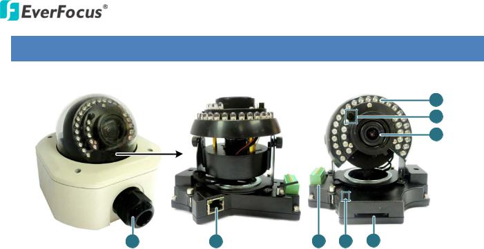
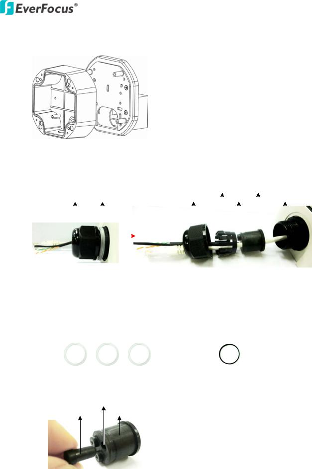
2. Overview
Camera Module
8
7 |
6 |
1 |
2 |
3 |
4 |
5 |
No. |
Item Name |
|
Descriptions |
1 |
Cable Gland |
|
Equipped with three plugs inserted in the cable conduits for |
|
waterproofing. |
||
|
|
|
|
|
|
|
|
2 |
LAN / PoE |
|
Connects to a 10/100 Ethernet or PoE. |
|
|
|
|
3 |
Terminal Block |
|
A 12-pin terminal block. See 4.3 Terminal Block. |
|
|
|
|
4 |
Reset Button |
|
Resets all configurations to the factory default settings. |
|
|
|
|
5 |
SD / SDHC Slot |
|
For inserting an SD / SDHC card |
|
|
|
|
6 |
Lens |
|
Varifocal lens with P-Iris control. |
|
|
|
|
7 |
Light Sensor |
|
Detects lights. |
|
|
|
|
8 |
IR LEDs |
|
33 IR LEDs for infrared illumination in night vision applications. |
|
|
|
|
2

EHN Plus Series
3.Features
1/3” Panasonic CMOS sensor (for EHN3160 Plus / 3260 Plus) 1/2.8” Sony CMOS sensor (for EHN3340 Plus)
Triple streams (stream 1 / 2 / 3 from H.264 or MJPEG)
Up to 30 fps at 1920 x 1080
Supports 15 fps at 2048 x 1536 (only for EHN3340 Plus)
Built-in P-Iris
Built-in SD / SDHC card slot
Removable IR-cut filter for Day / Night function
3-axis mechanism (pan / tilt / rotate)
One alarm input and output
Two-way audio
TV-out
IP66 rating
Wide Dynamic Range (for EHN3160 Plus / 3260 Plus)
Digital Slow Shutter (DSS)
2D / 3D Dynamic Noise Reduction (DNR)
Motion detection
10x digital zoom
Privacy mask
DC 12V / PoE
3
EHN Plus Series
4.Installation
4.1Packing List
Please check that there is no missing item in the package before installing.
• EHN Plus Series Camera x 1 |
• Desiccant Bag x 2 |
||
• Base Plate Screw x 4 |
• Inner Paper x 1 |
||
• |
Screw Anchor x 4 |
• |
Software CD x 1 |
• |
Hexagon Screwdriver x 1 |
• |
Quick Installation Guide x 1 |
Note: Contact the shipper if any items appear to have been damaged in the shipping process. If any items are missing, notify your EverFocus Electronics Corp. Sales Representative or Customer Service Branch. Please also keep the shipping carton for possible future use.
4.2Optional Accessories
You can use the optional accessories to expand the capabilities and versatility of the camera. Please contact your dealer for more information.
• One Adapter Plate with 4 Screws The Adapter Plate is designed for wiring the cables through the bottom of the camera case. For details on how to wire the cables through the bottom of the camera, please refer to 4.5 Basic Installation.
• L-Shaped Mounting Bracket |
To prevent the camera from being damaged by direct |
|
sunlight, it is strongly recommended to use the L-Shaped |
|
Mounting Bracket to mount the camera to the wall. For |
|
details on mounting the camera to the wall using the |
|
L-Shaped Mounting Bracket, please refer to 4.5 Basic |
|
Installation. |
4

EHN Plus Series
4.3Terminal Block
The I/O terminal block, located on the camera module, can be used to develop applications for alarm input and output, two-way audio, TV-output or a variety of other functions.
Note:
1.You can unplug the terminal block from the camera module for easier wiring.
2.Microphones with external power supplies are required.
|
1 |
2 3 |
4 5 6 |
7 8 9 10 11 12 |
|
|
|
|
|
|
|
|
|
|
|
|
|
||||
|
|
|
|
|
|
|
||||
|
|
|
|
|
|
|
Camera Module |
|||
Pin Assignment |
|
|
|
|
|
|
|
|||
|
|
|
|
|
|
|
|
|
||
No. |
Functions |
|
|
|
|
|
No. |
Functions |
||
1 |
12V DC Input |
|
|
7 |
Line Input C |
|||||
|
|
|
|
|
|
|
|
|||
2 |
Digital GND |
|
|
|
|
8 |
Audio GND |
|||
|
|
|
|
|
|
|||||
3 |
Alarm Output C |
|
|
9 |
Audio Output |
|||||
|
|
|
|
|
|
|||||
4 |
Alarm COM C |
|
|
10 |
Audio GND |
|||||
|
|
|
|
|
|
|||||
5 |
Alarm Input C |
|
|
11 |
CVBS Output |
|||||
|
|
|
|
|
|
|
|
|||
6 |
Digital GND |
|
|
|
|
12 |
Digital GND |
|||
|
|
|
|
|
|
|
|
|
|
|
5
EHN Plus Series
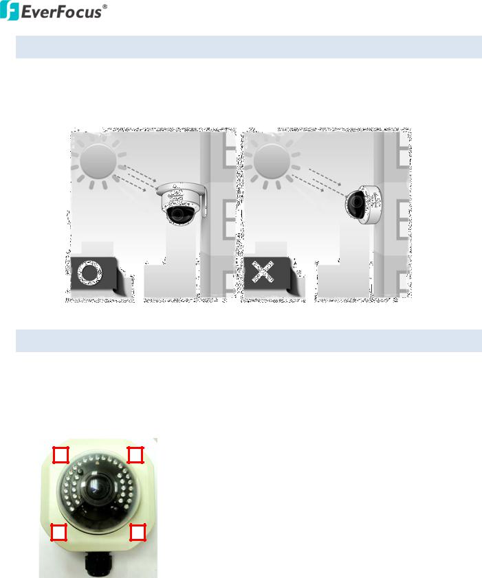
4.4Important Notice for the Installation
If you want to mount the camera on the wall where direct sunlight may occur, it is strongly recommended to mount the camera using the L-Shaped Mounting Bracket to prevent the camera from being damaged by direct sunlight.
4.5Basic Installation
Follow the steps below to install the EHN Plus IP camera to the wall.
To mount the camera to the wall and connect the cables to the related devices:
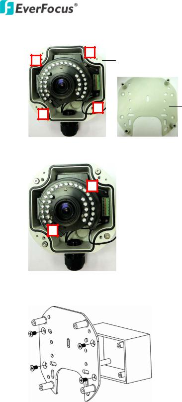
1.Unscrew the four screws and remove the cover from the camera.
6
EHN Plus Series
2.Unscrew the four screws and remove the Base Plate from the Camera Case.
Camera Case
Base Plate
3.Unscrew the two screws and take out the camera module.
4.Screw the Base Plate to the wall / Wiring Box using the supplied four screws.
Wiring Box
Base Plate
7
EHN Plus Series
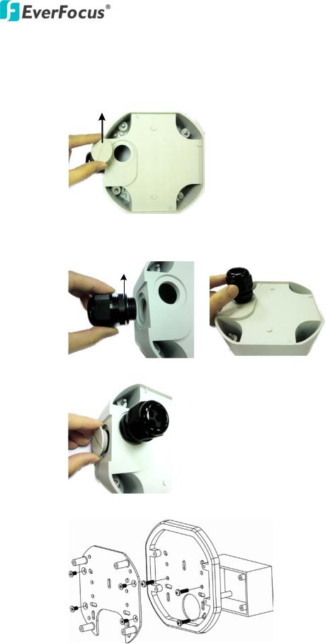
If you want to wire the cables through the bottom of the Camera Case, follow the steps below:
a.Remove the Circle Plate on the bottom of the Camera Case. You can simply loosen the Circle Plate using a coin.
Circle Plate
Camera Case
b.Loosen and remove the Cable Gland from the Camera Case. Screw the Cable Gland to the
hole on the bottom of the Camera Case.
Cable Gland
Camera Case
c.Screw the Circle Plate to the side hole on the camera Case.
d.Screw an Adapter Plate between the Base Plate and Wiring Box.
Wiring Box
Adapter Plate
Base Plate
8
EHN Plus Series
5.Screw the Camera Case back to the Base Plate.
Base Plate
Camera Case
6.Insert the network / PoE cable or the additional cables through the Cable Gland. Up to three cables can be inserted. Note that except the network / PoE cable, additional wires have to be bundled into a cable with diameter ranging from 5.3mm to 6.4mm (see Step d below).
|
|
|
|
|
|
|
Stopper Claw |
Stopper |
|||||
Screw Cap |
Adjustment Ring(s) |
Screw Cap |
|
Plug |
|
Screw Body |
|||||||
|
|
||||||||||||
|
|
|
|
|
|
|
|
|
|
|
|
|
|
|
|
|
|
|
|
|
|
|
|
|
|
|
|
|
|
|
|
|
|
|
|
|
|
|
|
|
|
|
|
|
|
|
|
|
|
|
|
|
|
|
|
Cable Gland |
Cable Gland |
a.Remove the black Adjustment Ring if you are using a Cat 5 network cable. Note that the four Adjustment Rings, including one black and three transparent rings, are attached on the Cable Gland. If you are using a Cat 6 network cable, you can ignore this step. For details on the Adjustment Rings, please refer to 10.1 Adjustment Rings.
• Transparent x 3 (1 mm thickness) |
• Black x 1 (0.5 mm thickness) |
b.Remove the Plug(s) from the Stopper (depends on the number of cables inserted). One Cable Conduit can only be inserted with one cable.
Cable Conduit
Plug Stopper
9

EHN Plus Series
c.Insert the network / PoE cable through the Cable Conduit, if your network / PoE cable already has a RJ-45 connector, then you can use the Slitted Cable Conduit.
Slitted Cable Conduit
d.Optionally insert the additional wires, such as power (if you want to power the camera through a 12V DC power source), alarm and audio cables, through the other Cable Conduit. Note that one Cable Conduit can only be inserted with one cable. The Cable Conduit has been tested to support cable diameter between 5.3mm and 6.4mm. Please refer to the image below to bundle the lose wires before inserting to the Cable Conduit.
e.Tighten the Screw Cap all the way to the Adjustment Ring(s).
f.Due to the variable cable diameters, for better waterproofing, it is strongly recommended that you apply silicon sealants to the inner Screw Cap.
7.Connect the network / PoE cable to the LAN / PoE port on the camera module.
8.If you have inserted additional wires, connect the wires to the terminal block. Please refer to 4.3 Terminal Block for pin assignment.
10

EHN Plus Series
9.Optionally insert an SD / SDHC card to the card slot.


 SD Card Slot
10.Stick the supplied 2 desiccant bags inside the camera case.
Note: It is highly recommended to replace the desiccant bags every time when you open the camera.
11.Place and screw the camera module back to the camera case.
12.Access the camera live view for adjusting camera lens and angles. For details on how to access the camera live view, see 5. Accessing the User Interface.
a. To adjust camera lens, use the Zoom / Focus screws.
Zoom Screw Focus Screw
11
EHN Plus Series
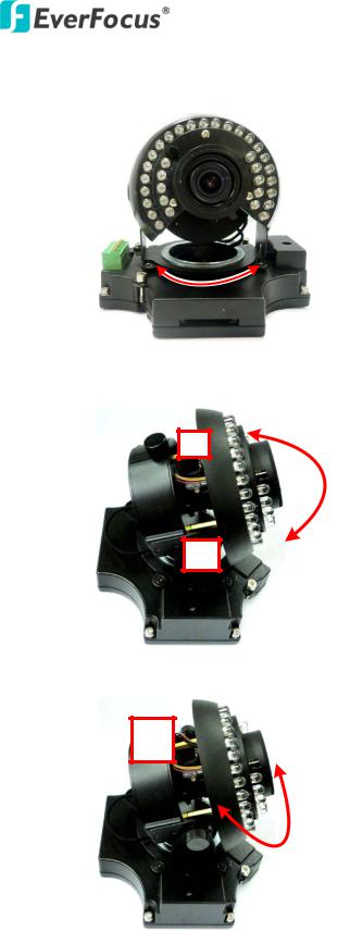
b.To adjust the camera to a desired angle:
Pan Adjustment: Simply turn left / right for the top camera module.
360°
Tilt Adjustment: Using the two tilt screws.
64°
Rotational Adjustment: Using the rotate screw.
180°
13.Screw the cover back to the camera case.
12
EHN Plus Series
5. Accessing the User Interface
This section explains how to access the Web interface of the camera for configuration.
5.1Assigning an IP Address
You have to assign an IP address for your camera to be accessible. To assign an IP address to the camera, use the IP Utility (IPU) software included in the software CD. Please connect the IP camera in the same LAN of your computer.
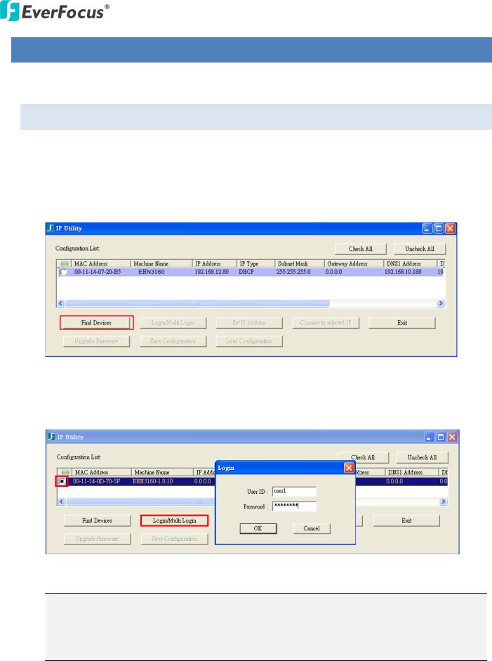
1.Install and then start the IPU program  . The following dialog box appears.
2.Click Find Devices to search the cameras connected in the LAN. The default network values of the cameras will be displayed. By default, the network protocol of the camera is DHCP.
3.To configure the network settings, select a camera and then click Login/Multi Login to log in.
4. Type the user ID and password. Click OK.
Note:
1.The default user ID is user1 and the default password is 11111111.
2.If you select more than one camera that has the same user ID / password, you will be able to log in several cameras at once.
13
EHN Plus Series
5.To change the IP address, double-click the IP Address of the camera. Type a new IP address and then click Set IP Address to save the settings.
You can also change the other settings by double-clicking the values. After configuring the values, click Save Configuration.
Note: Most networks uses DHCP to assign IP addresses, if you are unsure of your network settings, please consult your network administrators for configuration details.
6.To access the camera, highlight the camera and click Connect to Selected IP. The Internet Explorer window pops up.
7.Type the user ID and password to log in. The Live View window of the camera appears.
Note: You might be required to download ActiveX, which is required to view the camera feed. If asked, click "Yes". For more details on setting up the Microsoft Internet Explorer, please refer to 5.2 Settings for Microsoft Internet Explorer.
14
EHN Plus Series
5.2Settings for Microsoft Internet Explorer
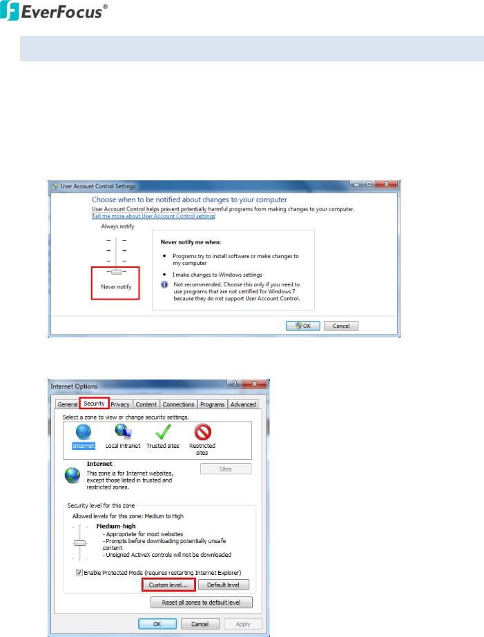
To enable Remove Live View, Firmware Upgrade and ActiveX Prompt on Internet Explorer, some settings have to be complete. Please follow the steps below:
1.On the computer, click Start > Control Panel > System and Security > Action Center (click Change User Account Control Settings), the User Account Control Settings window appears. Adjust the slide bar to Never Notify and then click OK. Restart your computer if requested.
2.Open the Internet Explore, click Tools > Internet Options > Security Tab > Custom Level, the
Security Settings windows appears.
15

EHN Plus Series
3.In the Download unsigned ActiveX controls field, select Prompt. In the Include local directory path when uploading files to a server field, select Enable. Click OK.
4.In the Internet Options window, click the Advanced tab and then disable Enable memory protection to help mitigate online attacks. Click OK.
16
EHN Plus Series
5.3Connecting the Camera to the Network
There are three methods to connect the IP camera to the network: Router or LAN Connection, Direct High-Speed Connection and One-to-One Connection.
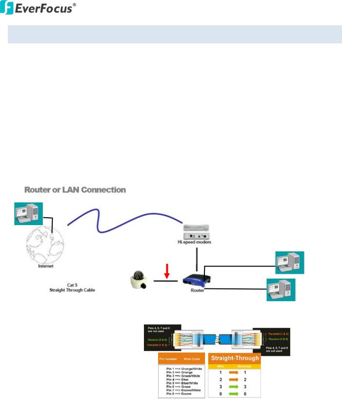
Router or LAN connection
This is the most common connection in which the IP camera is connected to a router and allows multiple users on and off site to see the IP camera on a LAN/WAN (Internet). The camera must be assigned an IP address that is compatible with its LAN. By setting up port forwarding on the router, you can remotely access the cameras from outside of the LAN via the Internet. To remotely access the Web interface of the IP camera, please refer to 7.3.2 DDNS. To set up port forwarding, please consult the manual of the router.
Straight-through LAN patch cable
Right: Pinout of a straight-through cable.
17
EHN Plus Series
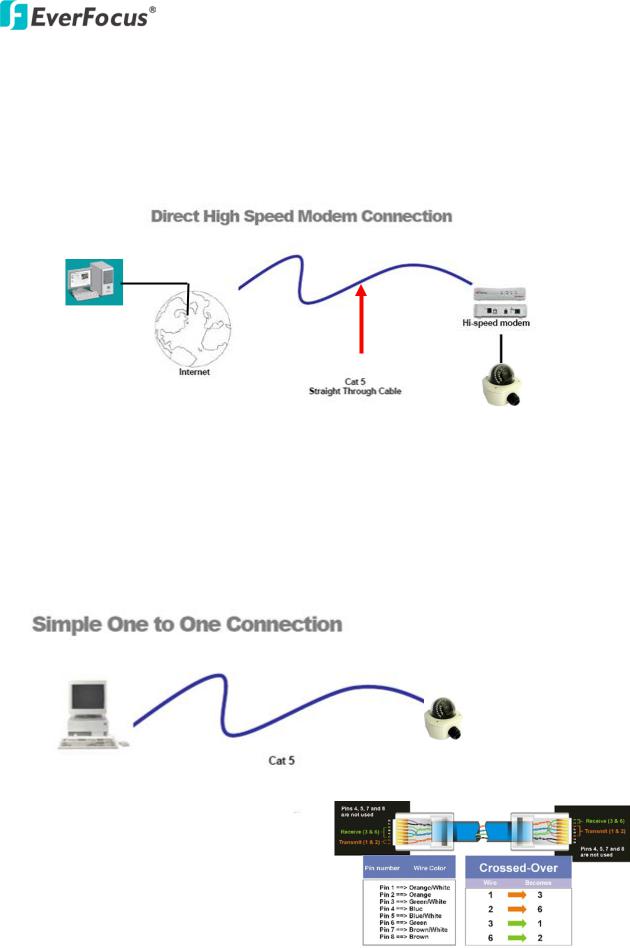
Direct High-Speed Connection
In a Direct High-Speed Connection, the camera connects directly to a modem without the need for a router. You need to set the static or dynamic WAN IP address assigned by your ISP (Internet Service Provider) in the camera’s configuration web pages. To access the camera, just type “http://xxx”, where xxx is the IP address given by your ISP. If you have a dynamic IP address, this connection may require that you use DDNS for a reliable connection. Please refer to 7.3.2 DDNS.
One-to-One Connection (Directly from PC to IP Camera)
You can connect directly without using a switch, router or modem. However, only the PC connected to the camera will be able to view the IP camera. You will also have to manually assign a compatible IP address to both the computer and the IP camera. Unless the PC has another network connection, the IP camera will be the only network device visible to the PC. See the diagram below:
Right: Pinout of a crossed-over cable.
18
Loading...