


 Loading...
ECOR960 4F2 / 8F2 / 16F2 DVR
4 / 8 / 16 CH, H.264, 960H
User’s Manual
Copyright © EverFocus Electronics Corp,
Release Date: February, 2014
Notice: This content is subject to be changed without notice.

E V E RF O CU S E LE CT RO N I C S CO RP O RAT I ON
ECOR960 4F2 / 8F2 / 16F2
User’s Manual
2014 EverFocus Electronics Corp
www.everfocus.com
All rights reserved. No part of the contents of this manual may be reproduced or transmitted in any form or by any means without written permission of the Everfocus Electronics Corporation.
Release Date: February, 2014
QuickTime is a registered trademark of the Apple Computer, Inc. Windows is a registered trademark of the Microsoft Corporation.
Linksys is a registered trademark of the Linksys Corporation. D-Link is a registered trademark of the D-Link Corporation.
DynDNS is a registered trademark of the DynDNS.org Corporation.
Other product and company names mentioned herein may be the trademarks of their respective owners.

Safety Precautions
Refer all work related to the installation of this product to qualified service personnel or system installers.
Do not block the ventilation openings or slots on the cover.
Do not drop metallic parts through slots. This could permanently damage the appliance. Turn the power off immediately and contact qualified service personnel for service.
Do not attempt to disassemble the appliance. To prevent electric shock, do not remove screws or covers. There are no user-serviceable parts inside. Contact qualified service personnel for maintenance. Handle the appliance with care. Do not strike or shake, as this may damage the appliance.
Do not expose the appliance to water or moisture, nor try to operate it in wet areas. Do take immediate action if the appliance becomes wet. Turn the power off and refer servicing to qualified service personnel. Moisture may damage the appliance and also may cause electric shock.
Do not use strong or abrasive detergents when cleaning the appliance body. Use a dry cloth to clean the appliance when it is dirty. When the dirt is hard to remove, use a mild detergent and wipe gently.
Do not overload outlets and extension cords as this may result in a risk of fire or electric shock.
Do not operate the appliance beyond its specified temperature, humidity or power source ratings. Do not use the appliance in an extreme environment where high temperature or high humidity exists. Use the DVR at temperatures within 0°C~40°C / 32°F~104°F (Storage). The input power source is 12 VDC.
Read Instructions
All the safety and operating instructions should be read before the unit is operated.
Retain Instructions
The safety and operating instructions should be retained for future reference.
Heed Warnings
All warnings on the unit and in the operating instructions should be adhered to.
ii

Follow Instructions
All operating and use instructions should be followed.
Cleaning
Unplug the unit from the outlet before cleaning. Do not use liquid cleaners, abrasive or aerosol cleaners. Use a damp cloth for cleaning
Attachments
Do not use attachments not recommended by the product manufacturer as they may cause hazards.
Water and Moisture
Do not use this unit near water-for example, near a bath tub, wash bowl, kitchen sink, or laundry tub, in a wet basement, near a swimming pool, in an unprotected outdoor installation, or any area which is classified as a wet location.
Servicing
Do not attempt to service this unit by yourself as opening or removing covers may expose you to dangerous voltage or other hazards. Refer all servicing to qualified service personnel.
Power Cord Protection
Power supply cords should be routed so that they are not likely to be walked on or pinched by items placed upon or against them, playing particular attention to cords and plugs, convenience receptacles, and the point where they exit from the appliance.
Object and Liquid Entry
Never push objects of any kind into this unit through openings as they may touch dangerous voltage points or short-out parts that could result in a fire or electric shock. Never spill liquid of any kind on the unit.
Battery
Risk of explosion if battery is replaced by an incorrect type. Dispose of used batteries according to the instructions.
a.Use only two AAA dry cell batteries.
b.Do not dispose of the batteries in a fire as it may explode.
ATTENTION! This is a class A product which may cause radio interference in a domestic environment; in this case, the user may be urged to take adequate measures.
iii

|
|
|
Federal Communication Commission Interference Statement |
|
|
|
|
This equipment has been tested and found to comply with the limits for a Class B digital |
|
|
|
|
device, pursuant to Part 15 of the FCC Rules. These limits are designed to provide |
|
|
|
|
reasonable protection against harmful interference in a residential installation. This |
|
|
|
|
equipment generates, uses and can radiate radio frequency energy and, if not installed |
|
|
|
|
and used in accordance with the instructions, may cause harmful interference to radio |
|
|
|
|
communications. However, there is no guarantee that interference will not occur in a |
|
|
|
|
particular installation. If this equipment does cause harmful interference to radio or |
|
|
|
|
television reception, which can be determined by turning the equipment off and on, the |
|
|
|
|
user is encouraged to try to correct the interference by one of the following measures: |
|
|
|
|
•Reorientor relocatethereceiving antenna. |
|
|
|
|
•Increasetheseparation between the equipment and receiver. |
|
|
|
|
•Connect theequipment into anoutleton a circuit different from thatto whichthe |
|
|
|
|
receiver is connected. |
|
|
|
|
•Consult the dealeror anexperiencedradio/TVtechnician for help. |
|
|
|
|
FCC Caution: Any changes or modifications not expressly approved by the party |
|
|
|
|
responsible for compliance could void the users’ authority to operate this equipment. |
|
|
|
|
|
|
|
|
|
|
|
|
|
|
This Product is RoHS compliant. |
|
|
|
|
|
|
|
|
|
|
|
|
|
|
Your EverFocus product is designed and manufactured with high quality materials and |
|
|
|
components which can be recycled and reused. This symbol means that electrical and |
|
|
WEEE |
|
|
|
|
|
|
|
electronic equipment, at their end-of-life, should be disposed of separately from your |
|
|
|
|
||
|
|
|
household waste. Please, dispose of this equipment at your local community waste |
|
|
|
|
collection/recycling centre. In the European Union there are separate collection systems |
|
|
|
|
for used electrical and electronic product. |
|
|
|
|
Please, help us to conserve the environment we live in! |
|
|
|
|
|
|
This product complies with the High-Definition Multimedia Interface (HDMI)
Specification Adopter Agreement.
The information in this manual was current upon publication. The manufacturer reserves the right to revise and improve his products. Therefore, all specifications are subject to change without prior notice. Manufacturer is not responsible for misprints or typographical errors.
Please read this manual carefully before installing and using this unit. Be sure to keep it handy for later reference.
iv

TABLE OF CONTENTS
1. |
Introduction................................................................................................................... |
1 |
||
|
1.1 |
Features......................................................................................................................... |
4 |
|
|
1.2 |
Packing List .................................................................................................................... |
5 |
|
|
1.3 |
Optional Accessories ..................................................................................................... |
5 |
|
|
1.4 |
Front Panel .................................................................................................................... |
6 |
|
|
1.5 |
Rear Panel...................................................................................................................... |
8 |
|
2. |
Installation................................................................................................................... |
|
10 |
|
|
2.1 |
Hard Disk installation .................................................................................................. |
10 |
|
|
|
2.1.1 Hard Disk Compatibility List.............................................................................. |
14 |
|
|
2.2 |
Basic Connection ......................................................................................................... |
15 |
|
|
|
2.2.1 |
Monitor Connection ......................................................................................... |
16 |
|
|
2.2.2 Alarm I / O......................................................................................................... |
17 |
|
|
|
2.2.3 |
RS-485 Port ....................................................................................................... |
18 |
|
2.3 |
Turning On / Off the Power......................................................................................... |
18 |
|
|
2.4 |
Checking the Dynamic IP Address ............................................................................... |
19 |
|
|
2.5 |
Connecting the DVR to the Network........................................................................... |
22 |
|
|
|
2.5.1 Router or LAN Connection................................................................................ |
22 |
|
|
|
2.5.2 |
Direct High-Speed Connection ......................................................................... |
25 |
|
|
2.5.3 |
One-to-One Connection ................................................................................... |
26 |
3. Mouse and Front Panel Button Operation .................................................................... |
30 |
|||
|
3.1 |
USB Mouse Operation................................................................................................. |
30 |
|
|
|
3.1.1 How to Select a Channel / Enable Audio.......................................................... |
30 |
|
|
|
3.1.2 |
OSD Root Menu ................................................................................................ |
30 |
|
|
3.1.3 |
Field Input Options ........................................................................................... |
31 |
|
3.2 |
Front Panel Buttons Operation ................................................................................... |
32 |
|
|
|
3.2.1 |
Front Panel Review........................................................................................... |
32 |
|
|
3.2.2 How to Select a Channel / Enable Audio.......................................................... |
32 |
|
|
|
3.2.3 |
OSD Root Menu ................................................................................................ |
32 |
|
|
3.2.4 |
Field Input Options ........................................................................................... |
33 |
|
3.3 |
General Operation....................................................................................................... |
34 |
|
|
|
3.3.1 |
Login ................................................................................................................. |
34 |
|
|
3.3.2 |
Camera Selection.............................................................................................. |
35 |
|
|
3.3.3 |
Audio Selection................................................................................................. |
36 |
4. |
OSD Root Menu ........................................................................................................... |
37 |
||
4.1 |
PTZ ................................................................................................................................... |
|
39 |
|
v

|
|
4.1.1 Express Control of PTZ...................................................................................... |
41 |
|
|
4.2 |
Layout Switching ......................................................................................................... |
42 |
|
|
4.3 |
Channel Switching ....................................................................................................... |
42 |
|
|
4.4 |
Display ......................................................................................................................... |
43 |
|
|
4.5 |
Sequence ..................................................................................................................... |
43 |
|
|
4.6 |
Zoom |
............................................................................................................................ |
44 |
|
4.7 |
Archiving .......................................................the Recordings or Log Data to the USB |
45 |
|
|
4.8 |
Logout.......................................................................................................................... |
46 |
|
|
|
4.8.1 .......................................................................................... |
Temporarily Logout |
47 |
5. |
Search and .....................................................................................................Playback |
48 |
||
|
5.1 |
Quick .............................................................................................................Playback |
48 |
|
|
5.2 |
Playback ................................................................................................................Bar |
49 |
|
|
5.3 |
Searching .................................................................the Recordings for Playing Back |
51 |
|
|
|
5.3.1 ...................................................................................................... |
Time Search |
51 |
|
|
5.3.2 ..................................................................................................... |
Event Search |
52 |
|
|
5.3.3 ..................................................................................................... |
Smart Search |
53 |
|
|
5.3.4 ............................................................................................... |
Snapshot Search |
55 |
6. |
Configuration............................................................................................................... |
57 |
||
|
6.1 |
Express......................................................................................................................... |
59 |
|
|
6.2 |
Camera ........................................................................................................................ |
61 |
|
|
|
6.2.1 ...................................................................................................... |
Basic Setting |
61 |
|
|
6.2.1.1 ........................................................................................Display Aspect Ratio |
63 |
|
|
|
6.2.2 ................................................................................................... |
Adjust Setting |
64 |
|
6.3 |
Record ......................................................................................................................... |
65 |
|
|
6.4 |
Event............................................................................................................................ |
|
66 |
|
|
6.4.1 ................................................................................................................ |
Alarm |
66 |
|
|
6.4.2 ......................................................................................................... |
Video Loss |
68 |
|
|
6.4.3 .............................................................................................................. |
Motion |
70 |
|
|
6.4.4 ................................................................................................................. |
Other |
73 |
|
6.5 |
Hard D ......................................................................................................................ISK |
79 |
|
|
|
6.5.1 |
Disk 79 |
|
|
|
6.5.2 ...................................................................................................... |
Lock/Format |
80 |
|
6.6 |
Display .............................................................................................................Setting |
81 |
|
|
|
6.6.1 ..................................................................................................... |
Monitor OSD |
81 |
|
|
6.6.2 ............................................................................................................ |
M/T SEQ |
82 |
|
6.7 |
Network .........................................................................................................Settings |
83 |
|
|
|
6.7.1 |
LAN 83 |
|
|
|
6.7.2 ................................................................................................................. |
86 |
|
|
|
6.7.3 ................................................................................................................. |
DDNS |
87 |
|
|
6.7.4 |
FTP 90 |
|
vi

|
|
6.7.5 |
Alarm Server ..................................................................................................... |
91 |
|
|
6.7.6 |
Network Testing ............................................................................................... |
92 |
|
6.8 |
Schedule Setting.......................................................................................................... |
93 |
|
|
|
6.8.1 |
Express Setup.................................................................................................... |
93 |
|
|
6.8.2 |
Holidays ............................................................................................................ |
94 |
|
|
6.8.3 |
Schedule ........................................................................................................... |
95 |
|
6.9 |
System Setting............................................................................................................. |
98 |
|
|
|
6.9.1 |
Date / Time ..................................................................................................... |
98 |
|
|
6.9.2 |
Daylight Saving ................................................................................................. |
99 |
|
|
6.9.3 |
User Group...................................................................................................... |
100 |
|
|
6.9.4 |
User Management.......................................................................................... |
101 |
|
|
6.9.5 |
I/O Control...................................................................................................... |
104 |
|
|
6.9.6 |
EKB200 Setting................................................................................................ |
105 |
|
|
6.9.7 |
Miscellaneous................................................................................................. |
107 |
|
6.10 |
Information ............................................................................................................. |
109 |
|
|
|
6.10.1 |
System ......................................................................................................... |
109 |
|
|
6.10.2 |
Log................................................................................................................ |
110 |
7. Remote Access to the DVR ......................................................................................... |
111 |
|||
|
7.1 |
Accessing the DVR on the Network........................................................................... |
111 |
|
|
7.2 |
Install JAVA Runtime ................................................................................................. |
113 |
|
|
7.3 |
Browser Security Setting ........................................................................................... |
115 |
|
|
|
7.3.1 |
Installing ActiveX Controls.............................................................................. |
115 |
|
|
7.3.2 |
Enabling ActiveX Controls............................................................................... |
116 |
|
7.4 |
Remote Live View...................................................................................................... |
119 |
|
|
7.5 |
Menu Bar................................................................................................................... |
121 |
|
|
7.6 |
Remote Playback ....................................................................................................... |
122 |
|
8. |
Specifications............................................................................................................. |
123 |
||
9. |
Troubleshooting......................................................................................................... |
125 |
||
Appendix A: Network Overview......................................................................................... |
126 |
|||
Appendix B: Linksys & D-Link Port Forwarding ................................................................... |
130 |
|||
Appendix C: Timing of Alarm Modes .................................................................................. |
134 |
|||
Appendix D: Express Setup Recording Value Selection Rules .............................................. |
137 |
|||
Appendix E: IR Remote Control.......................................................................................... |
139 |
|||
vii

Important Notice
The 960H DVR is designed to deliver and record the best analog image quality of 700TVL cameras in WD1 mode (NTSC: 960x480 / 960x240 / 480x240; PAL: 960X576 / 960X288 / 480X288). The DVR also provides the flexibility for users to change the Recording Format from WD1 to D1 mode (NTSC: 704X480 / 704X240 / 352X240; PAL: 704X576 / 704X288 / 352X288) if needed. To select the desired Recording Format, please see 6.6.1 Monitor OSD.
Before switching the WD1 / D1 modes, please be advised of the following notes:
1.Switching between the WD1 and the D1 mode will REBOOT the DVR.
2.Resolution selection options will change as the mode switches, please refer to 6.2.1 Basic Setting.
viii

ECOR960 4F2 / 8F2 / 16F2
Chapter
1
1. Introduction
EverFocus brings you the next generation of analog recording. The new ECOR960 4F2 / 8F2 /16F2 digital video recorder benefits users by digitizing the highest quality, state of the art 960H cameras for live and remote monitoring, surveillance review, and archival. The ECOR960 4F2 / 8F2 / 16F2 also supports (120 / 240 / 480 FPS total) recording over 4 / 8 /16-channels @ WD1 (960x480 / 960x576) resolution, providing the ability to capture objects at enhanced detail levels.
The ECOR960 4F2 / 8F2 / 16F2 DVR also supports convenient video export operations to USB. Its dual stream H.264 encoder provides users smooth remote viewing experience in low bandwidth networks while simultaneously preserving a high quality recording in the DVR hard disk. The ECOR960 4F2 / 8F2 / 16F2 can provide clear 1080p Full HD Video output to both HDMI and VGA monitors with an intuitive onscreen user interface for efficient operation. User can also easily operate the machine using a USB mouse or via the front panel buttons.
When paired with our powerful EverFocus PowerVideo Plus CMS, the ECOR960 4F2 / 8F2 / 16F2 can be used in complex multi-site installations, with centralized management. The ECOR960 4F2 / 8F2 / 16F2 is also fully supported by the EverFocus MobileFocus remote viewer on iOS and Android devices, which help extend video surveillance from fix location to mobile environments.
960H is the highest resolution for analog CCTV, increasing resolution by 30% compared to D1. With the better resolution benefited by 960H, the definition of video image will certainly be higher. Moreover, the 960H CCD sensor performs greater image clarity in low-light environment than IP and HD-SDI CMOS sensors. A 960H DVR, like our new ECOR960 4F2 / 8F2 / 16F2 DVR, can support cameras with resolution up to700TVL and you can use the existing coaxial infrastructure without the need of re-cabling.
1
ECOR960 4F2 / 8F2 / 16F2
ECOR960 4F2 / 8F2 System Diagram
Mouse or USB
Memory Stick *Internal 3.5" HDDs (Optional) IR Remote Control a
*Analog Camera |
Call Monitor |
Main Monitor |
Alarm In |
Audio |
|
|||||
(BNC) |
|
(VGA) |
/ Out |
Cable |
*Line Level |
|||||
|
|
|
||||||||
|
|
|
|
|
|
|
|
|
|
Audio In 3~8 |
|
|
|
|
|
|
|
|
|
|
|
|
|
|
|
|
|
|
|
|
|
|
|
|
|
|
|
|
|
|
|
|
|
|
|
|
|
|
|
|
|
|
|
|
|
|
|
|
|
|
|
|
|
|
|
|
|
Power Supply |
|
Network |
|
Line Level |
|
RS-485 Device |
Audio Out |
|
|
Line Level |
|
|
Audio In 1~2 |
Main Monitor |
Mouse or USB Memory Stick |
|
(HDMI) |
|
|
|
|
|
Web Remote Client |
PowerVideo Plus (CMS) |
Figure 1-1
* This diagram uses ECOR960 8F2 as an example. The ECOR960 4F2 only has 4 Video Inputs, 4 Audio Inputs, and supports only 1 hard disk drive.
2

ECOR960 4F2 / 8F2 / 16F2
ECOR960 16F2 System Diagram
Mouse or USB |
*Internal 3.5" HDDs (Optional) |
|
Memory Stick |
IR Remote Control |
*Analog Camera |
|
Line Level |
Alarm In |
Power |
|
Call Monitor |
Audio In Audio Cable |
/ Out |
Supply |
||
|
(BNC)
RS-485 Device
Network
Line Level
Audio Out Main Monitor  Mouse / USB Memory Stick
(HDMI)
Main Monitor
(VGA)
Web Remote Client PowerVideo Plus (CMS)
Figure 1-2
3

ECOR960 4F2 / 8F2 / 16F2
1.1 Features
•4 / 8 / 16 CH WD1 real-time recording and playback
•WD1 capability provides higher resolution (960x576 / 960x480) compared to D1
•H.264 compression format for enhancing recording capacity and improving network image transmission speed
•Two Main Monitors: Both HDMI and VGA ports can be used as the Main monitor outputs at the same time
•Call Monitor: Sequenced view through composite BNC output with multiplex and sequencing
•Free Everfocus DDNS Service – static IP address is not required for reliable remote access
•Supports live monitoring and playback of video from mobile devices via Mobile applications (MobileFocus / MobileFocus Plus)
•Multiple Control Inputs: Mouse / front panel / remote controller
•Multiple intelligent video query functionality, including snapshot and smart search
•Powerful archive functionality from both remote and DVR sites
•Simplified access to common features such as setup, archival, playback and search functions through OSD root menu
•Remote configuration support from built-in web interface
•On-screen PTZ control via mouse, front panel, remote controller or EKB500 keyboard
•Dual USB 2.0 ports for video archive and mouse control
•Integration with EverFocus’ CMS (PowerVideo Plus)
•Multi-language support
4

ECOR960 4F2 / 8F2 / 16F2
1.2 Packing List
• ECOR960 4F2 / 8F2 / 16F2 DVR x1 |
• Mouse x 1 |
• Adaptor x 1 |
• Power Cord x 1 |
• HDD Mounting Screw x 8 (16F2/8F2) |
• User Manual x 1 |
x 4 (4F2) |
|
|
|
• CD x 1 |
• Audio Cable x 1 |
• BNC to RCA Connector x1 (4F2/8F2) |
• Remote Controller x 1 |
Note:
1.Equipment configurations and supplied accessories vary by country. Please consult your local EverFocus office or agents for more information. Please also keep the shipping carton for possible future use.
2.Contact the shipper if any items appear to have been damaged in the shipping process.
3.Two SATA cables will be supplied for DVRs without HDDs installed. If the order contains HDD installation, the SATA cable will not be supplied.
4.Risk of explosion if battery is replaced by an incorrect type. Dispose of used batteries according to the instructions.
a.Use only two AAA dry cell batteries.
b.Do not dispose of the batteries in a fire as it may explode.
1.3 Optional Accessories
•EKB200 (USB controller keyboard: connect to the PC or DVR to control the PTZ cameras connected to the DVR). Please refer to 6.9.6 EKB200 Setting and the User Manual of the EKB200 Keyboard.
•EKB500 (RS-485 keyboard: connect to the RS-485 port to control the PTZ cameras connected to the DVR). Please refer to User Manual of the EKB500 Keyboard.
5
ECOR960 4F2 / 8F2 / 16F2
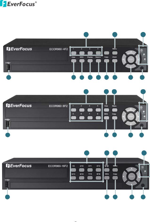
1.4 Front Panel
ECOR960 4F2
12 |
11 |
10 |
1 |
2 |
3 |
4 |
5 |
6 |
7 |
8 |
9 |
ECOR960 8F2
12 |
2 |
11 |
10 |
1 |
3 |
6 |
8 |
9 |
ECOR960 16F2
12 |
13 |
11 |
10 |
1 |
3 |
6 |
8 |
9 |
Figure 1-3
6

|
|
|
ECOR960 4F2 / 8F2 / 16F2 |
|
|
|
|
|
|
No. |
Name |
|
Description |
|
1 |
USB2.0 Port |
|
The USB2.0 ports for connecting to a mouse or external storage |
|
|
device. |
|
||
|
|
|
|
|
2 |
View |
|
Press the type of layout you want for displaying your channel feeds. |
|
|
|
|
|
|
3 |
SEQ (Sequence) |
|
Press to enter the automatic sequence mode. This will show each |
|
|
channel feed in sequence. |
|
||
|
|
|
|
|
|
|
|
|
|
4 |
Display |
|
Press to cycle between the info display types (channel and status bar |
|
|
info). |
|
||
|
|
|
|
|
5 |
Search |
|
Press to enter the Search Setup menu. |
|
|
|
|
|
|
6 |
Copy |
|
Press to enter the Copy Menu. |
|
|
|
|
|
|
7 |
Zoom |
|
Press repeatedly to toggle between 2x and 4x zoom. Press the Menu |
|
|
button to switch zoom off. |
|
||
|
|
|
|
|
8 |
Arrow Keys |
|
Use these arrow keys to change the Menu settings. |
|
|
|
|
|
|
9 |
IR Receiver |
|
Receiver for IR Remote Control. |
|
|
|
|
|
|
|
|
|
Power LED: Indicates the power is on. |
|
10 |
Status LED |
|
Record LED: Indicates the DVR is recording. |
|
|
Alarm LED: Indicates the alarm input is triggered. (Note: ECOR960 |
|
||
|
|
|
|
|
|
|
|
16F2 doesn’t have the Alarm LED). |
|
11 |
Menu |
|
Press to enter/exit the Main Setup Menu. |
|
|
|
|
|
|
12 |
Channel 1~4 / |
|
Press to display the channel in full screen. |
|
1~8 / 9~16 |
|
|
||
|
|
|
|
|
13 |
Channel Switch |
|
Press this button to switch the above channel button numbers |
|
|
between 1~8 and channel 9~16. |
|
||
|
|
|
|
|
7

ECOR960 4F2 / 8F2 / 16F2
1.5 Rear Panel
ECOR960 4F2
ECOR960 8F2
1 |
2 |
3 |
|
7 |
|
1 |
2 |
3 |
4 |
5 |
6 |
8 |
9 |
10 |
11 12 |
13 |
4 |
|
5 |
|
6 |
7 |
8 |
9 |
10 |
11 12 |
13 |
ECOR960 16F2
1 |
2 |
3 |
13 |
5 |
6 |
7 |
8 |
4 |
9 |
10 |
11 |
12 |
Figure 1-4
8

|
|
|
ECOR960 4F2 / 8F2 / 16F2 |
|
|
|
|
No. |
Name |
|
Description |
1 |
Video Input |
|
Connect up to 4 / 8 cameras using the coaxial cables. |
|
|
|
|
2 |
Call Monitor Port (BNC) |
|
Connects to the Call monitor using a BNC cable. |
|
|
|
|
|
|
|
Connects to the audio input devices such as microphones. |
3 |
Audio Input 1~2 (RCA) |
|
Note that the microphone with a (built-in) amplifier and |
|
|
|
external power supply is required. |
|
|
|
|
4 |
Main Monitor Port (VGA) |
|
Connects to the Main monitor using a VGA cable. |
|
|
|
|
5 |
Alarm Input / Output |
|
Connects to 4 alarm inputs, and to 1 alarm output device. |
|
|
|
|
6 |
Power |
|
Press to turn on or off the power. |
|
|
|
|
|
Audio Output BNC |
|
If it is a BNC connector, please connects to the audio output |
|
|
devices, such as speakers, using the supplied BNC to RCA |
|
7 |
(4F2/8F2) |
|
|
|
Connector. Note that the speaker with a (built-in) amplifier |
||
|
Audio Output RCA (16F2) |
|
|
|
|
and external power is required. |
|
|
|
|
|
|
|
|
|
8 |
Main Monitor Port (HDMI) |
|
Connects to the Main monitor using a HDMI cable. |
|
|
|
|
9 |
LAN |
|
Connects to the Network. |
|
|
|
|
|
|
|
Connects to USB storage device to copy / archive video or for |
10 |
USB Interface |
|
firmware upgrades. Use the other port for connecting the |
|
|
|
mouse. |
|
|
|
|
11 |
RS-485 Port |
|
Connects to the RS-485 device, such as EverFocus’ EKB-500 |
|
keyboard. |
||
|
|
|
|
|
|
|
|
12 |
Power Port |
|
Connects to the DC 12V power using the supplied Power |
|
Cord. |
||
|
|
|
|
|
|
|
|
|
Audio Input 3~4 (4F2) |
|
Connects to the audio input devices using the supplied Audio |
13 |
Audio Input 3~8 (8F2) |
|
|
|
Cable. |
||
|
Audio Input 3~16 (16F2) |
|
|
|
|
|
|
|
|
|
|
9

ECOR960 4F2 / 8F2 / 16F2
Chapter
2
2.Installation
2.1Hard Disk installation
ECOR960 4F2/8F2:
You can optionally install two 3.5” HDDs inside the ECOR960 8F2 DVR or one 3.5” HDD inside the ECOR960 4F2 DVR for recording videos. (The HDD installation instruction uses ECOR960 8F2 DVR as an example).
1.Make sure the DVR is power-off.
2.Unscrew the three housing screws on the back panel of the DVR.
Figure 2-1
3.Push the housing to the back and open it.
Figure 2-2
10
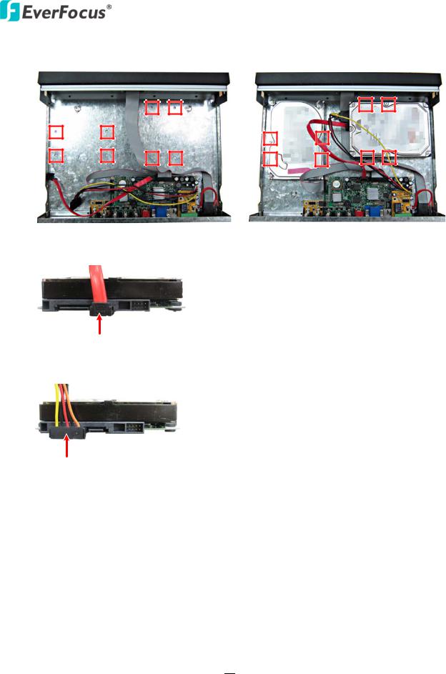
ECOR960 4F2 / 8F2 / 16F2
4.Screw the HDD to the bottom of the DVR using supplied screws. (8CH DVR)
Figure 2-3
5.Connect the internal SATA cable to the SATA port of the HDD.
Figure 2-4
6.Connect the internal power cable to the HDD.
Figure 2-5
7.Screw back the hosing to the DVR.
8.Format the HDD after the installation is completed.
11
ECOR960 4F2 / 8F2 / 16F2
ECOR960 16F2:
You can optionally install two 3.5” HDDs inside the ECOR960 16F2 DVR.
1.Follow the above same step 1~3 to open the housing of the ECOR960 16F2.
Figure 2-6
2.The HDDs have to be mounted upside down with the connectors facing inwards, so please slide the HDD under the HDD Bracket.
HDD Bracket
Figure 2-7
3.Screw the HDD upside down with the four supplied screws.
Figure 2-8
12

ECOR960 4F2 / 8F2 / 16F2
4.Follow the steps above to install the other HDD.
Figure 2-9
5.Connect the internal SATA cable to the SATA port of the HDD and the internal power cable to the HDD as the Figure 2-4 and Figure 2-5.
Figure 2-10
6.Screw back the hosing to the DVR.
7.Format the HDD after the installation is completed.
13

ECOR960 4F2 / 8F2 / 16F2
2.1.1 Hard Disk Compatibility List
Please use the hard disk models recommended in the list below to ensure your hard disks will be compatible.
SATA Hard Disk |
Model |
Capacity |
|
Constellation ES.3 SATA3 ST4000NM0033 |
4TB |
|
Constellation CS SED SATA3 ST3000NC000 |
3TB |
Seagate |
CE-Video SATA3 / ST3500312CS |
500GB |
|
|
|
CE-Video SATA3 / ST1000VM002 |
1TB |
|
|
CE-Video SATA3 / ST2000VM003 |
2TB |
|
CE-Video SATA3 / ST3000VM002 |
3TB |
|
CE-Video SATA3 / ST4000VM000 |
4TB |
|
WD10EURX SATA3 |
1TB |
|
WD20EURS SATA2 |
2TB |
Western Digital |
WD30EURS SATA2 |
3TB |
WD10EVVS SATA |
1TB |
|
|
WD20EFRX |
2TB |
|
WD30EFRX |
3TB |
|
WD4001FAEX |
4TB |
Note: If using two or more hard disks, please choose the hard disks with the same capacity.
14
ECOR960 4F2 / 8F2 / 16F2
2.2 Basic Connection
The instructions below the figure describe the basic connection for the ECOR960 4F2 / 8F2 /16F2 DVR. (This figure uses ECOR960 16F2 DVR as an example).
Analog Camera |
Line Level |
|
|
Power Supply |
||||||
Audio In |
Audio Cable |
|||||||||
|
|
|||||||||
1 |
|
|
|
|
|
2 |
|
3 |
|
|
|
|
|
|
|
|
|||||
|
|
|
|
|
|
|
|
|
|
|
|
|
|
|
|
|
|
|
|
|
|
|
|
|
|
|
|
|
|
|
|
|
|
|
|
|
|
|
|
|
|
|
|
4 |
5 |
6 |
7 |
RS-485 Device
Network
Line Level
Audio Out Main Monitor  Mouse / USB Memory Stick
(HDMI)
Main Monitor
(VGA)
Web Remote Client PowerVideo Plus (CMS)
Figure 2-11
1.Connect the cameras to the DVR using the coaxial cables. 700TVL cameras are recommended.
2.Connect the line level audio input devices to the Audio-in 1 and 2 RCA sockets of the DVR. Connect the line level audio input devices to the Audio-in 3~16 VGA port using the supplied Audio Cable. Note that the audio input devices, such as microphones, are required to have a (built-in) amplifier and external power supply. Please refer to 1.5 Rear Panel.
3.Using the supplied Power Cord, connect one end to the DC 12V port on the DVR and the other end to the DC 12V power outlet.
Note: Please ensure to connect the internal power cables to the internal HDDs before powering on the DVR.
4.To listen to audio of video source, connect speakers to the Audio-out BNC port using the BNC to RCA connector. Note that speakers with a (built-in) amplifier and external power are required.
5.To view videos and control OSD settings, connect a monitor to the HDMI or VGA port using the HDMI or VGA cable supplied by the monitor manufacturer.
6.To manage the DVR over network, use a standard RJ-45 cable to connect the DVR to the network.
7.Optionally connect a mouse to the DVR to control the system. You can also control the system using the supplied IR Remote Control or the control keys on the front panel.
15
ECOR960 4F2 / 8F2 / 16F2
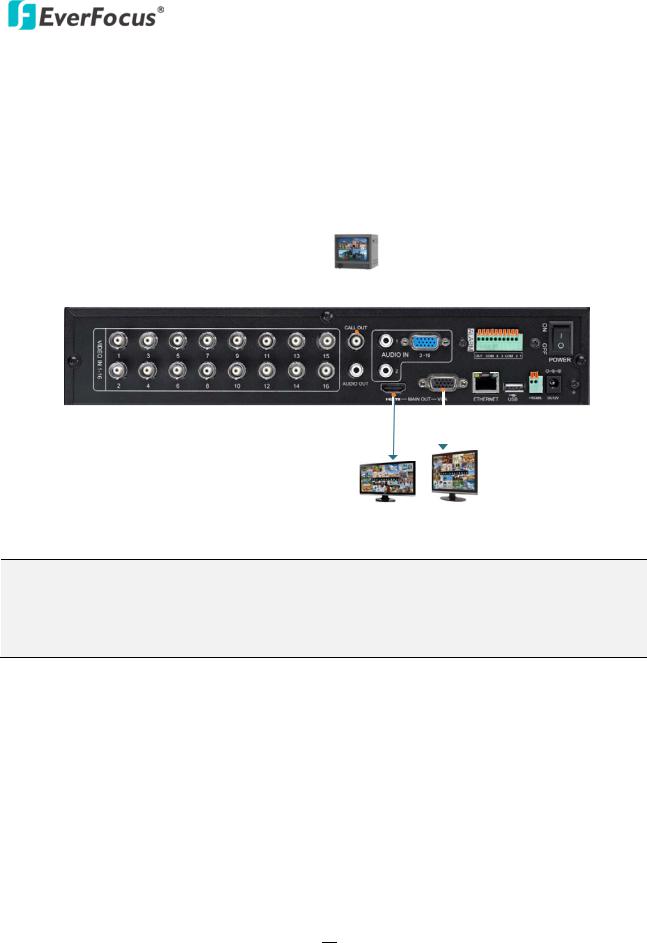
2.2.1Monitor Connection
Connect the monitor to the HDMI, VGA or BNC port on the rear panel of the DVR. The ECOR960 4F2 / 8F2 / 16F2 DVR provides 2 main monitor outputs with identical functionality - VGA and HDMI.
Both outputs can be used simultaneously and deliver full HD output resolution (1920x1080, progressive, 60 Hz. vert., 68 KHz hor.).
Make sure that the connected monitor's specifications comply with these resolution requirements (This figure uses ECOR960 16F2 DVR as an example).
Call Monitor
BNC Cable
HDMI Cable |
VGA Cable |
|
|
Main Monitor Main Monitor
Figure 2-12
Note:
1.The connected monitors’ specifications must comply with the resolution requirements.
2.Do not exceed the max. HDMI cable length of 15 meters. The standard HDMI cables can support cable length up to 3 meters. For longer distances, such as 15 meters, it is highly recommended to use high quality HDMI cables.
16

ECOR960 4F2 / 8F2 / 16F2
2.2.2Alarm I / O
The DVR provides 4 alarm inputs and 1 alarm outputs. Please refer to the table below for PIN assignment.
Alarm Out Alarm In
COM NC G G 4 3 G G 2 1
Figure 2-13
Alarm Input
No.  Description
1-4 ALM_IN1 – ALM_IN4
G GND
Alarm Input Contacts
This DVR provides one alarm input per camera. All inputs are programmable N.O. (Normal Open) or N.C. (Normal Closed). All settings are programmed in the ALARM / Event menu.
ALMIN |
ALMIN |
GND |
GND |
Alarm Input with N.O. contact in idle state |
Alarm Input with N.C. contact in idle state |
Alarm Output Contacts
The relay output provides Normally Closed dry contacts.
17

ECOR960 4F2 / 8F2 / 16F2
2.2.3RS-485 Port
The RS-485 port, located on the rear panel of the DVR, can be used to connect to an RS-485 keyboard, such as EverFocus’ EKB500, for controlling PTZ cameras. For details on the RS-485 configurations on the DVR, please refer to 6.9.5 I/O Control. This figure uses ECOR960 16F2 DVR as an example.
Rear View
RS-485 Port
|
|
|
EKB500 |
|
|
|
|
|
RS-485 |
|
RJ-45 Cable |
PTZ Camera 1~16 |
Connector Box |
||
|
|
||
Figure 2-14
2.3Turning On / Off the Power
Before powering on the DVR, please make sure the internal HDDs have been installed properly. Once you have completed the basic cable connections, you are ready to turn on the DVR.
To turn on the power, connect the supplied Power Cord to the power outlet and turn on the Power Switch. All of the LED indicators on the front panel will light up. The DVR will automatically run an internal process, when the process is complete, the LED indicators will turn off, and the POWER LED will remain light up in green. And then you can start operating the DVR.
To turn off the power, please go to OSD Root Menu > System Setting > Miscellaneous setting page, and click Shutdown (refer to 6.9.7 Miscellaneous). After the message pops up as below, you can now turn the Power Switch to the "Off" position.
Figure 2-15
18

ECOR960 4F2 / 8F2 / 16F2
2.4 Checking the Dynamic IP Address
You can look up the IP address and access the Web interface of the DVR using the IP Utility (IPU) program, which can be downloaded from EverFocus’ Website: http://www.everfocus.com/tools.cfm.
Please connect the DVR in the same LAN of your computer.
1. Install and then start the IPU program . The following dialog box appears.
Figure 2-16
2.IPU will automatically search the IP devices connected in the LAN. The default network values of the IP devices will be displayed. By default, the network protocol of the IP device is DHCP.
3.To configure the network settings, select an IP device and then click Login/Multi Login.
Figure 2-17
19
ECOR960 4F2 / 8F2 / 16F2
4.Type the user ID and password. Click OK.
Note:
1.The default user ID is admin and the default password is 11111111.
2.If you select more than one DVRs that have the same user ID / password, you will be able to log in several DVRs at once.
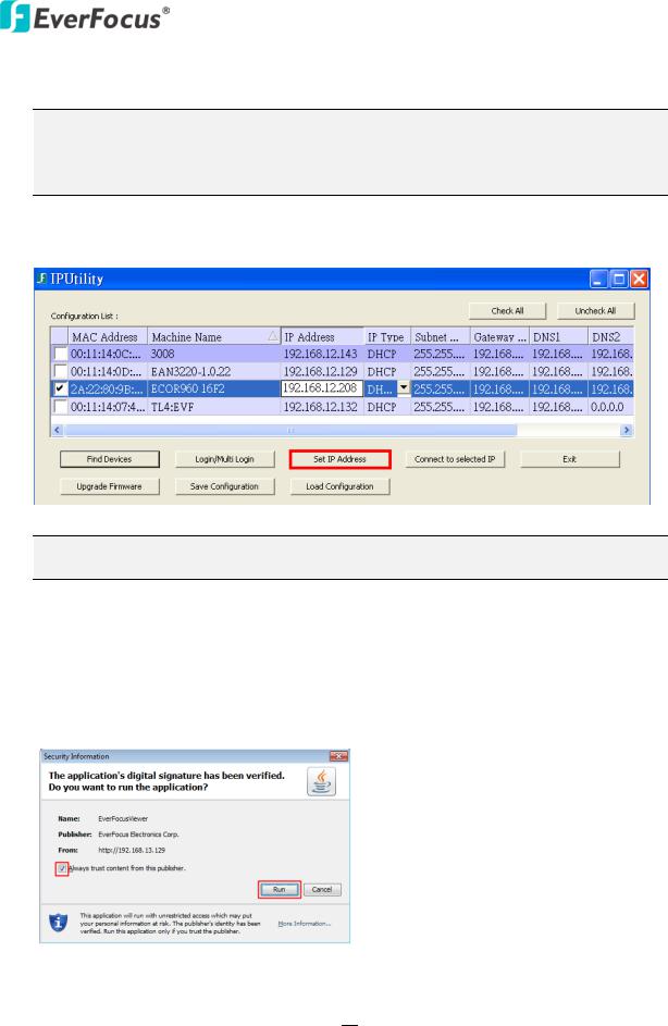
5.To change the IP address, double-click the values in the column and type the numbers or select an option. Click Set IP Address to save the settings.
Figure 2-18
Note: Most networks uses DHCP to assign IP address, if you are unsure of your network settings, please consult your network administrators for configuration details.
6.To access the DVR, highlight the DVR and click Connect to Selected IP. The Internet Explorer window pops up.
7.Type the user ID and password to log in.
8.When first connecting to the DVR’s IP address, the following dialog will appear. Please check the box and click the Run button to run the EverFocus Viewer application.
Figure 2-19
20

ECOR960 4F2 / 8F2 / 16F2
9.You might be required to download ActiveX and JAVA software for viewing the camera feed. If asked, click Yes. For more details, please refer to 7.3.1 Installing ActiveX Controls.
10.You may need to turn User Account Control off if you still can’t see the Remote Live View.
11.On the computer, click Start > Control Panel > System and Security > Action Center (click Change User Account Control Settings), the User Account Control Settings window appears. Adjust the slide bar to Never Notify and then click OK. Restart your computer if requested.
Figure 2-20
21
Loading...