


 Loading...
EverFocus EZN1160-6, EZN1160-3, EZN1160-8, EZN1260-3, EZN1360-8 User Manual
...EZN Series IR Small Bullet IP Camera
True Day/Night, WDR, IP66
User’s Manual
Copyright © EverFocus Electronics Corp,
Release Date: November, 2013

Copyright 2013 EverFocus Electronics Corp.
All rights reserved. No part of the contents of this manual may be reproduced or transmitted in any form or by any means without written permission of the EverFocus Electronics Corporation.
EverFocus
12F, No.79, Sec. 1, Shin-Tai Wu Road, Hsi-Chih, Taipei, Taiwan
TEL: +886 2 2698 2334
FAX: +886 2 2698 2380 www.everfocus.com.tw
November, 2013
About this document
All the safety and operating instructions should be read and followed before the unit is operated. This manual should be retained for future reference. The information in this manual was current when published. The manufacturer reserves the right to revise and improve its products. All specifications are therefore subject to change without notice.
Regulatory Notices
FCC Notice "Declaration of Conformity Information"
This equipment has been tested and found to comply with the limits for a Class
A digital device, pursuant to part 15 of the FCC Rules. These limits are designed to provide reasonable protection against harmful interference in a residential installation. This equipment generates, uses and can radiate radio frequency energy and, if not installed and used in accordance with the instructions, may cause harmful interference to radio communications. However, there is no guarantee that interference will not occur in a particular installation. If this equipment does cause harmful interference to radio or television reception, which can be determined by turning the equipment off and on, the user is encouraged to try to correct the interference by one or more of the following measures:
-Reorient or relocate the receiving antenna.
-Increase the separation between the equipment and receiver.
-Connect the equipment into an outlet on a circuit different from that to which the receiver is connected.
-Consult the dealer or an experienced radio/TV technician for help.
Warning: Changes or modifications made to this equipment, not expressly approved by EverFocus or parties authorized by EverFocus could void the user's authority to operate the equipment.
This device complies with part 15 of the FCC Rules. Operation is subject to the following two conditions:
(1)This device may not cause harmful interference, and
(2)This device must accept any interference received, including interference that may cause undesired operation.
EverFocus Electronics Corp.
12F, No. 79, Sec. 1, Shin-Tai Wu Rd., Hsi-Chi,
Taipei Hsien, Taiwan, R.O.C.
EZN Series cameras comply with CE and FCC.
i
Precautions
1.Do not install the camera near electric or magnetic fields.
Install the camera away from TV/radio transmitters, magnets, electric motors, transformers and audio speakers since the electromagnetic fields generated from these devices may distort the video image or otherwise interfere with camera operation.
2.Never disassemble the camera beyond the recommendations in this manual nor introduce materials other than those recommended herein.
Improper disassembly or introduction of corrosive materials may result in equipment failure or other damage.
3.Try to avoid facing the camera toward the sun.
In some circumstances, direct sunlight may cause permanent damage to the sensor and/or internal circuits, as well as creating unbalanced illumination beyond the capability of the camera to compensate.
4.Keep the power cord away from water and other liquids and never touch the power cord with wet hands.
Touching a wet power cord with your hands or touching the power cord with wet hands may result in electric shock.
5.Never install the camera in areas exposed to oil, gas or solvents.
Oil, gas or solvents may result in equipment failure, electric shock or, in extreme cases, fire.
6.Cleaning
For cameras with interchangeable lenses, do not touch the surface of the sensor directly with the hands. Use lens tissue or a cotton tipped applicator and ethanol to clean the sensor and the camera lens. Use a damp soft cloth to remove any dirt from the camera body. Please do not use complex solvents, corrosive or abrasive agents for cleaning of any part of the camera.
7.Do not operate the camera beyond the specified temperature, humidity or power source ratings.
This camera is suitable for outdoor operation only. Use the camera at temperatures within -20°C~55°C/-4°F~131°F, and humidity between 20% and 85%; this device is not rated as submersible. The input power source is 12 VDC / 24 VAC / PoE. Be sure to connect the proper + / - polarity and voltage, as incorrect polarity or too high a voltage will likely cause the camera to fail, and such damage is not covered by the warranty. The use of properly fused or Class 2 power limited type supplies is highly recommended.
8.Mounting
Use care in selecting a solid mounting surface which will support the weight of the camera plus any wind, snow, ice or other loading, and securely attach the camera to the mounting surface using screws and anchors which will properly support the camera. If necessary (e.g. when mounting to drop ceilings) use a safety wire to provide additional support for the camera.
ii
|
|
|
Contents |
|
1. |
Introduction |
............................................................................................................................... |
1 |
|
2. |
Features ..................................................................................................................................... |
|
2 |
|
3. |
Physical Description ................................................................................................................. |
3 |
||
|
3.1 |
Cables and ............................................................................................................Terminal Block |
3 |
|
|
3.2 |
Dimensions.................................................................................................................................... |
4 |
|
4. |
Installation................................................................................................................................. |
|
5 |
|
|
4.1 |
Packing ....................................................................................................................................List |
5 |
|
|
4.2 |
Basic Installation ........................................................................................................................... |
6 |
|
|
4.3 |
Inserting ...........................................................................................................a Micro SD Card |
10 |
|
5. |
Accessing the .................................................................................................User Interface |
11 |
||
|
5.1 |
Checking ...............................................................................................the Dynamic IP Address |
11 |
|
|
5.2 |
Settings .....................................................................................for Microsoft Internet Explorer |
13 |
|
|
5.3 |
Connecting .....................................................................................the Camera to the Network |
15 |
|
|
5.4 |
Live View .......................................................................................................................Window |
17 |
|
6. |
Playback ................................................................................................................................... |
|
20 |
|
|
6.1 |
Remote .......................................................................................Playback Using Playback Page |
20 |
|
|
6.2 |
Setting Up ...............................................................................................the Playback Function |
22 |
|
|
|
6.2.1 ..................................................................... |
Inserting / Removing the Micro SD Card |
22 |
|
|
6.2.2 ...................................................................................... |
Testing the Playback Function |
23 |
|
6.3 |
Playing Back ...................................................................................................Using ARV Viewer |
25 |
|
7. |
Settings .................................................................................................................................... |
|
26 |
|
|
7.1 |
System Settings ........................................................................................................................... |
27 |
|
|
|
7.1.1 ....................................................................................................................... |
Network |
27 |
|
|
7.1.2 .................................................................................................................. |
Date / Time |
33 |
|
|
7.1.3 ......................................................................................................................... |
Storage |
34 |
|
|
7.1.4 ...................................................................................................... |
Display and Overlay |
36 |
|
|
7.1.5 .................................................................................................... |
System Maintenance |
37 |
|
|
7.1.6 ...................................................................................................... |
System Information |
40 |
|
|
7.1.7 .............................................................................................................................. |
User |
41 |
|
|
7.1.8 ........................................................................................................... |
Black/White List |
43 |
|
7.2 |
Camera ..........................................................................................................................Settings |
44 |
|
|
|
7.2.1 ..................................................................................................................... |
Streaming |
44 |
|
|
7.2.2 ......................................................................................................................... |
Camera |
47 |
iii
|
7.2.3 |
Schedule....................................................................................................................... |
50 |
|
7.2.4 |
Image ........................................................................................................................... |
51 |
|
7.3 Event Settings.............................................................................................................................. |
52 |
|
|
7.3.1 |
Event Wizard ................................................................................................................ |
52 |
|
7.3.2 |
Event ............................................................................................................................ |
53 |
|
7.3.3 |
Notification .................................................................................................................. |
57 |
|
7.4 Link to Smart Phone App ............................................................................................................ |
60 |
|
8. |
Upgrading Firmware Using IP Utility.................................................................................... |
61 |
|
9. |
Specifications .......................................................................................................................... |
63 |
|
10. |
Troubleshooting ...................................................................................................................... |
65 |
|
iv

EZN1160/1260/1360
1.Introduction
The EZN series small bullet, a small form-factor outdoor bullet IP camera, comes with three models, 1.3 MP, 2 MP and 3 MP, providing up to 15 fps at 2048 x 1536 viewing resolution. The series supports quad streams from H.264, MPEG4 or MJPEG video compression formats. Equipped with a weather-resistant (IP66) housing plus eight IR LEDs for enabling the night visibility of up to 20 meters, the cameras meet a wide variety of needs for outdoor surveillance.
The EZN series small bullet IP camera features the Wide Dynamic Range (WDR) function, which can provide clear images even under back light circumstances where intensity of illumination can vary excessively. The DNR (Digital Noise Reduction) function is designed for reducing the noises in the images, allowing the camera to better distinguish between real motion and image noise, and thus results in a possibility to store more video evidence on the connected storage devices.
A built-in micro SDHC card slot and Power over Ethernet (IEEE802.3af) features are also provided. You can power the camera over the network or by connecting the camera to a 12 VDC / 24 VAC power supply. Since the series conforms to ONVIF / PSIA for compatibility with other network video devices, it interoperates with a wide variety of hardware and software systems. You can also use EverFocus Mobile Applications to remotely view the live views of the cameras through your handheld devices; or use EverFocus CMS to remotely manage multiple IP devices connected on the network. The EZN series small bullet IP camera is the ideal solution for your outdoor surveillance needs.
The EMN Series Mini Outdoor/Mobile IP Dome Models
Model Name |
|
Megapixel |
|
WDR |
|
Fixed Lens (Selectable) |
EZN1160 |
|
1.3 MP |
|
Yes |
|
|
|
|
|
|
|
|
|
EZN1260 |
|
2 MP |
|
Yes |
|
3.6mm, 6mm, 8mm |
|
|
|
|
|
|
|
EZN1360 |
|
3 MP |
|
Yes |
|
|
|
|
|
|
|
|
|
System Requirement
Before installing, please check that your computer meets the following system requirements.
Operating System: Microsoft Windows XP / Vista (32-bit) / 7 (32-bit)
Microsoft Internet Explorer 7 or above
Note: For using the Internet Explorer, some settings are required. Please refer to 5.2 Settings for Microsoft Internet Explorer.
1

EZN1160/1260/1360
2.Features
1/2.7" progressive scan CMOS (for EZN1160 / 1260) 1/3” progressive scan CMOS (for EZN1360)
Quad streams from H.264, MPEG4 and MJPEG (for EZN1260 / 1360) Triple streams from H.264 and MJPEG (for EZN1160)
Up to 30 fps at 1920 × 1080
Supports 15 fps at 2048 x 1536 (only for EZN1360)
Hallway Display (9:16)
Weather-resistant (IP66-rated)
Built-in micro SD / SDHC card slot
True Day/Night functionality with automatic IR filter operation
3-axis mechanism (pan / tilt / rotate)
One alarm input and output
BNC video output to simplify the on-site installation and verification
Multi profiles for image settings
Setup wizard for easy Web UI setting
Wide Dynamic Range (WDR)
Digital Slow Shutter (DSS)
2D / 3D Dynamic Noise Reduction (DNR)
Motion Detection
10x Digital Zoom
Privacy Mask
Anti-Tampering
12 VDC / 24 VAC / PoE
IP66 weather-resistant
Small size, Easy installation
Cable management for protecting the cable within the bracket
Multi-languages on Web interface
ONVIF / PSIA compliant
Supports EverFocus CMS and Mobile Applications (iOS / Android)
2
EZN1160/1260/1360
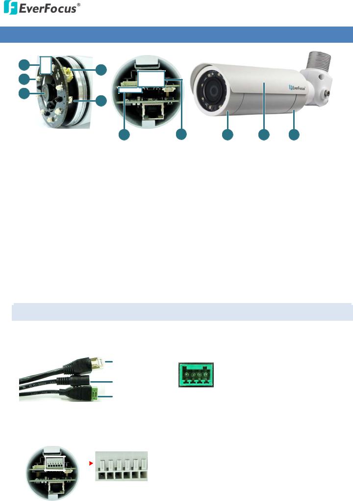
3. Physical Description
1 |
4 |
|
|
|
|
|
2 |
|
|
|
|
|
|
|
|
|
|
|
|
|
3 |
5 |
|
|
|
|
|
|
|
|
|
|
|
|
Front Module |
6 |
Rear Module |
7 |
8 |
9 |
10 |
No. |
Item Name |
|
Descriptions |
|
||
1 |
|
Light Sensor |
|
Detects lights. |
|
|
|
|
|
|
|
|
|
2 |
|
IR LEDs |
|
8 IR LEDs for infrared illumination in night vision applications. |
|
|
|
|
|
|
|
|
|
3 |
|
Lens |
|
Fixed lens. |
|
|
|
|
|
|
|
|
|
4 |
|
Video Test Output |
|
Connects to a handheld test monitor for adjusting camera view. |
|
|
|
|
|
|
|
|
|
5 |
|
Reset Button |
|
Resets all configurations to the factory default settings. |
|
|
|
|
|
|
|
|
|
6 |
|
Micro SD / SDHC Slot |
|
Insert a micro SD / SDHC card. See 4.3 Inserting a Micro SD Card. |
|
|
|
|
|
|
|
|
|
7 |
|
Spare Terminal Block |
|
For connecting to power or alarm I/O. See 3.1 Cables and Terminal Block. |
|
|
|
|
|
|
|
|
|
8 |
|
Front Cover |
|
Remove the cover for connecting to a handheld test monitor. |
|
|
|
|
|
|
|
|
|
9 |
|
Sunshield |
|
Protect the camera from the direct rays of the sun. |
|
|
|
|
|
|
|
|
|
10 |
Base Cover |
|
Remove the cover for inserting a micro SD card. |
|
||
|
|
|
|
|
|
|
|
|
|
|
|
|
|
3.1Cables and Terminal Block
The cables provide connections for Network, power and alarm input / output. The wires are illustrated and defined below.
LAN / PoE Cable |
Pin Assignment for Alarm I/O |
||
|
|
|
|
|
|
Alarm Out |
Pin 1: Alarm COM (-) |
|
|
Pin 2: Alarm Out (+) |
|
|
|
|
|
12 VDC / 24 VAC |
|
Alarm In |
Pin 3: Alarm In (+) |
|
4 3 2 1 |
Pin 4: Ground (-) |
|
Alarm Input / Output |
|
||
|
|
|
|
Spare Terminal Block on the Rear Module
To open the Rear Module, please refer to Step 1 to 3 in 4.3 Inserting a Micro SD Card.
|
|
|
Power |
Pin 1: 12 VDC+ / 24 VAC+ |
|
|
|
|
Pin 2: 12 VDC- / 24 VAC- |
||
|
|
|
|
||
|
|
|
Alarm Out |
Pin3: Alarm COM (-) |
|
|
|
|
|||
|
|
|
Pin4: Alarm Out (+) |
||
|
|
|
|||
|
|
|
|
||
|
|
|
|
|
|
6 5 4 3 2 1 |
Alarm In |
Pin5: Alarm In (+) |
|||
Pin6: Ground (-) |
|||||
|
|
|
|
||
|
|
|
3 |
|
|
EZN1160/1260/1360
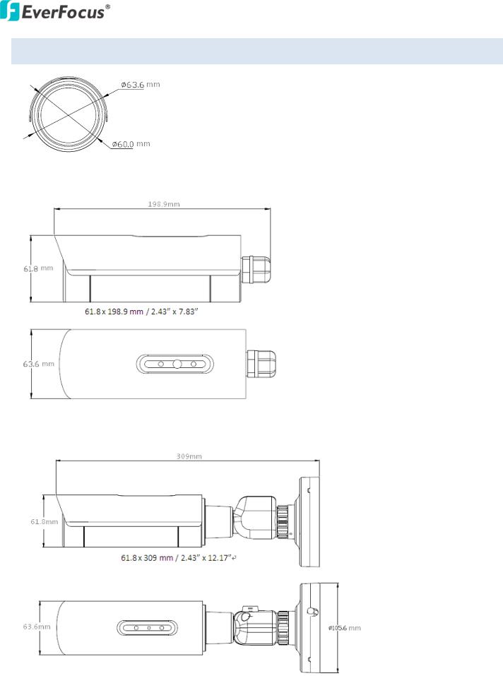
3.2Dimensions
Standard Model
Cable Management Model
4
EZN1160/1260/1360
4. Installation
4.1Packing List
Please check that there is no missing item in the package before installing. This series is supplied with two types: Standard and Cable Management.
Standard (with a stand) |
Cable Management (with a bracket) |
|
|
• Camera Stand Kit x 1 |
• Quick Mounting Ring x 1 |
|
(with 4 Long Screws and 4 Screw Anchors) |
•Short Screw x 4 (for connecting the camera base to the Quick Mounting Ring)
•Hexagon Key x 1 (for adjusting camera angle)
•Hexagon Wrench x 1 (for screwing the Set Screw)
•Cable Gland x 1* (with two conduits on the inner stopper)
•Test-Out Cable x 1
•4-Pin Terminal Block x 1
•RJ-45 connector x 1
•Power Pigtail Cable x 1
•Desiccant Bag x 1
•Software CD x 1
•Quick Installation Guide x 1
Note:
1.Equipment configurations and supplied accessories vary by country. Please consult your local EverFocus office or agents for more information. Please also keep the shipping carton for possible future use.
2.Contact the shipper if any items appear to have been damaged in the shipping process.
3.The item marked with a “*” varies among camera types.
5
EZN1160/1260/1360
4.2Basic Installation
Please follow the steps below to mount the camera to the wall.
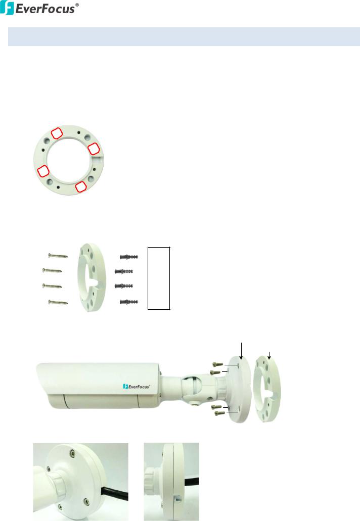
For the Cable Management Model:
1.Before screwing the camera to the wall, drill four holes on the wall according to the hole-positions on the supplied Quick-Mounting Ring. If you wish to run the wires into the wall, drill another hole in the middle of the circular area within the Quick-Mounting Ring.
2.Push the supplied four anchors into the four holes on the wall. Place the Quick-Mounting Ring against the anchoring surface so that the holes line up. Screw the Quick-Mounting Ring to the wall
using the supplied Long Screws.
Long Screws Quick-Mounting Ring Anchors
Wall
3.Screw the Camera Base to the Quick-Mounting Ring using the supplied four Short Screws.
Camera Base
Quick-Mounting Ring
Short Screws
Short Screws
You can wire the cables from the side of the camera or through the wall.
Wire the cables from |
Wire the cables |
the side of the camera |
through the wall |
6
EZN1160/1260/1360
4.Connect the network, power and other cables to the related devices. Please refer to 3.1 Cables and Terminal Block.
5.Optionally insert a micro SD / SDHC card into the card slot (see 4.3 Inserting a Micro SD Card).
Note: Please close the Base Cover immediately in case of reducing the absorption capacity of the desiccant bag inside the camera.
6.Access the camera live view. Please see 5. Accessing the User Interface. Or connect a handheld test monitor to the Video Test Output on the camera module for adjusting camera angles.
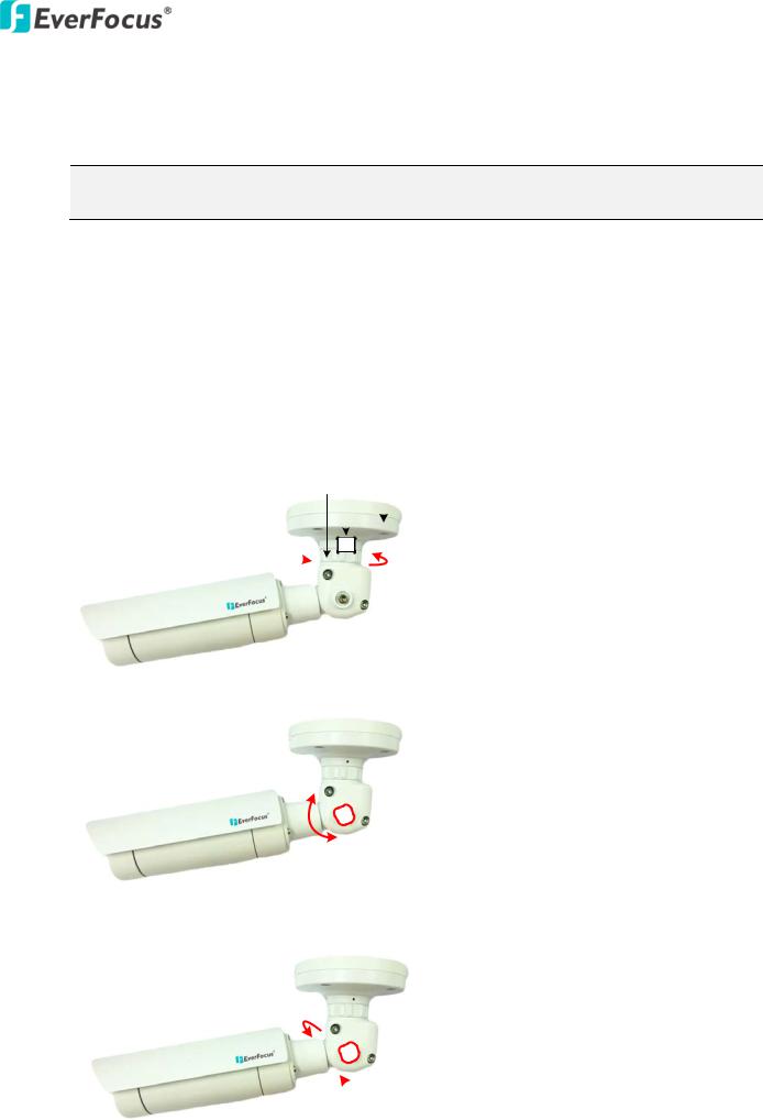
7.Adjust the camera angles.
Pan Adjustment: Unscrew the Set Screw using the supplied Hexagon Wrench. Twist the Camera Base forcefully until it unscrews from the E-Z Lock Ring. Rotate the camera by 360° to the desired position and screw the E-Z Lock Ring until it locks against the Camera Base. Screw back the Set Screw.
Set Screw
E-Z Lock Ring |
Camera Base |
|
|
|
|
|
|
|
|
|
|
360° 
Tilt Adjustment: Loosen the Screw using the provided Hexagon Key and adjust the tilt angle by 87°.
87°
Rotational Adjustment: Loosen the Screw using the providing Hexagon Key and rotate the camera by 360°.
360° 
7
EZN1160/1260/1360
For the Standard Model:
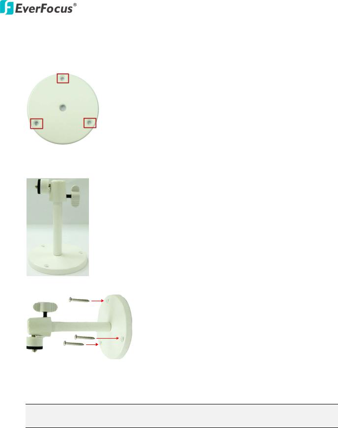
1.Before screwing the supplied Stand to the wall / ceiling, drill three holes on the wall / ceiling according to the hole-positions on the Base of the Stand.
2.Insert the supplied three Anchors into the holes on wall / ceiling.
3.Install the supplied Stand.
4. Screw the supplied Stand to the wall / ceiling using the supplied screws.
5.Optionally insert a micro SD / SDHC card into the card slot. Please refer to 4.3 Inserting a Micro SD Card.
Note: Please close the Base Cover immediately in case of reducing the absorption capacity of the desiccant bag inside the camera.
8
EZN1160/1260/1360
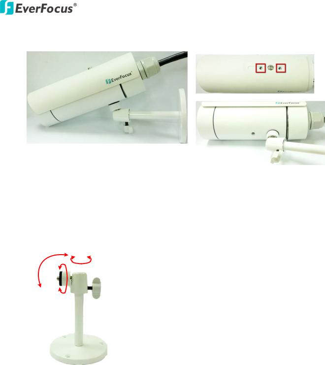
6.Screw the camera to the Stand using either one of the four holes (two on the top; two on the bottom) on the camera.
7.Connect the network, power and other cables of the camera to the related devices. Please refer to
3.1 Cables and Terminal Block.
8.Access the camera live view. Please see 5. Accessing the User Interface. Or connect a handheld test monitor to the Video Test Output on the camera module for adjusting camera angles (see image below).
360°
90°
360°
9
EZN1160/1260/1360
4.3Inserting a Micro SD Card
You can optionally insert a micro SD card into the card slot for recording videos.
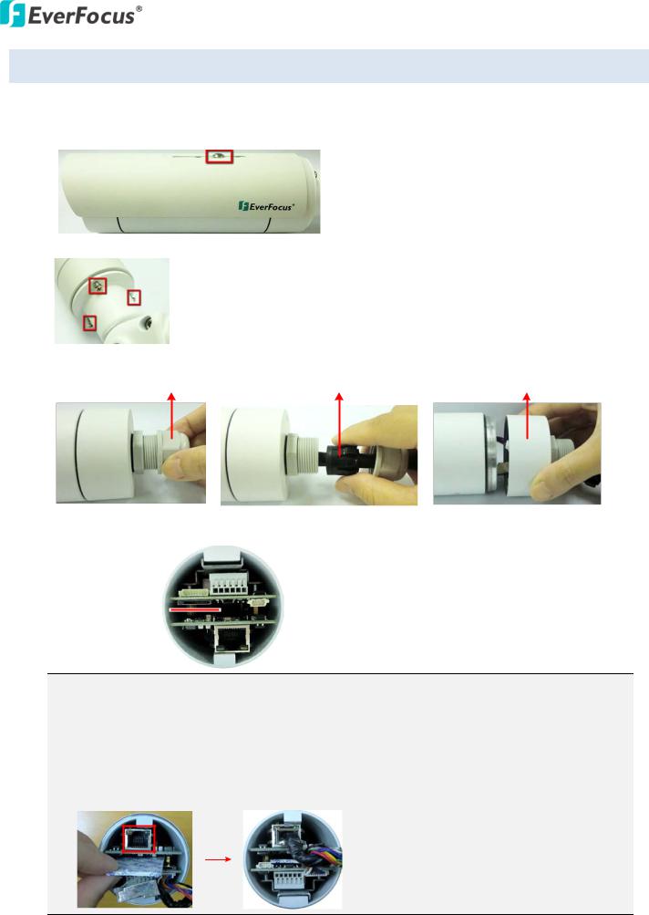
1.Loosen the screw to remove the Sunshield from the camera.
2.For Cable Management model, unscrew the three screws to remove the Bracket.
3.Unscrew the Screw Cap first, pull out the Stopper, and then rotate to remove the Base Cover.
Screw Cap |
Stopper |
Base Cover |
4.Insert a micro SD card into the card slot.
Micro SD Card Slot


Note:
1.Please close the Base Cover immediately in case of reducing the absorption capacity of the desiccant bag inside the camera.
2.To optionally replace a new desiccant bag, remove the used desiccant bag from the camera and then put the supplied Desiccant Bag in the middle layer. (Unplug the network cable if necessary)
5.Firmly close the Base Cover and Screw Cap, and then screw the Sunshield.
10
EZN1160/1260/1360
5. Accessing the User Interface
This section explains how to access the Web interface of the camera for configuration.
5.1Checking the Dynamic IP Address
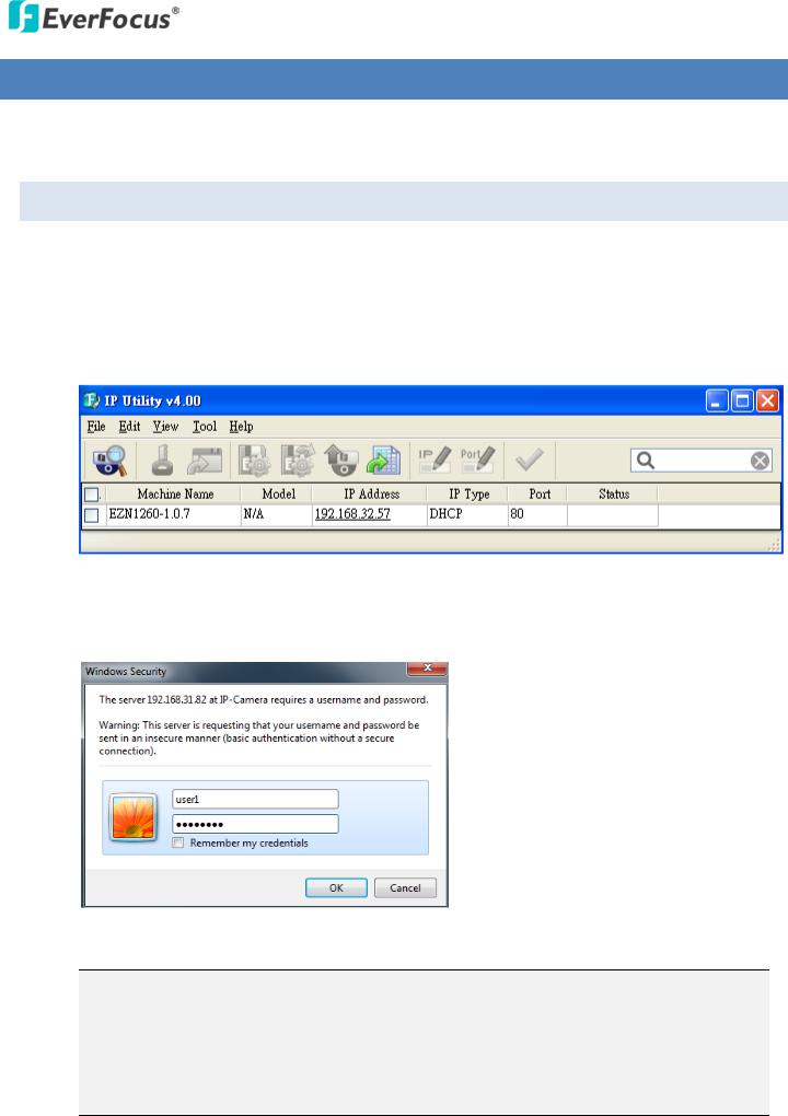
You can look up the IP address and access the Web interface of the camera using the IP Utility (IPU) software included in the software CD. Please connect the IP camera in the same LAN of your computer.
1.Install and then start the IPU program  . The following IPU window appears. The IPU will automatically search the IP devices connected in the LAN.
2.To access to the Live View window, double click the IP address of the desired device, the login window pops up. Type the user ID and password to log in. By default, the user ID is user1 and the password is 11111111.
3. Click OK, the Live View window appears.
Note:
1.You might be required to download ActiveX for viewing the camera feed. If asked, click Yes.
2.To enable Remote Live View, Firmware Upgrade and ActiveX Prompt on Internet Explorer, some settings have to be complete. Please refer to 5.2 Settings for Microsoft Internet Explorer in the User’s Manual.
11
EZN1160/1260/1360
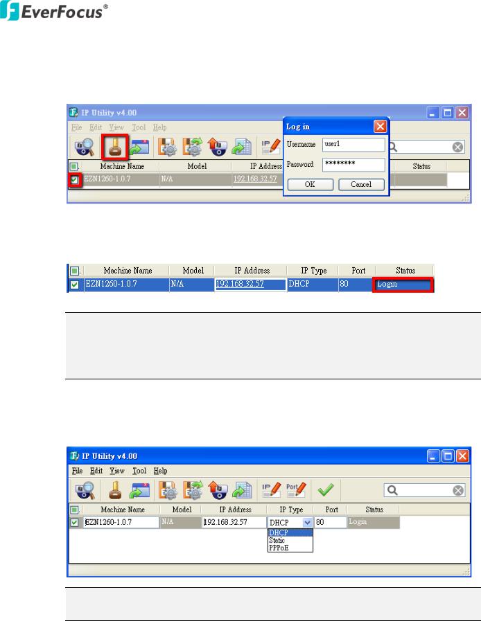
4.To optionally configure the Machine Name, IP Address, IP Type or Port Number using the IPU:
a.Log in the camera by checking the desired model and then click the Log in  icon. The Log in dialog box appears.
b.Type the Username and Password. Click the OK button, the status of the selected camera will displayed Login.
Note:
1.The default user ID is user1 and the default password is 11111111.
2.If you select more than one camera that has the same user ID / password, you will be able to log in several cameras at once.
c.Right click the column to configure the settings. Click the Apply Changes  button to apply and save the settings.
Note: Most networks uses DHCP to assign IP address, if you are unsure of your network settings, please consult your network administrators for configuration details.
12

EZN1160/1260/1360
5.2Settings for Microsoft Internet Explorer
To enable Remote Live View, Firmware Upgrade and ActiveX Prompt on Internet Explorer, some settings have to be complete. Please follow the steps below:
1.On the computer, click Start > Control Panel > System and Security > Action Center (click Change User Account Control Settings), the User Account Control Settings window appears. Adjust the slide bar to Never Notify and then click OK. Restart your computer if requested.
2.Open the Internet Explore, click Tools > Internet Options > Security Tab > Custom Level, the
Security Settings windows appears.
13

EZN1160/1260/1360
3.In the Download unsigned ActiveX controls field, select Prompt. In the Include local directory path when uploading files to a server field, select Enable. Click OK.
4.In the Internet Options window, click the Advanced tab and then disable Enable memory protection to help mitigate online attacks. Click OK.
14
EZN1160/1260/1360
5.3Connecting the Camera to the Network
There are three methods to connect the IP camera to the network: Router or LAN Connection, Direct High-Speed Connection and One-to-One Connection.
Router or LAN connection
This is the most common connection in which the IP camera is connected to a router and allows multiple users on and off site to see the IP camera on a LAN/WAN (Internet). The camera must be assigned an IP address that is compatible with its LAN. By setting up port forwarding on the router, you can remotely access the cameras from outside of the LAN via the Internet. To remotely access the Web interface of the IP camera, please refer to 7.1.1 Network (DDNS Settings). To set up port forwarding, please consult the manual of the router.
Straight-through LAN patch cable
Right: Pinout of a straight-through cable.
15
EZN1160/1260/1360
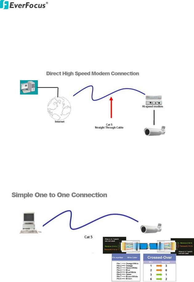
Direct High-Speed Connection
In a Direct High-Speed Connection, the camera connects directly to a modem without the need for a router. You need to set the static or dynamic WAN IP address assigned by your ISP (Internet Service Provider) in the camera’s configuration web pages. To access the camera, just type “http://xxx.xxx.xxx.xxx”, where xxx.xxx.xxx.xxx is the IP address given by your ISP. If you have a dynamic IP address, this connection may require that you use DDNS for a reliable connection. Please refer to
7.1.1 Network (DDNS Settings).
One-to-One Connection (Directly from PC to IP Camera)
You can connect directly without using a switch, router or modem. However, only the PC connected to the camera will be able to view the IP camera. You will also have to manually assign a compatible IP address to both the computer and the IP camera. Unless the PC has another network connection, the IP camera will be the only network device visible to the PC. See the diagram below:
Right: Pinout of a crossed-over cable.
16
Loading...