


 Loading...
EBN268 Outdoor Ball Network Camera
2-Megapixel, IR & WDR
User’s Manual
Copyright © EverFocus Electronics Corp,
Release Date: November, 2014

Copyright 1995-2014 EverFocus Electronics Corp.
All rights reserved. No part of the contents of this manual may be reproduced or transmitted in any form or by any means without written permission of the EverFocus Electronics Corporation.
EverFocus
12F-1, No.79, Sec. 1, Shin-Tai Wu Road, Hsi-Chih, New Taipei City, Taiwan
TEL: +886 2 2698 2334
FAX: +886 2 2698 3943 www.everfocus.com.tw
November, 2014
About this document
All the safety and operating instructions should be read and followed before the unit is operated. This manual should be retained for future reference. The information in this manual was current when published. The manufacturer reserves the right to revise and improve its products. All specifications are therefore subject to change without notice.
Regulatory Notices
FCC Notice "Declaration of Conformity Information"
This equipment has been tested and found to comply with the limits for a Class
A digital device, pursuant to part 15 of the FCC Rules. These limits are designed to provide reasonable protection against harmful interference in a residential installation. This equipment generates, uses and can radiate radio frequency energy and, if not installed and used in accordance with the instructions, may cause harmful interference to radio communications. However, there is no guarantee that interference will not occur in a particular installation. If this equipment does cause harmful interference to radio or television reception, which can be determined by turning the equipment off and on, the user is encouraged to try to correct the interference by one or more of the following measures:
-Reorient or relocate the receiving antenna.
-Increase the separation between the equipment and receiver.
-Connect the equipment into an outlet on a circuit different from that to which the receiver is connected.
-Consult the dealer or an experienced radio/TV technician for help.
Warning: Changes or modifications made to this equipment, not expressly approved by EverFocus or parties authorized by EverFocus could void the user's authority to operate the equipment.
This device complies with part 15 of the FCC Rules. Operation is subject to the following two conditions:
(1)This device may not cause harmful interference, and
(2)This device must accept any interference received, including interference that may cause undesired operation.
EverFocus Electronics Corp.
12F-1, No. 79, Sec. 1, Shin-Tai Wu Rd.,
Hsi-Chi, New Taipei City, Taiwan
EBN268 camera complies with CE and FCC.
i
Precautions
1. Do not install the camera near electric or magnetic fields.
Install the camera away from TV/radio transmitters, magnets, electric motors, transformers and audio speakers since the electromagnetic fields generated from these devices may distort the video image or otherwise interfere with camera operation.
2.Never disassemble the camera beyond the recommendations in this manual nor introduce materials other than those recommended herein.
Improper disassembly or introduction of corrosive materials may result in equipment failure or other damage.
3.Try to avoid facing the camera toward the sun.
In some circumstances, direct sunlight may cause permanent damage to the sensor and/or internal circuits, as well as creating unbalanced illumination beyond the capability of the camera to compensate.
4.Keep the power cord away from water and other liquids and never touch the power cord with wet hands.
Touching a wet power cord with your hands or touching the power cord with wet hands may result in electric shock.
5.Never install the camera in areas exposed to oil, gas or solvents.
Oil, gas or solvents may result in equipment failure, electric shock or, in extreme cases, fire.
6. Cleaning
For cameras with interchangeable lenses, do not touch the surface of the sensor directly with the hands. Use lens tissue or a cotton tipped applicator and ethanol to clean the sensor and the camera lens. Use a damp soft cloth to remove any dirt from the camera body. Please do not use complex solvents, corrosive or abrasive agents for cleaning of any part of the camera.
7.Do not operate the camera beyond the specified temperature, humidity or power source ratings.
Use the camera at temperatures within -10°C ~ 50°C / 14°F ~ 122°F, and humidity between 20% and 80%; this device is not rated as submersible. The input power source is 12 VDC / PoE. Be sure to connect the proper + / - polarity and voltage, as incorrect polarity or too high a voltage will likely cause the camera to fail, and such damage is not covered by the warranty. The use of properly fused or Class 3 power limited type supplies is highly recommended.
8.Mounting
Use care in selecting a solid mounting surface which will support the weight of the camera plus any wind, snow, ice or other loading, and securely attach the camera to the mounting surface using screws and anchors which will properly support the camera. If necessary (e.g. when mounting to drop ceilings) use a safety wire to provide additional support for the camera.
ii
|
|
|
CONTENTS |
|
1. |
Introduction .................................................................................................................................... |
1 |
||
2. |
Physical Description ...................................................................................................................... |
2 |
||
|
2.1 |
Dimensions....................................................................................................................................... |
3 |
|
3. |
Features |
................................................................................................................ |
3 |
|
4. |
Installation............................................................................................................ |
4 |
||
|
4.1 |
Packing .......................................................................................................................................List |
4 |
|
|
4.2 |
Basic ..............................................................................................................................Installation |
5 |
|
5. Accessing ........................................................................................................the User Interface |
7 |
|||
|
5.1 |
Checking ....................................................................................................the Dynamic IP Address |
7 |
|
|
5.2 |
Settings ..........................................................................................for Microsoft Internet Explorer |
9 |
|
|
5.3 |
Connecting ........................................................................................the Camera to the Network |
11 |
|
|
5.4 |
Live ..........................................................................................................................View Window |
13 |
|
6. |
Settings .......................................................................................................................................... |
|
16 |
|
|
6.1 |
System ..............................................................................................................................Settings |
17 |
|
|
6.1.1 ................................................................................................................................... |
Network |
17 |
|
|
6.1.2 .......................................................................................................................... |
Date / Time |
24 |
|
|
6.1.3 ................................................................................................................................. |
Storage |
25 |
|
|
6.1.4 .............................................................................................................. |
Display and Overlay |
26 |
|
|
6.1.5 ............................................................................................................ |
System Maintenance |
28 |
|
|
6.1.6 .............................................................................................................. |
System Information |
31 |
|
|
6.1.7 ...................................................................................................................................... |
User |
32 |
|
|
6.1.8 .................................................................................................................. |
Black /White List |
34 |
|
|
6.2 |
Camera .............................................................................................................................Settings |
35 |
|
|
6.2.1 ............................................................................................................................. |
Streaming |
35 |
|
|
6.2.2 ................................................................................................................................... |
Profile |
38 |
|
|
6.2.3 ................................................................................................................................. |
Camera |
40 |
|
|
6.2.4 ............................................................................................................................... |
Schedule |
43 |
|
|
6.2.5 .................................................................................................................................... |
Image |
44 |
|
|
6.3 |
Event .................................................................................................................................Settings |
46 |
|
|
6.3.1 ........................................................................................................................ |
Event Wizard |
46 |
|
|
6.3.2 .................................................................................................................................... |
Event |
47 |
|
|
6.3.3 .......................................................................................................................... |
Notification |
51 |
|
|
6.4 |
Link ...............................................................................................................to Smart Phone App |
54 |
|
iii
7. |
Upgrading Firmware Using IP Utility ........................................................................................ |
55 |
8. |
Specifications................................................................................................................................ |
57 |
9. |
Troubleshooting ........................................................................................................................... |
59 |
Appendix .............................................................................................................................................. |
62 |
|
|
Enabling the Multicast Function............................................................................................................... |
62 |
iv

EBN268
1. Introduction
The EBN268 is a 2-megapixel outdoor ball IP camera, providing 30 fps at 1920 x 1080 viewing resolution. The camera supports dual streams from H.264 and MJPEG video compression formats. Equipped with weather-resistance (IP66) housing plus 36 IR LEDs for enabling the night visibility of up to 30 meters, the camera meets a wide variety of needs for outdoor surveillance. Power over Ethernet (IEEE 802.3af) supplies power to the camera via the network for easy installation with only one cable, eliminating the need for power cables and reducing installation costs. EBN268 conforms to ONVIF / PSIA for compatibility with other network video devices – even from other manufacturers. You can also use EverFocus Mobile Applications to remotely view the live views of the cameras through your handheld devices; or use EverFocus CMS to remotely manage multiple IP devices connected on the network.
System Requirement
Before installing, please check that your computer meets these system requirements.
Operating System: Microsoft Windows XP / Vista (32-bit) / 7 (32-bit)
Microsoft Internet Explorer 7 or above
Note: For using the Internet Explorer, some settings are required. Please refer to 5.2 Settings for Microsoft Internet Explorer.
1
EBN268
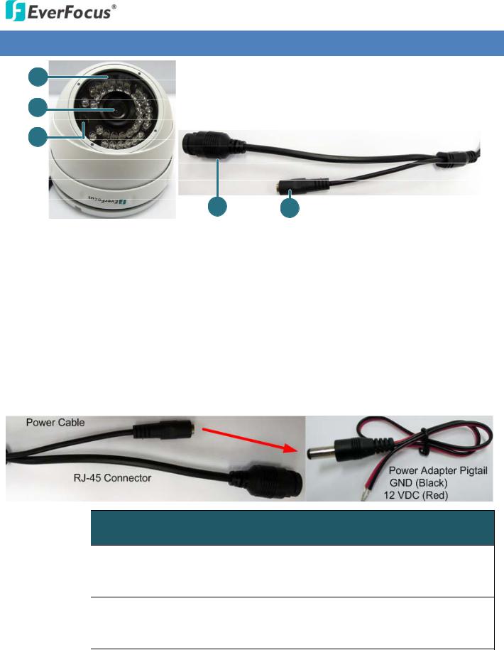
2. Physical Description
No. |
|
Item Name |
|
Descriptions |
1 |
|
IR LEDs |
|
36 IR LEDs for infrared illumination in night vision applications. |
2 |
|
Lens |
|
Fixed lens. |
3 |
|
Light Sensor |
|
Detects lights. |
4 |
|
RJ 45 Connector Cable |
|
Used to connect to a LAN/PoE cable. |
5 |
|
12 VDC Cable |
|
Used to connect to the power supply. |
Cable Connection
Cable Name |
Description |
|
|
Connects to the 12 VDC power source. You can optionally use the supplied Power |
|
Power Cable |
||
Adapter Pigtail or a power adapter. |
||
|
||
|
|
|
Power Adapter |
Connects one end to the Power Cable, and the other end to the 12 VDC power |
|
Pigtail |
source (black wire to ground end; red to positive end). |
|
|
|
2
EBN268
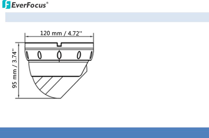
2.1 Dimensions
3.Features
•1/2.8” HD color CMOS image sensor delivers high resolution, and supports both H.264, MPEG-4 and M-JPEG in full frame rate
•Wide dynamic range
•Provides true day / night functionality with automatic IR filter operation
•Multi profiles settings for allows choice of image quality to fit the environment
•High performance noise filter improves image quality
•IP66 Weather Resistant
•Extended IR range of up to 30 m / 98.4 ft. with 36 LEDs
•Dual power capability PoE or 12 VDC for flexible installation
•Supports live monitoring of video from mobile devices via MobileFocus / MobileFocus Plus apps (iOS and Android)
•ONVIF / PSIA compliant
2
3

EBN268
4. Installation
4.1Packing List
Please check that there is no missing item in the package before installing.
• |
Camera x 1 |
• Hexagon Wrench x 1 (for adjusting camera angle) |
• |
Screw x 4 |
• Cable Gland and Screw Cap x 1 |
|
|
(with one conduit on the inner stopper) |
• |
Screw Anchor x 4 |
• Sticker x 1 |
• |
Set Screw x 3 |
• Quick Installation Guide x 1 |
• |
Software CD x 1 |
• Waterproof Ring x 1 |
• |
Power Adapter Pigtail x 1 |
|
Note:
1.Equipment configurations and supplied accessories vary by country. Please consult your local EverFocus office or agents for more information. Please also keep the shipping carton for possible future use.
2.Contact the shipper if any items appear to have been damaged in the shipping process.
4
EBN268
4.2Basic Installation
1.Before screwing the camera to the wall, stick the Sticker on the wall / ceiling to mark the position for installation. Drill four holes on the wall / ceiling according to the supplied Sticker and push the supplied four Anchors into the four holes on the wall / ceiling.
2.Twist the Outer Housing counterclockwise and then remove the Outer Housing from the camera base.
3.Place the camera base on the wall / ceiling and run the cable through the camera base first. Use the supplied four Screws to screw the camera base to the ceiling / wall.
4.Adjust the camera angle and twist back the Outer Housing simultaneously.
5.Optionally screw back the Set Screw by using the supplied Hexagon Wrench to prevent uninstallation.
5

EBN268
6.Connect the LAN / PoE cable to the camera. a. Remove the Screw Cap from the Cable Gland.
b.Insert a RJ 45 network cable (without the RJ 45 connector on the one end) through the Cable Gland and Screw Cap.
c.Place the Waterproof Ring into the LAN/PoE cable. Connect the RJ 45 cable to the RJ 45 Connector Cable. Tightly screw the Cable Gland and Screw Cap to the RJ 45 Connector Cable.
7.Optionally connect the camera to the 12 VDC power source using the supplied Power Adapter Pigtail or a power adapter.
6

EBN268
5.Accessing the User Interface
This section explains how to access the Web interface of the camera for configuration.
5.1Checking the Dynamic IP Address
You can look up the IP address and access the Web interface of the camera using the IP Utility (IPU) software included in the software CD or from the Website of EverFocus (click here to download). Please connect the IP camera in the same LAN of your computer.
1.Save IP Utility Setup AutoRun.exe  in your computer. Double click the .exe file and follow the on-screen instructions. Check Run IPUtility.exe and click the Finish button, the IP Utility will be launched to search the IP devices connected in the same LAN automatically.
2.To access to the Live View window, double click the IP address of the desired device, the login window pops up. Type the user ID and password to log in. By default, the user ID is user1 and the password is 11111111.
7

EBN268
3.Click OK, the Live View window appears.
Note:
1.You might be required to download ActiveX for viewing the camera feed. If asked, click Yes.
2.To enable Remote Live View, Firmware Upgrade and ActiveX Prompt on Internet Explorer, some settings have to be complete. Please refer to 5.2 Settings for Microsoft Internet Explorer in the User’s Manual.
4.To optionally configure the Machine Name, IP Address, IP Type or Port Number using the IPU:
a.Log in the camera by checking the desired model and then click the Log in  icon. The Log in dialog box appears.
b.Type the Username and Password. Click the OK button, the Login status displays.
Note:
1.The default user ID is user1 and the default password is 11111111.
2.If you select more than one camera that has the same user ID / password, you will be able to log in several cameras at once.
c.Right click the column to configure the settings. Click the Apply Changes  button to apply and save the settings.
Note:
1.Most networks uses DHCP to assign IP address, if you are unsure of your network settings, please consult your network administrators for configuration details.
2.If you want to set up PPPoE, please refer to 6.1.1 Network.
8

EBN268
5.2Settings for Microsoft Internet Explorer
To enable Remote Live View, Firmware Upgrade and ActiveX Prompt on Internet Explorer, some settings have to be complete. Please follow the steps below:
1.On the computer, click Start > Control Panel > System and Security > Action Center (click Change User Account Control Settings), the User Account Control Settings window appears. Adjust the slide bar to Never Notify and then click OK. Restart your computer if requested.
2.Open the Internet Explore, click Tools > Internet Options > Security Tab > Custom Level, the
Security Settings windows appears.
9

EBN268
3.In the Download unsigned ActiveX controls field, select Prompt. In the Include local directory path when uploading files to a server field, select Enable. Click OK.
4.In the Internet Options window, click the Advanced tab and then disable Enable memory protection to help mitigate online attacks. Click OK.
10

EBN268
5.3 Connecting the Camera to the Network
There are three methods to connect the IP camera to the network: Router or LAN Connection, Direct High Speed Connection and One to One Connection.
Router or LAN connection
This is the most common connection in which the IP camera is connected to a router and allows multiple users on and off site to see the IP camera on a LAN/WAN (Internet). The camera must be assigned an IP address that is compatible with its LAN. By setting up port forwarding on the router, you can remotely access the cameras from outside of the LAN via the Internet. To remotely access the Web interface of the IP camera, please refer to 6.1.1 DDNS. To set up port forwarding, please consult the manual of the router.
11

EBN268
Direct High Speed Connection
In a Direct High Speed Connection, the camera connects directly to a modem without the need for a router. You need to set the static or dynamic WAN IP address assigned by your ISP (Internet Service Provider) in the camera’s configuration web pages. To access the camera, just type “http://xxx.xxx.xxx.xxx”, where xxx.xxx.xxx.xxx is the IP address given by your ISP. If you have a dynamic IP address, this connection may require that you use DDNS for a reliable connection. Please refer to
6.1.1 DDNS.
One to One Connection (Directly from PC to IP Camera)
You can connect directly without using a switch, router or modem. However, only the PC connected to the camera will be able to view the IP camera. You will also have to manually assign a compatible IP address to both the computer and the IP camera. Unless the PC has another network connection, the IP camera will be the only network device visible to the PC. See the diagram below:
12

EBN268
5.4Live View Window
1.Live View 
Click the Live View button to display the Live View window. If you experience video feed lag time (if connected via Internet), you can reduce the resolution or limit the number of streams. See 6.2.1 Streaming.
2.Snapshot
Click the Snapshot button to take a snapshot.
Note: For Microsoft IE10 and above users, some settings have to be complete to enable this function (see B. Snapshot/Record error message in 9. Troubleshooting).
3.Record
Click the Record button to start / stop recording the current video stream. By default, this icon is only for one minute video recording and the recordings will be saved at C:\EverFocus\. To change the recording time, see File Size in 6.1.3 Storage. To change the location, see Record to Local in 6.1.3 Storage. To record long period recordings, please set up a recording schedule (Schedule Settings in 6.3.2 Event). To change the source video stream and recording format, see Recording and Snapshot Settings in 6.1.3 Storage.
Note: For Microsoft IE10 and above users, some settings have to be complete to enable this function (see B. Snapshot/Record error message in 9. Troubleshooting).
13

EBN268
4.Setting
Click the Setting button to enter the Settings page (see 6. Settings).
5.Wizard
Click the Wizard button to enter the Setup Wizard.
6. Hallway Display (9:16): Click the Rotate button |
to rotate the live image. This function |
allows users to monitor vertically oriented areas such as hallway, corridors and aisles.
Note: To achieve the best 9:16 display effect, it’s recommended to:
1.Install the camera sideways by rotating the camera to the left or right by 90°.
90°
2.Select a 16:9 View Size (e.g. 1920x1080 / 1024x768).
3.Use the Rotate button.
7.Video Stream
Select the Video Stream (Stream 1 and Stream 2) that will be displayed in the live view window on the bottom. (see 6.2.1 Streaming). The default setting is Stream 1 only. If extra streams required, EverFocus can customize the settings.
14
EBN268
8.View Size
Use this to select the appropriate view size and shape of the live view window on the bottom. A smaller size might increase transmission speed and video quality.
9.Language
Click the Language drop down list to select the desired language.
10.Digital Zoom
Click the zoom in / zoom out buttons or roll the mouse wheel to zoom in / out the camera live view. Click the Home button to go back to the home position.
Marquee Mode: Select this mode to drag around a portion of the live view window you want to zoom into with your mouse.
Normal Mode: Select this mode to set the zoom level in the magnified window. Clicking on the magnified image will re center the image around that point.
11.Status Display (info line that can be placed above video box or at bottom of page)
This shows the name of the camera that is currently active or being configured, current date/time and current frame rate. You can activate these info displays in the Overlay Text Settings (see 6.1.4 Display and Overlay).
12.Event signal icons (above video screen)
When a motion event is triggered, a signal icon will appear at the top right of the Live View window to alert the user.
Motion detection icons 


 : The colors of these motion event icons correspond to the
colors of the motion trigger areas you have configured in the Motion Settings (see 6.3.2 Event). Recording icon  : When the camera is recording to a PC based folder, this icon appears.
15
Loading...