


 Loading...
EverFocus EDN368ME, EDN368M, EDN288M, EZN368, EDN288ME User Manual
...Value IP Series Outdoor Network Camera
2-Megapixel 288 Series / 3-Megapixel 368 Series
User’s Manual
EBN288/368 |
EDN288/368M |
EZN288/368 |
EZN288/368M |
Copyright © EverFocus Electronics Corp.
Release Date: March, 2017

Copyright 1995-2017 EverFocus Electronics Corp.
Disclaimer
All the images including product pictures or screen shots in this document are for example only. The images may vary depending on the product and software version. Information contained in this document is subject to change without notice.
Copyright
All rights reserved. No part of the contents of this manual may be reproduced or transmitted in any form or by any means without written permission of the EverFocus Electronics Corporation.
EverFocus
12F-1, No.79, Sec. 1, Shin-Tai Wu Road,
Hsi-Chih, New Taipei City, Taiwan
TEL: +886 2 2698 2334
FAX: +886 2 2698 3943 www.everfocus.com.tw
March, 2017
About this document
All the safety and operating instructions should be read and followed before the unit is operated. This manual should be retained for future reference. The information in this manual was current when published. The manufacturer reserves the right to revise and improve its products. All specifications are therefore subject to change without notice.
Regulatory Notices
FCC Notice "Declaration of Conformity Information"
This equipment has been tested and found to comply with the limits for a Class
A digital device, pursuant to part 15 of the FCC Rules. These limits are designed to provide reasonable protection against harmful interference in a residential installation. This equipment generates, uses and can radiate radio frequency energy and, if not installed and used in accordance with the instructions, may cause harmful interference to radio communications. However, there is no guarantee that interference will not occur in a particular installation. If this equipment does cause harmful interference to radio or television reception, which can be determined by turning the equipment off and on, the user is encouraged to try to correct the interference by one or more of the following measures:
-Reorient or relocate the receiving antenna.
-Increase the separation between the equipment and receiver.
-Connect the equipment into an outlet on a circuit different from that to which the receiver is connected.
-Consult the dealer or an experienced radio/TV technician for help.
Warning: Changes or modifications made to this equipment, not expressly approved by EverFocus or parties authorized by EverFocus could void the user's authority to operate the equipment.
This device complies with part 15 of the FCC Rules. Operation is subject to the following two conditions:
(1)This device may not cause harmful interference, and
(2)This device must accept any interference received, including interference that may cause undesired operation.
EverFocus Electronics Corp.
12F-1, No. 79, Sec. 1, Shin-Tai Wu Rd.,
Hsi-Chi, New Taipei City, Taiwan
Value IP Series camera complies with CE and FCC.
i
Precautions
Do not install the camera near electric or magnetic fields.
Install the camera away from TV/radio transmitters, magnets, electric motors, transformers and audio speakers since the electromagnetic fields generated from these devices may distort the video image or otherwise interfere with camera operation.
Never disassemble the camera beyond the recommendations in this manual nor introduce materials
other than those recommended herein.
Improper disassembly or introduction of corrosive materials may result in equipment failure or other damage.
Try to avoid facing the camera toward the sun.
In some circumstances, direct sunlight may cause permanent damage to the sensor and/or internal circuits, as well as creating unbalanced illumination beyond the capability of the camera to compensate.
1.Keep the power cord away from water and other liquids and never touch the power cord with wet hands.
Touching a wet power cord with your hands or touching the power cord with wet hands may result in electric shock.
2.Never install the camera in areas exposed to oil, gas or solvents.
Oil, gas or solvents may result in equipment failure, electric shock or, in extreme cases, fire.
3. Cleaning
For cameras with interchangeable lenses, do not touch the surface of the sensor directly with the hands. Use lens tissue or a cotton tipped applicator and ethanol to clean the sensor and the camera lens. Use a damp soft cloth to remove any dirt from the camera body. Please do not use complex solvents, corrosive or abrasive agents for cleaning of any part of the camera.
4.Do not operate the camera beyond the specified temperature, humidity or power source ratings.
Use the camera at temperatures within -10°C ~ 50°C / 14°F ~ 122°F, and humidity between 0% and 90%; this device is not rated as submersible. The input power source is 12VDC / PoE. Be sure to connect the proper + / - polarity and voltage, as incorrect polarity or too high a voltage will likely cause the camera to fail, and such damage is not covered by the warranty. The use of properly fused or Class 3 power limited type supplies is highly recommended.
5.Mounting
Use care in selecting a solid mounting surface which will support the weight of the camera plus any wind, snow, ice or other loading, and securely attach the camera to the mounting surface using screws and anchors which will properly support the camera. If necessary (e.g. when mounting to drop ceilings) use a safety wire to provide additional support for the camera.
ii
|
|
|
|
CONTENTS |
|
1. |
Introduction................................................................................................................................ |
|
|
1 |
|
2. |
Physical Description .................................................................................................................. |
|
2 |
||
|
2.1. |
Dimensions ................................................................................................................................... |
|
4 |
|
3. |
Features ...................................................................................................................................... |
|
|
5 |
|
4. |
Installation.................................................................................................................................. |
|
|
6 |
|
|
4.1. |
Packing List.................................................................................................................................... |
|
6 |
|
|
4.2. |
Optional Accessory ....................................................................................................................... |
7 |
||
|
4.3. |
Cables............................................................................................................................................ |
|
|
8 |
|
4.4. |
Basic Installation ......................................................................................................................... |
|
10 |
|
|
|
4.4.1. |
Mounting and Wiring..................................................................................................... |
10 |
|
|
|
4.4.2. Inserting a Micro SD Card .............................................................................................. |
19 |
||
5. |
Accessing the Camera.............................................................................................................. |
|
22 |
||
|
5.1. |
Checking the Dynamic IP Address .............................................................................................. |
22 |
||
|
5.2. |
Settings for Microsoft Internet Explorer..................................................................................... |
24 |
||
|
5.3. |
Connecting the Camera to the Network..................................................................................... |
25 |
||
|
5.4. |
Live View Window |
...................................................................................................................... |
27 |
|
6. |
Quick Setup Panel .................................................................................................................... |
|
29 |
||
|
6.1 |
Streaming.................................................................................................................................... |
|
29 |
|
|
6.2 |
Camera........................................................................................................................................ |
|
|
30 |
|
6.3 |
Lens CTRL .................................................................................................................................... |
|
30 |
|
|
6.4 |
Account....................................................................................................................................... |
|
31 |
|
7. |
System ....................................................................................................................................... |
|
|
31 |
|
|
7.1. |
System Settings........................................................................................................................... |
|
32 |
|
|
|
7.1.1. |
Network ......................................................................................................................... |
|
32 |
|
|
|
7.1.1.1. |
IP Settings ..................................................................................................... |
32 |
|
|
|
7.1.1.2. |
Multicast Settings ......................................................................................... |
34 |
|
|
|
7.1.1.3. |
DDNS Settings............................................................................................... |
35 |
|
|
7.1.2. |
Date / Time .................................................................................................................... |
37 |
|
|
|
|
7.1.2.1. |
Date/Time Settings....................................................................................... |
37 |
|
|
|
7.1.2.2. |
NTP Settings.................................................................................................. |
37 |
|
|
7.1.3. |
Storage........................................................................................................................... |
|
38 |
|
|
7.1.4. |
Display and Overlay ....................................................................................................... |
39 |
|
|
|
7.1.5. |
System Maintenance ..................................................................................................... |
40 |
|
iii
|
|
|
7.1.5.1. |
Upgrade Firmware........................................................................................ |
40 |
|
|
|
7.1.5.2. |
Auto Reboot ................................................................................................. |
41 |
|
|
|
7.1.5.3. |
Restore.......................................................................................................... |
42 |
|
|
7.1.6. |
System Information ....................................................................................................... |
43 |
|
|
|
7.1.7. |
User................................................................................................................................ |
|
44 |
|
|
7.1.8. |
Serial Communication.................................................................................................... |
46 |
|
|
|
7.1.9. |
Local Settings ................................................................................................................. |
47 |
|
|
7.2. |
Camera Settings.......................................................................................................................... |
|
48 |
|
|
|
7.2.1. |
Streaming and Audio ..................................................................................................... |
48 |
|
|
|
|
7.2.1.1. |
Audio Settings............................................................................................... |
48 |
|
|
|
7.2.1.2. |
Stream Settings............................................................................................. |
49 |
|
|
|
7.2.1.3. |
Privacy Mask Settings................................................................................... |
50 |
|
|
7.2.2. |
Camera........................................................................................................................... |
|
51 |
|
|
7.2.3. |
Image ............................................................................................................................. |
|
54 |
|
7.3. |
Event Settings ............................................................................................................................. |
|
55 |
|
|
|
7.3.1. |
Event .............................................................................................................................. |
|
55 |
|
|
|
7.3.1.1. |
Motion Settings ............................................................................................ |
55 |
|
|
|
7.3.1.2. |
Tamper Detection Settings ........................................................................... |
57 |
|
|
|
7.3.1.3. |
Alarm Input................................................................................................... |
58 |
|
|
|
7.3.1.4. |
Alarm Output................................................................................................ |
60 |
|
|
|
7.3.1.5. |
Exception Settings ........................................................................................ |
61 |
|
|
7.3.2. |
Notification .................................................................................................................... |
62 |
|
|
|
|
7.3.2.1. |
Email Settings ............................................................................................... |
62 |
|
7.4. |
Search and Play........................................................................................................................... |
|
63 |
|
|
|
7.4.1. |
Playback ......................................................................................................................... |
|
63 |
|
|
7.4.2. |
File.................................................................................................................................. |
|
65 |
|
|
7.4.3. |
View Log......................................................................................................................... |
|
67 |
8. Upgrading Firmware Using IP Utility..................................................................................... |
68 |
||||
9. |
Specifications ........................................................................................................................... |
|
70 |
||
10. |
Troubleshooting ....................................................................................................................... |
|
71 |
||
Appendix |
............................................................................................................................................ |
|
|
72 |
|
|
A. |
Tested Card Brands ..................................................................................................................... |
72 |
||
|
B. |
Enabling the Multicast Function................................................................................................. |
73 |
||
|
C. |
RTSP URL Syntax ......................................................................................................................... |
|
75 |
|
|
D. |
Setting up Port Forwarding Function.......................................................................................... |
76 |
||
|
E. |
Setting up DDNS Function .......................................................................................................... |
78 |
||
iv

Value IP 2MP 288 Series / 3MP 368 Series
1. Introduction
The Value IP 2-megapixel 288 / 3-megapixel 368 series H.265 Outdoor IP camera provides 30fps at 1920 x 1080 / 2048 x 1536 viewing resolution. The series supports dual streams from H.265 or H.264 video compression formats. In same resolution, the H.265 provides higher compression efficiency and lower bitrate comparing with H.264 codec, allowing more efficient bandwidth and data storage usage. The True Wide Dynamic Range (WDR) function on the other hand enables the IP camera to provide clear images even under back light circumstances where intensity of illumination can vary excessively.
Featured with a motorized zoom lens, EDN288M / EZN288M / EDN368M / EZN368M can provide the desired field of view with superior video quality in precise focus. Equipped with a weather-proof (IP66) housing, the Value IP 288 / 368 series meets a wide variety of needs for outdoor surveillance. Except 12VDC power supply, the series also supports Power over Ethernet (IEEE 802.3af), which eliminates the need for power cables and thus reduce the installation costs.
The Value IP 288 / 368 series conforms to ONVIF for compatibility with other network video devices. You can also use EverFocus Mobile applications to remotely view the live views of the cameras through your iOS or android handheld devices; or use EverFocus CMS to remotely manage multiple IP devices connected on the network.
|
Model Name |
|
Lens |
|
Max. Video Resolution |
|
Storage |
|
|
IR / T-WDR |
|
IP66 / IK10 |
|
EBN288 |
|
3.6mm |
|
1920 x 1080 |
|
|
|
|
|
||
|
|
|
Fixed lens |
|
- |
|
|
|
|
Yes / - |
||
|
EBN368 |
|
|
2048 x 1536 |
|
|
|
|
||||
|
|
|
|
|
|
|
|
|||||
|
|
|
|
|
|
|
|
|
|
|
||
|
EDN288M |
|
2.8-12mm |
|
1920 x 1080 |
|
Micro SD / |
|
|
|
Yes / Yes |
|
|
|
|
Motorized lens |
|
|
|
|
|
|
|||
|
EDN368M |
|
|
2048 x 1536 |
|
|
Yes / Yes |
|
||||
|
|
|
|
|
|
|
||||||
|
|
|
|
|
|
|
SDHC / SDXC |
|
|
|||
|
EZN288 |
|
3.6mm |
|
1920 x 1080 |
|
|
|
||||
|
|
|
|
|
|
|
|
|||||
|
|
|
Fixed lens |
|
|
|
slot |
|
|
|
|
|
|
EZN368 |
|
|
2048 x 1536 |
|
|
|
|
Yes / - |
|||
|
|
|
|
|
|
|
||||||
|
|
|
|
|
|
|
(Max. 128G, |
|
|
|
||
|
EZN288M |
|
2.8-12mm |
|
1920 x 1080 |
|
|
|
|
|||
|
|
|
|
|
|
|
|
|||||
|
|
|
Motorized lens |
|
|
|
up to class 10) |
|
|
|
|
|
|
EZN368M |
|
|
2048 x 1536 |
|
|
|
|
|
|||
|
|
|
|
|
|
|
|
|||||
|
|
|
|
|
|
|
|
|
|
|
|
|
System Requirement
Before installing, please check that your computer meets the following system requirements.
Operating System: Microsoft Windows XP / Vista (32-bit) / 7 (32-bit)
Microsoft Internet Explorer 11 or later, Chrome (Windows version 44 and earlier), Firefox version 50 and earlier, EverFocus Browser
Note: For using the Internet Explorer, some settings are required. Please refer to 5.2 Settings for
Microsoft Internet Explorer.
1

Value IP 2MP 288 Series / 3MP 368 Series
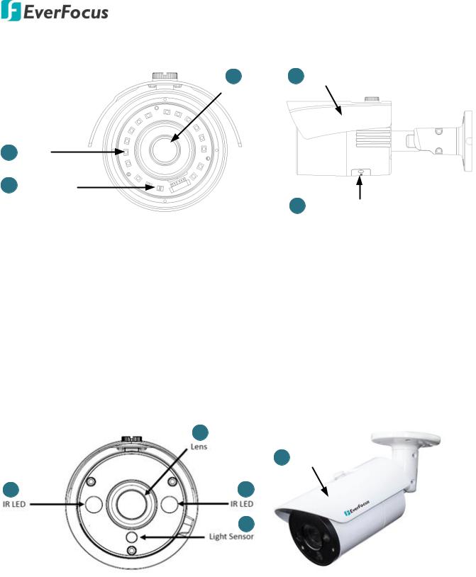
2. Physical Description
EBN288/368
No. |
|
|
|
Item Name |
|
Descriptions |
1 |
|
|
|
IR LEDs |
|
IR LEDs for infrared illumination in night |
|
|
|
|
vision applications. |
||
|
|
|
|
|
|
|
2 |
|
|
|
Lens |
|
Fixed lens. |
3 |
|
|
|
Light Sensor |
|
Detects lights. |
EDN288/368M |
|
|
|
|
1 |
|
No. |
Item Name |
Descriptions |
|
|
|
IR LEDs for infrared illumination in night |
|
|
3 |
1 |
IR LEDs |
|
2 |
|
|||
|
vision applications. |
|||
|
|
|
||
|
|
2 |
Lens |
Motorized lens. |
|
|
3 |
Light Sensor |
Detects lights. |
4 |
|
4 |
Micro SD / |
Insert a micro SD / SDHC card (see |
|
|
SDHC Slot |
Appendix for tested card brands). |
|
|
|
|
2
Value IP 2MP 288 Series / 3MP 368 Series
EZN288/368
|
|
|
|
2 |
4 |
Sunshield |
|
|
|
|
|
|
Lens |
|
|
1 |
IR LED |
|
|
|
|
||
3 |
Light Sensor |
|
|
|
|
||
|
|
|
|
|
|
5 |
Micro SD / SDHC Slot |
|
|
|
|
|
|
|
|
No. |
|
Item Name |
|
Descriptions |
|
|
|
1 |
|
|
IR LEDs |
|
IR LEDs for infrared illumination in night vision applications. |
||
2 |
|
|
Lens |
|
Fixed lens. |
|
|
3 |
|
|
Light Sensor |
|
Detects lights. |
|
|
4 |
|
|
Sunshield |
|
Protect the camera from the direct rays of the sun. |
||
5 |
|
|
Micro SD / SDHC Slot |
|
Insert a micro SD / SDHC card (see Appendix for tested card brands). |
||
EZN288/368M |
|
|
|
|
|||
|
|
|
|
2 |
|
|
|
|
|
|
|
4 |
Sunshield |
||
1 |
1 |
|
3 |
No. |
|
Item Name |
|
Descriptions |
1 |
|
IR LEDs |
|
IR LEDs for infrared illumination in night vision applications. |
2 |
|
Lens |
|
Motorized lens. |
3 |
|
Light Sensor |
|
Detects lights. |
4 |
|
Sunshield |
|
Protect the camera from the direct rays of the sun. |
|
|
|
3 |
|

Value IP 2MP 288 Series / 3MP 368 Series
2.1. Dimensions
EBN288/368
EDN288/368M
EZN288/368
EZN288/368M
4
Value IP 2MP 288 Series / 3MP 368 Series
3.Features
SONY Progressive Scan CMOS sensor
Astounding image quality from the 3.6mm lens (EBN288 / EBN 368 / EZN288 / EZN368)
Motorized 2.8-12mm lens to capture the desired field of view (EDN288M / EDN368M / EZN288M
/EZN368M)
True Wide Dynamic Range Function (120dB)
Provides True Day/Night functionality with automatic IR filter operation
Extended IR range up to 30m / 100ft. with IR LEDs (Depending on scene IR reflectivity)
Multi-streaming from H.265 / H.264
1080p full real time recording
Weather proof IP66-rated
The flexible angle viewing with its 3-Axis rotation design allows wall or ceiling mounting
Supports Motion Detection & Email Notification
Supports live monitoring of video from mobile devices via MobileFocus / MobileFocus plus Apps (iOS & Android)
Supports Power over Ethernet / 12VDC
Low light
Two-way audio*
Supports Alarm I/O*
Supports RS-485 (reserved)*
EverFocus Genie XMS CMS
ONVIF profile S compliant
Supports Micro SD card (EDN288M / EDN368M / EZN288 / EZN368 / EZN288M / EZN368M)
*Economic models do not include the feature
5

Value IP 2MP 288 Series / 3MP 368 Series
4. Installation
4.1. Packing List
Please check that there is no missing item in the package before installing.
No. |
Item Name |
|
EBN288/368 |
|
EDN288/368M |
|
EZN288/368 |
|
EZN288/368M |
1 |
Camera |
|
x 1 |
|
x 1 |
|
x 1 |
|
x 1 |
|
|
|
|
|
|
|
|
|
|
2 |
MAC Address Sticker |
|
x 2 |
|
x 2 |
|
x 2 |
|
x 2 |
|
|
|
|
|
|
|
|
|
|
|
Screw Anchor |
|
|
|
|
|
|
|
|
3 |
(in conjunction with |
|
x 4 |
|
x 3 |
|
x 3 |
|
x 4 |
|
Screw) |
|
|
|
|
|
|
|
|
|
|
|
|
|
|
|
|
|
|
4 |
Screw |
|
x 4 |
|
x 3 |
|
x 3 |
|
x 4 |
|
|
|
|
|
|
|
|
|
|
|
Hexagon Wrench |
|
|
|
|
|
|
|
|
5 |
(for adjusting the camera |
|
x 1 |
- |
|
x 1 |
|
x 1 |
|
|
position) |
|
|
|
|
|
|
|
|
|
|
|
|
|
|
|
|
|
|
|
Cable Gland Kit |
|
|
|
|
|
|
|
|
6 |
(connect to the LAN/PoE |
|
x 1 |
|
x 1 |
|
x 1 |
|
x 1 |
|
cable for waterproofing) |
|
|
|
|
|
|
|
|
|
|
|
|
|
|
|
|||
7 |
Set Screw |
|
x 3 |
- |
- |
- |
|||
|
|
|
|
|
|
|
|
|
|
8 |
Power Pigtail Cable |
|
x 1 |
|
x 1 |
|
x 1 |
|
x 1 |
|
|
|
|
|
|
|
|
|
|
|
Accessories Instruction |
|
|
|
|
|
|
|
|
9 |
(for installation of Set |
|
x 1 |
- |
- |
- |
|||
|
Screw) |
|
|
|
|
|
|
|
|
|
|
|
|
|
|
|
|
|
|
10 |
Software CD |
|
x 1 |
|
x 1 |
|
x 1 |
|
x 1 |
|
|
|
|
|
|
|
|
|
|
11 |
Quick Installation Guide |
|
x 1 |
|
x 1 |
|
x 1 |
|
x 1 |
|
|
|
|
|
|
|
|
|
|
12 |
Sticker |
|
x 1 |
|
x 1 |
|
x 1 |
|
x 1 |
(Mounting Template) |
|
|
|
|
|||||
|
|
|
|
|
|
|
|
|
|
|
|
|
|
|
|
|
|
|
|
Note:
1.Equipment configurations and supplied accessories vary by country. Please consult your local EverFocus office or agents for more information. Please also keep the shipping carton for possible future use.
2.Contact the shipper if any items appear to have been damaged in the shipping process.
6
Value IP 2MP 288 Series / 3MP 368 Series
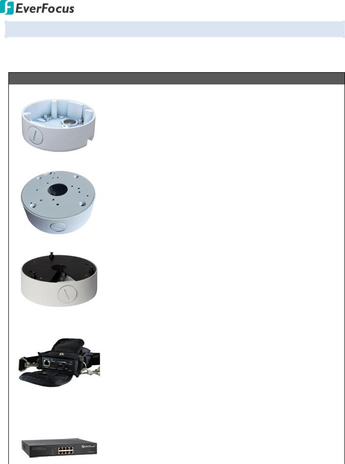
4.2. Optional Accessory
You can use the optional accessories to expand the capabilities and versatility of the camera. Please contact your dealer for more information.
Junction Box
|
PBOX-A32 |
Junction Box (For EBN288/368) |
|
|
|
|
|
Apple White |
|
|
119.2 x 38mm / 4.7" x 1.5" (D) x (H) |
|
|
High-strength Aluminum for better protection against damage. |
|
|
Spray painted surface to protect the bracket from corrosion and rust. |
|
PBOX-A32-1 |
|
|
|
Junction Box (For EZN288 / EZN368 / EZN288M / EZN368M) |
|
|
Apple White |
|
|
119.2 x 38mm / 4.7" x 1.5" (D) x (H) |
|
|
High-strength Aluminum for better protection against damage. |
|
|
Spray painted surface to protect the bracket from corrosion and rust. |
|
|
|
|
PBOX-A32-2 |
Junction Box (For EDN288M / EDN368M) |
|
|
|
|
|
Apple White |
|
|
119.2 x 38mm / 4.7" x 1.5" (D) x (H) |
|
|
High-strength Aluminum for better protection against damage. |
|
|
Spray painted surface to protect the bracket from corrosion and rust. |
IP Sidekick |
|
|
|
IP Sidekick - ESK1000 |
Using it for installation, you do not need to pre-configure the IP |
|
|
address or to use an additional monitor to check and adjust all the IP |
|
|
cameras. The product can assign an IP address to the camera, then you |
|
|
can connect and check the camera live view using EverFocus mobile |
|
|
App EF Sidekick. For details about IP Sidekick, please refer to the IP |
|
|
Sidekick – ESK1000 User’s Manual. |
|
|
|
PoE Switch |
|
|
EverFocus 5 / 8 / 16 / 24 |
5 Ports: ES0501-40 |
|
|
Ports PoE Switch |
8 Ports: ES0812-31 / ES0802-41 |
|
|
16 Ports: ES1625-31 / ES1645-51 |
|
|
24 Ports: ES2426-31 / ES2446-51 / ES2448-62 |
|
|
|
7

Value IP 2MP 288 Series / 3MP 368 Series
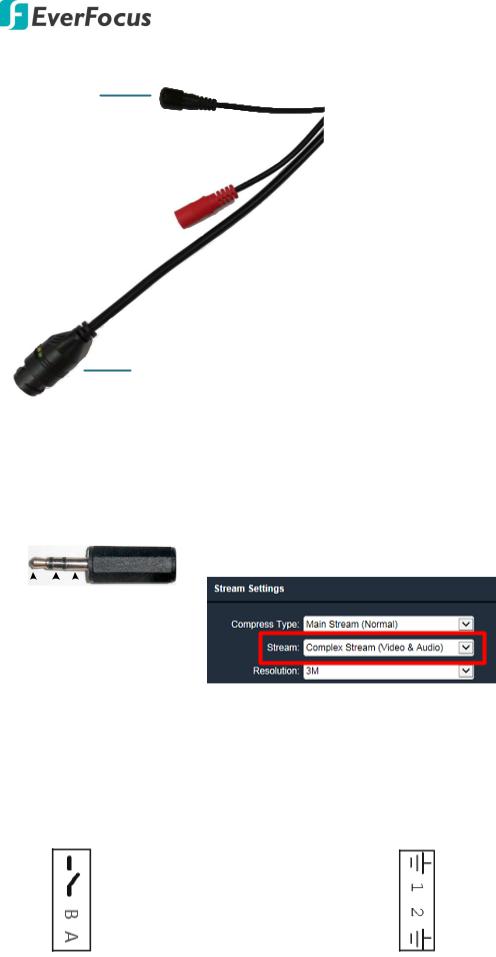
4.3. Cables
The Cables provide connections for Network, BNC output, power, audio input / output, RS-485 (reserved) and alarm inputs / output. A Reset Button is also provided. Note that the audio-in / out cable features a line 3.5mm jack (TRS). Be sure to prepare microphones / speakers with TRS connector (see TRS Connector image below). Also, microphones / speakers with a (built-in) amplifier and external power supply are required.
Reset Button 
Alarm Output /
RS-485 (Red)
Audio Output (TRS Line-out)
(White)
Alarm Input (Black) 
Video Output 
12VDC Input 
Audio Input (TRS Line-in)
(Red)
LAN / PoE Cable 
Cable |
|
EBN288/368 |
|
EDN288/368M |
|
|
EZN288/368 |
|
|
EZN288/368M |
Alarm In x 2 |
|
Yes (with a |
|
Yes (with a |
|
Yes (with a |
|
Yes (with a |
||
|
terminal block) |
|
terminal block) |
|
terminal block) |
|
terminal block) |
|||
|
|
|
|
|
||||||
|
|
|
|
|
|
|
|
|
|
|
Alarm Out / |
|
Yes (with a |
|
Yes (with a |
|
Yes (with a |
|
Yes (with a |
||
RS-485 |
|
|
|
|
||||||
|
terminal block) |
|
terminal block) |
|
terminal block) |
|
terminal block) |
|||
(reserved) |
|
|
|
|
||||||
|
|
|
|
|
|
|
|
|
|
|
|
|
|
|
|
|
|
|
|
||
Audio In |
|
Yes (Red) |
|
Yes (Red) |
|
Yes (Red) |
|
Yes (Red) |
||
|
|
|
|
|
|
|
|
|
||
Audio Out |
|
Yes (White) |
|
Yes (White) |
|
Yes (White) |
|
Yes (White) |
||
|
|
|
|
|
|
|
|
|
||
BNC |
|
Yes |
|
Yes |
|
Yes |
|
Yes |
||
|
|
|
|
|
|
|
|
|
||
RJ45 |
|
Yes |
|
Yes |
|
Yes |
|
Yes |
||
|
|
|
|
|
|
|
|
|
||
12VDC |
|
Yes |
|
Yes |
|
Yes |
|
Yes |
||
|
|
|
|
|
|
|
|
|
|
|
Reset Button |
|
Yes (with a |
- |
|
- |
|
|
Yes (with a |
||
|
dust-proof cap) |
|
|
|
dust-proof cap) |
|||||
|
|
|
|
|
|
|
|
|
||
|
|
|
|
|
|
|
|
|
|
|
8
Value IP 2MP 288 Series / 3MP 368 Series
For Economic models, the cables provide connections for Network, power and Reset Button.
Reset Button
12VDC Input 
LAN / PoE Cable
Economic Models Cables
|
Cable |
|
EBN288/368 |
EDN288/368M |
|
|
RJ45 |
|
Yes |
Yes |
|
|
|
|
|
|
|
|
12VDC |
|
Yes |
Yes |
|
|
|
|
|
|
|
|
Reset |
|
Yes (with a |
|
|
|
|
dust-proof |
- |
|
|
|
Button |
|
|
||
|
|
cap) |
|
|
|
|
|
|
|
|
|
|
|
|
|
|
|
|
Cable |
EZN288/368 |
|
|
EZN288/368M |
|
RJ45 |
Yes |
|
Yes |
|
|
|
|
|
|
|
|
12VDC |
Yes |
|
Yes |
|
|
|
|
|
|
|
|
Reset |
- |
|
|
Yes (with a |
|
Button |
|
|
dust-proof cap) |
|
|
|
|
|
||
|
|
|
|
|
|
Audio Function |
|
||||||
|
|
|
|
|
|
TRS Connector |
To activate the Audio function, the Complex Stream must be selected. |
|
|
|
|
|
|
|
See Stream in 7.2.1.2 Streaming Settings. |
|
|
|
|
|
|
Ground (Sleeve) |
|
|
|
|
|
|
|
|
|
|
|
|
|
|
|
|
|
|
|
|
|
|
Right Channel (Ring) |
|
|
|
|
|
|
|
|
||
|
|
|
Left Channel (Tip) |
|
|||
|
|
|
|
||||
Pin Assignment |
|
|
|
|
|
|||
|
|
|
|
|
|
|
|
|
|
|
Alarm Output / RS-485 (reserved) |
|
Alarm Input |
||||
|
|
|
|
|
|
|
|
|
|
|
|
Alarm Output |
COM (-) |
|
|
Alarm In 1 |
GND (-) |
|
|
|
|
|
|
|
||
|
|
NO (+) |
Alarm In (+) |
|||||
|
|
|
|
|
|
|
||
|
|
|
|
|
|
|
|
|
|
|
|
RS-485 |
B (+) |
|
|
Alarm In 2 |
Alarm In (+) |
|
|
|
(reserved) |
|
|
|
|
|
|
|
|
A (-) |
GND (-) |
||||
|
|
|
|
|
|
|||
|
|
|
|
|
|
|
|
|
9
Value IP 2MP 288 Series / 3MP 368 Series
Reset Button
1.Reboot the camera:
When the camera is powered up, press the Reset Button will reboot the camera.
2.Restore the camera:
Keep the Reset Button pressed, at the same time unplug the camera power then plug it back again will return camera settings to the factory default values.
4.4.Basic Installation
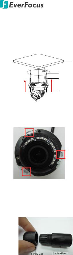
4.4.1.Mounting and Wiring EBN288/368
1.Before screwing the camera to the wall, stick the Sticker on the wall / ceiling to mark the position for installation. Drill four holes on the wall / ceiling according to the supplied Sticker and push the supplied four Screw Anchors into the four holes on the wall / ceiling. Drill another hole in the middle of the Sticker if you wish to run the wires into the wall / ceiling.
2.Twist the Outer Housing counterclockwise and then remove the Outer Housing from the camera base.
3. Place the camera base on the wall / ceiling and run the cable through the camera base first.
10

Value IP 2MP 288 Series / 3MP 368 Series
4.Tread the cables:
a. From the side cut of the camera base
b. Through the wall / ceiling: run the cables through the hole on the wall / ceiling.
 Wall or
Ceiling
5. Use the supplied four Screws to screw the camera base to the ceiling / wall.
6.Adjust the camera angle and twist back the Outer Housing simultaneously.
7.Optionally screw back the Set Screw by using the supplied Hexagon Wrench to prevent uninstallation.
11

Value IP 2MP 288 Series / 3MP 368 Series
8.Connect the LAN / PoE cable to the camera.
a. Remove the Screw Cap from the Cable Gland.
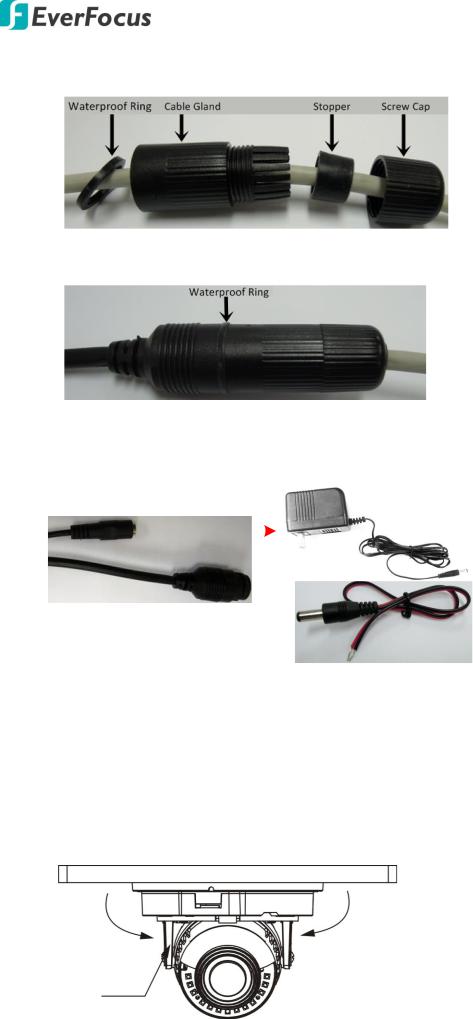
b.Insert a RJ-45 network cable (without the RJ-45 connector on the one end) through the Cable Gland and Screw Cap.
c.Place the Waterproof Ring into the LAN / PoE cable. Connect the RJ-45 cable to the RJ-45 Connector Cable. Tightly screw the Cable Gland and Screw Cap to the RJ-45 Connector Cable.
9.Optionally connect the camera to the 12VDC power source using the supplied Power Adapter Pigtail or a power adapter.
Power Cable |
|
Power Adapter |
|
|
|
|
|
|
or
RJ-45 Connector
Power Adapter Pigtail
12
Value IP 2MP 288 Series / 3MP 368 Series
EDN288/368M
1.Before screwing the camera to the wall, stick the Sticker on the wall / ceiling to mark the position for installation. According to the supplied Sticker, drill three screw-depth holes on the wall / ceiling, and then drill a through-wall hole for wiring the camera cables. Push the supplied three Screw Anchors into the four holes on the wall / ceiling.
Wall or Ceiling
Sticker
Anchors
Screws
2.Unscrew the camera cover and screw the camera base to the ceiling / wall by using the supplied
Screws.
3.Optionally insert the micro SDHC / SDXC card. Please refer to 4.4.2 Inserting a micro SD Card.
4.Connect the LAN / PoE cable to the camera.
a. Remove the Screw Cap from the Cable Gland.
13
Value IP 2MP 288 Series / 3MP 368 Series
b.Insert a RJ-45 network cable (without the RJ-45 connector on the one end) through the Cable Gland and Screw Cap.
c.Place the Waterproof Ring into the LAN / PoE cable. Connect the RJ-45 cable to the RJ-45 Connector Cable. Tightly screw the Cable Gland and Screw Cap to the RJ-45 Connector Cable.
5.Optionally connect the camera to the 12VDC power source using the supplied Power Adapter Pigtail or a power adapter.
Power Cable |
|
Power Adapter |
|
|
|
|
|
|
or
RJ-45 Connector
Power Adapter Pigtail
6.Access the camera live view. See 5. Accessing the Camera. Or using a video Test-Out cable to connect a monitor to the camera for setting image aim and focus.
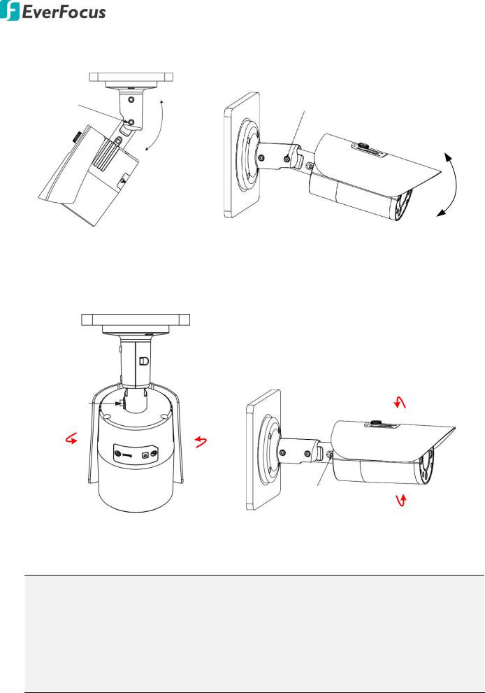
7.To adjust camera angles.
Pan Adjustment: Simply turn left / right of the 3-Axis bracket by 75° to the desired position.
75° |
75° |
3-Axis Bracket
14
Value IP 2MP 288 Series / 3MP 368 Series
Rotational Adjustment: Loosen the rotate screw and rotate the camera left / right to the desired position, then tighten the rotate screw. Due to the internal connector design, it is recommended not to rotate the camera more than 30°.
30° 30°
Rotation screw
Tilt Adjustment: Loosen the two tilt screws and adjust the angle by 75° to the desired position, then tighten the tilt screw.
Tilt screw
75°
8. Secure the cover back to the camera.
EZN288/368 & EZN288/368M
1.Before screwing the camera to the wall, stick the Sticker on the wall / ceiling to mark the position for installation. Drill three (EZN288/368) or four (EZN288/368M) holes on the wall / ceiling according to the supplied Sticker and push the supplied Anchors into the three holes on the wall / ceiling. Drill another hole in the middle of the Sticker if you wish to run the wires into the wall / ceiling.
EZN288/368 |
EZN288/368M |
15
Value IP 2MP 288 Series / 3MP 368 Series
2. You can wire the cables from the side of the camera or through the wall.
Wire the cables from the side of the camera |
Wire the cables through the wall |
3.Place the camera’s base against the anchoring surface so that the holes line up. Screw the camera to the wall / ceiling using the supplied Screws.
4.Optionally insert a micro SD / SDHC card into the card slot. Please refer to 4.4.2 Inserting a micro SD Card.
5.Connect the LAN / PoE cable to the camera.
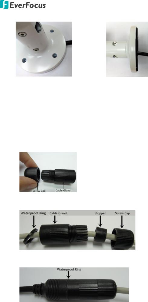
a. Remove the Screw Cap from the Cable Gland.
b.Insert a RJ-45 network cable (without the RJ-45 connector on the one end) through the Cable Gland and Screw Cap.
c.Place the Waterproof Ring into the LAN / PoE cable. Connect the RJ-45 cable to the RJ-45 Connector Cable. Tightly screw the Cable Gland and Screw Cap to the RJ-45 Connector Cable.
16
Value IP 2MP 288 Series / 3MP 368 Series
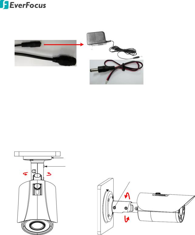
6.Optionally connect the camera to the 12VDC power source using the supplied Power Adapter Pigtail or a power adapter.
Power Cable |
Power Adapter |
|
or
RJ-45 Connector
Power Adapter Pigtail
7.Access the camera live view. See 5. Accessing the Camera. Or connect a handheld test monitor to the CVBS wire on the Cable Assembly for adjusting viewing angles.
8.To adjust the camera angles:
Pan Adjustment: Loosen the Set Screw using the supplied Hexagon Wrench. Rotate the camera by 360° to the desired position and screw the Set Screw until it locks against the Camera Base.
Camera
Base
Set Screw
360° |
Camera Base |
|
|
Set Screw |
|
|
||
|
|
|
|
|
|
360°
EZN288/368 |
EZN288/368M |
17
Value IP 2MP 288 Series / 3MP 368 Series
Tilt Adjustment: Loosen the Set Screw using the provided Hexagon Wrench and adjust the angle by 90°.
Set Screw
90°
Set Screw
90°
EZN288/368 EZN288/368M
Rotational Adjustment: Loosen the Screw using the provided Hexagon Wrench and rotate the camera by 360°.
Set Screw
Set Screw
EZN288/368 |
EZN288/368M |
Note:
1.Before start operating the IP camera, please make sure the camera date and time are correct. To configure the camera date/time, go to System > Date/Time setting page on Web UI.
2.By default, the system will automatically adjust the IR LED strength according to the scene, so please avoid IR reflection when installing the camera to prevent out-of-focus at night.
3.Under Auto focus mode, if the camera does not focus after switching the Day/Night mode, it is recommended to switch the focus mode to Manual and adjust focus manually.
18

Value IP 2MP 288 Series / 3MP 368 Series
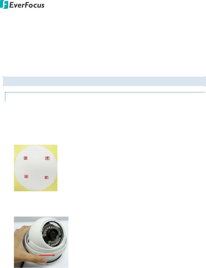
4.4.2.Inserting a Micro SD Card
You can optionally insert a micro SD card to the card slot on the camera module for recording videos. Before inserting a micro SD card, make sure you turn off the camera first.
EDN288/368M
1.Unscrew and then remove the camera cover.
2.Insert a micro SD card into the card slot.
EZN288/368
4.Open the cover on the bottom of the camera by loosening the screws.
5.Insert a micro SD card into the card slot.
19

Value IP 2MP 288 Series / 3MP 368 Series
EZN288/368M
1.Loosen the two set screws on the bracket.
Set Screw
2.Loosen the three screws on the rear housing. Rotate and then remove the rear housing.
3.Loosen the four screws on the IPC board.
4.Insert a micro SD card into the card slot.
20

Value IP 2MP 288 Series / 3MP 368 Series
5.Put the water-proof ring on the groove that near the edge of the housing. Place the desiccant bag beside the IPC board.
 Desiccant bag
 Water-proof ring
6.Screw back the IPC board, secure the rear housing back to the front housing and tighten the set screws on the bracket.
Note: Please make sure you wear the antistatic gloves or antistatic wrist strap when installing the
Micro SD card to protect the device from damage.
21
Loading...